EP0474841B1 - Artificial limb component - Google Patents
Artificial limb component Download PDFInfo
- Publication number
- EP0474841B1 EP0474841B1 EP91907321A EP91907321A EP0474841B1 EP 0474841 B1 EP0474841 B1 EP 0474841B1 EP 91907321 A EP91907321 A EP 91907321A EP 91907321 A EP91907321 A EP 91907321A EP 0474841 B1 EP0474841 B1 EP 0474841B1
- Authority
- EP
- European Patent Office
- Prior art keywords
- turntable
- inner member
- outer member
- collet
- ring
- Prior art date
- Legal status (The legal status is an assumption and is not a legal conclusion. Google has not performed a legal analysis and makes no representation as to the accuracy of the status listed.)
- Expired - Lifetime
Links
- 210000003414 extremity Anatomy 0.000 claims abstract description 20
- 210000003141 lower extremity Anatomy 0.000 claims abstract description 6
- 239000000463 material Substances 0.000 claims description 4
- 229920001169 thermoplastic Polymers 0.000 claims description 2
- 239000004416 thermosoftening plastic Substances 0.000 claims description 2
- 210000001364 upper extremity Anatomy 0.000 abstract 1
- 210000003127 knee Anatomy 0.000 description 15
- 239000004033 plastic Substances 0.000 description 3
- 229920003023 plastic Polymers 0.000 description 3
- 229930182556 Polyacetal Natural products 0.000 description 2
- 239000004743 Polypropylene Substances 0.000 description 2
- 238000004519 manufacturing process Methods 0.000 description 2
- 229920006324 polyoxymethylene Polymers 0.000 description 2
- -1 polypropylene Polymers 0.000 description 2
- 229920001155 polypropylene Polymers 0.000 description 2
- 239000004677 Nylon Substances 0.000 description 1
- 230000009286 beneficial effect Effects 0.000 description 1
- 230000006835 compression Effects 0.000 description 1
- 238000007906 compression Methods 0.000 description 1
- 230000000694 effects Effects 0.000 description 1
- 239000002783 friction material Substances 0.000 description 1
- 229920001778 nylon Polymers 0.000 description 1
Images

Classifications
-
- A—HUMAN NECESSITIES
- A61—MEDICAL OR VETERINARY SCIENCE; HYGIENE
- A61F—FILTERS IMPLANTABLE INTO BLOOD VESSELS; PROSTHESES; DEVICES PROVIDING PATENCY TO, OR PREVENTING COLLAPSING OF, TUBULAR STRUCTURES OF THE BODY, e.g. STENTS; ORTHOPAEDIC, NURSING OR CONTRACEPTIVE DEVICES; FOMENTATION; TREATMENT OR PROTECTION OF EYES OR EARS; BANDAGES, DRESSINGS OR ABSORBENT PADS; FIRST-AID KITS
- A61F2/00—Filters implantable into blood vessels; Prostheses, i.e. artificial substitutes or replacements for parts of the body; Appliances for connecting them with the body; Devices providing patency to, or preventing collapsing of, tubular structures of the body, e.g. stents
- A61F2/50—Prostheses not implantable in the body
- A61F2/76—Means for assembling, fitting or testing prostheses, e.g. for measuring or balancing, e.g. alignment means
-
- A—HUMAN NECESSITIES
- A61—MEDICAL OR VETERINARY SCIENCE; HYGIENE
- A61F—FILTERS IMPLANTABLE INTO BLOOD VESSELS; PROSTHESES; DEVICES PROVIDING PATENCY TO, OR PREVENTING COLLAPSING OF, TUBULAR STRUCTURES OF THE BODY, e.g. STENTS; ORTHOPAEDIC, NURSING OR CONTRACEPTIVE DEVICES; FOMENTATION; TREATMENT OR PROTECTION OF EYES OR EARS; BANDAGES, DRESSINGS OR ABSORBENT PADS; FIRST-AID KITS
- A61F2/00—Filters implantable into blood vessels; Prostheses, i.e. artificial substitutes or replacements for parts of the body; Appliances for connecting them with the body; Devices providing patency to, or preventing collapsing of, tubular structures of the body, e.g. stents
- A61F2/50—Prostheses not implantable in the body
- A61F2/60—Artificial legs or feet or parts thereof
- A61F2/64—Knee joints
-
- A—HUMAN NECESSITIES
- A61—MEDICAL OR VETERINARY SCIENCE; HYGIENE
- A61F—FILTERS IMPLANTABLE INTO BLOOD VESSELS; PROSTHESES; DEVICES PROVIDING PATENCY TO, OR PREVENTING COLLAPSING OF, TUBULAR STRUCTURES OF THE BODY, e.g. STENTS; ORTHOPAEDIC, NURSING OR CONTRACEPTIVE DEVICES; FOMENTATION; TREATMENT OR PROTECTION OF EYES OR EARS; BANDAGES, DRESSINGS OR ABSORBENT PADS; FIRST-AID KITS
- A61F2/00—Filters implantable into blood vessels; Prostheses, i.e. artificial substitutes or replacements for parts of the body; Appliances for connecting them with the body; Devices providing patency to, or preventing collapsing of, tubular structures of the body, e.g. stents
- A61F2/50—Prostheses not implantable in the body
- A61F2/78—Means for protecting prostheses or for attaching them to the body, e.g. bandages, harnesses, straps, or stockings for the limb stump
- A61F2/80—Sockets, e.g. of suction type
-
- A—HUMAN NECESSITIES
- A61—MEDICAL OR VETERINARY SCIENCE; HYGIENE
- A61F—FILTERS IMPLANTABLE INTO BLOOD VESSELS; PROSTHESES; DEVICES PROVIDING PATENCY TO, OR PREVENTING COLLAPSING OF, TUBULAR STRUCTURES OF THE BODY, e.g. STENTS; ORTHOPAEDIC, NURSING OR CONTRACEPTIVE DEVICES; FOMENTATION; TREATMENT OR PROTECTION OF EYES OR EARS; BANDAGES, DRESSINGS OR ABSORBENT PADS; FIRST-AID KITS
- A61F2/00—Filters implantable into blood vessels; Prostheses, i.e. artificial substitutes or replacements for parts of the body; Appliances for connecting them with the body; Devices providing patency to, or preventing collapsing of, tubular structures of the body, e.g. stents
- A61F2/02—Prostheses implantable into the body
- A61F2/30—Joints
- A61F2002/30001—Additional features of subject-matter classified in A61F2/28, A61F2/30 and subgroups thereof
- A61F2002/30316—The prosthesis having different structural features at different locations within the same prosthesis; Connections between prosthetic parts; Special structural features of bone or joint prostheses not otherwise provided for
- A61F2002/30329—Connections or couplings between prosthetic parts, e.g. between modular parts; Connecting elements
- A61F2002/30433—Connections or couplings between prosthetic parts, e.g. between modular parts; Connecting elements using additional screws, bolts, dowels, rivets or washers e.g. connecting screws
-
- A—HUMAN NECESSITIES
- A61—MEDICAL OR VETERINARY SCIENCE; HYGIENE
- A61F—FILTERS IMPLANTABLE INTO BLOOD VESSELS; PROSTHESES; DEVICES PROVIDING PATENCY TO, OR PREVENTING COLLAPSING OF, TUBULAR STRUCTURES OF THE BODY, e.g. STENTS; ORTHOPAEDIC, NURSING OR CONTRACEPTIVE DEVICES; FOMENTATION; TREATMENT OR PROTECTION OF EYES OR EARS; BANDAGES, DRESSINGS OR ABSORBENT PADS; FIRST-AID KITS
- A61F2220/00—Fixations or connections for prostheses classified in groups A61F2/00 - A61F2/26 or A61F2/82 or A61F9/00 or A61F11/00 or subgroups thereof
- A61F2220/0025—Connections or couplings between prosthetic parts, e.g. between modular parts; Connecting elements
- A61F2220/0041—Connections or couplings between prosthetic parts, e.g. between modular parts; Connecting elements using additional screws, bolts, dowels or rivets, e.g. connecting screws
Definitions
- This invention relates to a turntable for an artificial limb, which is arranged to allow rotation of an upper component of the limb relative to a lower component of the limb about a longitudinal axis, as specified in the preamble of claim 1.
- a turntable is disclosed, for example, in EP-A-0226278.
- the turntable has a lock for preventing rotation during normal use of the limb but which is generally manually releasable so that the amputee may, when required, rotate the lower part of the limb including the knee about the longitudinal axis.
- the present invention provides a turntable for connecting together an upper component and a lower component of an artificial limb such that the two components are rotatable with respect to each other about a longitudinal turntable rotation axis, characterised in that the turntable comprises: an inner member having a head portion and a neck portion for connecting the head portion to one of the said limb components, and an outer member for connection to or associated with the other of the said limb components and having a radially inwardly extending portion adjacent the neck portion of the inner member whereby the head portion is rotatably trapped by the outer member, and in that the turntable further comprises annular adjustable bearing means encircling the axis, the bearing means being associated with the inner member and bearing against a generally radially extending surface of the outer member so as to urge a bearing surface of the inner member head portion against a bearing surface of the outer member.
- the bearing means By appropriate adjustment of the bearing means, thereby altering the thrust applied to the outer member, play between the bearing surfaces can be largely eliminated. Play, which may be caused
- the bearing means comprises a collet of adjustable size arranged to act against the outer member and an opposing surface associated with the inner member. Either the collet itself or one of the surfaces it engages, or both, may be inclined when viewed in a transverse cross-section so that if the collet is adjusted in diameter the outer member is forced away from the opposing surface to urge the inter-engaging bearing surfaces of the inner and outer members together.
- the collet is circular and has an inwardly tapering cross-section.
- the collet when in use, is secured so as to rotate with the inner member, and has an inwardly directed conical surface which bears against a corresponding outwardly directed conical surface on the outer member. Since the inner member is rotatable with respect to the outer member and, therefore, the collet is also rotatable with respect to the outer member, it is possible, by tightening the collet beyond the point at which play is eliminated, to produce a required degree of resistance to rotation in use of the turntable due to friction between the inter-engaging conical surfaces.
- the collet is preferably manufactured from a flexible thermoplastics material such as a polyacetal, which is sufficiently flexible to allow adjustment of diameter, and is in the form of a ring with a single generally radial gap bridged by a tangentially oriented adjusting screw.
- a flexible thermoplastics material such as a polyacetal
- the head and neck portions of the inner member are integrally formed with an axial threaded stud for securing the inner member to the top plate of a knee mechanism.
- the collet may be located on the outer circumferential edge of a washer fitted on the stud and positioned to be trapped between the inner member neck portion and the knee mechanism top plate when the inner member is secured to a top plate.
- the outer member preferably has a concave spherical socket-mounting surface remote from the inner member for receiving the corresponding convex spherical end surface of a stump socket which may be secured to the outer member by an axial bolt passing through a plate inside the socket, and through a hole in the end of socket to engage a central threaded bore in the outer member.
- the invention also includes a turntable comprising two members which are rotatable with respect to each other about a longitudinal axis of the limb and which may be locked together to prevent such rotation by means of a locking device, wherein the locking device is mounted in one of the members and has a locking pawl which is inwardly tapered in a transverse cross-section and is generally radially movable into and out of a correspondingly tapered recess in the other member.
- the locking device By arranging for the locking device to be spring loaded, so that the tapered pawl is urged into the tapered recess, rotational play between the members in the locked position is largely eliminated.
- the angle of the taper is sufficiently large that the possibility of the pawl becoming jammed in the recess due to friction between the inter engaging surfaces of the pawl recess is largely avoided.
- the invention includes a lower limb prosthesis incorporating a turntable as described above.
- a turntable 10 in accordance with the invention serves to connect a plastics stump socket 12 (preferably formed by polypropylene) and a knee mechanism 14 of a lower limb prosthesis for an above-knee amputee.
- a plastics stump socket 12 preferably formed by polypropylene
- a knee mechanism 14 of a lower limb prosthesis for an above-knee amputee.
- the turntable has three main parts, which are an inner member 16 with a depending stud 16S for attaching the turntable to the top plate 14P of the knee mechanism 14 by means of a nut 18 threaded on the stud 16S and a washer 20 beneath the plate, an outer member 22 surrounding the inner member 16 and allowing the latter to rotate inside it about a longitudinally axis 24 of the limb, and an adjustable collet 26 of inwardly tapering cross-section located between an outwardly directed lower conical surface 22S of the outer member 22 and the top plate 14P of the knee mechanism.
- the inner member has a head portion 16E, and a neck portion 16N which is of smaller diameter than the end portion 16E and which connects the latter to the stud 16S.
- the end portion 16E defines an annular groove around the neck portion 16N and below a radially extending bearing surface 16ES of the end portion 16E.
- the outer member 22 surrounds the neck and end portions of the inner member 16, and is formed in two parts as follows.
- An upper part 22U has a concave part-spherical seating surface 22SS for receiving a corresponding convex part-spherical lower surface 12S of the stump socket 12.
- the socket 12 is attached to the upper part 22U of the outer member 22 by means of a bolt 28 which passes through a plate 30 internal to the socket, and through a hole 12H at the end of the socket into a threaded bore 22B in the upper part 22U.
- a layer of friction material 22F is bonded to the concave surface 22SS to prevent movement of the socket 12 on the surface when the bolt 28 has been tightened.
- the spherical shape of the concave surface 22SS and of the corresponding convex surface 12S of the socket 12, in conjunction with the relatively large hole in the polypropylene material of the socket allows a degree of alignment adjustment to be formed by moving the turntable relative to the socket.
- the upper part 22U of the outer member 22 overlies the end portion 16E of the inner member and is bolted by means of bolts 22BO to a lower part 22L of the outer member having a portion 22I which extends inwardly to encircle the neck portion 16N of the inner member 16.
- This inwardly extending portion 22I has an upper radially extending bearing surface 22IS facing the bearing surface 16ES on the inner member end portion 16E. Since the inwardly extending portion 22I of the outer member lies within the groove defined by the end and neck portions 16E and 16N of the inner member 16, the inner member 16 is trapped within the outer member 22 and is rotatable relative to the outer member about the longitudinal axis 24.
- the inner member 16 has a nylon or similar plastics bearing lining 30 of top-hat cross-section which bears against the outer member 22, to reduce friction.
- the inner member 16 although trapped within and rotatable within the outer member 22, is free to move axially by a small amount.
- This axial play between the members 16 and 22 is taken up by interposing the collet 26 between the lower conical surface 22S of the outer member 22 and the top plate 14P of the knee mechanism 14.
- the collet 26 is of inwardly tapering cross-section, having a lower surface 26L which engages the knee mechanism top plate 14P, and an inwardly and upwardly directed concave conical surface 26U which engages the corresponding convex conical surface 22S of the outer member 22.
- the collet 26 comprises a ring of the ring so formed being bridged by a screw 32 having a head 32H seated in one end portion of the ring and a threaded portion 32T threaded in a bore in the other end portion of the ring.
- the diameter of the collet 26 is thus adjustable, and it will be appreciated that the conical cross section of the collet, as shown in the detail of Figure 4, will result in the outer member 22 of the turntable being urged upwardly against the end portion 16E of the inner member 16 when the screw 32 is tightened. Consequently, it is possible to eliminate the vertical play between the inner and outer members 16 and 22.
- the collet 26 is located on the outer edge of a washer 34 encircling the stud 16S of the inner member 16. This washer is trapped between the inner member 16 and the top plate 14P of the knee mechanism, and is prevented from rotating with respect of the knee mechanism when the nut 18 is tightened.
- the washer 34 In its outer edge, the washer 34 has a groove of semi-circular cross-section for receiving a rubber O-ring 36. A similar groove 26G is cut in the inner edge of the collet 26 for receiving the outer part of the O-ring 36. It follows, that the collet 26 is flexibly mounted on the washer 34, and can therefore be adjusted in diameter.
- the collet 26 is preferably made of a plastics material such as polyacetal so as to be both light and sufficiently flexible to be adjusted in diameter.
- Three cut-outs 26C increase the flexibility of the collet 26 and have the secondary function of increasing the resistance to rotation of the collet 26 about the washer 34 since the O-ring 36 expands into these cut-outs.
- a collet 26 with a conical surface also substantially prevents rocking of the outer member 22 with respect to the inner member 16, and the O-ring 36 resists side play.
- the turntable is locked by a locking device.
- the locking device is released so as to allow the knee mechanism 14 and the lower part of the limb to be rotated with respect to the stump socket 12.
- the outer member 22 of the turntable is split into an upper part 22U and a lower part 22L.
- the locking device is visible, as shown in Figure 5.
- the locking device comprises a locking pawl 38P mounted on one end of a locking shaft 38S which extends transversely in the upper part 22U of the outer member offset to one side of the longitudinally axis 24.
- a locking button 38B accessible to the user.
- a compression spring 40 is mounted on the shaft 38S between the locking button 38B and a shoulder 22US on the outer member upper part 22U, thereby biasing the locking pawl 38P inwardly away from the outer periphery of the outer member 22.
- the spring 40 is shown compressed, with locking pawl 38P in its outer position, allowing rotation of the turntable.
- the locking pawl 38P projects downwardly from the outer member upper part 22U to engage in a notch (not shown) in the inner member 16 of the turntable when the pawl and notch are in registry with each other and the button 38B is released.
- the pawl 38P has side surfaces 38PS at least one of which is angled so that the pawl is inwardly tapered in the direction of the locking button 38B.
- the notch in the inner member 16 is similarly tapered. This has the effect of positively preventing rotational play between the inner and outer members 16 and 22 when the lock is engaged.
- the angle of inclination of the side surfaces of the pawl 38P is arranged such that the possibility of the pawl 38P being forced out of the notch in the inner member 16 due to a rotational force being applied to the turntable is avoided. Conversely, the angle of inclination is sufficiently great to avoid the pawl 38P becoming jammed in the notch.
Landscapes
- Health & Medical Sciences (AREA)
- Transplantation (AREA)
- Biomedical Technology (AREA)
- Cardiology (AREA)
- Oral & Maxillofacial Surgery (AREA)
- Engineering & Computer Science (AREA)
- Heart & Thoracic Surgery (AREA)
- Vascular Medicine (AREA)
- Life Sciences & Earth Sciences (AREA)
- Animal Behavior & Ethology (AREA)
- General Health & Medical Sciences (AREA)
- Public Health (AREA)
- Veterinary Medicine (AREA)
- Orthopedic Medicine & Surgery (AREA)
- Prostheses (AREA)
Abstract
Description
- This invention relates to a turntable for an artificial limb, which is arranged to allow rotation of an upper component of the limb relative to a lower component of the limb about a longitudinal axis, as specified in the preamble of claim 1. Such a turntable is disclosed, for example, in EP-A-0226278.
- It is well known to provide a lower limb prosthesis for an above-knee amputee with a turntable located proximally of the knee. One of the primary functions of the turntable is to allow the amputee to sit cross-legged. Conventionally, the turntable has a lock for preventing rotation during normal use of the limb but which is generally manually releasable so that the amputee may, when required, rotate the lower part of the limb including the knee about the longitudinal axis.
- In the past, it has proved difficult to design a turntable which is effective in operation, reliable, and yet relatively inexpensive to manufacture.
- The present invention provides a turntable for connecting together an upper component and a lower component of an artificial limb such that the two components are rotatable with respect to each other about a longitudinal turntable rotation axis, characterised in that the turntable comprises: an inner member having a head portion and a neck portion for connecting the head portion to one of the said limb components, and an outer member for connection to or associated with the other of the said limb components and having a radially inwardly extending portion adjacent the neck portion of the inner member whereby the head portion is rotatably trapped by the outer member, and in that the turntable further comprises annular adjustable bearing means encircling the axis, the bearing means being associated with the inner member and bearing against a generally radially extending surface of the outer member so as to urge a bearing surface of the inner member head portion against a bearing surface of the outer member. By appropriate adjustment of the bearing means, thereby altering the thrust applied to the outer member, play between the bearing surfaces can be largely eliminated. Play, which may be caused by manufacturing tolerances or by wear, can seriously affect the effectiveness of the limb.
- In the preferred embodiment of the invention the bearing means comprises a collet of adjustable size arranged to act against the outer member and an opposing surface associated with the inner member. Either the collet itself or one of the surfaces it engages, or both, may be inclined when viewed in a transverse cross-section so that if the collet is adjusted in diameter the outer member is forced away from the opposing surface to urge the inter-engaging bearing surfaces of the inner and outer members together. In a particularly advantageous arrangement the collet is circular and has an inwardly tapering cross-section.
- Preferably, the collet, when in use, is secured so as to rotate with the inner member, and has an inwardly directed conical surface which bears against a corresponding outwardly directed conical surface on the outer member. Since the inner member is rotatable with respect to the outer member and, therefore, the collet is also rotatable with respect to the outer member, it is possible, by tightening the collet beyond the point at which play is eliminated, to produce a required degree of resistance to rotation in use of the turntable due to friction between the inter-engaging conical surfaces.
- The collet is preferably manufactured from a flexible thermoplastics material such as a polyacetal, which is sufficiently flexible to allow adjustment of diameter, and is in the form of a ring with a single generally radial gap bridged by a tangentially oriented adjusting screw.
- In the preferred embodiment of the invention, the head and neck portions of the inner member are integrally formed with an axial threaded stud for securing the inner member to the top plate of a knee mechanism. The collet may be located on the outer circumferential edge of a washer fitted on the stud and positioned to be trapped between the inner member neck portion and the knee mechanism top plate when the inner member is secured to a top plate. By providing an inwardly directed groove on the inner edge of the collet and a similar outwardly directed groove on the outer edge of the washer it is possible to locate the collet on the washer by means of an O-ring located in the grooves. It has been found that the presence of a rubber O-ring of a suitable size between the collet and the washer not only serves to locate the collet on the washer but prevents it rotating with respect to the washer when the outer member rotates. The resistance to rotation offered by the O-ring is aided in the preferred embodiment by cut-outs in the inner edge of the collet, into which the O-ring is free to expand. The resilience of the O-ring assists in releasing the collet bearing surfaces should stiction occur during adjustment, and it has the advantage of keeping the collet located on the washer during assembly of the turntable to the knee mechanism. Side play of the collet with respect to the washer is also avoided.
- The outer member preferably has a concave spherical socket-mounting surface remote from the inner member for receiving the corresponding convex spherical end surface of a stump socket which may be secured to the outer member by an axial bolt passing through a plate inside the socket, and through a hole in the end of socket to engage a central threaded bore in the outer member.
- The invention also includes a turntable comprising two members which are rotatable with respect to each other about a longitudinal axis of the limb and which may be locked together to prevent such rotation by means of a locking device, wherein the locking device is mounted in one of the members and has a locking pawl which is inwardly tapered in a transverse cross-section and is generally radially movable into and out of a correspondingly tapered recess in the other member. By arranging for the locking device to be spring loaded, so that the tapered pawl is urged into the tapered recess, rotational play between the members in the locked position is largely eliminated. The angle of the taper is sufficiently large that the possibility of the pawl becoming jammed in the recess due to friction between the inter engaging surfaces of the pawl recess is largely avoided.
- The invention includes a lower limb prosthesis incorporating a turntable as described above.
- The invention will now be described by way of example with reference to the drawings in which:-
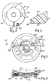
- Figure 1 is a vertical cross-section of part of a lower limb prosthesis for an above-knee amputee and including a turntable in accordance with the invention, the prosthesis being viewed from one side;
- Figure 2 is a plan view of the turntable of Figure 1, the sectioning line for Figure 1 being shown by the line I - I;
- Figure 3 is a top plan view of an adjustable collet and washer assembly forming part of the turntable of Figures 1 and 2;
- Figure 4 is a detail cross-section through the collet;
- Figure 5 is an underside view of an upper part of the turntable showing a locking device; and
- Figure 6 is a transverse cross-section of the upper part shown in Figure 5 along with the line VI - VI in Figure 5.
- Referring to Figures 1 and 2, a
turntable 10 in accordance with the invention serves to connect a plastics stump socket 12 (preferably formed by polypropylene) and aknee mechanism 14 of a lower limb prosthesis for an above-knee amputee. The turntable has three main parts, which are aninner member 16 with a dependingstud 16S for attaching the turntable to thetop plate 14P of theknee mechanism 14 by means of anut 18 threaded on thestud 16S and awasher 20 beneath the plate, anouter member 22 surrounding theinner member 16 and allowing the latter to rotate inside it about alongitudinally axis 24 of the limb, and anadjustable collet 26 of inwardly tapering cross-section located between an outwardly directed lowerconical surface 22S of theouter member 22 and thetop plate 14P of the knee mechanism. - The inner member has a
head portion 16E, and aneck portion 16N which is of smaller diameter than theend portion 16E and which connects the latter to thestud 16S. By virtue of its larger diameter, theend portion 16E defines an annular groove around theneck portion 16N and below a radially extending bearing surface 16ES of theend portion 16E. Theouter member 22 surrounds the neck and end portions of theinner member 16, and is formed in two parts as follows. Anupper part 22U has a concave part-spherical seating surface 22SS for receiving a corresponding convex part-sphericallower surface 12S of thestump socket 12. Thesocket 12 is attached to theupper part 22U of theouter member 22 by means of abolt 28 which passes through aplate 30 internal to the socket, and through ahole 12H at the end of the socket into a threadedbore 22B in theupper part 22U. A layer offriction material 22F is bonded to the concave surface 22SS to prevent movement of thesocket 12 on the surface when thebolt 28 has been tightened. The spherical shape of the concave surface 22SS and of thecorresponding convex surface 12S of thesocket 12, in conjunction with the relatively large hole in the polypropylene material of the socket allows a degree of alignment adjustment to be formed by moving the turntable relative to the socket. Theupper part 22U of theouter member 22 overlies theend portion 16E of the inner member and is bolted by means of bolts 22BO to alower part 22L of the outer member having a portion 22I which extends inwardly to encircle theneck portion 16N of theinner member 16. This inwardly extending portion 22I has an upper radially extending bearing surface 22IS facing the bearing surface 16ES on the innermember end portion 16E. Since the inwardly extending portion 22I of the outer member lies within the groove defined by the end andneck portions inner member 16, theinner member 16 is trapped within theouter member 22 and is rotatable relative to the outer member about thelongitudinal axis 24. Theinner member 16 has a nylon or similarplastics bearing lining 30 of top-hat cross-section which bears against theouter member 22, to reduce friction. - As described so far, the
inner member 16, although trapped within and rotatable within theouter member 22, is free to move axially by a small amount. This axial play between themembers collet 26 between the lowerconical surface 22S of theouter member 22 and thetop plate 14P of theknee mechanism 14. Thecollet 26 is of inwardly tapering cross-section, having alower surface 26L which engages the knee mechanismtop plate 14P, and an inwardly and upwardly directed concaveconical surface 26U which engages the corresponding convexconical surface 22S of theouter member 22. - Referring to Figures 3 and 4, the
collet 26 comprises a ring of the ring so formed being bridged by ascrew 32 having ahead 32H seated in one end portion of the ring and a threadedportion 32T threaded in a bore in the other end portion of the ring. The diameter of thecollet 26 is thus adjustable, and it will be appreciated that the conical cross section of the collet, as shown in the detail of Figure 4, will result in theouter member 22 of the turntable being urged upwardly against theend portion 16E of theinner member 16 when thescrew 32 is tightened. Consequently, it is possible to eliminate the vertical play between the inner andouter members - In this embodiment of the invention, the
collet 26 is located on the outer edge of awasher 34 encircling thestud 16S of theinner member 16. This washer is trapped between theinner member 16 and thetop plate 14P of the knee mechanism, and is prevented from rotating with respect of the knee mechanism when thenut 18 is tightened. In its outer edge, thewasher 34 has a groove of semi-circular cross-section for receiving a rubber O-ring 36. Asimilar groove 26G is cut in the inner edge of thecollet 26 for receiving the outer part of the O-ring 36. It follows, that thecollet 26 is flexibly mounted on thewasher 34, and can therefore be adjusted in diameter. Yet the O-ring 36 grips both collet 26 and washer 34 effectively to prevent rotation of thecollet 26 with respect to theknee mechanism 14. As a result, the conicalupper surface 26U of thecollet 26 will slide over thecorresponding surface 22S of theouter member 22 when theinner member 16 is rotated within theouter member 22. It has been mentioned above that tightening of thecollet adjusting screw 32 can be used to eliminate vertical play between the inner andouter members screw 32 increases the friction between thecollet 26 and theouter member 22, which can be beneficial in some circumstances. - The
collet 26 is preferably made of a plastics material such as polyacetal so as to be both light and sufficiently flexible to be adjusted in diameter. Three cut-outs 26C increase the flexibility of thecollet 26 and have the secondary function of increasing the resistance to rotation of thecollet 26 about thewasher 34 since the O-ring 36 expands into these cut-outs. - Further advantages of the flexible O-ring mounting of the
collet 26 include the ability to keep thecollet 26 andwasher 34 together during assembly of theturntable 10 to theknee mechanism 14, and the biasing of the collet in a direction tending to increase its diameter so as to assist in releasing the opposing conical surfaces of thecollet 26 andouter member 22 should stiction develop during adjustment. - The use of a
collet 26 with a conical surface also substantially prevents rocking of theouter member 22 with respect to theinner member 16, and the O-ring 36 resists side play. - During normal use of the prosthesis, the turntable is locked by a locking device. When, however, the user wishes to sit cross-legged, or encounters difficulty in, for example, putting on a shoe, the locking device is released so as to allow the
knee mechanism 14 and the lower part of the limb to be rotated with respect to thestump socket 12. One form of locking device will now be described with reference to Figures 5 and 6. - As stated above with reference to Figure 1, the
outer member 22 of the turntable is split into anupper part 22U and alower part 22L. When theupper part 22U is viewed from the underside, the locking device is visible, as shown in Figure 5. Still referring to Figure 5, but now in conjunction with the sectional view of Figure 6 which is a section along the line VI - VI in Figure 5, the locking device comprises a lockingpawl 38P mounted on one end of a locking shaft 38S which extends transversely in theupper part 22U of the outer member offset to one side of thelongitudinally axis 24. At the other end of the shaft 38S there is mounted alocking button 38B accessible to the user. As will be seen from the section of Figure 6, acompression spring 40 is mounted on the shaft 38S between thelocking button 38B and a shoulder 22US on the outer memberupper part 22U, thereby biasing the lockingpawl 38P inwardly away from the outer periphery of theouter member 22. In Figure 6, thespring 40 is shown compressed, with lockingpawl 38P in its outer position, allowing rotation of the turntable. Still referring to Figure 6, the lockingpawl 38P projects downwardly from the outer memberupper part 22U to engage in a notch (not shown) in theinner member 16 of the turntable when the pawl and notch are in registry with each other and thebutton 38B is released. Thepawl 38P has side surfaces 38PS at least one of which is angled so that the pawl is inwardly tapered in the direction of thelocking button 38B. The notch in theinner member 16 is similarly tapered. This has the effect of positively preventing rotational play between the inner andouter members pawl 38P is arranged such that the possibility of thepawl 38P being forced out of the notch in theinner member 16 due to a rotational force being applied to the turntable is avoided. Conversely, the angle of inclination is sufficiently great to avoid thepawl 38P becoming jammed in the notch. When thepawl 38P is moved out of the notch, and the turntable rotated, release of thebutton 38B results in thepawl 38P sliding over an outer cylindrical surface of the inner member 16 (not shown) as rotation continues.
Claims (13)
- A turntable (10) for connecting together an upper component (12) and a lower component (14) of an artificial limb such that the two components are rotatable with respect to each other about a longitudinal turntable rotation axis (24), characterised in that the turntable comprises: an inner member (16) having a head portion (16E) and a neck portion (16N) for connecting the head portion (16E) to one of the said limb components, and an outer member (22) for connection to or associated with the other of the said limb components and having a radially inwardly extending portion (22I) adjacent the neck portion of the inner member whereby the head portion (16E) is rotatably trapped by the outer member, and in that the turntable further comprises annular adjustable bearing means (26) encircling the axis (24), the bearing means (26) being associated with the inner member (16) and bearing against a generally radially extending surface (22S) of the outer member (22) so as to urge a bearing surface (16ES) of the inner member head portion (16E) against a bearing surface (22IS) of the outer member (22).
- A turntable according to claim 1, characterised in that the bearing means comprises a collet (26) of adjustable size arranged to act against the outer member (22) and an opposing surface associated with the inner member.
- A turntable according to claim 2, characterised in that either the collet (26) itself, or one of the surfaces it engages, or both, are inclined when viewed in a transverse cross-section whereby adjustment of the collet size causes the outer member (22) to be forced away from the said opposing surface to urge the inter-engaging bearing surfaces (16ES, 22IS) of the inner and outer members together.
- A turntable according to claim 2 or claim 3, characterised in that the collet (26) is circular and has an inwardly tapering cross-section.
- A turntable according to any of claims 2 to 4, characterised in that the collet comprises a ring (26) of flexible thermoplastics material and with a generally radial break bridged by a tangentially oriented adjusting screw (32).
- A turntable according to claim 5, characterised in that the ring (26) has an inner edge with an inwardly directed annular groove (26G), the ring (26) being mounted on an elastomeric O-ring (36) received in the said groove and in an outwardly directed groove in the inner member (16).
- A turntable according to claim 6, characterised in that the outwardly directed groove is formed in the outer edge of a washer (34) forming part of the inner member (16).
- A turntable according to claim 6 or claim 7, characterised in that the inner edge of the ring (26) is provided with cut-outs (26C) into which the O-ring (36) can expand.
- A turntable according to any preceding claim, characterised in that the annular adjustable bearing means (26) encircle the neck portion (16N) of the inner member (16).
- A turntable according to claim 1, characterised in that the annular adjustable bearing means comprises a flexible collet in the form of a ring (26) having an inwardly tapered cross-section and a break which is spanned by a tangential adjusting screw (32) for adjusting the diameter of the ring, in that the outer member (22) has a mounting surface (22SS) for mounting the said other limb component, and an annular surface (22S) which, in an axial cross-section of the outer member (22), is inclined so as to face both in the opposite direction from the mounting surface (22SS) and outwardly away from the axis (24), the annular surface (22S) engaging a corresponding inclined surface (26U) on the annular bearing means (26), and in that the inner member (16) is so formed that, in use, the annular bearing means (26) is sandwiched between the inclined surface (22S) of the outer member (22) and an opposing surface of the inner member or the said one limb component, whereby tightening of the tangential screw (32) causes the outer member (22) to be forced away from the said opposing surface so as to urge the bearing surface (16ES) of the inner member head portion (16E) against the said bearing surface (22IS) of the outer member (22), thereby to eliminate play between the inner and outer members.
- A turntable according to claim 1, characterised in that the inner member neck portion (16N) has an integral threaded stud (16S) for engaging in a threaded hole in the said one limb component.
- A turntable according to any preceding claim, characterised by a locking device mounted in one of the inner and outer members (16, 22) and having a locking pawl (38P) which is inwardly tapered in a transverse cross-section and is generally radially movable into and out of a correspondingly tapered recess in the other member.
- A lower limb prosthesis including a turntable according to any preceding claim.
Applications Claiming Priority (3)
| Application Number | Priority Date | Filing Date | Title |
|---|---|---|---|
| GB9007829 | 1990-04-06 | ||
| GB909007829A GB9007829D0 (en) | 1990-04-06 | 1990-04-06 | Artificial limb component |
| PCT/GB1991/000528 WO1991015169A1 (en) | 1990-04-06 | 1991-04-04 | Artificial limb component |
Publications (2)
| Publication Number | Publication Date |
|---|---|
| EP0474841A1 EP0474841A1 (en) | 1992-03-18 |
| EP0474841B1 true EP0474841B1 (en) | 1994-06-15 |
Family
ID=10674011
Family Applications (1)
| Application Number | Title | Priority Date | Filing Date |
|---|---|---|---|
| EP91907321A Expired - Lifetime EP0474841B1 (en) | 1990-04-06 | 1991-04-04 | Artificial limb component |
Country Status (4)
| Country | Link |
|---|---|
| EP (1) | EP0474841B1 (en) |
| DE (1) | DE69102514T2 (en) |
| GB (2) | GB9007829D0 (en) |
| WO (1) | WO1991015169A1 (en) |
Families Citing this family (5)
| Publication number | Priority date | Publication date | Assignee | Title |
|---|---|---|---|---|
| WO1996016614A1 (en) * | 1994-11-29 | 1996-06-06 | Taylor Douglas A | Prosthetic joint connector assembly |
| DE19507894C2 (en) * | 1995-03-07 | 1998-07-02 | Bock Orthopaed Ind | Lower leg prosthesis |
| GB9516993D0 (en) * | 1995-08-18 | 1995-10-18 | Blatchford & Sons Ltd | An artificial limb |
| US5759206A (en) * | 1995-09-18 | 1998-06-02 | Bassett; David E. | Apparatus for mounting a prosthesis or the like |
| US5888234A (en) * | 1997-07-16 | 1999-03-30 | United States Manufacturing Company | Shuttle lock |
Family Cites Families (8)
| Publication number | Priority date | Publication date | Assignee | Title |
|---|---|---|---|---|
| FR1526399A (en) * | 1967-05-12 | 1968-05-24 | Knee joint for prosthesis device with transverse angular elasticity and safety lock in all flexion positions | |
| US4379350A (en) * | 1981-02-11 | 1983-04-12 | Munny Guenter | Prosthetic joint for knee and above-knee amputees |
| GB2115502B (en) * | 1982-02-24 | 1985-11-27 | Plessey Co Plc | Turntable assemblies |
| GB2162069B (en) * | 1984-07-20 | 1987-10-07 | Vessa Ltd | Alignment device for artificial limbs |
| DE3628038A1 (en) * | 1985-08-19 | 1987-02-26 | Timothy Robert Miller | PIVOTING UNIT |
| GB8524028D0 (en) * | 1985-09-30 | 1985-11-06 | Hanger & Co Ltd J E | Leg prosthesis |
| US4684280A (en) * | 1986-04-14 | 1987-08-04 | Pneumo Abex Corporation | Clevis connection |
| US4988361A (en) * | 1988-07-08 | 1991-01-29 | Je Hanger & Company Limited | Turntable for artificial limb |
-
1990
- 1990-04-06 GB GB909007829A patent/GB9007829D0/en active Pending
-
1991
- 1991-04-04 EP EP91907321A patent/EP0474841B1/en not_active Expired - Lifetime
- 1991-04-04 WO PCT/GB1991/000528 patent/WO1991015169A1/en not_active Ceased
- 1991-04-04 DE DE69102514T patent/DE69102514T2/en not_active Expired - Fee Related
- 1991-04-04 GB GB9107079A patent/GB2244091B/en not_active Expired - Fee Related
Also Published As
| Publication number | Publication date |
|---|---|
| GB2244091A (en) | 1991-11-20 |
| GB9107079D0 (en) | 1991-05-22 |
| EP0474841A1 (en) | 1992-03-18 |
| DE69102514T2 (en) | 1994-09-29 |
| GB2244091B (en) | 1994-09-21 |
| WO1991015169A1 (en) | 1991-10-17 |
| DE69102514D1 (en) | 1994-07-21 |
| GB9007829D0 (en) | 1990-06-06 |
Similar Documents
| Publication | Publication Date | Title |
|---|---|---|
| US6206933B1 (en) | Knee prosthesis | |
| US6231618B1 (en) | Prosthetic limb including an adjustable pyramidal link plate assembly | |
| US7217060B2 (en) | Prosthesis locking assembly | |
| US6972042B2 (en) | Quick-release tube clamp for modular lower limb prosthetic systems and method thereof | |
| US6267787B1 (en) | Prosthetic attachment locking assembly having prosthetic attachment lock | |
| US5047063A (en) | Adjustment device for artificial limbs | |
| US8900327B2 (en) | Prosthetic joint | |
| US5524970A (en) | Rotary recliner | |
| US5222984A (en) | Implantable acetabular prosthetic hip joint with universal adjustability | |
| EP0474841B1 (en) | Artificial limb component | |
| US4865611A (en) | Lockable rotating ankle joint for modular below-knee prosthesis | |
| HK1004009A1 (en) | Screw unit | |
| CA2253631A1 (en) | Leg prosthesis damping device | |
| US5597258A (en) | Preloaded pivot joint | |
| EP2558038A2 (en) | Fail-safe attachment for prosthetic limb | |
| CA2422939A1 (en) | Chip removing tool | |
| US5899943A (en) | Artificial limb including knee joint | |
| GB2326190A (en) | A ball joint | |
| MXPA96006307A (en) | Pivot board pre-carg | |
| WO2002060358A1 (en) | Adjustable plunger pin assembly for a prosthetic limb | |
| US5888233A (en) | Arrangement for leg prosthesis | |
| GB2161386A (en) | Artificial leg joint | |
| US6676325B2 (en) | Automotive steering compliant pivot socket with tapered head | |
| EP0226278A1 (en) | Leg prosthesis and releasable locking mechanism therefor | |
| WO1993012682A1 (en) | Shoe |
Legal Events
| Date | Code | Title | Description |
|---|---|---|---|
| PUAI | Public reference made under article 153(3) epc to a published international application that has entered the european phase |
Free format text: ORIGINAL CODE: 0009012 |
|
| 17P | Request for examination filed |
Effective date: 19911227 |
|
| AK | Designated contracting states |
Kind code of ref document: A1 Designated state(s): DE FR IT SE |
|
| 17Q | First examination report despatched |
Effective date: 19930601 |
|
| GRAA | (expected) grant |
Free format text: ORIGINAL CODE: 0009210 |
|
| ITF | It: translation for a ep patent filed | ||
| AK | Designated contracting states |
Kind code of ref document: B1 Designated state(s): DE FR IT SE |
|
| REF | Corresponds to: |
Ref document number: 69102514 Country of ref document: DE Date of ref document: 19940721 |
|
| EN | Fr: translation not filed | ||
| ET | Fr: translation filed | ||
| EAL | Se: european patent in force in sweden |
Ref document number: 91907321.3 |
|
| REG | Reference to a national code |
Ref country code: FR Ref legal event code: R1 Ref country code: FR Ref legal event code: DS |
|
| PLBE | No opposition filed within time limit |
Free format text: ORIGINAL CODE: 0009261 |
|
| STAA | Information on the status of an ep patent application or granted ep patent |
Free format text: STATUS: NO OPPOSITION FILED WITHIN TIME LIMIT |
|
| PGFP | Annual fee paid to national office [announced via postgrant information from national office to epo] |
Ref country code: SE Payment date: 19950420 Year of fee payment: 5 |
|
| 26N | No opposition filed | ||
| PGFP | Annual fee paid to national office [announced via postgrant information from national office to epo] |
Ref country code: FR Payment date: 19960329 Year of fee payment: 6 |
|
| PG25 | Lapsed in a contracting state [announced via postgrant information from national office to epo] |
Ref country code: SE Effective date: 19960405 |
|
| PGFP | Annual fee paid to national office [announced via postgrant information from national office to epo] |
Ref country code: DE Payment date: 19960626 Year of fee payment: 6 |
|
| EUG | Se: european patent has lapsed |
Ref document number: 91907321.3 |
|
| PG25 | Lapsed in a contracting state [announced via postgrant information from national office to epo] |
Ref country code: FR Free format text: LAPSE BECAUSE OF NON-PAYMENT OF DUE FEES Effective date: 19971231 |
|
| PG25 | Lapsed in a contracting state [announced via postgrant information from national office to epo] |
Ref country code: DE Free format text: LAPSE BECAUSE OF NON-PAYMENT OF DUE FEES Effective date: 19980101 |
|
| REG | Reference to a national code |
Ref country code: FR Ref legal event code: ST |
|
| PG25 | Lapsed in a contracting state [announced via postgrant information from national office to epo] |
Ref country code: IT Free format text: LAPSE BECAUSE OF NON-PAYMENT OF DUE FEES Effective date: 20050404 |