EP0474552A1 - System and device for recording information on X-ray films - Google Patents
System and device for recording information on X-ray films Download PDFInfo
- Publication number
- EP0474552A1 EP0474552A1 EP91402358A EP91402358A EP0474552A1 EP 0474552 A1 EP0474552 A1 EP 0474552A1 EP 91402358 A EP91402358 A EP 91402358A EP 91402358 A EP91402358 A EP 91402358A EP 0474552 A1 EP0474552 A1 EP 0474552A1
- Authority
- EP
- European Patent Office
- Prior art keywords
- cassette
- film
- screen
- display module
- radiological
- Prior art date
- Legal status (The legal status is an assumption and is not a legal conclusion. Google has not performed a legal analysis and makes no representation as to the accuracy of the status listed.)
- Withdrawn
Links
Images


Classifications
-
- G—PHYSICS
- G03—PHOTOGRAPHY; CINEMATOGRAPHY; ANALOGOUS TECHNIQUES USING WAVES OTHER THAN OPTICAL WAVES; ELECTROGRAPHY; HOLOGRAPHY
- G03B—APPARATUS OR ARRANGEMENTS FOR TAKING PHOTOGRAPHS OR FOR PROJECTING OR VIEWING THEM; APPARATUS OR ARRANGEMENTS EMPLOYING ANALOGOUS TECHNIQUES USING WAVES OTHER THAN OPTICAL WAVES; ACCESSORIES THEREFOR
- G03B42/00—Obtaining records using waves other than optical waves; Visualisation of such records by using optical means
- G03B42/02—Obtaining records using waves other than optical waves; Visualisation of such records by using optical means using X-rays
- G03B42/04—Holders for X-ray films
- G03B42/047—Holders for X-ray films provided with marking means
Definitions
- the invention relates to radiology installations and, more particularly in such installations, systems and devices which make it possible to record on the radiographic image identification information relating to this image and the person to whom it corresponds.
- the invention will be described in its application to radiology systems of the mammography type which comprise, as shown in FIG. 1, a source 10 of X-ray radiation carried by a bracket 11 disposed at the top of a vertical plate 12.
- the latter comprises an assembly 13 on which the breast 16 rests to be examined by means of a horizontal tablet 15.
- a ball 17, transparent to X-rays and movable vertically on the plate 12, is used to compress the breast.
- the plate 12 is mounted on a vertical column 9 resting on the ground and moves vertically on said column using an appropriate mechanical device.
- the assembly 13 has, on its upper part and under the shelf 15, a tunnel in which is housed a cassette 18 consisting of a black box containing a film 14 sensitive to direct X-ray radiation or to photonic radiation emitted by a screen (not shown) receiving X-rays. It is on this film 14 that the latent image of the breast is formed after an appropriate exposure time; the development of the film gives an X-ray picture.
- radiological examinations In general, it is important to ensure, at the as and when radiological examinations, monitoring of the patient's medical history and, for this purpose, identification of pictures is necessary: name and age of the patient, date of the examination, view performed, name of the practitioner, radiological constants used (high voltage, magnification, dose), the latter being known only after the examination and being provided by the radiological apparatus ...
- This monitoring is even more important in preventive examinations, in particular in mammography, where it is essential to determine the temporal and spatial evolution of the affections which can afflict the radiographed organ.
- a set of characters reproducing the data to be marked are placed in the X-ray field and therefore appear on a determined portion of the radiograph after development. They can appear in white on a black background (negative mode) in the case where the characters are opaque to X-rays, this is printing by absorption, or in black on a white background (positive mode) in the case where the characters are transparent to X-rays, this is printing by transmission.
- the portion of the radiological film, reserved for information, is not impressed during the examination, either because it is outside the X-ray field, or because it is protected by an X-ray opaque mask if it is in the X-ray field.
- the cassette, containing the undeveloped radiological film is introduced into an autonomous device, separate from the radiological apparatus, which can also be an integral part of the development system, for printing characters. This printing can be carried out by X-ray as in the direct process or, more often, by light radiation whose wavelength is suitable for the radiological film, this is the case of cassettes of the screen-film type indicated here. -above.
- the cassette has a movable window facing the masked area on the side opposite that of the X-ray source.
- the printing device must then carry out the following operations: airtightness in the window area, opening the window, printing data, closing the window.
- the radiological film is then removed from the cassette to be introduced into the exposure and fixation circuit of the radiograph, at the outlet of which the latter presents the image of the radiographed organ and the data identification.
- a card on which the desired text is written is interposed between the light source and the radiological film.
- the characters of the text are either written on transparent paper to obtain white letters on a black background (negative mode), or written in the form of a perforation on an opaque card with light radiation to obtain black letters on a white background (positive mode).
- certain data in limited numbers, such as the date and / or time, are recorded using a device similar to that of a digital watch.
- the radiological film being sensitive to light radiation it is the method of printing the characters of the text by light which is usually chosen. But the length of this text is limited because the area of the film reserved for it is small. In addition, as this zone is smaller than the card containing the text, it is necessary to provide an appropriate optical device for projecting the text inscribed or perforated on said zone of the film.
- this printing area do not allow direct use without adaptation of display modules of the liquid crystal or other type.
- the dimensions of the printing area and those of the window and its precise position on the film or in relation to the plane of the cassette are not standardized and therefore vary from one manufacturer to another, so that each manufacturer offers his own printing device which cannot be integrated into the radiology device without introducing significant modifications, either to set it up or to collect the radiological parameters of the radiology device radiology.
- An object of the present invention is therefore to provide a system and a device for printing information on an X-ray film of the light-sensitive type which are adaptable to the various cassettes of the manufacturers.
- Another object of the invention is also to produce such a system and such a printing device by using light display modules of the programmable type and controlled by a computer.
- Yet another object of the invention is a system and a printing device which allow recording of information when the patient is still in place on the radiology device such as a mammograph.
- the invention relates to a system for printing information on a light-sensitive radiological film which is placed in a cassette, said film comprising an area for printing information which is protected from X-radiation by a mask worn by the cassette and which is accessible for printing by a window closed by a movable flap also carried by the cassette, said system being characterized in that it comprises a mobile optical device cooperating with the window and the flap of said cassette and comprising at least one light display module, motorized means for moving said optical device along three orthogonal axes, and a computer for controlling, on the one hand, said display module so that it displays the information to be transferred on said area of the radiological film and, on the other hand, the motorized means so that the outlet face of said optical device comes into contact with the radiological film with a view to e his impression.
- the light emitted by the screen of said module is transmitted to said area via a bundle of optical fibers, the diameter of the outlet face of which comes into contact with the X-ray film is smaller than that of the input face of the light from said display module.
- the motorized means for moving the optical device allow the precise positioning of the exit face of the fiber bundle relative to the area of the radiological film to be impressed so as to adapt to the different types of cassettes used.
- the system and the device for printing information on a radiological film according to the invention will be described in its application to a mammograph of the type of that of FIG. 1 but it can be implemented with any other type of radiological device using cassettes or in association with a device for developing radiological films.
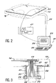
- the system comprises an optical device 20 (FIG. 2), a control console 21 and an electrical connection cable 22.
- the control console of the system is in fact that of the radiological installation such as a mammograph of which the system is a part. according to the invention and it comprises in particular a computer 23 with a screen 24 and a keyboard 25.
- the optical device 20 comprises (FIGS. 3, 4 and 5) a display module 26 and a bundle 27 of optical fibers 28 which are held on the same support 29 in a fixed geometric relationship.
- the display module 26 is of all known types and in particular that manufactured by the company ISE ELECTRONICS CORPORATION and sold under the brand ITRON by the company NORITAKE EUROPA GmbH.
- Such a display module includes not only the fluorescent type display screen, but also the control circuit for the elementary light points or pixels to generate the characters. It is this control circuit which is connected by the connecting cable 22 to the control console 21.
- each character is created using an elementary matrix of 16 pixels by 16 pixels, the screen comprising as many elementary matrices as the maximum number of characters to be created.
- the screen therefore comprises elementary matrices arranged in rows and columns and each elementary matrix being itself organized in rows and columns of pixels referenced 30.
- the purpose of the bundle 27 of optical fibers 28 is to transmit the light coming, for example, from an elementary matrix and therefore from a character, towards the radiological film to be impressed but with reduction of the size of the character by reduction of the dimensions of the optical fiber 28. This reduction can be in the ratio of 2 to 1.
- a bundle of fibers is thus obtained, the end of the x-ray film side (exit face of the bundle) has a much smaller area than that of the display screen and which is adapted to the useful area of the area to be impressed.
- the exit face of the bundle of optical fibers has an area which is adapted to that of the useful area of the radiological film whatever the type of cassette.
- an optical fiber with each pixel or with a group of pixels and reduce the diameter of said fiber as the pixel or group of pixels moves away.
- the optical device 20 is provided so as to be light-tight and to allow movements in the horizontal plane (double arrows 31 and 32) and in the vertical direction (double arrow 33).
- the display module 26 is supported by an external frame 34, the lateral extensions of which fit into grooves or slides 35 and 36 in which they can slide in the directions indicated by the double arrows 31 and 32.
- the grooves 35 and 36 are each mounted respectively at the end of arms 37 and 38 which slide vertically (double arrow 33) in slides (not shown) carried by sides 39 and 40 which are integral with the upper wall 41 of the plate 13 on which the cassette 18 rests.
- the horizontal slides 35 and 36 are provided for allow sufficient amplitudes of the horizontal movements in order to adapt to the position of the useful printing area on the radiological film.
- the vertical slides are provided to allow the optical device to be retracted into the plate 13 during the positioning of the cassette 18 and its positioning as close as possible to the radiological film 14 for printing, preferably in contact with the latter.
- a spring 45 working in compression, is arranged between the sides 39.40 and the arms 37.38 to bring the exit face of the optical beam 27 towards the radiological film 14.
- the vertical movements of the optical device are combined with the opening and closing movements of a shutter 42 which closes the access window to the useful area of the radiological film 14 after the cassette 18 has been put in place.
- the different movements of the optical device are obtained by micro-motors (not shown) which are controlled by the computer 23 according to the type of cassette used.
- the operating mode and operation of the radiological film printing system are then as follows.
- the practitioner indicates the information to be recorded such as the patient's last name, first name and date of birth, the type of radiological view, the operating characteristics of the radiological apparatus, the date of the examination.
- the cassette is placed on the plate 13 and the practitioner indicates by the keyboard to the computer the type of this cassette, which allows the computer to determine the horizontal displacements and vertical of the optical device according to the characteristics of the previously recorded cassette.
- the computer then sends on the cable 22 appropriate control signals from the micro-motors so that the exit face of the bundle 27 of optical fibers comes into contact with the radiological film 14 after opening the shutter 42 and at the best position in the area. useful reserved for printing data.
- the rectangle 45 in FIG. 2 shows an example of information which can be entered on the radiological film via the system and the device according to the invention.
- the invention has been described with a bundle 27 of optical fibers 28 between the display module 26 and the film which is short and which is rigid.
- the invention is also applicable to the case where this bundle 27 of fibers is longer, which makes it possible to place the display module 26 at another location than on the shelf 13, for example on the column 12 (FIG. 1 ).
- the support device 29 is only intended to hold and move the end of the fiber bundle, that is to say the outlet face.
- the bundle (27) of fibers must be flexible to adapt to the relative positions of the column 12 and the shelf 13 and its outlet face must be maintained by means of a device which is similar to the device. 20 but quine will not include the display module 26.
Abstract
Description
L'invention concerne les installations de radiologie et, plus particulièrement dans de telles installations, les systèmes et dispositifs qui permettent d'enregistrer sur le cliché radiologique des informations d'identification concernant ce cliché et la personne à laquelle il correspond.The invention relates to radiology installations and, more particularly in such installations, systems and devices which make it possible to record on the radiographic image identification information relating to this image and the person to whom it corresponds.
L'invention sera décrite dans son application à des systèmes de radiologie du type mammographe qui comprennent, comme le montre la figure 1, une source 10 de rayonnement X portée par une potence 11 disposée au sommet d'une plaque verticale 12. Cette dernière comporte un ensemble 13 sur lequel repose le sein 16 à examiner par l'intermédiaire d'une tablette horizontale 15. Une pelote 17, transparente au rayonnement X et mobile verticalement sur la plaque 12, sert à comprimer le sein.The invention will be described in its application to radiology systems of the mammography type which comprise, as shown in FIG. 1, a
Pour s'adapter à la taille de la patiente, la plaque 12 est montée sur une colonne verticale 9 reposant sur le sol et se déplace verticalement sur ladite colonne grâce à un dispositif mécanique approprié.To adapt to the size of the patient, the
L'ensemble 13 présente, sur sa partie supérieure et sous la tablette 15, un tunnel dans lequel vient se loger une cassette 18 constituée d'une boîte noire renfermant un film 14 sensible au rayonnement X direct ou à un rayonnement photonique émis par un écran (non représenté) recevant le rayonnement X. C'est sur ce film 14 que se forme l'image latente du sein après une durée de pose appropriée; le développement du film donne un cliché radiographique.The
D'une manière générale, il est important d'assurer, au fur et à mesure des examens radiologiques, le suivi de l'histoire médicale du patient et, à cet effet, l'identification des clichés est nécessaire : nom et âge du patient, date de l'examen, vue réalisée, nom du praticien, constantes radiologiques utilisées (haute tension, grandissement, dose), ces dernières n'étant connues qu'après l'examen et étant fournies par l'appareil radiologique...Ce suivi est encore plus important dans les examens préventifs, notamment en mammographie, où il est indispensable de déterminer l'évolution temporelle et spatiale des affections qui peuvent affliger l'organe radiographié.In general, it is important to ensure, at the as and when radiological examinations, monitoring of the patient's medical history and, for this purpose, identification of pictures is necessary: name and age of the patient, date of the examination, view performed, name of the practitioner, radiological constants used (high voltage, magnification, dose), the latter being known only after the examination and being provided by the radiological apparatus ... This monitoring is even more important in preventive examinations, in particular in mammography, where it is essential to determine the temporal and spatial evolution of the affections which can afflict the radiographed organ.
Il existe de nombreux procédés d'identification des clichés qui consistent, de manière générale, à inscrire les informations ou indications souhaitées sur une portion du film radiologique non encore développé et hors de l'image de l'organe radiographié. Cette inscription est réalisée simultanément au cliché de l'organe, c'est le procédé direct, ou après la réalisation dudit cliché, c'est le procédé indirect.There are many methods of identifying photographs which generally consist of writing the desired information or indications on a portion of the radiological film not yet developed and outside the image of the radiographed organ. This registration is carried out simultaneously with the image of the organ, it is the direct method, or after the realization of said image, it is the indirect method.
Dans le procédé direct, un ensemble de caractères reproduisant les données à marquer sont placés dans le champ des rayons X et apparaissent donc sur une portion déterminée du cliché radiologique après développement. Ils peuvent apparaître en blanc sur fond noir (mode négatif) dans le cas où les caractères sont opaques au rayonnement X, c'est l'impression par absorption, ou en noir sur fond blanc (mode positif) dans le cas où les caractères sont transparents au rayonnement X, c'est l'impression par transmission.In the direct process, a set of characters reproducing the data to be marked are placed in the X-ray field and therefore appear on a determined portion of the radiograph after development. They can appear in white on a black background (negative mode) in the case where the characters are opaque to X-rays, this is printing by absorption, or in black on a white background (positive mode) in the case where the characters are transparent to X-rays, this is printing by transmission.
Dans le procédé indirect, la portion du film radiologique, réservée aux informations, n'est pas impressionnée pendant l'examen, soit qu'elle se trouve en dehors du champ du rayonnement X, soit qu'elle est protégée par un masque opaque au rayonnement X si elle se trouve dans le champ du rayonnement X. Après la radiographie, la cassette, contenant le film radiologique non développé, est introduite dans un dispositif autonome, séparé de l'appareil radiologique, qui peut aussi faire partie intégrante du système de développement, pour l'impression des caractères. Cette impression peut être réalisée par un rayonnement X comme dans le procédé direct ou, le plus souvent, par un rayonnement lumineux dont la longueur d'onde est appropriée au film radiologique, c'est le cas des cassettes du type film-écran signalées ci-dessus.In the indirect process, the portion of the radiological film, reserved for information, is not impressed during the examination, either because it is outside the X-ray field, or because it is protected by an X-ray opaque mask if it is in the X-ray field. After the radiography, the cassette, containing the undeveloped radiological film, is introduced into an autonomous device, separate from the radiological apparatus, which can also be an integral part of the development system, for printing characters. This printing can be carried out by X-ray as in the direct process or, more often, by light radiation whose wavelength is suitable for the radiological film, this is the case of cassettes of the screen-film type indicated here. -above.
Dans ce dernier cas, la cassette présente une fenêtre mobile en vis-à-vis de la zone masquée du côté opposé à celui de la source de rayonnement X. Le dispositif d'impression doit alors réaliser les opérations suivantes : étanchéité à la lumière dans la zone de la fenêtre, ouverture de la fenêtre, impression des données, fermeture de la fenêtre.In the latter case, the cassette has a movable window facing the masked area on the side opposite that of the X-ray source. The printing device must then carry out the following operations: airtightness in the window area, opening the window, printing data, closing the window.
Dans les systèmes de développement avec marquage intégré, le film radiologique est ensuite retiré de la cassette pour être introduit dans le circuit de révélation et de fixation du cliché, à la sortie duquel ce dernier présente l'image de l'organe radiographié et les données d'identification.In development systems with integrated marking, the radiological film is then removed from the cassette to be introduced into the exposure and fixation circuit of the radiograph, at the outlet of which the latter presents the image of the radiographed organ and the data identification.
Dans le cas où l'impression des données d'identification est réalisée avec la lumière, une carte sur laquelle est inscrite le texte souhaité est interposé entre la source de lumière et le film radiologique. Les caractères du texte sont soit écrits sur papier transparent pour obtenir des lettres blanches sur fond noir (mode négatif), soit écrits sous forme de perforation sur une carte opaque au rayonnement lumineux pour obtenir des lettres noires sur fond blanc (mode positif). Dans certains dispositifs de marquage, certaines données, en nombre restreint, telles que la date et/ou l'heure, sont inscrites à partir d'un dispositif analogue à celui d'une montre digitale.In the case where the identification data is printed with light, a card on which the desired text is written is interposed between the light source and the radiological film. The characters of the text are either written on transparent paper to obtain white letters on a black background (negative mode), or written in the form of a perforation on an opaque card with light radiation to obtain black letters on a white background (positive mode). In certain marking devices, certain data, in limited numbers, such as the date and / or time, are recorded using a device similar to that of a digital watch.
Les procédés d'impression de données d'identification de films radiologiques qui viennent d'être décrits succinctement ont chacun leurs avantages et inconvénients et le choix entre l'un ou l'autre procédé résulte d'un compromis qui tient compte notamment du type d'examen radiologique, du type de film radiologique et de la place disponible pour enregistrer les données d'identification.The methods of printing identification data of radiological films which have just been described briefly each have their advantages and disadvantages and the choice between one or the other method results from a compromise which takes into account in particular the type of radiological examination, the type of radiological film and the space available to record the identification data.
Ainsi, dans le cas de la mammographie, le film radiologique étant sensible au rayonnement lumineux c'est le procédé d'impression des caractères du texte par la lumière qui est habituellement choisi. Mais la longueur de ce texte est limité car la zone du film qui lui est réservée est petite. En outre, comme cette zone est plus petite que la carte contenant le texte, il faut prévoir un dispositif optique approprié pour projeter le texte inscrit ou perforé sur ladite zone du film.Thus, in the case of mammography, the radiological film being sensitive to light radiation it is the method of printing the characters of the text by light which is usually chosen. But the length of this text is limited because the area of the film reserved for it is small. In addition, as this zone is smaller than the card containing the text, it is necessary to provide an appropriate optical device for projecting the text inscribed or perforated on said zone of the film.
Par ailleurs, les faibles dimensions de cette zone d'impression ne permettent pas l'utilisation directe sans adaptation de modules d'affichage du type à cristaux liquides ou autres.Furthermore, the small dimensions of this printing area do not allow direct use without adaptation of display modules of the liquid crystal or other type.
Enfin, les dimensions de la zone d'impression et celles de la fenêtre et sa position précise sur le film ou par rapport au plan de la cassette ne sont pas normalisées et varient donc d'un fabricant à l'autre, de sorte que chaque fabricant propose son propre dispositif d'impression quine peut pas être intégré à l'appareil de radiologie sans introduire des modifications importantes, soit pour le mettre en place, soit pour recueillir les paramètres radiologiques de l'appareil de radiologie.Finally, the dimensions of the printing area and those of the window and its precise position on the film or in relation to the plane of the cassette are not standardized and therefore vary from one manufacturer to another, so that each manufacturer offers his own printing device which cannot be integrated into the radiology device without introducing significant modifications, either to set it up or to collect the radiological parameters of the radiology device radiology.
Un but de la présente invention est donc de réaliser un système et un dispositif d'impression d'informations sur un film radiologique du type sensible à la lumière qui sont adaptables aux différentes cassettes des fabricants.An object of the present invention is therefore to provide a system and a device for printing information on an X-ray film of the light-sensitive type which are adaptable to the various cassettes of the manufacturers.
Un autre but de l'invention est aussi de réaliser un tel système et un tel dispositif d'impression en mettant en oeuvre des modules d'affichage lumineux du type programmable et à commande par calculateur.Another object of the invention is also to produce such a system and such a printing device by using light display modules of the programmable type and controlled by a computer.
Encore un autre but de l'invention est un système et un dispositif d'impression qui permettent l'enregistrement d'informations lorsque le patient est encore en place sur l'appareil de radiologie tel qu'un mammographe.Yet another object of the invention is a system and a printing device which allow recording of information when the patient is still in place on the radiology device such as a mammograph.
L'invention concerne un système d'impression d'informations sur un film radiologique sensible à la lumière qui est disposé dans une cassette, ledit film comportant une zone pour l'impression d'informations qui est protégée du rayonnement X par un masque porté par la cassette et qui est accessible pour l'impression par une fenêtre fermée par un volet mobile également porté par la cassette, ledit système étant caractérisé par le fait qu'il comprend un dispositif optique mobile coopérant avec la fenêtre et le volet de ladite cassette et comportant au moins un module d'affichage lumineux, des moyens motorisés pour déplacer ledit dispositif optique suivant trois axes orthogonaux, et un ordinateur pour commander, d'une part, ledit module d'affichage pour qu'il affiche les informations à transférer sur ladite zone du film radiologique et, d'autre part, les moyens motorisés pour que la face de sortie dudit dispositif optique vienne au contact du film radiologique en vue de son impression.The invention relates to a system for printing information on a light-sensitive radiological film which is placed in a cassette, said film comprising an area for printing information which is protected from X-radiation by a mask worn by the cassette and which is accessible for printing by a window closed by a movable flap also carried by the cassette, said system being characterized in that it comprises a mobile optical device cooperating with the window and the flap of said cassette and comprising at least one light display module, motorized means for moving said optical device along three orthogonal axes, and a computer for controlling, on the one hand, said display module so that it displays the information to be transferred on said area of the radiological film and, on the other hand, the motorized means so that the outlet face of said optical device comes into contact with the radiological film with a view to e his impression.
Afin d'adapter les dimensions de l'écran du module d'affichage à celles de la zone à impressionner, la lumière émise par l'écran dudit module est transmise vers ladite zone par l'intermédiaire d'un faisceau de fibres optiques dont le diamètre de la face de sortie qui vient en contact avec le film radiologique est plus petit que celui de la face d'entrée de la lumière provenant dudit module d'affichage.In order to adapt the dimensions of the module screen display to those of the area to be impressed, the light emitted by the screen of said module is transmitted to said area via a bundle of optical fibers, the diameter of the outlet face of which comes into contact with the X-ray film is smaller than that of the input face of the light from said display module.
Les moyens motorisés pour déplacer le dispositif optique permettent le positionnement précis de la face de sortie du faisceau de fibres par rapport à la zone du film radiologique à impressionner de manière à s'adapter aux différents types de cassettes utilisées.The motorized means for moving the optical device allow the precise positioning of the exit face of the fiber bundle relative to the area of the radiological film to be impressed so as to adapt to the different types of cassettes used.
D'autres caractéristiques et avantages de la présente invention apparaîtront à, la lecture de la description suivante d'un exemple particulier de réalisation, ladite description étant faite en relation avec les dessins joints dans lesquels :
- la figure 1 est une vue en coupe verticale simplifiée d'un mammographe qui utilise des cassettes auxquelles s'applique le dispositif selon l'invention,
- la figure 2 est un schéma de principe d'un système d'impression d'informations sur film radiologique selon l'invention,
- la figure 3 est une vue en coupe du dispositif optique du système selon l'invention et,
- la figure 4 est une vue en perspective cavalière montrant le faisceau de fibres optiques utilisé dans le dispositif optique selon l'invention, et
- la figure 5 est une vue en coupe et en perspective cavalière du dispositif optique monté sur les moyens de déplacement solidaire de la tablette de support de la cassette.
- FIG. 1 is a simplified vertical section view of a mammograph which uses cassettes to which the device according to the invention applies,
- FIG. 2 is a block diagram of a system for printing information on radiological film according to the invention,
- FIG. 3 is a sectional view of the optical device of the system according to the invention and,
- FIG. 4 is a perspective view showing the bundle of optical fibers used in the optical device according to the invention, and
- Figure 5 is a sectional view in perspective of the optical device mounted on the integral displacement means of the cassette support shelf.
Le système et le dispositif d'impression d'informations sur un film radiologique selon l'invention seront décrits dans son application à un mammographe du type de celui de la figure 1 mais il peut être mis en oeuvre avec tout autre type d'appareil radiologique utilisant des cassettes ou en association avec un dispositif de développement des films radiologiques.The system and the device for printing information on a radiological film according to the invention will be described in its application to a mammograph of the type of that of FIG. 1 but it can be implemented with any other type of radiological device using cassettes or in association with a device for developing radiological films.
Le système comprend un dispositif optique 20 (figure 2), un pupitre de commande 21 et un câble électrique de liaison 22. Le pupitre de commande du système est en fait celui de l'installation radiologique tel qu'un mammographe dont fait partie le système selon l'invention et il comprend notamment un ordinateur 23 avec un écran 24 et un clavier 25.The system comprises an optical device 20 (FIG. 2), a
Le dispositif optique 20 comprend (figures 3,4 et 5) un module d'affichage 26 et un faisceau 27 de fibres optiques 28 qui sont maintenues sur un même support 29 dans une relation géométrique fixe. Le module d'affichage 26 est de tous types connus et notamment celui fabriqué par la société ISE ELECTRONICS CORPORATION et vendu sous la marque ITRON par la société NORITAKE EUROPA GmbH. Un tel module d'affichage comprend, non seulement l'écran d'affichage du type fluorescent, mais aussi le circuit de commande des points lumineux élémentaires ou pixels pour générer les caractères. C'est ce circuit de commande qui est connecté par le câble de liaison 22 au pupitre de commande 21.The
Par exemple, chaque caractère est créé à l'aide d'une matrice élémentaire de 16 pixels par 16 pixels, l'écran comportant autant de matrices élémentaires que de nombre maximum de caractères à créer. L'écran comprend donc des matrices élémentaires arrangés en lignes et colonnes et chaque matrice élémentaire étant elle-même organisée en lignes et colonnes de pixels référencés 30.For example, each character is created using an elementary matrix of 16 pixels by 16 pixels, the screen comprising as many elementary matrices as the maximum number of characters to be created. The screen therefore comprises elementary matrices arranged in rows and columns and each elementary matrix being itself organized in rows and columns of pixels referenced 30.
Le faisceau 27 de fibres optiques 28 a pour but de transmettre la lumière provenant, par exemple, d'une matrice élémentaire et donc d'un caractère, vers le film radiologique à impressionner mais avec réduction de la taille du caractère par réduction des dimensions de la fibre optique 28. Cette réduction peut être dans le rapport de 2 à 1. On obtient ainsi un faisceau de fibres dont l'extrémité du côté film radiologique (face de sortie du faisceau) a une superficie nettement moindre que celle de l'écran d'affichage et qui est adaptée à la superficie utile de la zone à impressionner.The purpose of the
La face de sortie du faisceau de fibres optiques a une superficie qui est adaptée à celle de la zone utile du film radiologique quel que soit le type de cassette. Bien entendu, il est possible d'associer une fibre optique à chaque pixel ou à un groupe de pixels et de réduire le diamètre de ladite fibre au fur et à mesure de l'éloignement du pixel ou du groupe de pixels.The exit face of the bundle of optical fibers has an area which is adapted to that of the useful area of the radiological film whatever the type of cassette. Of course, it is possible to associate an optical fiber with each pixel or with a group of pixels and reduce the diameter of said fiber as the pixel or group of pixels moves away.
Le dispositif optique 20 est prévu de manière à être étanche à la lumière et à permettre des déplacements dans le plan horizontal (flèches doubles 31 et 32) et dans le sens vertical (flèche double 33).The
Pour obtenir ces effets, le module d'affichage 26 est supporté par un cadre extérieur 34 dont les prolongements latéraux s'emboîtent dans des rainures ou glissières 35 et 36 dans lesquelles ils peuvent coulisser suivant les directions indiquées par les flèches doubles 31 et 32. Les rainures 35 et 36 sont montées chacune respectivement à l'extrémité de bras 37 et 38 qui coulissent verticalement (flèche double 33) dans des glissières (non représentées) portées par des flancs 39 et 40 qui sont solidaires de la paroi supérieure 41 du plateau 13 sur laquelle repose la cassette 18.To obtain these effects, the
Les glissières horizontales 35 et 36 sont prévues pour permettre des amplitudes suffisantes des mouvements horizontaux afin de s'adapter à la position de la zone utile d'impression sur le film radiologique. Les glissières verticales sont prévues pour permettre l'escamotage du dispositif optique dans le plateau 13 lors de la mise en place de la cassette 18 et son positionnement du plus près du film radiologique 14 pour l'impression, de préférence au contact de ce dernier. Un ressort 45, travaillant en compression, est disposé entre les flancs 39,40 et les bras 37,38 pour ramener la face de sortie du faisceau optique 27 vers le film radiologique 14.The
Les déplacements verticaux du dispositif optique sont combinés avec les déplacements d'ouverture et de fermeture d'un volet 42 qui obture la fenêtre d'accès à la zone utile du film radiologique 14 après mise en place de la cassette 18.The vertical movements of the optical device are combined with the opening and closing movements of a
Les différents déplacements du dispositif optique sont obtenus par des micro-moteurs (non représentés) qui sont commandés par l'ordinateur 23 en fonction du type de cassette utilisé.The different movements of the optical device are obtained by micro-motors (not shown) which are controlled by the
Le mode opératoire et le fonctionnement du système d'impression sur film radiologique sont alors les suivants. A l'aide du clavier 25, le praticien indique les informations à enregistrer telles que les nom, prénom et date de naissance du patient, le type de vue radiologique, les caractéristiques opératives de l'appareil radiologique, la date de l'examen. Lorsque ces informations sont prêtes à l'enregistrement, la cassette est mise en place sur le plateau 13 et le praticien indique par le clavier à l'ordinateur le type de cette cassette, ce qui permet à l'ordinateur de déterminer les déplacements horizontaux et verticaux du dispositif optique en fonction des caractéristiques de la cassette préalablement enregistrées. L'ordinateur envoie alors sur le câble 22 des signaux de commande appropriés des micro-moteurs pour que la face de sortie du faisceau 27 de fibres optiques vienne en contact du film radiologique 14 après ouverture du volet 42 et à la meilleure position dans la zone utile réservée à l'impression des données. Lorsque le dispositif optique est en place, le praticien peut commander l'impression des informations écrites sur l'écran 24 par affichage sur l'écran du module 26. Le rectangle 45 de la figure 2 montre un exemple d'informations qui peuvent être inscrites sur le film radiologique par l'intermédiaire système et du dispositif selon l'invention.The operating mode and operation of the radiological film printing system are then as follows. Using the
L'invention a été décrite avec un faisceau 27 de fibres optiques 28 entre le module d'affichage 26 et le film qui est de faible longueur et qui est rigide. Cependant, l'invention est également applicable au cas où ce faisceau 27 de fibres est plus long, ce qui permet de placer le module d'affichage 26 à un autre endroit que sur la tablette 13, par exemple sur la colonne 12 (figure 1). Dans ce cas, le dispositif de support 29 n'est prévu que pour maintenir et déplacer l'extrémité du faisceau de fibres, c'est-à-dire la face de sortie. En outre, le faisceau (27) de fibres doit être souple pour s'adapter aux positions relatives de la colonne 12 et de la tablette 13 et sa face de sortie doit être maintenue par l'intermédiaire d'un dispositif qui est semblable au dispositif 20 mais quine comprendra pas le module d'affichage 26.The invention has been described with a
Claims (6)
Applications Claiming Priority (2)
| Application Number | Priority Date | Filing Date | Title |
|---|---|---|---|
| FR9011088A FR2666500B1 (en) | 1990-09-06 | 1990-09-06 | SYSTEM AND DEVICE FOR PRINTING INFORMATION ON RADIOLOGICAL FILMS. |
| FR9011088 | 1990-09-06 |
Publications (1)
| Publication Number | Publication Date |
|---|---|
| EP0474552A1 true EP0474552A1 (en) | 1992-03-11 |
Family
ID=9400136
Family Applications (1)
| Application Number | Title | Priority Date | Filing Date |
|---|---|---|---|
| EP91402358A Withdrawn EP0474552A1 (en) | 1990-09-06 | 1991-09-03 | System and device for recording information on X-ray films |
Country Status (2)
| Country | Link |
|---|---|
| EP (1) | EP0474552A1 (en) |
| FR (1) | FR2666500B1 (en) |
Cited By (4)
| Publication number | Priority date | Publication date | Assignee | Title |
|---|---|---|---|---|
| FR2697925A1 (en) * | 1992-11-10 | 1994-05-13 | Gen Electric Cgr | Printing head for marking radiographic films - uses groups of seven optical fibres displaced by stepper motors to produce alphanumeric characters |
| EP0679937A2 (en) * | 1994-04-14 | 1995-11-02 | Agfa-Gevaert N.V. | Material and method for printing radiological images |
| WO2005106580A1 (en) * | 2004-04-28 | 2005-11-10 | Siemens Aktiengesellschaft | System for x-ray examination in particular for analogue mammography |
| US7869575B2 (en) | 2004-04-28 | 2011-01-11 | Siemens Aktiengesellschaft | X-ray examination system for analog mammography |
Citations (6)
| Publication number | Priority date | Publication date | Assignee | Title |
|---|---|---|---|---|
| FR1470037A (en) * | 1966-02-24 | 1967-02-17 | Integrated tracking indexing device for X-ray images | |
| US4222145A (en) * | 1977-11-02 | 1980-09-16 | Clarke-Gravely Corporation | Vacuum cleaner carriage and tank assembly |
| DE3633289A1 (en) * | 1986-09-30 | 1988-03-31 | Siemens Ag | Dental device |
| US4797691A (en) * | 1986-08-13 | 1989-01-10 | Fuji Photo Film Co., Ltd. | Side printing head assembly |
| WO1989006377A1 (en) * | 1987-12-29 | 1989-07-13 | B.V. Optische Industrie 'de Oude Delft' | System for recording data on an x-ray film fitted in a cassette |
| EP0336836A1 (en) * | 1988-04-08 | 1989-10-11 | Iconos | Apparatus to optically form information on a radiographic film in a cassette |
-
1990
- 1990-09-06 FR FR9011088A patent/FR2666500B1/en not_active Expired - Lifetime
-
1991
- 1991-09-03 EP EP91402358A patent/EP0474552A1/en not_active Withdrawn
Patent Citations (6)
| Publication number | Priority date | Publication date | Assignee | Title |
|---|---|---|---|---|
| FR1470037A (en) * | 1966-02-24 | 1967-02-17 | Integrated tracking indexing device for X-ray images | |
| US4222145A (en) * | 1977-11-02 | 1980-09-16 | Clarke-Gravely Corporation | Vacuum cleaner carriage and tank assembly |
| US4797691A (en) * | 1986-08-13 | 1989-01-10 | Fuji Photo Film Co., Ltd. | Side printing head assembly |
| DE3633289A1 (en) * | 1986-09-30 | 1988-03-31 | Siemens Ag | Dental device |
| WO1989006377A1 (en) * | 1987-12-29 | 1989-07-13 | B.V. Optische Industrie 'de Oude Delft' | System for recording data on an x-ray film fitted in a cassette |
| EP0336836A1 (en) * | 1988-04-08 | 1989-10-11 | Iconos | Apparatus to optically form information on a radiographic film in a cassette |
Non-Patent Citations (5)
| Title |
|---|
| CHEMICAL ABSTRACTS, vol. 23, no. 34, 3 Avril 1967, Columbus, Ohio, US; abstract no. 23456F, H.SIMSON: 'Atomic Energy' page 12 ;colonne 34 ; * |
| HIGHWAYS & PUBLIC WORKS vol. 23, no. 12, 4 Juillet 1978, LONDON GB pages 125 - 180; S. PEETERS: 'NEW MATERIALS IN MODERN BUILDINGS' * |
| JAPANESE PATENTS GAZETTE Section CH, week 8715, 27 May 1987 Derwent Publications Ltd., London GB * |
| P. WATSON 'SOCIAL LIFE AT THE EPO' 2 Mai 1979 , EPO-PRESS , THE HAGUE NL * |
| PATENT ABSTRACTS OF JAPAN vol. 3, no. 49 (M-57)(2347) 26 Avril 1979 & JP-A-54 028 467 ( HITACHI ) 3 Mars 1979 * |
Cited By (4)
| Publication number | Priority date | Publication date | Assignee | Title |
|---|---|---|---|---|
| FR2697925A1 (en) * | 1992-11-10 | 1994-05-13 | Gen Electric Cgr | Printing head for marking radiographic films - uses groups of seven optical fibres displaced by stepper motors to produce alphanumeric characters |
| EP0679937A2 (en) * | 1994-04-14 | 1995-11-02 | Agfa-Gevaert N.V. | Material and method for printing radiological images |
| WO2005106580A1 (en) * | 2004-04-28 | 2005-11-10 | Siemens Aktiengesellschaft | System for x-ray examination in particular for analogue mammography |
| US7869575B2 (en) | 2004-04-28 | 2011-01-11 | Siemens Aktiengesellschaft | X-ray examination system for analog mammography |
Also Published As
| Publication number | Publication date |
|---|---|
| FR2666500B1 (en) | 1994-01-07 |
| FR2666500A1 (en) | 1992-03-13 |
Similar Documents
| Publication | Publication Date | Title |
|---|---|---|
| US5288977A (en) | System for imprinting patient-identifying barcodes onto medical X-rays | |
| EP0928438B1 (en) | Detachable device for radiological digital imaging | |
| US7103140B2 (en) | Radiation image radiographic apparatus | |
| JP2005073706A (en) | X-ray image photography apparatus | |
| US5543874A (en) | Instant printer for volumetric imaging of data from electromagnetic radiation output device | |
| JPS62227139A (en) | Method and apparatus for recording on film of panoramic typex-rays tomograph | |
| EP0474552A1 (en) | System and device for recording information on X-ray films | |
| JPH0544824Y2 (en) | ||
| JPH0476266B2 (en) | ||
| Artz | Computed radiography for the radiological technologist | |
| EP1137966B1 (en) | Apparatus and method for positioning a digital x-ray detector array | |
| JPH05273677A (en) | Device and method for patient information | |
| FR2463429A1 (en) | INSTALLATION FOR THE TAKING AND DEVELOPMENT OF RADIOGRAPHIC CLIPS | |
| JP3946895B2 (en) | Stable phosphor sheet cassette | |
| US2511097A (en) | Device for obtaining x-ray | |
| JP3645559B2 (en) | Medical digital X-ray imaging apparatus, X-ray imaging system, and method for imaging X-ray fluorescence image as digital data | |
| US4167672A (en) | Method and apparatus for demonstration of arbitrary surfaces with dynamic tomography | |
| KR910005732A (en) | X-ray film processing method, X-ray film photography device, and X-ray film information processing device | |
| WO2012125244A2 (en) | Computed radiography scanner and envelope for imaging plates | |
| JPH0670704B2 (en) | Film cassette | |
| Raikes | Floral radiography: using x rays to create fine art | |
| JPH02299640A (en) | X-ray diagnostic apparatus | |
| FR2697925A1 (en) | Printing head for marking radiographic films - uses groups of seven optical fibres displaced by stepper motors to produce alphanumeric characters | |
| Carter et al. | Digital Radiography and PACS E-Book: Digital Radiography and PACS E-Book | |
| JPH01270045A (en) | Film cassette |
Legal Events
| Date | Code | Title | Description |
|---|---|---|---|
| PUAI | Public reference made under article 153(3) epc to a published international application that has entered the european phase |
Free format text: ORIGINAL CODE: 0009012 |
|
| AK | Designated contracting states |
Kind code of ref document: A1 Designated state(s): DE NL |
|
| 17P | Request for examination filed |
Effective date: 19920406 |
|
| 17Q | First examination report despatched |
Effective date: 19930818 |
|
| STAA | Information on the status of an ep patent application or granted ep patent |
Free format text: STATUS: THE APPLICATION IS DEEMED TO BE WITHDRAWN |
|
| 18D | Application deemed to be withdrawn |
Effective date: 19931229 |