EP0474532A1 - Riemenspanner für einen Nockenwellenantrieb eines Fahrzeugmotors - Google Patents
Riemenspanner für einen Nockenwellenantrieb eines Fahrzeugmotors Download PDFInfo
- Publication number
- EP0474532A1 EP0474532A1 EP91402271A EP91402271A EP0474532A1 EP 0474532 A1 EP0474532 A1 EP 0474532A1 EP 91402271 A EP91402271 A EP 91402271A EP 91402271 A EP91402271 A EP 91402271A EP 0474532 A1 EP0474532 A1 EP 0474532A1
- Authority
- EP
- European Patent Office
- Prior art keywords
- belt
- tensioner
- roller
- lever
- actuator
- Prior art date
- Legal status (The legal status is an assumption and is not a legal conclusion. Google has not performed a legal analysis and makes no representation as to the accuracy of the status listed.)
- Granted
Links
Images

Classifications
-
- F—MECHANICAL ENGINEERING; LIGHTING; HEATING; WEAPONS; BLASTING
- F16—ENGINEERING ELEMENTS AND UNITS; GENERAL MEASURES FOR PRODUCING AND MAINTAINING EFFECTIVE FUNCTIONING OF MACHINES OR INSTALLATIONS; THERMAL INSULATION IN GENERAL
- F16H—GEARING
- F16H7/00—Gearings for conveying rotary motion by endless flexible members
- F16H7/08—Means for varying tension of belts, ropes or chains
- F16H7/10—Means for varying tension of belts, ropes or chains by adjusting the axis of a pulley
- F16H7/12—Means for varying tension of belts, ropes or chains by adjusting the axis of a pulley of an idle pulley
- F16H7/1254—Means for varying tension of belts, ropes or chains by adjusting the axis of a pulley of an idle pulley without vibration damping means
- F16H7/1281—Means for varying tension of belts, ropes or chains by adjusting the axis of a pulley of an idle pulley without vibration damping means where the axis of the pulley moves along a substantially circular path
-
- F—MECHANICAL ENGINEERING; LIGHTING; HEATING; WEAPONS; BLASTING
- F16—ENGINEERING ELEMENTS AND UNITS; GENERAL MEASURES FOR PRODUCING AND MAINTAINING EFFECTIVE FUNCTIONING OF MACHINES OR INSTALLATIONS; THERMAL INSULATION IN GENERAL
- F16H—GEARING
- F16H7/00—Gearings for conveying rotary motion by endless flexible members
- F16H7/08—Means for varying tension of belts, ropes or chains
- F16H2007/0863—Finally actuated members, e.g. constructional details thereof
- F16H2007/087—Sprockets
-
- F—MECHANICAL ENGINEERING; LIGHTING; HEATING; WEAPONS; BLASTING
- F16—ENGINEERING ELEMENTS AND UNITS; GENERAL MEASURES FOR PRODUCING AND MAINTAINING EFFECTIVE FUNCTIONING OF MACHINES OR INSTALLATIONS; THERMAL INSULATION IN GENERAL
- F16H—GEARING
- F16H7/00—Gearings for conveying rotary motion by endless flexible members
- F16H7/08—Means for varying tension of belts, ropes or chains
- F16H2007/0876—Control or adjustment of actuators
- F16H2007/0878—Disabling during transport
-
- F—MECHANICAL ENGINEERING; LIGHTING; HEATING; WEAPONS; BLASTING
- F16—ENGINEERING ELEMENTS AND UNITS; GENERAL MEASURES FOR PRODUCING AND MAINTAINING EFFECTIVE FUNCTIONING OF MACHINES OR INSTALLATIONS; THERMAL INSULATION IN GENERAL
- F16H—GEARING
- F16H7/00—Gearings for conveying rotary motion by endless flexible members
- F16H7/08—Means for varying tension of belts, ropes or chains
- F16H2007/0876—Control or adjustment of actuators
- F16H2007/088—Manual adjustment
-
- F—MECHANICAL ENGINEERING; LIGHTING; HEATING; WEAPONS; BLASTING
- F16—ENGINEERING ELEMENTS AND UNITS; GENERAL MEASURES FOR PRODUCING AND MAINTAINING EFFECTIVE FUNCTIONING OF MACHINES OR INSTALLATIONS; THERMAL INSULATION IN GENERAL
- F16H—GEARING
- F16H7/00—Gearings for conveying rotary motion by endless flexible members
- F16H7/08—Means for varying tension of belts, ropes or chains
- F16H2007/0889—Path of movement of the finally actuated member
- F16H2007/0897—External to internal direction
-
- F—MECHANICAL ENGINEERING; LIGHTING; HEATING; WEAPONS; BLASTING
- F16—ENGINEERING ELEMENTS AND UNITS; GENERAL MEASURES FOR PRODUCING AND MAINTAINING EFFECTIVE FUNCTIONING OF MACHINES OR INSTALLATIONS; THERMAL INSULATION IN GENERAL
- F16H—GEARING
- F16H7/00—Gearings for conveying rotary motion by endless flexible members
- F16H7/08—Means for varying tension of belts, ropes or chains
- F16H7/0829—Means for varying tension of belts, ropes or chains with vibration damping means
Definitions
- the present invention relates to a belt tensioner in particular of a distribution system of a motor vehicle engine.
- the tensioning of the belt is ensured by means of a static tension roller which, in most cases, is a roller whose mechanism tension is controlled by a system called eccentric, which is characterized by an eccentricity of its axis of rotation relative to its axis of articulation.
- This type of roller is therefore able to ensure the tension of the belt during its installation, and to compensate for the static variations in the tension of the belt, which result from the difference between its theoretical pitch length to its actual pitch length.
- this type of tensioner is unable to compensate for the so-called dynamic variations in the tension of the belt, which result from the difference between the actual pitch length thereof and its primitive lengths, theoretical and actual, dilated ( engine running) and its own wear.
- the theoretical extended primitive length of a belt depends, considering it at the heat output terminals of the engine (-30 ° C, + 120 ° C), on its theoretical initial length indicated previously, while its actual expanded original length depends , by considering it at the heat output terminals of the engine, of its actual primitive length indicated above.
- a belt tensioner is known, in particular from a distribution system of a motor vehicle engine, of the type comprising an actuator and an eccentric tensioner roller, in which the roller is mounted eccentrically on the actuator and this assembly moves to make up for static play.
- the dynamic play is then caught up by rotation of the roller.
- the device described in this document has a certain number of drawbacks insofar as it does not make it possible to dissociate the roller and the actuator proper, which complicates the installation of this tensioner in an engine.
- the object of the invention is therefore to solve these problems by proposing a belt tensioner which can both make up for the static and dynamic play of a belt, and which is simple, reliable, with a low cost price, whose footprint is as small as possible and whose installation in an engine is as simple as possible.
- the subject of the invention is a belt tensioner, in particular a distribution system for a motor vehicle engine, of the type comprising an actuator and an eccentric tensioning roller, characterized in that the tensioning roller is disposed eccentrically.
- an operating lever the central part of which is articulated on a support plate, adapted to be fixed to the rest of the engine, and the other end of which is adapted to cooperate with the output rod of the actuator in order to control the position of the lever and therefore of the roller for tensioning said belt.
- said lever has the shape of an inverted V.
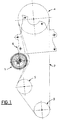
- FIG. 1 which represents a distribution diagram of a motor vehicle engine
- this comprises an eccentric tensioner 1 ensuring a tensioning presetting of a timing belt 2, making it possible to transmit the power supplied by a crankshaft 3 to other components of the vehicle, such as for example the camshaft pulley 4 and the pulley for controlling the water pump 5.
- this tensioner is unable to catch dynamic variations in belt tension and we are therefore obliged to add a dynamic tensioner.
- this tensioner 7 makes it possible to adjust the tension of a distribution belt 8 of the power delivered by a crankshaft 9 to the pulley 10 of an engine camshaft and to the control pulley of the water pump 11.
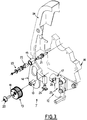
- this belt tensioner 7 comprises an actuator 12 of a type known per se and an eccentric tensioner roller 13.
- This eccentric tensioner roller 13 is disposed at the one end of an operating lever 14, the central part of which is articulated at 15, on a support plate 16 adapted to be fixed to the rest of the engine.
- the other end of this lever 14 is adapted to cooperate with the rod 17 of the actuator outlet in order to control the position of the lever relative to the plate and therefore the position of the roller to maintain the tension of the belt.
- the lever is mounted articulated at 15 relative to the support plate 16 by means of an articulation rod 21, around which a bronze bushing 22 can be arranged and at the end of which means are provided.
- holding position 23 comprising for example a screw.
- a cover 24 can also be fixed on the support plate 16 to protect the belt.
- the actuator is in fact an autonomous organ which can be assimilated to a shock absorber, consisting of a body 25 and the rod 17 which after removal of its retaining pin 26 and thanks to an internal mechanism, has a re-entrant stroke, by example of 4 mm and an outgoing stroke, for example 8 mm, from its initial position.
- This shock absorber can deploy a force for example of 10 DaN.
- the tensioner according to the invention gives the belt an almost constant tension, whatever the engine speed.
- the roller 13 is then brought into position using its eccentric mechanism until the lever 14 abuts against the output rod 17 of the actuator.
- the roller then acts as a winding roller which compensates for the static variations in belt tension and which can possibly attribute a slight pre-tension to this belt.
- the hub 18 of the roller is then tightened on the corresponding end of the lever 14 using the screw 20 and the retaining pin 26 is removed from the actuator output rod, so that the latter applies a force on the corresponding end of this lever, to bring the latter and therefore the roller in the tension position of the belt and compensation for dynamic variations in the tension thereof.
Landscapes
- Engineering & Computer Science (AREA)
- General Engineering & Computer Science (AREA)
- Mechanical Engineering (AREA)
- Devices For Conveying Motion By Means Of Endless Flexible Members (AREA)
Applications Claiming Priority (2)
| Application Number | Priority Date | Filing Date | Title |
|---|---|---|---|
| FR9011145A FR2666633B1 (fr) | 1990-09-07 | 1990-09-07 | Tendeur de courroie notamment d'un systeme de distribution d'un moteur de vehicule automobile. |
| FR9011145 | 1990-09-07 |
Publications (2)
| Publication Number | Publication Date |
|---|---|
| EP0474532A1 true EP0474532A1 (de) | 1992-03-11 |
| EP0474532B1 EP0474532B1 (de) | 1994-12-14 |
Family
ID=9400176
Family Applications (1)
| Application Number | Title | Priority Date | Filing Date |
|---|---|---|---|
| EP19910402271 Expired - Lifetime EP0474532B1 (de) | 1990-09-07 | 1991-08-20 | Riemenspanner für einen Nockenwellenantrieb eines Fahrzeugmotors |
Country Status (3)
| Country | Link |
|---|---|
| EP (1) | EP0474532B1 (de) |
| DE (1) | DE69105878T2 (de) |
| FR (1) | FR2666633B1 (de) |
Families Citing this family (1)
| Publication number | Priority date | Publication date | Assignee | Title |
|---|---|---|---|---|
| CN110701265B (zh) * | 2019-10-16 | 2021-10-08 | 徐州工业职业技术学院 | 一种横移式平行四杆带轮张紧机构 |
Citations (5)
| Publication number | Priority date | Publication date | Assignee | Title |
|---|---|---|---|---|
| US3060760A (en) * | 1959-04-06 | 1962-10-30 | Joy Mfg Co | Chain tensioning device |
| US3374686A (en) * | 1965-12-01 | 1968-03-26 | Brewer Machine & Gear Co | Drive-tensioning apparatus |
| US4713045A (en) * | 1985-09-30 | 1987-12-15 | Aisin Seiki Kabushiki Kaisha | Auto-tensioner for belt systems and a method for adjusting tension degree |
| DE3707917A1 (de) * | 1987-03-12 | 1988-09-22 | Skf Gmbh | Spannvorrichtung fuer treibriemen |
| FR2634531A1 (de) * | 1988-07-22 | 1990-01-26 | Ntn Toyo Bearing Co Ltd |
-
1990
- 1990-09-07 FR FR9011145A patent/FR2666633B1/fr not_active Expired - Fee Related
-
1991
- 1991-08-20 EP EP19910402271 patent/EP0474532B1/de not_active Expired - Lifetime
- 1991-08-20 DE DE1991605878 patent/DE69105878T2/de not_active Expired - Fee Related
Patent Citations (5)
| Publication number | Priority date | Publication date | Assignee | Title |
|---|---|---|---|---|
| US3060760A (en) * | 1959-04-06 | 1962-10-30 | Joy Mfg Co | Chain tensioning device |
| US3374686A (en) * | 1965-12-01 | 1968-03-26 | Brewer Machine & Gear Co | Drive-tensioning apparatus |
| US4713045A (en) * | 1985-09-30 | 1987-12-15 | Aisin Seiki Kabushiki Kaisha | Auto-tensioner for belt systems and a method for adjusting tension degree |
| DE3707917A1 (de) * | 1987-03-12 | 1988-09-22 | Skf Gmbh | Spannvorrichtung fuer treibriemen |
| FR2634531A1 (de) * | 1988-07-22 | 1990-01-26 | Ntn Toyo Bearing Co Ltd |
Also Published As
| Publication number | Publication date |
|---|---|
| EP0474532B1 (de) | 1994-12-14 |
| DE69105878T2 (de) | 1995-04-27 |
| FR2666633B1 (fr) | 1993-07-23 |
| FR2666633A1 (fr) | 1992-03-13 |
| DE69105878D1 (de) | 1995-01-26 |
Similar Documents
| Publication | Publication Date | Title |
|---|---|---|
| FR2535302A1 (fr) | Dispositif d'entrainement pour tambour a cable d'enroulement | |
| FR2833058A1 (fr) | Dispositif tendeur pour un entrainement par un moyen de traction d'un moteur a combustion interne | |
| EP0565402B1 (de) | Automatische Riemenspanner, insbesondere für Synchrontreibriemen, wie ein Riemen zur Ventilsteuerung einer Brennkraftmaschine | |
| FR2633689A1 (fr) | Dispositif de tension, notamment pour courroies de distribution de vehicules automobiles | |
| FR2759135A1 (fr) | Dispositif amortisseur de vibrations torsionnelles pour amortir les vibrations d'une ligne de transmission reliant un moteur aux roues motrices d'un vehicule | |
| FR2593750A1 (fr) | Generateur de chaleur a friction, notamment pour vehicule automobile | |
| EP0474532B1 (de) | Riemenspanner für einen Nockenwellenantrieb eines Fahrzeugmotors | |
| FR2698830A1 (fr) | Détecteur de position, dont l'organe de transmission est formé d'un organe d'actionnement. | |
| FR2832358A1 (fr) | Groupe motopropulseur pour vehicule automobile | |
| FR2796702A1 (fr) | Groupe motopropulseur comportant une entretoise de carter d'huile | |
| EP0505264B1 (de) | Winde für leicht beschädigbare Kabel | |
| EP0320327A1 (de) | Vorrichtung zur Befestigung eines ersten Teils, wie eines Zubehörs, an einem zweiten Teil, wie einem Träger, mit Nachstellhülse zum Ausgleichen des Zusammenbauspiels zwischen den beiden Teilen und Hülse für die Befestigung der beiden Teile | |
| FR2539834A1 (fr) | Frein a disque a etrier coulissant | |
| EP0495326B1 (de) | Riemenspannungseinstellvorrichtung für den Antrieb eines Kraftfahrzeugmotor-Zusatzaggregates | |
| FR2749902A1 (fr) | Procede d'assemblage et de reglage des elements d'un dispositif elastique d'amortissement | |
| EP0729885B1 (de) | Pneumatische Vorrichtung zur Verriegelung oder Entriegelung eines Rotors an einem Stator | |
| EP0838362A1 (de) | Anordnung eines elektronischen Gaspedals für Kraftfahrzeuge | |
| EP0452187B1 (de) | Vorrichtung zum hydraulischen automatischen Steuern des Förderbeginns | |
| FR2784155A1 (fr) | Amortisseur d'oscillations de torsion | |
| FR2569442A1 (fr) | Regulateur de vitesse de rotation pour des pompes d'injection de carburant | |
| EP0586304A1 (de) | Hydrodynamischer Drehmomentwandler mit Überbrückungskupplung und sein Montageverfahren | |
| FR2853033A1 (fr) | Entrainement par roue a friction pour des equipements d'un moteur a combustion interne | |
| FR2664344A1 (fr) | Tendeur de courroie notamment d'un systeme de distribution d'un moteur de vehicule automobile. | |
| FR2729113A1 (fr) | Dispositif de montage d'un volant de direction sur un arbre de direction par exemple de vehicule automobile | |
| FR2492797A1 (fr) | Dispositif de commande de l'assiette horizontale d'une plate-forme, d'un equipement ou d'un objet similaire monte a l'extremite d'un bras de manoeuvre articule et/ou extensible |
Legal Events
| Date | Code | Title | Description |
|---|---|---|---|
| PUAI | Public reference made under article 153(3) epc to a published international application that has entered the european phase |
Free format text: ORIGINAL CODE: 0009012 |
|
| AK | Designated contracting states |
Kind code of ref document: A1 Designated state(s): DE GB IT |
|
| 17P | Request for examination filed |
Effective date: 19920828 |
|
| 17Q | First examination report despatched |
Effective date: 19930913 |
|
| GRAA | (expected) grant |
Free format text: ORIGINAL CODE: 0009210 |
|
| AK | Designated contracting states |
Kind code of ref document: B1 Designated state(s): DE GB IT |
|
| REF | Corresponds to: |
Ref document number: 69105878 Country of ref document: DE Date of ref document: 19950126 |
|
| ITF | It: translation for a ep patent filed | ||
| GBT | Gb: translation of ep patent filed (gb section 77(6)(a)/1977) |
Effective date: 19950228 |
|
| PLBE | No opposition filed within time limit |
Free format text: ORIGINAL CODE: 0009261 |
|
| STAA | Information on the status of an ep patent application or granted ep patent |
Free format text: STATUS: NO OPPOSITION FILED WITHIN TIME LIMIT |
|
| 26N | No opposition filed | ||
| REG | Reference to a national code |
Ref country code: GB Ref legal event code: IF02 |
|
| PGFP | Annual fee paid to national office [announced via postgrant information from national office to epo] |
Ref country code: GB Payment date: 20060801 Year of fee payment: 16 |
|
| PGFP | Annual fee paid to national office [announced via postgrant information from national office to epo] |
Ref country code: DE Payment date: 20060810 Year of fee payment: 16 |
|
| PGFP | Annual fee paid to national office [announced via postgrant information from national office to epo] |
Ref country code: IT Payment date: 20060831 Year of fee payment: 16 |
|
| REG | Reference to a national code |
Ref country code: GB Ref legal event code: 746 Effective date: 20070112 |
|
| GBPC | Gb: european patent ceased through non-payment of renewal fee |
Effective date: 20070820 |
|
| PG25 | Lapsed in a contracting state [announced via postgrant information from national office to epo] |
Ref country code: DE Free format text: LAPSE BECAUSE OF NON-PAYMENT OF DUE FEES Effective date: 20080301 |
|
| PG25 | Lapsed in a contracting state [announced via postgrant information from national office to epo] |
Ref country code: GB Free format text: LAPSE BECAUSE OF NON-PAYMENT OF DUE FEES Effective date: 20070820 |
|
| PG25 | Lapsed in a contracting state [announced via postgrant information from national office to epo] |
Ref country code: IT Free format text: LAPSE BECAUSE OF NON-PAYMENT OF DUE FEES Effective date: 20070820 |