EP0474409A2 - A magnetic brush developing apparatus - Google Patents
A magnetic brush developing apparatus Download PDFInfo
- Publication number
- EP0474409A2 EP0474409A2 EP91307747A EP91307747A EP0474409A2 EP 0474409 A2 EP0474409 A2 EP 0474409A2 EP 91307747 A EP91307747 A EP 91307747A EP 91307747 A EP91307747 A EP 91307747A EP 0474409 A2 EP0474409 A2 EP 0474409A2
- Authority
- EP
- European Patent Office
- Prior art keywords
- flux density
- magnetic flux
- magnetic
- developer
- restriction member
- Prior art date
- Legal status (The legal status is an assumption and is not a legal conclusion. Google has not performed a legal analysis and makes no representation as to the accuracy of the status listed.)
- Granted
Links
Images


Classifications
-
- G—PHYSICS
- G03—PHOTOGRAPHY; CINEMATOGRAPHY; ANALOGOUS TECHNIQUES USING WAVES OTHER THAN OPTICAL WAVES; ELECTROGRAPHY; HOLOGRAPHY
- G03G—ELECTROGRAPHY; ELECTROPHOTOGRAPHY; MAGNETOGRAPHY
- G03G15/00—Apparatus for electrographic processes using a charge pattern
- G03G15/06—Apparatus for electrographic processes using a charge pattern for developing
- G03G15/08—Apparatus for electrographic processes using a charge pattern for developing using a solid developer, e.g. powder developer
- G03G15/09—Apparatus for electrographic processes using a charge pattern for developing using a solid developer, e.g. powder developer using magnetic brush
- G03G15/0921—Details concerning the magnetic brush roller structure, e.g. magnet configuration
-
- G—PHYSICS
- G03—PHOTOGRAPHY; CINEMATOGRAPHY; ANALOGOUS TECHNIQUES USING WAVES OTHER THAN OPTICAL WAVES; ELECTROGRAPHY; HOLOGRAPHY
- G03G—ELECTROGRAPHY; ELECTROPHOTOGRAPHY; MAGNETOGRAPHY
- G03G15/00—Apparatus for electrographic processes using a charge pattern
- G03G15/06—Apparatus for electrographic processes using a charge pattern for developing
- G03G15/08—Apparatus for electrographic processes using a charge pattern for developing using a solid developer, e.g. powder developer
- G03G15/09—Apparatus for electrographic processes using a charge pattern for developing using a solid developer, e.g. powder developer using magnetic brush
Abstract
Description
- The present invention relates to a magnetic brush developing apparatus for developing an electrostatic latent image, which is used in an electrophotographic recording apparatus or the like.
- Widely known as a developing method applicable to a developing apparatus is a two-component magnetic brush developing method using a toner or a colored powder, and a carrier or a magnetic powder as a developer.
- The carrier used therein imparts an electrostatic charge to the toner through a triboelectrification or the like thereof, and the toner is held by the electrostatic force for conveyance.
- Also, the developing roller functions to convey the developer to the developing section and holds the carrier by the magnetic force for conveyance, and thus the magnetic properties of the developing roller have a great influence on the image quality.
- The principle of the two-component magnetic brush developing method relevant to the present invention, will now be described with reference to Fig. 18.
- A developing
roller 1 is constituted of amagnet 1b having a plurality of magnetic poles, and arotational sleeve 1a which rotatably covers the surface of themagnet 1b. - The
magnet 1b is usually fixed, and adeveloper 4 is caught on the surface of therotational sleeve 1a, through the magnetic force exerted by themagnet 1b, and carried to a developingsection 9 in which aphotosensitive drum 3 confronts the developingroller 1a, through the rotation of therotational sleeve 1a. - The
developer restriction member 2, i.e., a blade is arranged opposite to the developing roller 1 (rotational sleeve 1a) to restrict the amount of thedeveloper 4 to be carried to the developingsection 9. - The amount of the
developer 4 passing through thedeveloper restriction member 2 is determined by the interval (a blade gap) between the developingroller 1 and thedeveloper restriction member 2, and the amount by which the developer head has been raised. Accordingly, the amount of thedeveloper 4 which has passed through thedeveloper restriction member 2 is determined by the height of the developer head. - The image quality is also influenced by the height of the developer head. Namely if the height of the developer is comparatively low and the amount of the developer to be carried to the developing
section 9 is thus reduced, sufficient toner for a development is not supplied, which results in a deterioration of the image density. Conversely, if an excessive amount of toner is supplied, the image is unstable. - Namely, a variation in the height of the developer head may cause an instability of the image and a deterioration of the image quality. Accordingly, to eliminate any unevenness of the image quality, it is necessary to maintain the quantity of
developer 4 passing through the blade gap of a constant value. - Moreover, even though the blade gap is constant, the quantity of the
developer 4 passing through the blade gap is determined by the amount by which the developer resting on the developingroller 1 is raised in the developer restrictionmember facing section 6. - Therefore, to obtain a firm image quality without unevenness, that condition of the raising of developer head on the developing
roller 1 in the developer restrictionmember facing section 6 should be always the same. - The condition of the raising of the developer is determined by the vertical magnetic flux density at a position opposite to the
developer restriction member 2 on the developingroller 1, and as a result, the vertical magnetic flux density at the opposing position must be constant. - Figure 19 shows the distribution of the vertical component of the magnetic flux density of the conventional developing
roller 1. Note, in this specification, the "vertical component of the magnetic flux density" will be hereinafter referred to as "magnetic flux density". The peak portion of the magnetic flux density in the magnetic flux density distribution will be designated as.a magnetic pole. This embodiment has five magnetic poles as shown in Fig. 19. The magnetic pole A confronts thephotosensitive drum 3, the magnetic poles B, C, and E are mainly used for conveying thedeveloper 4b, and a magnetic pole D is mainly used for applying thedeveloper 4 to the developingroller 1. Also, the developer restrictionmember facing section 6 is positioned between the magnetic poles B and C. - Figure 20 shows, on an enlarged scale, the distribution of the magnetic flux density of the conventional developer restriction
member facing section 6. As clearly shown by the drawing, the conventional developing apparatus suffered from a large change in the vertical component of the magnetic flux density on the developingroller 1 in the developer restrictionmember facing section 6. - Note, the parts to be mounted in the developing apparatus have respective mounting precision errors which must be allowed for in the fabrication. Namely, if the mounting precision for the
developer restriction member 2 is ±0.5 degrees, if the precision in the magnetized position for themagnet 1b is ±3 degrees, if the fixing precision for themagnet 1b ±0.5 degrees, and if the processing precision of the other parts is ±1 degree, the position of thedeveloper restriction member 2 relative to the magnetic flux density distribution has a precision as shown by the positional precision range Q. The positional precision range Q is generally within the range of ±5 degrees of the above-mentioned precision, and becomes 10 degrees in total. - In the conventional developing
roller 1, the magnetic flux density in the developer restrictionmember facing section 6 differs depending on the developing apparatus used, due to the large variation in the magnetic flux density within the positional precision range Q. - As described hereinbefore, the difference in the magnetic flux density causes a variation in the amount of the
developer 4 to be carried to the developing section, which has a large affect on the image quality. Accordingly, many different problems arise such as a remarkable difference in the image density depending on the developing apparatus used, a solid, a thin line, a skip in a dots for half torning, and the adherence of the carrier to the photosensitive body. - An object of the invention is to overcome the conventional disadvantages and to provide a magnetic brush developing apparatus which prevents unevenness in the image quality resulting from a substitution of different developing apparatus, thus leading to an improvement in the image quality, and which has a wider assembly precision range enabling an easy installment of the apparatus.
- To achieve the above object, the magnetic brush developing apparatus in accordance with the present invention comprises a developing apparatus containing a developer, a magnet stationarily located in said developing apparatus and having magnetic poles radially provided at a plurality of points, a rotational sleeve arranged so as to cover the outer circumference of said magnet and rotationally driven to convey the developer of said developing apparatus, and a developer restriction member arranged opposite to said rotational sleeve to restrict the amount of the developer carried by said rotational sleeve, wherein, at the position facing said developer restriction member, and in its vicinity, there is formed a uniform magnetic flux density section having a magnetic flux density having a vertical component which is substantially uniform on the periphery of the said rotational sleeve.
- Further, in the magnetic brush developing apparatus according to the present invention, said uniform magnetic density section may include a distribution of a magnetic flux density having a vertical component which is substantially uniform in a wider range than that of any of a precision in a magnetized position for said magnet, a precision in a mounting of said magnet to said developing apparatus, and a precision in a mounting of said developer restriction member to said developing apparatus. Further, said uniform magnetic flux density section may include a distribution of a magnetic flux density having a vertical component which is substantially uniform in a wider range than that of a precision of a relative mounting position of said uniform magnetic flux density section and of said developer restriction member.
- Moreover, said uniform magnetic flux density sections may be provided on both sides of said developer restriction member facing position, to thus extend by an angle of at least 3 degrees, preferably at least 5 degrees, more preferably at least 10 degrees, in terms of the rotational angle of said rotational sleeve.
- Furthermore, said uniform magnetic flux density section may have a vertical magnetic flux density within the range of ±20%, preferably ±15%, more preferably ±10% with respect to the preset value for said developer restriction member facing position.
- To illustrate the functions of the present invention, Figure 17 shows the variation in the developer head based on the magnetic flux density distribution of the developer restriction
member facing section 6. - Fig. 17(a) shows the state of the developer head in the developer restriction
member facing section 6 in accordance with the present invention. - In the present invention, the magnetic flux density has a substantially uniform vertical component in the developer
restriction facing section 6, so that the condition of raising of the head in this section is substantially uniform. - As a result, even if the mounting position of the developer restriction member with respect to the magnetic flux density distribution is diverged, the condition of raising of the developer is uniform in the developer restriction
member facing section 6, so that the amount of thedeveloper 4 to be carried to the developingsection 9 passing through thedeveloper restriction member 2 remains unchanged. - Fig. 17(b) shows the state of the developer head in the developer
restriction facing section 6 of the prior art. In the conventional techniques, the vertical component of the magnetic flux density is changed in the developer restrictionmember facing section 6, which causes the variation in the state of the head raising in this section. - Consequently, if the mounting position of the
developer restriction member 2 with respect to the magnetic flux density distribution is diverged from thedesign center value 6a due to the processing precision of the parts and the like, the head raising of thedeveloper 4 is different in the developer restrictionmember facing section 6, and thus the amount of thedeveloper 4 to be carried to the developing section passing through thedeveloper restriction member 2 differs depending on the developing apparatus used. - Then, as described earlier, the variation in the amount of the
developer 4 influences the image quality, resulting in a different image quality depending on the developing apparatus used. - As described above, in the present invention, a constant uniform image quality can be obtained in an individual developing apparatus, effectively resulting in an improvement in the image quality and a reduction of the processing precision of the parts.
- According to the magnetic brush developing apparatus of the present invention, the magnetic flux density in the developer restriction member facing section is almost unchanged even though the relative mounting position is diverged between the magnetic flux density distribution and the developer restriction member, thereby rendering the supply of the developer uniform among different developing devices. As a result, despite the substitution of the developing apparatus, a uniform image quality can be obtained without unevenness, leading to the improvement in the image quality, and a developing apparatus having a wider processing and assembly precision range can be obtained.
-
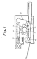
- Fig. 1 is a schematic side sectional view of the printer of the embodiment;
- Fig. 2 shows a side sectional view of the developing apparatus of one embodiment;
- Fig. 3 is a perspective view of the developing roller of the embodiment;
- Fig. 4 shows a distribution of the magnetic flux density of the developing roller of the embodiment;
- Fig. 5 is a partially enlarged view showing the distribution of the magnetic flux density of the developing roller of the embodiment;
- Fig. 6 is a graph showing a relationship between the position of the developer restriction member and the printing density;
- Fig. 7 is a graph showing a relative position of the developer restriction member with regard to the magnetic flux density distribution;
- Fig. 8 is a chart showing results of the image evaluation;
- Fig. 9 is an explanatory drawing showing the magnetization principle;
- Fig. 10 is a lateral view of the developing roller of another embodiment;
- Fig. 11 shows the relationship between the blade and the magnetic poles B and C;
- Fig. 12 shows a developing roller and the distribution of the magnetic flux density;
- Fig. 13 illustrate a method of forming a uniform magnetic flux density section by a balance control between the two magnetic poles B and C;
- Fig. 14 illustrates another method of forming uniform magnetic flux density section by providing a new magnetic pole C′;
- Fig. 15 shows a distribution of the magnetic flux density in the embodiment of Fig. 13;
- Fig. 16 shows a distribution of the magnetic flux density in the embodiment of Fig. 14;
- Fig. 17 is a partially enlarged view showing the state of the developer head;
- Fig. 18 is an explanatory drawing of the principle of the developing apparatus;
- Fig. 19 shows a distribution of the magnetic flux density of the developing roller of the conventional example; and
- Fig. 20 is a partially enlarged view of the magnetic flux density distribution of the developing roller of the conventional example.
- Embodiments of the present invention will now be described with reference to the drawings.
- Figure 1 shows an electrophotographic printer. The present invention is widely applicable to not only printers but also copying machines and the like.
- In Fig. 1,
reference numeral 3 denotes a photosensitive drum rotatable around a shaft thereof, 11 denotes a preelectrostatic charger for electrifying thephotosensitive drum photosensitive drum 3 by a scanned laser beam, to form an electrostatic latent image on the surface of thephotosensitive drum 3. - Also,
reference numeral 10 represents a magnetic brush developing apparatus for developing the electrostatic latent image formed on thephotosensitive drum 3, to form a toner image, 13 designates a transfer device for transferring the toner image onto a printing sheet, 14 designates a cleaner for removing residual toner on the surface of thephotosensitive drum - Figure 2 shows the developing
apparatus 10. - Contained within a
development container 7 is a twocomponent developer 4 composed of a toner 4a, a colored powder, and acarrier 4b, i.e., a magnetic powder. The toner 4a is supplied into thedevelopment container 7 from atoner hopper 21 provided on the upper portion through atoner supply roller 22. - The toner used in this embodiment is made of styrene acrylic series or polyester series resin and has an average particle diameter of 11 to 12 µm. The carrier, which is a resin-coated magnetic material such as magnetite or ferrite has an average particle diameter of about 100 µm. A saturation magnetization of the carrier is 80 emu/g.
-
Reference numeral 23 stands for a stirring device for stirring the developer within thedevelopment container 7, to produce an electrostatic charge therein. 24 signifies a flow restriction member for returning thedeveloper 4 held back by adeveloper restriction member 2, to the stirringdevice developer 4 through a measurement of a permeability of thedeveloper 4, to thereby determine the toner replenishment timing. - The
development container 7 has at its left end portion an opening which defines a developingsection 9 for developing the surface of thephotosensitive drum 3, in which there is provided a developingroller 1 constituted of acylindrical magnet 1b made of a magnetized magnetic material, and,a tubularrotational sleeve 1a rotatably driven and arranged so as to cover the surface of themagnet 1b. - In this embodiment, the
magnet 1b is made of ferrite and has a shaft made of a non-magnetic material such as aluminum alloy, for example. Also, therotational sleeve 1a is made of the non-magnetic material such as aluminum alloy, for example. - Figure 3 is a perspective view showing the partially cut-away developing
roller 1. Themagnet 1b shown in Fig. 3 includes a plurality of radially alternately magnetized lines (five lines). - The
developer 4 held on the surface of therotational sleeve 1a through a magnetic force exerted by themagnet 1b, is carried to the developingsection 9 by the rotation of therotational sleeve 1a. - As shown in Fig. 2, a developer restriction member or
blade 2 made of a non-magnetized material is rigidly fixed to thedevelopment container 7 so as to be parallel to the axial direction of therotational sleeve 1a. Provided between thedeveloper restriction member 2 and therotational sleeve 1a is a predetermined small gap (1.0 mm in this embodiment), and as a result, the height of the developer 4 (the height of the head) carried by the rotation of therotational sleeve 1a is restricted to a predetermined value by thedeveloper restriction member 2. - Then, only the toner which develops the electrostatic latent image formed on the surface of the
photosensitive drum 3 is transmitted to thephotosensitive drum 3, and the remainingdeveloper 4 is returned to thedevelopment container 7 by the developingroller 1. - Figure 4 shows a distribution of the magnetic flux density, in which
reference numeral 6 denotes a developer restriction member facing member arranged opposite to thedeveloper restriction member 2. - A magnetic pole A is an N pole confronting the
photosensitive drum 3. Magnetic poles B, C, and E are mainly utilized to carry thedeveloper 4, and a magnetic pole D is mainly used to apply thedeveloper 4 to the developingroller 1. Further, the magnetic poles E and D have the same polarity, and therebetween the developer is exfoliated by the developingroller 1. Further, the exfoliateddeveloper 4 is stirred by the stirringdevice 23 for re-use. - As shown in the enlarged view of Fig. 5, between the magnetic poles B and C the developer restriction
member facing section 6 has a substantially uniform magnetic flux density of, for example, 80 to 90 gauss, due to the magnetic pole C. - That magnetic flux density lying between 80 to 90 gauss is suitable to obtain a satisfactory image in the apparatus of this embodiment, the magnitude of which may be appropriately selected depending on the properties of the apparatus.
- The uniform magnetic flux density section Z is made to extend across 10 degrees or more and is 20 degrees in total at both sides of the developer restriction member facing the
position 6a therebetween. - Methods of forming the thus widely spread uniform magnetic flux density section Z will be described later in detail.
- As described earlier, the parts mounted in the apparatus have respective mounting precisions (errors permissible in the manufacture) and the like. Accordingly, when the mounting precision of the
developer restriction member 2 is ±0.5 degrees, the magnetized positional precision of themagnet 1b is ±3 degrees, the fixing precision of themagnet 1b is ±0.5 degrees, and the processing precision of the other parts is ±1 degree, the position of thedeveloper restriction member 2 relative to the magnetic flux density distribution of the developingroller 1 includes a precision shown by a positional precision range Q. - Q is on the order of 10 degrees (±5 degrees), and the uniform magnetic flux density section Z is formed so as to be substantially double the Q in this embodiment.
- As a result, the magnetic flux density of the developer restriction
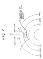
member facing section 6 is almost unchanged, and accordingly, even if a different developing apparatus is used, the amount ofdeveloper 4 supplied to the developingsection 9 is unchanged in each developing apparatus. - Figure 6 is a graph showing the relationship between the relative positional variation of the
developer restriction member 2 with respect to the magnetic flux density distribution of the developingroller 1, and the printing density (developing density). Figure 7 shows the + or - direction of the graph. The variation in the relative position of the developer restriction member with respect to the magnetic flux density distribution of the magnet, toward the directions as shown in the drawing, are designated by + and -, respectively. - A solid line in Fig. 6 shows the apparatus of this embodiment, and a broken line shows the conventional apparatus. As can be seen, this embodiment apparatus is subjected to very little change in the printing density regardless of the position of the
developer restriction member 2 within the positional precision range Q. - Therefore, each developing apparatus can present a similar uniform image quality within a predetermined range, with respect to the image density, fogging, skip, carrier adhesion and the like.
- Figure 8 shows the angle range for the uniform magnetic flux density section Z of the developing roller used in the developing apparatus, and the ratio of the developing apparatus by which a satisfactory printing can be obtained when the variation range of the magnetic flux density is changed. The image density of a 4 mm square solid of an output image was judged to be satisfactory at 1.2 or over.
- In the drawing, o means that the ratio (good ratio of the apparatus) of the developing apparatus at which a satisfactory printing can be obtained is approximately 100%, o means that the ratio (good ratio of the apparatus) of the developing apparatus at which a satisfactory printing can be obtained is 80% or more, Δ signifies that the ratio (good ratio of the apparatus) of the developing apparatus at which a satisfactory printing can be obtained is 60% or more, and x signifies that the ratio (good ratio of the apparatus) of the apparatus at which a satisfactory printing can be obtained is 50% or less. It will be appreciated from Fig. 8 that the developing apparatus using a developing roller having a uniform magnetic flux density section Z with a wider angle range, and having a narrower variation angle of the magnetic flux density within the foregoing angle range, is able to obtain a satisfactory printing with a 1.2 or more image density.
- For example, for the developing apparatus using a developing roller (as used in the embodiment in Fig. 6) having an angle range of ±10 degrees or more and having a variation range of the magnetic flux density of ±10 or less, the good ratio of the apparatus was almost 100%, which is ideal result.
- On the contrary, for the developing apparatus using a developing roller having an angle range of + 5 degrees or more, and the variation range of the magnetic flux density of ±15% or less, the good ratio of the apparatus was 80% or more, and for the developing apparatus using a developing roller having an angle range of ±3 degrees and the variation range of the magnetic flux density of ±20%, the good ratio of the apparatus was 60% or more.
- For the developing apparatus using a developing roller having an angle range of ±2 degree or less and the variation range of the magnetic flux density of ±25%, or more, the good ratio of the apparatus was 50% or less, which is unusable in practice.
- Also, in the case of the developing apparatus using a developing roller having an angle range of ±2 degrees or less, and the variation range of the magnetic flux density of + 10 or less, as well as the developing apparatus using a developing roller having an angle range of ±10 degrees or more and an variation range of the magnetic flux density of ±25% or more, the good ratio of the apparatus was not less than 60%.
- From the above experimental results, it is understood that the uniform magnetic flux density section Z should be formed to extend by 3 degrees, preferably by 5 degrees, more preferably 10 degrees in terms of angle range on both sides of the developer restriction
member facing section 6 therebetween, more preferably, a 5 degrees angle range or more, most preferably a 10 degrees angle range or more. - It is also understood that the vertical magnetic flux density of the uniform magnetic flux density section Z should lie within a range of ±20%, preferably ±15%, more preferably ±10% with respect to the preset value at the developer restriction
member facing section 6. - In these experiments, 16 kinds of developing rollers were used to measure 20 rollers each.
- A description is now given of a method of fabricating a developing roller lying within the angle range and the variation range of the magnetic flux density as described above.
- First, the magnetizing of the
magnet 1b will be described with reference to Fig. 9. - As shown in the drawing, an
electromagnet 30 is arranged surrounding a magnetraw material 1c. A coil (not shown) of theelectromagnet 30 is then energized to exert a magnetic force on theelectromagnet 30, to thereby magnetize the magnetraw material 1c to form amagnet 1b. In this case, the range of the angular position of each magnetic pole is determined by the angular positional arrangement of theelectromagnet 30, and the magnitude of the magnetic flux density of each magnetic pole is determined by the current supplied to the coil of theelectromagnet 30. - Figure 10 shows a developing roller of another embodiment in accordance with the present invention. In the drawing, the
magnet 1b has a shaft having planes to which magnets are attached, and through an appropriate magnetic flux density and the angle arrangement, a satisfactory distribution of the magnetic flux density can be obtained. - Methods of forming a uniform magnetic flux density section Z will now be described with reference to Figs. 11 to 16.
- Figure 11 shows the relationship between the positions of the developer restriction member or
blade 2 and the two magnetic poles B and C located on the circumference of the developingroller 1 and between these magnetic poles B and C. There are two methods of forming the uniform magnetic flux density section Z, one being attained by a balance control between the two magnetic poles B and C located between these magnetic poles B and C, and the other being attained by providing a new magnetic pole C′ in the vicinity of the developer restriction member (blade) 2. - In Fig. 12(a) shows a structure of the developing roller and Fig. 12(b) shows the vertical component of the magnetic flux density distribution on the
rotational sleeve 1a of the developingroller 1. As mentioned hereinbefore, the developingroller 1 comprises therotational sleeve 1a and themagnet 1b. An isotropic ferrite magnet is used as a material of themagnet 1b. As shown in Fig. 12(a), if an external magnetic field is exerted on such a magnet material, the magnetic poles (A, B, C, ...) are formed. Figure,12(b) shows the results of the measurements of the magnetic flux density distribution on therotational sleeve 1a. The positions of the magnetic poles B and C are shown at the bottom of the drawing. In Fig. 12(b), the abscissa indicates an angle ϑ. - A method of forming an uniform magnetic flux density section Z by a balance control between the two magnetic poles B and C, between which the developer restriction member or
blade 2 is arranged is now described. If the distance between the two magnetic poles B and C is increased, as shown in Fig. 13(a), not only does the magnetic flux flow from the magnetic pole C (N-pole) toward the magnetic pole B (S-pole), but also the magnetic flux flows toward the inner magnetic poles located at the side of a shaft of the developing roller, as shown by broken lines in Fig. 13(a), and thus, both magnetic fluxes are mutually balanced so that a flat portion is formed. If the strength of magnetization and the width of these two magnetic poles B and C are the same, the flat portion is located at a zero line of the magnetic flux density, but if the strength of magnetization of one of the magnetic poles B and C is smaller than that of the other, or if the width of one is narrower than that of the other, the flat portion is not located at the zero line. For example, if the width of the magnetic pole C (N-pole) is narrower, the amount of the magnetic flux around the magnetic pole B (S-pole) is increased, and therefore, the flat portion is moved to the side of N-pole, and thus a uniform magnetic flux density section Z is formed at the side of N-pole, as shown in Fig. 13(c). - Therefore, in a method of obtaining a balance control between the two magnetic poles B and C, a uniform magnetic flux density section (flat portion) Z can be advantageously formed if the angle ϑ₀ (Fig. 12(a)) between the center lines of the two magnetic poles B and C is not less than three times the average width of these magnetic poles B and C, and if the width of one of the magnetic poles B and C is smaller (not more than 80%) than that of the other, or the magnetic flux density of one is smaller than that of the other.
- A method of forming a uniform magnetic flux density section Z by providing a new magnetic pole C′ will now be described with reference to Fig. 14. As mentioned above (1), if the distance between the two magnetic poles B and C is increased, a change of the magnetic flux density will be lost and will not be flat, as shown in Fig. 14(a). Therefore, a new magnetic pole C′ is arranged between the two magnetic poles B and C and opposite the developer restriction member or
blade 2. The distance between the magnetic poles B and C′ is a little bit shorter than the distance between the magnetic poles C′ and C. The width of the magnetic pole C′ is about one half that of the magnetic pole B or C and the strength of magnetization of the magnetic pole C′ is about 5 to 50% that of the magnetic pole B or C. Figure 14(b) shows a distribution of magnetic flux density of this magnetic pole C′ on therotational sleeve 1a. The distribution of magnetic flux density between the magnetic poles B and C is represented as a combination of both, and thus a uniform magnetic flux density section Z is formed, as shown in Fig. 14(c). - Therefore, a uniform magnetic flux density section (flat portion) Z can be advantageously formed by providing a new magnetic pole C′, the width of which is about a half that of the magnetic pole B or C and a strength of magnetization thereof is about 5 to 50% of that of the magnetic pole B or C, at a position between the developer restriction member or
blade 2 and the two magnetic poles B and C. In this case, the angle ϑ, (Fig. 12(a)) between the center lines of the two magnetic poles B and C is not less than twice the average width of these magnetic poles B and C. - Figures 15 and 16 show a distribution of the magnetic flux density in the above-mentioned embodiments (1) and (2), respectively. In Fig. 15, the strength of magnetization of the magnetic poles A, B, C, D and E is the same, but the width thereof is changed as follows. Also the positions of these magnetic poles A, B, C, D and E are set as follows.

- In Fig. 16, the strength of magnetization and the width of the magnetic poles A, B, C, C′, D and E are set as follows. Also the positions of these magnetic poles are set as follows.

- It should be noted that the present invention is not confined to the above embodiments. With respect to the uniform magnetic flux density section Z, providing there exists an appropriate magnetic flux density (for example, 80 to 90 gauss) within the range of at least 5 degrees or more, and 10 degrees or more in total on the both sides of the designed developer restriction
member facing point 6a therebetween, the image quality among the apparatuses can be made largely uniform compared to the conventional apparatuses. - Also, the above angle may be made at least 3 degrees or more on both sides thereof, and 6 degrees or more in total, to obtain a better effect.
Claims (12)
- A magnetic brush developing apparatus, comprising:
a development container for containing a developer (4);
a magnet (1b) stationarily located in said development container (7) and having magnetic poles radially provided on a plurality of points thereof;
a rotational sleeve (1a) arranged so as to cover the outer circumference of said magnet (1b) and rotatably driven to carry the developer (4) of said development container (7); and
a developer restriction member (2) arranged opposite to said rotational sleeve (1a) to restrict the amount of the developer (4) carried by said rotational sleeve (1a);
wherein at the position (6a) facing said developer restriction member (2), and in its vicinity (6), there is formed a uniform magnetic flux density section (Z) having a magnetic flux density whose radial component is substantially uniform on the periphery of the said rotational sleeve (1a). - A magnetic brush developing apparatus according to claim 1, wherein said uniform magnetic flux density section (Z) includes a distribution of magnetic flux density whose vertical component is substantially uniform in a wider range than that of any of a magnetized positional precision for said magnet (1b), a mounting precision of said magnet (1b) to said development container (7), and a mounting precision of said developer restriction member (2) to said development container (7).
- A magnetic brush developing apparatus according to claim 1, wherein said uniform magnetic flux density section (Z) includes a distribution of magnetic flux density whose vertical component is substantially uniform in a wider range than that of a relative mounting positional precision between said uniform magnetic flux density section (Z) and said developer restriction member (2).
- A magnetic brush developing apparatus according to claim 1, wherein said uniform magnetic flux density sections (Z) are provided on both sides of said developer restriction member facing point (6a) therebetween so as to extend by an angle of at least 10 degrees each in terms of a rotational angle of said rotational sleeve (1a).
- A magnetic brush developing apparatus according to claim 1, wherein said uniform magnetic flux density section (Z) has a vertical magnetic flux density lying within the range of ±10% with respect to a preset value for said developer restriction member facing point (6a).
- A magnetic brush developing apparatus according to claim 1, wherein said uniform magnetic flux density section (Z) is provided on both sides of said developer restriction member facing point (6a) therebetween so as to extend by an angle of at least 3 degrees in terms of a rotation angle of said rotational sleeve (1a), and said uniform magnetic flux density sections (Z) has a vertical magnetic flux density lying within the range of ±20% with respect to a preset value for said developer restriction member facing point (6a).
- A magnetic brush developing apparatus according to claim 1, wherein said uniform magnetic flux density section (Z) is provided on both sides of said developer restriction member facing point (6a) therebetween so as to extend by an angle of at least 3 degrees in terms of a rotation angle of said rotational sleeve (1a), and said uniform magnetic flux density sections (Z) has a vertical magnetic flux density lying within the range of ±10% with respect to a preset value for said developer restriction member facing point (6a).
- A magnetic brush developing apparatus according to claim 1, wherein said uniform magnetic flux density section (Z) is provided on both sides of said developer restriction member facing point (6a) therebetween so as to extend by an angle of at least 10 degree in terms of a rotation angle of said rotational sleeve (1a), and said uniform magnetic flux density sections (Z) has a vertical magnetic flux density lying within the range of ±20% with respect to a preset value for said developer restriction member facing point (6a).
- A magnetic brush developing apparatus according to claim 1, wherein said uniform magnetic flux density section (Z) is provided on both sides of said developer restriction member facing point (6a) therebetween so as to extend by an angle of at least 5 degree in terms of a rotation angle of said rotational sleeve (1a), and said uniform magnetic flux density sections (Z) has a vertical magnetic flux density lying within the range of ±15% with respect to a preset value for said developer restriction member facing point (6a).
- A magnetic brush developing apparatus according to claim 1, wherein said developer restriction member (2) is arranged between two (B, C) of said plurality of magnetic poles, an angle (ϑ₀) between center lines of said two magnetic poles (B, C) is not less than three times an average width of said two magnetic poles (B, C), and a width of one of said two magnetic poles (B, C) is smaller than that of the other.
- A magnetic brush developing apparatus according to claim 1, wherein said developer restriction member (2) is arranged between two (B, C) of said plurality of magnetic poles, an angle (ϑ₀) between center lines of said two magnetic poles (B, C) is not less than three times an average width of said two magnetic poles (B, C), and a magnetic flux density of one is smaller than that of the other.
- A magnetic brush developing apparatus according to claim 1, wherein said developer restriction member (2) is arranged between two (B, C) of said plurality of magnetic poles, an angle (ϑ₀) between center lines of said two magnetic poles (B, C) is not less than twice an average width of said two magnetic poles (B, C), and a further magnetic pole (C′), whose width is about a half that of said magnetic pole (B or C) and having a strength of magnetization of about 5 to 50% of that of said magnetic pole (B or C), at a position between said two magnetic poles (B, C).
Priority Applications (1)
| Application Number | Priority Date | Filing Date | Title |
|---|---|---|---|
| EP95102168A EP0658826B1 (en) | 1990-09-03 | 1991-08-22 | A magnetic brush developing apparatus |
Applications Claiming Priority (2)
| Application Number | Priority Date | Filing Date | Title |
|---|---|---|---|
| JP23390690 | 1990-09-03 | ||
| JP233906/90 | 1990-09-03 |
Related Child Applications (1)
| Application Number | Title | Priority Date | Filing Date |
|---|---|---|---|
| EP95102168.2 Division-Into | 1995-02-16 |
Publications (3)
| Publication Number | Publication Date |
|---|---|
| EP0474409A2 true EP0474409A2 (en) | 1992-03-11 |
| EP0474409A3 EP0474409A3 (en) | 1992-08-26 |
| EP0474409B1 EP0474409B1 (en) | 1995-10-25 |
Family
ID=16962441
Family Applications (2)
| Application Number | Title | Priority Date | Filing Date |
|---|---|---|---|
| EP91307747A Expired - Lifetime EP0474409B1 (en) | 1990-09-03 | 1991-08-22 | A magnetic brush developing apparatus |
| EP95102168A Expired - Lifetime EP0658826B1 (en) | 1990-09-03 | 1991-08-22 | A magnetic brush developing apparatus |
Family Applications After (1)
| Application Number | Title | Priority Date | Filing Date |
|---|---|---|---|
| EP95102168A Expired - Lifetime EP0658826B1 (en) | 1990-09-03 | 1991-08-22 | A magnetic brush developing apparatus |
Country Status (3)
| Country | Link |
|---|---|
| EP (2) | EP0474409B1 (en) |
| KR (1) | KR950001827B1 (en) |
| DE (2) | DE69114089T2 (en) |
Citations (4)
| Publication number | Priority date | Publication date | Assignee | Title |
|---|---|---|---|---|
| DE3003692A1 (en) * | 1979-02-02 | 1980-08-14 | Canon Kk | DEVELOPMENT DEVICE |
| US4492456A (en) * | 1981-07-31 | 1985-01-08 | Knoishiroku Photo Industry Co. Ltd. | Device for developing electrostatic latent images |
| US4825241A (en) * | 1986-07-16 | 1989-04-25 | Minolta Camera Kabushiki Kaisha | Electrostatic latent image developing apparatus |
| US4851872A (en) * | 1986-05-15 | 1989-07-25 | Minolta Camera Kabushiki Kaisha | Developing device with developer sleeve facilitating developer supply adjustment by bristle height regulating member |
Family Cites Families (2)
| Publication number | Priority date | Publication date | Assignee | Title |
|---|---|---|---|---|
| US4800412A (en) * | 1985-03-22 | 1989-01-24 | Minolta Camera Kabushiki Kaisha | Apparatus for developing electrostatic latent images |
| JPH01154182A (en) * | 1987-12-11 | 1989-06-16 | Minolta Camera Co Ltd | Developing device |
-
1991
- 1991-08-22 DE DE69114089T patent/DE69114089T2/en not_active Expired - Lifetime
- 1991-08-22 EP EP91307747A patent/EP0474409B1/en not_active Expired - Lifetime
- 1991-08-22 DE DE69124120T patent/DE69124120T2/en not_active Expired - Lifetime
- 1991-08-22 EP EP95102168A patent/EP0658826B1/en not_active Expired - Lifetime
- 1991-09-03 KR KR1019910015308A patent/KR950001827B1/en not_active IP Right Cessation
Patent Citations (4)
| Publication number | Priority date | Publication date | Assignee | Title |
|---|---|---|---|---|
| DE3003692A1 (en) * | 1979-02-02 | 1980-08-14 | Canon Kk | DEVELOPMENT DEVICE |
| US4492456A (en) * | 1981-07-31 | 1985-01-08 | Knoishiroku Photo Industry Co. Ltd. | Device for developing electrostatic latent images |
| US4851872A (en) * | 1986-05-15 | 1989-07-25 | Minolta Camera Kabushiki Kaisha | Developing device with developer sleeve facilitating developer supply adjustment by bristle height regulating member |
| US4825241A (en) * | 1986-07-16 | 1989-04-25 | Minolta Camera Kabushiki Kaisha | Electrostatic latent image developing apparatus |
Also Published As
| Publication number | Publication date |
|---|---|
| DE69124120T2 (en) | 1997-04-17 |
| EP0474409A3 (en) | 1992-08-26 |
| DE69114089D1 (en) | 1995-11-30 |
| KR920007427A (en) | 1992-04-28 |
| EP0474409B1 (en) | 1995-10-25 |
| DE69114089T2 (en) | 1996-04-04 |
| EP0658826B1 (en) | 1997-01-08 |
| KR950001827B1 (en) | 1995-03-03 |
| DE69124120D1 (en) | 1997-02-20 |
| EP0658826A1 (en) | 1995-06-21 |
Similar Documents
| Publication | Publication Date | Title |
|---|---|---|
| US6978109B2 (en) | Image forming apparatus | |
| US6081684A (en) | Method and apparatus for image forming capable of performing an improved circulation of developer | |
| JPH03251882A (en) | Developing device | |
| US4660505A (en) | Developing apparatus | |
| JP2002251072A (en) | Developing roller, manufacturing method of the same, developing device and image forming device | |
| US5424489A (en) | Magnetic brush developing apparatus | |
| US5202730A (en) | Developing process using two-component type magnetic developer | |
| US5396026A (en) | Magnetic brush developing apparatus | |
| EP0474409B1 (en) | A magnetic brush developing apparatus | |
| US5484680A (en) | Magnetic brush developing method | |
| JP2725686B2 (en) | Magnetic brush developing device | |
| JP2822476B2 (en) | Developing device | |
| JP2005316503A (en) | Image forming method and image forming apparatus | |
| JPS648821B2 (en) | ||
| JPS60220374A (en) | Developing device | |
| JPH0644082Y2 (en) | Magnet roll | |
| JPS61200563A (en) | Developing device | |
| JPH0990758A (en) | Developing device | |
| JPH0418306B2 (en) | ||
| JPS60220376A (en) | Developing device | |
| JPH10123838A (en) | Developing roll | |
| JPH04240675A (en) | Developing device | |
| JPH01219778A (en) | Developing device | |
| JPS61270776A (en) | Magnetic brush developing device | |
| JPH01251065A (en) | Developing device |
Legal Events
| Date | Code | Title | Description |
|---|---|---|---|
| PUAI | Public reference made under article 153(3) epc to a published international application that has entered the european phase |
Free format text: ORIGINAL CODE: 0009012 |
|
| AK | Designated contracting states |
Kind code of ref document: A2 Designated state(s): DE GB IT |
|
| PUAL | Search report despatched |
Free format text: ORIGINAL CODE: 0009013 |
|
| AK | Designated contracting states |
Kind code of ref document: A3 Designated state(s): DE GB IT |
|
| 17P | Request for examination filed |
Effective date: 19921016 |
|
| 17Q | First examination report despatched |
Effective date: 19940407 |
|
| GRAA | (expected) grant |
Free format text: ORIGINAL CODE: 0009210 |
|
| AK | Designated contracting states |
Kind code of ref document: B1 Designated state(s): DE GB IT |
|
| PG25 | Lapsed in a contracting state [announced via postgrant information from national office to epo] |
Ref country code: IT Free format text: LAPSE BECAUSE OF FAILURE TO SUBMIT A TRANSLATION OF THE DESCRIPTION OR TO PAY THE FEE WITHIN THE PRE;WARNING: LAPSES OF ITALIAN PATENTS WITH EFFECTIVE DATE BEFORE 2007 MAY HAVE OCCURRED AT ANY TIME BEFORE 2007. THE CORRECT EFFECTIVE DATE MAY BE DIFFERENT FROM THE ONE RECORDED.SCRIBED TIME-LIMIT Effective date: 19951025 |
|
| XX | Miscellaneous (additional remarks) |
Free format text: TEILANMELDUNG 95102168.2 EINGEREICHT AM 22/08/91. |
|
| REF | Corresponds to: |
Ref document number: 69114089 Country of ref document: DE Date of ref document: 19951130 |
|
| PLBE | No opposition filed within time limit |
Free format text: ORIGINAL CODE: 0009261 |
|
| STAA | Information on the status of an ep patent application or granted ep patent |
Free format text: STATUS: NO OPPOSITION FILED WITHIN TIME LIMIT |
|
| 26N | No opposition filed | ||
| REG | Reference to a national code |
Ref country code: GB Ref legal event code: IF02 |
|
| REG | Reference to a national code |
Ref country code: GB Ref legal event code: 732E |
|
| PGFP | Annual fee paid to national office [announced via postgrant information from national office to epo] |
Ref country code: DE Payment date: 20100728 Year of fee payment: 20 |
|
| PGFP | Annual fee paid to national office [announced via postgrant information from national office to epo] |
Ref country code: GB Payment date: 20100818 Year of fee payment: 20 |
|
| REG | Reference to a national code |
Ref country code: DE Ref legal event code: R071 Ref document number: 69114089 Country of ref document: DE |
|
| REG | Reference to a national code |
Ref country code: DE Ref legal event code: R071 Ref document number: 69114089 Country of ref document: DE |
|
| PG25 | Lapsed in a contracting state [announced via postgrant information from national office to epo] |
Ref country code: GB Free format text: LAPSE BECAUSE OF EXPIRATION OF PROTECTION Effective date: 20110821 |
|
| PG25 | Lapsed in a contracting state [announced via postgrant information from national office to epo] |
Ref country code: DE Free format text: LAPSE BECAUSE OF EXPIRATION OF PROTECTION Effective date: 20110823 |