EP0474373A2 - Method and apparatus for verifying the configuration of a link connected network - Google Patents
Method and apparatus for verifying the configuration of a link connected network Download PDFInfo
- Publication number
- EP0474373A2 EP0474373A2 EP91307332A EP91307332A EP0474373A2 EP 0474373 A2 EP0474373 A2 EP 0474373A2 EP 91307332 A EP91307332 A EP 91307332A EP 91307332 A EP91307332 A EP 91307332A EP 0474373 A2 EP0474373 A2 EP 0474373A2
- Authority
- EP
- European Patent Office
- Prior art keywords
- link
- configuration
- adapter
- physical
- units
- Prior art date
- Legal status (The legal status is an assumption and is not a legal conclusion. Google has not performed a legal analysis and makes no representation as to the accuracy of the status listed.)
- Withdrawn
Links
Images


Classifications
-
- H—ELECTRICITY
- H04—ELECTRIC COMMUNICATION TECHNIQUE
- H04L—TRANSMISSION OF DIGITAL INFORMATION, e.g. TELEGRAPHIC COMMUNICATION
- H04L69/00—Network arrangements, protocols or services independent of the application payload and not provided for in the other groups of this subclass
Definitions
- the present invention relates to a method of and apparatus for verifying and correcting the definition of the configuration of a link-connected network, especially an input/output (I/O) network in which host processors are coupled to peripheral device control units via switches and duplex serial fiber optic links.
- I/O input/output
- I/O systems for interconnecting processors and control units via serial fiber optic links have been previously described in the copending applications of P. J. Brown et al., Serial No. 07/429,267, filed October 30, 1989, of C. J. Bailey et al., Serial No. 07/444,190, filed November 28, 1989, and of A. Carusone et al., Serial No. 07/516,387, filed April 30, 1990, all of which are assigned to the owner of this application.
- one or more crosspoint switches having serial fiber optic ports may be actuated to form either a static or a dynamic connection between pairs of ports to establish bidirectional communication between a processor and a control unit coupled to one or more peripheral devices such as a terminal, a printer, a direct access storage device (DASD) (e.g., a magnetic or optical disk drive), or a magnetic tape drive.
- DASD direct access storage device
- a first link may interconnect a processor and a switch, while a second link may interconnect the switch and a control unit to complete the connection between the processor and the control unit.
- Each link may be several kilometers in length.
- Planning and implementing the I/O configuration of a system such as the one described above can be a difficult and challenging task for the user.
- each activity can be extremely complex. For example, in defining the logical I/O configuration the user must account for competing requirements and constraints when designing a plan for I/O accessibility.
- apparatus for verifying the configuration of a network of units interconnected by links, each link coupling a pair of units via respective link adapters associated with the units, each of the link adapters having a unique identifier associated therewith, the apparatus comprising: means for generating a logical configuration map indicating an assumed configuration of the network; means associated with each of the links for transmitting the identifier associated with the link adapter at one end of the link over the link to the link adapter at the other end of the link to generate an associated pair of link adapter identifiers identifying the link; means for generating from the associated pairs of link adapter identifiers a physical configuration map indicating the actual configuration of the network; and means for comparing the logical configuration map with the physical configuration map to determine the existence of any discrepancies therebetween.
- a method of verifying the configuration of a network of units interconnected by links each link coupling a pair of units via respective link adapters associated with the units, each of the link adapters having a unique identifier associated therewith, the method including: (a) generating a logical configuration map indicating an assumed configuration of the network; (b) for each of the links, transmitting the identifier associated with the link adapter at one end of the link over the link to the link adapter at the other end of the link to generate an associated pair of link adapter identifiers identifying the link; (c) generating from the associated pairs of link adapter identifiers a physical configuration map indicating the actual configuration of the network; and (d) comparing the logical configuration map with the physical configuration map to determine the existence of any discrepancies therebetween.
- a method and apparatus for verifying and correcting the configuration of a system in which processors are coupled to one another or to device control units either directly or through an intermediate unit such as a dynamic switch by way of links attached to link adapters of respective end units.
- Each pair of unit link adapters coupled to the respective ends of a link exchanges information identifying the unit and the adapter on that unit to generate pairs of associated link adapter identifiers identifying respective links.
- a physical configuration map indicating the actual physical system configuration is constructed from such "nearest neighbor" information.
- the physical configuration map is compared with a logical configuration map indicating the user-defined logical system configuration to determine the existence of any discrepancies therebetween.
- a program may take one of several corrective recovery actions, depending on the purpose and function of the program.
- the term "program” as used herein includes a software program as well as a hardware apparatus, also referred to as a "machine”.
- These recovery actions may include reports to the customer, requests for additional information, or other program-specific actions.
- the physical view of the configuration may hold a higher precedence than the logical definition, since I/O operations can only be performed on physical paths.
- a program or machine may therefore elect to consider the configuration described by the physical information to be a more accurate representation of the configuration, and therefore, for the purposes of the program, may conform the logical view to the physical view.
- Fig. 1 is a schematic diagram of a system of serially interconnected units in which the present invention may be used.
- Fig. 2 is an illustration of the general format of the link adapter identifiers used in the system shown in Fig. 1.
- Fig. 3 is an example of a configuration map of the system shown in Fig. 1, using link adapter identifiers of the type shown in Fig. 2.
- Fig. 4 is a flowchart illustrating the general sequence of steps followed to verify the configuration of the system shown in Fig. 1.
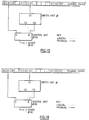
- Fig. 5 shows an example of an exchange of physical identifiers between I/O units.
- Fig. 6 is an example of a logscal I/O configuration map for a host processor.
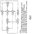
- Fig. 7 is an example of the physical I/O configuration map for the host processor shown in Fig. 6.
- Fig. 8 shows an example of an I/O configuration definition error.
- Fig. 9 is a table representing the physical configuration relationships of the system shown in Fig. 8.
- Fig. 10 is an example of the correction of the configuration error shown in Fig. 8 using physical identifiers.
- Fig. 11 is another example of an I/O configuration definition error.
- Fig. 12 is an example of the correction of the I/O configuration definition error shown in Fig. 11.
- Fig. 13 is yet another example of an I/O configuration definition error.
- Fig. 14 is an example of a correction of the I/O configuration definition error shown in Fig. 13.
- Fig. 15 is an example of an I/O configuration error involving the control unit-to-switch interface.
- Fig. 16 is an example of a correction of the I/O configuration error shown in Fig. 15.
- Fig. 17 depicts a data structure that may be used for the logical and physical configuration maps of the invention.
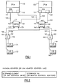
- a system in which the present invention may be used may include one or more processors 110 and 120 coupled to dynamic crosspoint switches 130 and 140 by serial fiber optic links 101, 102, 103 and 104.
- Each processor 110 or 120 comprises a central processing complex (CPC), with one or more central processing units (CPUs) (not separately shown), and a channel subsystem (CSS) for handling communications between the central processing complex and the other units of the system.
- CPC central processing complex
- CPUs central processing units
- CCS channel subsystem
- Each processor 110 or 120 has one or more host operating systems (“hosts" hereinafter) running thereon.
- hosts host operating systems
- the channel subsystem of processor 110 has a pair of link adapters 111 and 112 coupled to respective links 101 and 102, while similarly the channel subsystem of processor 120 has a pair of -link adapters 121 and 122 coupled to respective links 103 and 104.
- Link adapters 111, 112, 121 and 122 correspond to respective I/O channels, or channel paths, of the channel subsystems of processors 110 and 120 that are identified by channel path identifiers (CHPIDs).
- CHPIDs channel path identifiers
- Link 101 couples link adapter 111 of processor 110 to a link adapter 131 of switch 130; link 102 couples link adapter 112 of processor 110 to a link adapter 141 of switch 140; link 103 couples link adapter 121 of processor 120 to a link adapter 132 of switch 130; and link 104 couples link adapter 122 of processor 120 to a link adapter 142 of switch 140.
- Switch link adapters 131, 132, 141, and 142 correspond to respective ports or interfaces of switches 130 and 140, just as the link adapters of processors 110 and 120 correspond to respective channels (CHPIDs) of the processor channel subsystems.
- Each of links 101 to 104 is a duplex link containing a pair of fiber optic conductors for simultaneous bidirectional communication between the respective unit interfaces (channel and switch port) at the ends of the link.
- Switches 130 and 140 are in turn coupled to control units 150 and 160 associated with peripheral devices 171-172 181-182, such as the storage devices referred to above, by duplex serial fiber optic links 105, 106, 107 and 108.
- link 105 couples a link adapter 133 of switch 130 to a link adapter 151 of control unit 150
- link 106 couples a link adapter 143 of switch 140 to a link adapter 152 of control unit 150
- link 107 couples a link adapter 134 of switch 130 to a link adapter 161 of control unit 160
- link 108 couples a link adapter 144 of switch 140 to a link adapter 162 of control unit 160.
- Link adapters 151, 152, 161 and 162 correspond to respective interfaces of control units 150 and 160, in a manner similar to that of the link adapters of processors 110 and 120 and switches 130 and 140.
- each of switches 130 and 140 is shown as having only four ports, they may typically have many more for attachment to other units.
- each of switches 130 and 140 has 2n ports and may be actuated make up to n duplex connections between respective pairs of ports.
- n is 32
- switch 130 or 140 may be actuated to make up to 32 connections between respective pairs of ports, for a total of 64 pairwise connected ports.
- Switches 130 and 140 are capable of two basic types of connections: static and dynamic. Static connections are established between pairs of switch ports without regard to a particular message that may be passing between the ports; the ports remain connected, even though the connecting links may be inactive. A dynamic connection, on the other hand, is made for a particular communication between ports, and is broken when the communication is terminated. Although the particular protocol for making dynamic connections between switch ports does not as such form part of this invention, a preferred protocol is described in the copending application of P. J. Brown et al. referred to above, the specification of which is incorporated herein by reference.
- each of the link adapters of processors 110 and 120, switches 130 and 140, and control units 150 and 160 has a unique two-part link adapter identifier (LAID), or physical identifier, UNITID_ADAPTERID associated therewith.
- Fig. 2 shows the general format of the link adapter identifier.
- the first part of the identifier (UNITID) uniquely identifies the unit, distinguishing it from other types of units as well as from other units of the same type.
- the second part of the identifier identifies the particular link adapter as distinguished from other link adapters on the same unit.
- the reference numbers used to identify the link adapters also serve as possible link adapter identifiers (LAIDs).
- LAIDs link adapter identifiers
- the LAID for link adapter 111 on processor 110 could comprise the two-part identifier 110/111, the first part of which consists of a character string identifying the processor 110 and the second part of which consists of a tag identifying the particular channel (CHPID) to which the link adapter corresponds.
- the LAID for link adapter 131 of switch 130 could comprise a two-part identifier 130/131, the first part of which identifies the switch 130 and the second part of which identifies the particular port on switch 130 to which the link adapter corresponds.
- the control unit LAIDs could also be derived in an analogous manner.
- each link adapter Upon system startup or at some other appropriate time such as reinitialization, each link adapter transmits its LAID over the link to the link adapter at the other end of the link.
- link adapter 111 transmits its LAID 110/111 over the link to the link adapter 131 at the other end of the link, while link adapter 131 conversely transmits its LAID 130/131 over the same link to link adapter 111.
- Each link adapter associates one of the pair with with its own LAID and the other of the pair with the "neighboring" LAID.
- the neighboring or attached LAID has the same general format as the adapter's own determined LAID (Fig. 3).
- the fact the the identifiers are exchanged over the link being identified assures that the LAID pairs thus generated reflect the actual physical configuration of the system.
- a similar two-way exchange of identifiers occurs over each of the other links 102 to 108 of the system.
- a two-way exchange of identifiers is made for redundancy and to aid in fault isolation.
- each I/O unit in the configuration can build a data structure such as a table (Fig. 3) which contains entries of pairs of LAIDs for the links to which the I/O unit is physically attached.
- Fig. 4 shows the general sequence of steps for configuration verification which are performed by a program running on a host associated with one of processors 110 and 120 of the system shown in Fig. 1.
- the program obtains logical I/O configuration data from its channel subsystem (CSS) and attached I/O units (step 401).
- This information represents the user-inputted I/O configuration, which logically defines the channels, switch units, control units and devices of the system, as well as the path relationships between these I/O units.
- This logical I/O configuration data is used to generate a logical configuration map (step 402), which may have the same data structure as the physical configuration map to be described.
- the program then obtains physical I/O configuration data for its channels (CHPIDs), using channel subsystem (CSS) services; and the switches and control units to which it attached, using I/O device services (step 403).
- CHPIDs channels
- CSS channel subsystem
- I/O device services I/O device services
- This physical configuration data consists of the pairs of associated link adapter identifiers described above. These generated pairs of associated LAIDs identifying the physically connected links 101 to 108, which are collected by the processor, are used to generate a physical configuration map indicating the actual configuration of the system shown in Fig. 1 (step 404).
- the physical configuration map (as well as the logical configuration map referred to above) may be in the form of a table (Fig. 3), each entry of which contains a pair of associated LAIDs identifying a particular link.
- the table may contain double entries LAID1 LAID2 and LAID2 LAID1 for each link, since these paired entries would be generated automatically by the respective adapters at the end of each link by virtue of the two-way exchange of identifiers described above.
- Other data structures could also be used, as is apparent to those skilled in the art.
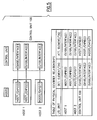
- Fig. 17 depicts a data structure that may be used for the logical and physical maps of the invention.
- the data structure is shown in an entity attribute relationship model. In the figure, the path referred to extends between a channel (CHPID) and an I/O device.
- CHPID channel
- the physical configuration map thus generated is compared (step 405) with the logical configuration map, which indicates the assumed configuration of the system previously created by the user, to determine the existence of any discrepancies therebetween in their description of link attachments between I/O units (step 410).
- the program associates the physical identifiers (i.e. the LAIDs) with it that describe the interface and what it is attached to (its "neighbor”). By correlating these two configuration maps, differences between the logical and physical views can be detected.
- the processor may (a) report to the user the detection of the mismatch, citing a probable cause if possible (step 411); (b) correct the logical view to match the physical mapping when errors are clearly determined (step 430); (c) augment the logical view to include the physical mapping when errors are detected, but resolution cannot be achieved (440); or (d) request additional user-inputted information (450).
- the user may conform the logical configuration map to the physical configuration to correct what is determined to be an erroneous view of the system.
- the discrepancies may indicate problems in the actual physical configuration, which must be addressed.
- FIG. 5 to 16 Further examples of the practice of the invention are shown in Figs. 5 to 16. Although link adapters shown in Fig. 1 are not expressly identified in the figures, they are to be understood as being present at the various interfaces depicted by the CHPIDs, ports and the like.
- Fig 5. is an example of an exchange of physical identifiers (LAIDs) between I/O units.
- This figure shows hosts 1 and 2 with channel paths (CHPIDs) 22, 23 and 77 attached to a control unit (CU) 100 with three attachable unit interfaces.
- CHPIDs channel paths
- CU control unit
- the physical identifiers are exchanged.
- the identifiers uniquely describe the I/O unit, and define the specific attachable unit interface.
- a program can obtain the physical identifiers (its interface, and its "neighbor") from every interface of the I/O unit.
- the physical configuration can be mapped from the information obtained from the I/O units.
- the physical map for any individual host may reflect other hosts' I/O resources because physical identifier information crosses host boundaries. In this way, the physical map can describe a set of I/O resources greater than that defined in the logical I/O configuration.
- the physical identifiers are provided as an example only.
- I/O units may have multiple interfaces, these units may be interconnected to more than one I/O unit, and in fact may be attached to multiple hosts. This means that physical identifiers can be obtained for the set of I/O units which is greater than that defined in the user-inputted I/O configuration for a specified host. The resulting physical map may thus include more I/O inits than is specified in the logical I/O configuration map. Conversely, the logical I/O configuration may reflect I/O units which are not represented in the physical configuration map. In this case, the I/O units are logically defined, but are not available (not installed or not powered on) and the physical identifiers cannot be obtained.
- the differences between the physical and logical maps may not represent I/O configuration errors, but can reveal pertinent information to the user regarding the I/O configuration. Therefore, a program may be designed to report this information to the user, and provide both the logical and physical I/O configuration mappings.
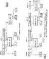
- Fig. 6 is an example of a logical I/O configuration map for host 1.
- This figure shows the logical I/O configuration map for host 1 based on the user-defined I/O configuration.
- Information on eight channel paths (CHPIDs), two switching units, five generalized I/O control units, and the I/O paths between them are described.
- Information on the configuration is obtained using channel subsystem (CSS) services. Note that because the I/O configuration is a logical definition, there is no assurance that the I/O units exist or are operable.
- CHPIDs channel paths
- SCS channel subsystem
- Fig. 7 is an example of a physical I/O configuration map for host 1.
- This figure shows the physical I/O configuration map for host 1 based on the configuration described by the logically defined configuration in Fig. 6.
- Two valuable classes of configuration information are revealed in the physical map: (1) I/O units which are logically defined to the host bit are not available; and (2) I/O units which are not logically defined to the host, but are physically attached to I/O units which are.
- Logically defined, not physically identified units include CHPID 11 and CU 3. No physical identifiers could be obtained for these I/O units, implying that the unit is not installed or not operational.
- Physically identified, not logically defined units include: host 2 CHPIDs 08, 68; host 3 CHPID 77; CU 4; and switch unit 3. The detection of these units is facilitated by the exchange of the physical identifiers. These identifiers are obtained by host 1 when it performs device I/O functions to the I/O nits which are defined to it. Since all physically attached information is returned, regardless of the logical definition, I/O units not defined to the host are revealed. From this information, the physical map is constructed.
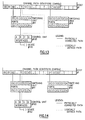
- Fig. 8 is an example of an I/O configuration definition error.
- This figure shows a channel path identifier (CHPID) 11 that was defined to be attached to switch 02, when it is actually attached to switch 01.
- the control units e.g., control unit 100
- the control units with paths to CHPID 11 are, as a consequence, associated with the ports on the incorrect switch.
- I/O operations can be successfully performed.
- the logical view is inconsistent with the physical state of the connectivity. For a configuration manager, this mismatch exposes the possible loss of critical resources when performing configuration change operations, such as reconfiguring the switches. That is, it appears that to change access from CHPID 11, switch 02 must be changed, but any action to switch 02 will be ineffective. Also, changes to switch 01 may accidentally cut off crucial I/O through CHPID 11.
- Fig. 9 is a table representing the physical configuration relationships of the system illustrated in Fig. 8. Note that on switch 02, the interfaces C2 and F2 have no "neighboring" physical identifiers associated with them. Conversely, on switch 01, the interfaces C2 and F2 do have "neighboring" physical identifiers associated with them. These relationships indicate the mismatch of the logical and physical configurations, and provide a means of correcting the error.
- Fig. 10 is an example of the correction of the configuration error shown in Fig. 8 using the physical identifiers shown in Fig. 9.
- the physical identifiers indicate that CHPID 11 is connected to port C2 on switching unit 01, and is not attached to switching unit 02.
- This condition represents an I/O configuration definition error.
- CHPID 02, CHPID 11 and CHPID 22 are defined to access control unit 100 on port F2.
- CHPID 02 and CHPID 11 will be able to access the control unit, while CHPID 22 will not.
- the program's logical view of the configuration is dynamically altered to match the physical mapping. For the configuration manager, this correction can ensure configuration changes without the accidental loss of critical resource.
- Fig. 11 is another example of an I/O configuration definition error.
- This figure shows a channel path identifier (CHPID) 11 that was defined to be attached to switch 01, when it is actually directly attached to control unit 100.
- CHPID channel path identifier
- the control unit that is defined to be accessed by CHPID 11 is actually attached to CHPID 11, so it is the logical definition, not the physical connection, that is in error.
- the control unit 100 with a path to CHPID 11 is, as a consequence of the error, associated with port F2 on switch 01. From the point of view of the physical path, I/O operations can be successfully performed. However, the logical view is inconsistent with the physical state of the connectivity. This mismatch is only a definition error, which may cause confusion to a user, but not an accidental critical loss of resource.
- Fig. 12 is an example of the correction of the I/O configuration definition error shown in Fig. 11.
- This figure shows a channel path identifier (CHPID) 11 that was defined to be attached to switch 01, when it is actually directly attached to control unit 100, after the correction to remove the association from the switch.
- CHPID channel path identifier
- the control unit 100 with a path to CHPID 11 is, as a consequence of the correction, no longer associated with a port on switch 01.
- Fig. 13 is yet another example of an I/O configuration definition error.
- This figure shows a channel path identifier (CHPID) 11 that was defined to be directly attached to control unit 100 (i.e., not be attached to a switch), when it is actually attached to switch 01.
- CHPID channel path identifier
- the control unit 100 that is defined to be accessed by CHPID 11 is actually attached to switch 01, so it is the logical definition, not the physical connection, that is in error.
- the control unit 100 with a path to CHPID 11 is, as a consequence of the configuration definition error, not associated logically with a port on switch 01. From the point of view of the physical path, I/O operations can be successfully performed. However, the logical view is inconsistent with the physical state of the connectivity.
- this mismatch exposes the possible loss of critical resources when performing configuration change operations, such as reconfiguring the switches. That is, changes to switch 01 may accidentally cut off crucial I/O through CHPID 11, since the CHPID is logically defined not to he on that switch.
- Fig. 14 is an example of the correction of the I/O configuration definition error shown in Fig. 13.
- This figure shows a channel path identifier (CHPID) 11 that was defined to be directly attached to a control unit (i.e., not be attached to a switch), when it is actually attached to switch 01 after the logical definition is corrected to match the physically determined configuration.
- CHPID channel path identifier
- the control unit with a path to CHPID 11 is, as a consequence, now associated with the ports on a switch.
- Fig. 15 is an example of an I/O configuration involving the control unit-to-switch interface.
- This figure shows control unit 100, interface B to be logically associated to interface E2 on switch 1, but is physically attached to interface F2. This can occur if there is an error in the I/O configuration definition, or if the I/O units were cabled incorrectly.
- the path through interface E2 to device 101 cannot become operational because there is no physical I/O unit attached to the interface. If a similar type control unit were attached to interface E2, a potential exists for I/O to be performed to the wrong device in error.
- CU 100 has a second path directly from CHPID 1 to interface A.
- Fig. 16 is an example of the correction of the I/O configuration error involving the control unit-to-switch interface shown in Fig. 15.
- the logical association of control unit 100 interface B has been altered to reflect the physical attachment to switch 1, interface F2. This determination is made possible by the detection of a mismatch between the logical I/O and physical configuration maps. Physical identifiers associated with control unit 100 are obtained by invoking device I/O services, using the path from CHPID 01 to the control unit interface A. Although the logical and physical maps are now in agreement, I/O will not be enabled through interface B; this will require either a I/O configuration definition change, or a cabling modification. However, as a result of the detection of the configuration mismatch, a program or machine can identify the specific problem, notifying the user of the probable cause.
Abstract
A method of and apparatus for creating a data structure or map describing the I/O configuration and of verifying and resolving errors in configuration data in a system in which processors (110,120) are coupled to one another or to device control units (150,160) either directly or through a dynamic switch (130,140) by way of links (105,107) attached to link adapters (151,153) of respective end units (130,150). Each pair of unit link adapters (151,133) coupled to the respective ends of a link (105) exchanges information identifying the unit (150) and the adapter on that unit (151). A physical configuration map indicating the actual physical system configuration is constructed from such "nearest neighbour" information. This physical configuration map is compared with a logical configuration map indicating the user-defined logical system configuration to determine the existence of any discrepancies therebetween, and one map is conformed to the other as appropriate.
Description
- The present invention relates to a method of and apparatus for verifying and correcting the definition of the configuration of a link-connected network, especially an input/output (I/O) network in which host processors are coupled to peripheral device control units via switches and duplex serial fiber optic links.
- Input/output (I/O) systems for interconnecting processors and control units via serial fiber optic links have been previously described in the copending applications of P. J. Brown et al., Serial No. 07/429,267, filed October 30, 1989, of C. J. Bailey et al., Serial No. 07/444,190, filed November 28, 1989, and of A. Carusone et al., Serial No. 07/516,387, filed April 30, 1990, all of which are assigned to the owner of this application. In the system described in these applications, one or more crosspoint switches having serial fiber optic ports may be actuated to form either a static or a dynamic connection between pairs of ports to establish bidirectional communication between a processor and a control unit coupled to one or more peripheral devices such as a terminal, a printer, a direct access storage device (DASD) (e.g., a magnetic or optical disk drive), or a magnetic tape drive. In a typical installation, a first link may interconnect a processor and a switch, while a second link may interconnect the switch and a control unit to complete the connection between the processor and the control unit. Each link may be several kilometers in length.
- Planning and implementing the I/O configuration of a system such as the one described above can be a difficult and challenging task for the user. There are two basic steps in enabling an I/O configuration: (1) the construction of a logical definition of the computing complex; and (2) the physical installation of I/O units and the cabling that interconnects these devices. Individually, each activity can be extremely complex. For example, in defining the logical I/O configuration the user must account for competing requirements and constraints when designing a plan for I/O accessibility.
- Accuracy and consistency between the logical and physical I/O configuration is central to the ability to perform the full range of I/O operations, configuration management, and connectivity management which is required within the computer complex. Because of the complexity, the logical and physical I/O configurations may not match accurately. Mismatches between the two may indicate errors in the I/O configuration definition, mistakes made when the I/O units were cabled, or uninstalled or not operational I/O units. Where the mismatches result in gross errors, I/O operations may fail outright. Sometimes, these mismatches may not result in the inability to perform I/O operations and errors, but subtle problems, such as access to the incorrect I/O units, may not be detected. In other cases, I/O may be performed completely correctly, but the logical-to-physical differences can result in a degradation of configuration or connectivity management services.
- In accordance with the present invention, there is now provided apparatus for verifying the configuration of a network of units interconnected by links, each link coupling a pair of units via respective link adapters associated with the units, each of the link adapters having a unique identifier associated therewith, the apparatus comprising: means for generating a logical configuration map indicating an assumed configuration of the network; means associated with each of the links for transmitting the identifier associated with the link adapter at one end of the link over the link to the link adapter at the other end of the link to generate an associated pair of link adapter identifiers identifying the link; means for generating from the associated pairs of link adapter identifiers a physical configuration map indicating the actual configuration of the network; and means for comparing the logical configuration map with the physical configuration map to determine the existence of any discrepancies therebetween.
- Viewing the present invention from a second aspect, there is now provided a method of verifying the configuration of a network of units interconnected by links, each link coupling a pair of units via respective link adapters associated with the units, each of the link adapters having a unique identifier associated therewith, the method including: (a) generating a logical configuration map indicating an assumed configuration of the network; (b) for each of the links, transmitting the identifier associated with the link adapter at one end of the link over the link to the link adapter at the other end of the link to generate an associated pair of link adapter identifiers identifying the link; (c) generating from the associated pairs of link adapter identifiers a physical configuration map indicating the actual configuration of the network; and (d) comparing the logical configuration map with the physical configuration map to determine the existence of any discrepancies therebetween.
- In a preferred embodiment of the present invention to be described shortly, there is provided a method and apparatus for verifying and correcting the configuration of a system in which processors are coupled to one another or to device control units either directly or through an intermediate unit such as a dynamic switch by way of links attached to link adapters of respective end units. Each pair of unit link adapters coupled to the respective ends of a link exchanges information identifying the unit and the adapter on that unit to generate pairs of associated link adapter identifiers identifying respective links. A physical configuration map indicating the actual physical system configuration is constructed from such "nearest neighbor" information. The physical configuration map is compared with a logical configuration map indicating the user-defined logical system configuration to determine the existence of any discrepancies therebetween.
- Upon the discovery of a logical-to-physical mismatch, a program may take one of several corrective recovery actions, depending on the purpose and function of the program. (The term "program" as used herein includes a software program as well as a hardware apparatus, also referred to as a "machine".) These recovery actions may include reports to the customer, requests for additional information, or other program-specific actions. For a configuration manager, the physical view of the configuration may hold a higher precedence than the logical definition, since I/O operations can only be performed on physical paths. A program or machine may therefore elect to consider the configuration described by the physical information to be a more accurate representation of the configuration, and therefore, for the purposes of the program, may conform the logical view to the physical view.
- A preferred embodiment of the present invention will now be described with reference to the accompanying drawings in which:
- Fig. 1 is a schematic diagram of a system of serially interconnected units in which the present invention may be used.
- Fig. 2 is an illustration of the general format of the link adapter identifiers used in the system shown in Fig. 1.
- Fig. 3 is an example of a configuration map of the system shown in Fig. 1, using link adapter identifiers of the type shown in Fig. 2.
- Fig. 4 is a flowchart illustrating the general sequence of steps followed to verify the configuration of the system shown in Fig. 1.
- Fig. 5 shows an example of an exchange of physical identifiers between I/O units.
- Fig. 6 is an example of a logscal I/O configuration map for a host processor.
- Fig. 7 is an example of the physical I/O configuration map for the host processor shown in Fig. 6.
- Fig. 8 shows an example of an I/O configuration definition error.
- Fig. 9 is a table representing the physical configuration relationships of the system shown in Fig. 8.
- Fig. 10 is an example of the correction of the configuration error shown in Fig. 8 using physical identifiers.
- Fig. 11 is another example of an I/O configuration definition error.
- Fig. 12 is an example of the correction of the I/O configuration definition error shown in Fig. 11.
- Fig. 13 is yet another example of an I/O configuration definition error.
- Fig. 14 is an example of a correction of the I/O configuration definition error shown in Fig. 13.
- Fig. 15 is an example of an I/O configuration error involving the control unit-to-switch interface.
- Fig. 16 is an example of a correction of the I/O configuration error shown in Fig. 15.
- Fig. 17 depicts a data structure that may be used for the logical and physical configuration maps of the invention.
- Referring now to Fig. 1, a system in which the present invention may be used may include one or
more processors dynamic crosspoint switches optic links processor processor processors switches processor 110 has a pair oflink adapters respective links processor 120 has a pair of -link adapters respective links Link adapters processors -
Link 101couples link adapter 111 ofprocessor 110 to alink adapter 131 ofswitch 130;link 102couples link adapter 112 of processor 110 to alink adapter 141 ofswitch 140;link 103couples link adapter 121 ofprocessor 120 to alink adapter 132 ofswitch 130; andlink 104couples link adapter 122 ofprocessor 120 to alink adapter 142 ofswitch 140.Switch link adapters switches processors links 101 to 104 is a duplex link containing a pair of fiber optic conductors for simultaneous bidirectional communication between the respective unit interfaces (channel and switch port) at the ends of the link. -
Switches control units optic links link 105 couples alink adapter 133 ofswitch 130 to alink adapter 151 ofcontrol unit 150;link 106 couples alink adapter 143 ofswitch 140 to alink adapter 152 ofcontrol unit 150;link 107 couples alink adapter 134 ofswitch 130 to alink adapter 161 ofcontrol unit 160; andlink 108 couples a link adapter 144 ofswitch 140 to alink adapter 162 ofcontrol unit 160.Link adapters control units processors switches - Although each of
switches switches switch -
Switches - A further description of the system shown in Fig. 1 may be found in the above-identified copending applications of C. J. Bailey et al. and A. Carusone et al., the specifications of which are incorporated herein by reference. As described in the application of A. Carusone et al., each of the link adapters of
processors switches control units - Thus, in the system shown in Fig. 1, the reference numbers used to identify the link adapters also serve as possible link adapter identifiers (LAIDs). For example, the LAID for
link adapter 111 onprocessor 110 could comprise the two-part identifier 110/111, the first part of which consists of a character string identifying theprocessor 110 and the second part of which consists of a tag identifying the particular channel (CHPID) to which the link adapter corresponds. Similarly, the LAID forlink adapter 131 ofswitch 130 could comprise a two-part identifier 130/131, the first part of which identifies theswitch 130 and the second part of which identifies the particular port onswitch 130 to which the link adapter corresponds. The control unit LAIDs could also be derived in an analogous manner. - The use of the unit and link adapter reference numbers for the LAIDs described in the preceding paragraph is for the purpose of exposition. In an actual system, the adapter identifier part of the LAID would merely have to distinguish the adapter from other adapters in the same unit, and would not have to distinguish the adapter from those of other units.
- Upon system startup or at some other appropriate time such as reinitialization, each link adapter transmits its LAID over the link to the link adapter at the other end of the link. Thus, considering
link 101,link adapter 111 transmits its LAID 110/111 over the link to thelink adapter 131 at the other end of the link, whilelink adapter 131 conversely transmits its LAID 130/131 over the same link to linkadapter 111. This results in the generation, at each end of the link, of an associated pair ofLAIDs 110/111 and 130/131 identifying thelink 101. Each link adapter associates one of the pair with with its own LAID and the other of the pair with the "neighboring" LAID. The neighboring or attached LAID has the same general format as the adapter's own determined LAID (Fig. 3). The fact the the identifiers are exchanged over the link being identified assures that the LAID pairs thus generated reflect the actual physical configuration of the system. A similar two-way exchange of identifiers occurs over each of theother links 102 to 108 of the system. Although in theory a one-way transmission of identifiers would suffice for the purposes of this invention, preferably a two-way exchange of identifiers is made for redundancy and to aid in fault isolation. With such two-way exchange, each I/O unit in the configuration can build a data structure such as a table (Fig. 3) which contains entries of pairs of LAIDs for the links to which the I/O unit is physically attached. - In Fig. 3, the use of the link reference numbers is again for the purpose of exposition. The program does not identify a particular fiber optic cable as being attached to a unit; the link identity is merely the identity of the link adapters at the two ends, as indicated by the LAIDs.
- Fig. 4 shows the general sequence of steps for configuration verification which are performed by a program running on a host associated with one of
processors - The program then obtains physical I/O configuration data for its channels (CHPIDs), using channel subsystem (CSS) services; and the switches and control units to which it attached, using I/O device services (step 403). (These services may be implemented in any one of a number of ways, not relevant to this invention, and hence are not specifically described.) This physical configuration data consists of the pairs of associated link adapter identifiers described above. These generated pairs of associated LAIDs identifying the physically connected
links 101 to 108, which are collected by the processor, are used to generate a physical configuration map indicating the actual configuration of the system shown in Fig. 1 (step 404). - As noted above, the physical configuration map (as well as the logical configuration map referred to above) may be in the form of a table (Fig. 3), each entry of which contains a pair of associated LAIDs identifying a particular link. As shown in Fig. 3, the table may contain double entries LAID1 LAID2 and LAID2 LAID1 for each link, since these paired entries would be generated automatically by the respective adapters at the end of each link by virtue of the two-way exchange of identifiers described above. Other data structures, however, could also be used, as is apparent to those skilled in the art. Thus, Fig. 17 depicts a data structure that may be used for the logical and physical maps of the invention. The data structure is shown in an entity attribute relationship model. In the figure, the path referred to extends between a channel (CHPID) and an I/O device.
- The physical configuration map thus generated is compared (step 405) with the logical configuration map, which indicates the assumed configuration of the system previously created by the user, to determine the existence of any discrepancies therebetween in their description of link attachments between I/O units (step 410). Thus, for each logically defined I/O unit interface, the program associates the physical identifiers (i.e. the LAIDs) with it that describe the interface and what it is attached to (its "neighbor"). By correlating these two configuration maps, differences between the logical and physical views can be detected.
- If any such discrepancies are detected, a suitable action is taken, depending on the nature of the discrepancy. Thus, the processor may (a) report to the user the detection of the mismatch, citing a probable cause if possible (step 411); (b) correct the logical view to match the physical mapping when errors are clearly determined (step 430); (c) augment the logical view to include the physical mapping when errors are detected, but resolution cannot be achieved (440); or (d) request additional user-inputted information (450). Typically, the user may conform the logical configuration map to the physical configuration to correct what is determined to be an erroneous view of the system. On the other hand, the discrepancies may indicate problems in the actual physical configuration, which must be addressed.
- Further examples of the practice of the invention are shown in Figs. 5 to 16. Although link adapters shown in Fig. 1 are not expressly identified in the figures, they are to be understood as being present at the various interfaces depicted by the CHPIDs, ports and the like.
- Fig 5. is an example of an exchange of physical identifiers (LAIDs) between I/O units. This figure shows
hosts - Since I/O units may have multiple interfaces, these units may be interconnected to more than one I/O unit, and in fact may be attached to multiple hosts. This means that physical identifiers can be obtained for the set of I/O units which is greater than that defined in the user-inputted I/O configuration for a specified host. The resulting physical map may thus include more I/O inits than is specified in the logical I/O configuration map. Conversely, the logical I/O configuration may reflect I/O units which are not represented in the physical configuration map. In this case, the I/O units are logically defined, but are not available (not installed or not powered on) and the physical identifiers cannot be obtained. In these situations, the differences between the physical and logical maps may not represent I/O configuration errors, but can reveal pertinent information to the user regarding the I/O configuration. Therefore, a program may be designed to report this information to the user, and provide both the logical and physical I/O configuration mappings.
- Fig. 6 is an example of a logical I/O configuration map for
host 1. This figure shows the logical I/O configuration map forhost 1 based on the user-defined I/O configuration. Information on eight channel paths (CHPIDs), two switching units, five generalized I/O control units, and the I/O paths between them are described. Information on the configuration is obtained using channel subsystem (CSS) services. Note that because the I/O configuration is a logical definition, there is no assurance that the I/O units exist or are operable. - Fig. 7 is an example of a physical I/O configuration map for
host 1. This figure shows the physical I/O configuration map forhost 1 based on the configuration described by the logically defined configuration in Fig. 6. Two valuable classes of configuration information are revealed in the physical map: (1) I/O units which are logically defined to the host bit are not available; and (2) I/O units which are not logically defined to the host, but are physically attached to I/O units which are. Logically defined, not physically identified units includeCHPID 11 andCU 3. No physical identifiers could be obtained for these I/O units, implying that the unit is not installed or not operational. Physically identified, not logically defined units include:host 2CHPIDs host 3CHPID 77;CU 4; andswitch unit 3. The detection of these units is facilitated by the exchange of the physical identifiers. These identifiers are obtained byhost 1 when it performs device I/O functions to the I/O nits which are defined to it. Since all physically attached information is returned, regardless of the logical definition, I/O units not defined to the host are revealed. From this information, the physical map is constructed. - There are several types of errors the user can make when defining or installing the I/O configuration which may not result in inability to perform I/O operations. However, these errors can lead to the mismatch of logical and physical configuration views. These errors include:
- 1. I/O definition errors for a channel path (CHPID) which associate it with an incorrect switching unit, associate it with a switching unit when it is not attached to one, or do not associate it to a switching unit when it is attached to one. In these error situations, control units with paths to the channel path are incorrectly associated with the wrong switching unit, associated with a switching unit when it is not attached to one, or not associated with a switching unit when it is attached to one.
- 2. Definition errors which associate a control unit path with an incorrect switch unit interface.
- 3. Cabling errors for a channel path which attach it to an incorrect switching unit, attach it to a switching unit when it is not associated with one, or do not attach it to a switching unit when it is associated with one.
- 4. Cabling errors which attach a control unit to an incorrect switch unit interface. These errors are described further in the following examples.
- Fig. 8 is an example of an I/O configuration definition error. This figure shows a channel path identifier (CHPID) 11 that was defined to be attached to switch 02, when it is actually attached to switch 01. The control units (e.g., control unit 100) that are defined to be accessed by
CHPID 11 are actually attached to switch 01, so it is the logical definition, not the physical connection, that is in error. The control units with paths to CHPID 11 are, as a consequence, associated with the ports on the incorrect switch. From the point of view of the physical path, I/O operations can be successfully performed. However, the logical view is inconsistent with the physical state of the connectivity. For a configuration manager, this mismatch exposes the possible loss of critical resources when performing configuration change operations, such as reconfiguring the switches. That is, it appears that to change access fromCHPID 11, switch 02 must be changed, but any action to switch 02 will be ineffective. Also, changes to switch 01 may accidentally cut off crucial I/O throughCHPID 11. - Fig. 9 is a table representing the physical configuration relationships of the system illustrated in Fig. 8. Note that on
switch 02, the interfaces C2 and F2 have no "neighboring" physical identifiers associated with them. Conversely, onswitch 01, the interfaces C2 and F2 do have "neighboring" physical identifiers associated with them. These relationships indicate the mismatch of the logical and physical configurations, and provide a means of correcting the error. - Fig. 10 is an example of the correction of the configuration error shown in Fig. 8 using the physical identifiers shown in Fig. 9. The physical identifiers indicate that
CHPID 11 is connected to port C2 on switchingunit 01, and is not attached to switchingunit 02. This condition represents an I/O configuration definition error. This can be further verified ifCHPID 02,CHPID 11 andCHPID 22 are defined to accesscontrol unit 100 on port F2.CHPID 02 andCHPID 11 will be able to access the control unit, whileCHPID 22 will not. Since I/O operations can be successfully performed on the physically paths, the program's logical view of the configuration is dynamically altered to match the physical mapping. For the configuration manager, this correction can ensure configuration changes without the accidental loss of critical resource. - Fig. 11 is another example of an I/O configuration definition error. This figure shows a channel path identifier (CHPID) 11 that was defined to be attached to switch 01, when it is actually directly attached to control
unit 100. The control unit that is defined to be accessed byCHPID 11 is actually attached to CHPID 11, so it is the logical definition, not the physical connection, that is in error. Thecontrol unit 100 with a path to CHPID 11 is, as a consequence of the error, associated with port F2 onswitch 01. From the point of view of the physical path, I/O operations can be successfully performed. However, the logical view is inconsistent with the physical state of the connectivity. This mismatch is only a definition error, which may cause confusion to a user, but not an accidental critical loss of resource. - Fig. 12 is an example of the correction of the I/O configuration definition error shown in Fig. 11. This figure shows a channel path identifier (CHPID) 11 that was defined to be attached to switch 01, when it is actually directly attached to control
unit 100, after the correction to remove the association from the switch. By building a physical connectivity map from the physical identifiers, it can be determined that the CHPID is not on a switch, but is directly attached to the control unit. Thecontrol unit 100 with a path to CHPID 11 is, as a consequence of the correction, no longer associated with a port onswitch 01. - Fig. 13 is yet another example of an I/O configuration definition error. This figure shows a channel path identifier (CHPID) 11 that was defined to be directly attached to control unit 100 (i.e., not be attached to a switch), when it is actually attached to switch 01. The
control unit 100 that is defined to be accessed byCHPID 11 is actually attached to switch 01, so it is the logical definition, not the physical connection, that is in error. Thecontrol unit 100 with a path to CHPID 11 is, as a consequence of the configuration definition error, not associated logically with a port onswitch 01. From the point of view of the physical path, I/O operations can be successfully performed. However, the logical view is inconsistent with the physical state of the connectivity. For a configuration manager, this mismatch exposes the possible loss of critical resources when performing configuration change operations, such as reconfiguring the switches. That is, changes to switch 01 may accidentally cut off crucial I/O throughCHPID 11, since the CHPID is logically defined not to he on that switch. - Fig. 14 is an example of the correction of the I/O configuration definition error shown in Fig. 13. This figure shows a channel path identifier (CHPID) 11 that was defined to be directly attached to a control unit (i.e., not be attached to a switch), when it is actually attached to switch 01 after the logical definition is corrected to match the physically determined configuration. Using the physical identifiers, it can be determined that the CHPID is actually on
switch 01, attached to port C2. The control unit with a path to CHPID 11 is, as a consequence, now associated with the ports on a switch. - Fig. 15 is an example of an I/O configuration involving the control unit-to-switch interface. This figure shows
control unit 100, interface B to be logically associated to interface E2 onswitch 1, but is physically attached to interface F2. This can occur if there is an error in the I/O configuration definition, or if the I/O units were cabled incorrectly. In this figure, the path through interface E2 todevice 101 cannot become operational because there is no physical I/O unit attached to the interface. If a similar type control unit were attached to interface E2, a potential exists for I/O to be performed to the wrong device in error. Note thatCU 100 has a second path directly fromCHPID 1 to interface A. - Fig. 16 is an example of the correction of the I/O configuration error involving the control unit-to-switch interface shown in Fig. 15. The logical association of
control unit 100 interface B has been altered to reflect the physical attachment to switch 1, interface F2. This determination is made possible by the detection of a mismatch between the logical I/O and physical configuration maps. Physical identifiers associated withcontrol unit 100 are obtained by invoking device I/O services, using the path fromCHPID 01 to the control unit interface A. Although the logical and physical maps are now in agreement, I/O will not be enabled through interface B; this will require either a I/O configuration definition change, or a cabling modification. However, as a result of the detection of the configuration mismatch, a program or machine can identify the specific problem, notifying the user of the probable cause.
Claims (10)
- A method of verifying the configuration of a network of units interconnected by links, each link coupling a pair of units via respective link adapters associated with the units, each of the link adapters having a unique identifier associated therewith, the method including:(a) generating a logical configuration map indicating an assumed configuration of the network;(b) for each of the links, transmitting the identifier associated with the link adapter at one end of the link over the link to the link adapter at the other end of the link to generate an associated pair of link adapter identifiers identifying the link;(c) generating from the associated pairs of link adapter identifiers a physical configuration map indicating the actual configuration of the network; and(d) comparing the logical configuration map with the physical configuration map to determine the existence of any discrepancies therebetween.
- A method as in Claim 1 including the step to conforming one of the configuration maps to the other of the configuration maps.
- A method as in Claim 1 in which each of the link adapter identifiers has a first portion identifying the unit and a second portion identifying the link adapter of that unit.
- A method as in Claim 1 in which the identifier associated with the link adapter at each end of a link is transmitted to the adapter at the other end of the link.
- A method as in Claim 1 in which the network includes at least one processor unit coupled to a device control unit via a switching unit, the processor unit and the switching nit and the switching unit and the control unit being interconnected by respective links.
- Apparatus for verifying the configuration of a network of units (110,130,150) interconnected by links (101,105), each link (105) coupling a pair of units (130,150) via respective link adapters (135,151) associated with the units (130,150), each of the link adapters (135,151) having a unique identifier associated therewith, the apparatus comprising:
means for generating a logical configuration map indicating an assumed configuration of the network;
means (105,133,151) associated with each of the links (105) for transmitting the identifier associated with the link adapter (133) at one end of the link (105) over the link (105) to the link adapter (151) at the other end of the link (105) to generate an associated pair of link adapter identifiers identifying the link (105);
means for generating from the associated pairs of link adapter identifiers a physical configuration map indicating the actual configuration of the network; and
means for comparing the logical configuration map with the physical configuration map to determine the existence of any discrepancies therebetween. - Apparatus as in Claim 9 including means for conforming one of the configuration maps to the other of the configration maps.
- Apparatus as in Claim 9 in which each of the link adapter identifiers has a first portion identifying the nit and a second portion identifying the link adapter of that unit.
- Apparatus as in Claim 9 in which the identifier associated with the link adapter at each end of a link is transmitted to the adapter at the other end of the link.
- Apparatus as in Claim 9 in which the network includes at least one processor unit coupled to a device control unit via a switching unit, the processor unit and the switching unit and the switching unit and the control unit being interconnected by respective links.
Applications Claiming Priority (2)
| Application Number | Priority Date | Filing Date | Title |
|---|---|---|---|
| US577348 | 1984-02-06 | ||
| US07/577,348 US5265241A (en) | 1990-09-04 | 1990-09-04 | Method and apparatus for verifying the configuration of a link-connected network |
Publications (2)
| Publication Number | Publication Date |
|---|---|
| EP0474373A2 true EP0474373A2 (en) | 1992-03-11 |
| EP0474373A3 EP0474373A3 (en) | 1994-03-23 |
Family
ID=24308326
Family Applications (1)
| Application Number | Title | Priority Date | Filing Date |
|---|---|---|---|
| EP91307332A Withdrawn EP0474373A2 (en) | 1990-09-04 | 1991-08-09 | Method and apparatus for verifying the configuration of a link connected network |
Country Status (3)
| Country | Link |
|---|---|
| US (1) | US5265241A (en) |
| EP (1) | EP0474373A2 (en) |
| JP (1) | JPH07118713B2 (en) |
Cited By (2)
| Publication number | Priority date | Publication date | Assignee | Title |
|---|---|---|---|---|
| EP0529220A1 (en) * | 1991-08-27 | 1993-03-03 | International Business Machines Corporation | Method for acquiring the identifier of a node in an input/output system |
| US6667960B1 (en) * | 2000-04-29 | 2003-12-23 | Hewlett-Packard Development Company, L.P. | Protocol for identifying components in a point-to-point computer system |
Families Citing this family (25)
| Publication number | Priority date | Publication date | Assignee | Title |
|---|---|---|---|---|
| US5559958A (en) * | 1991-06-24 | 1996-09-24 | Compaq Computer Corporation | Graphical user interface for computer management system and an associated management information base |
| US5357608A (en) * | 1992-02-20 | 1994-10-18 | International Business Machines Corporation | Configurable, recoverable parallel bus |
| US5452415A (en) * | 1992-03-26 | 1995-09-19 | Alcatel Network Systems, Inc. | Method and system for automatically displaying and configuring a network monitoring system |
| US5408618A (en) * | 1992-07-31 | 1995-04-18 | International Business Machines Corporation | Automatic configuration mechanism |
| AU5684294A (en) * | 1992-12-03 | 1994-06-22 | Carnegie Wave Energy Limited | Method for on-line diagnosis for distributed network systems |
| US5675830A (en) * | 1994-02-28 | 1997-10-07 | Eaton Corporation | Addressing scheme for control network having remote address request device |
| US5551053A (en) * | 1994-02-28 | 1996-08-27 | Eaton Corporation | System and Method for assigning addresses to I/O devices in a control network and for verifying the assigned address of the devices |
| US5497460A (en) * | 1994-06-20 | 1996-03-05 | International Business Machines Corporation | System and method for determining network connectivity |
| US5872928A (en) * | 1995-02-24 | 1999-02-16 | Cabletron Systems, Inc. | Method and apparatus for defining and enforcing policies for configuration management in communications networks |
| US5809282A (en) * | 1995-06-07 | 1998-09-15 | Grc International, Inc. | Automated network simulation and optimization system |
| US5787019A (en) * | 1996-05-10 | 1998-07-28 | Apple Computer, Inc. | System and method for handling dynamic changes in device states |
| US5801707A (en) * | 1996-07-19 | 1998-09-01 | Motorola, Inc. | Method and apparatus for displaying hierarchical data associated with components of a system |
| JP4114970B2 (en) * | 1997-03-24 | 2008-07-09 | ソニー株式会社 | Information signal transmission device |
| US6308206B1 (en) * | 1997-09-17 | 2001-10-23 | Hewlett-Packard Company | Internet enabled computer system management |
| US6038625A (en) * | 1998-01-06 | 2000-03-14 | Sony Corporation Of Japan | Method and system for providing a device identification mechanism within a consumer audio/video network |
| EP0994417A3 (en) * | 1998-09-09 | 2004-06-02 | Siemens Aktiengesellschaft | Circuit and method for testing data |
| US7668949B1 (en) * | 2003-03-11 | 2010-02-23 | Nortel Networks Limited | Verification of configuration information in BGP VPNs |
| US7761794B1 (en) | 2004-01-22 | 2010-07-20 | Cisco Technology, Inc. | Integrated audit and configuration techniques |
| US7895574B2 (en) * | 2005-01-14 | 2011-02-22 | Microsoft Corporation | System and methods for automatically verifying management packs |
| US8799466B2 (en) * | 2005-01-31 | 2014-08-05 | Hewlett-Packard Development Company, L.P. | Method and apparatus for automatic verification of a network access control construct for a network switch |
| DE102007039484A1 (en) * | 2007-08-21 | 2009-02-26 | Hirschmann Automation And Control Gmbh | Detection of misconfiguration on network infrastructure |
| JP5216336B2 (en) * | 2008-01-23 | 2013-06-19 | 株式会社日立製作所 | Computer system, management server, and mismatch connection configuration detection method |
| US7930600B2 (en) * | 2008-02-26 | 2011-04-19 | International Business Machines Corporation | Logical to physical connectivity verification in a predefined networking environment |
| JP5493926B2 (en) * | 2010-02-01 | 2014-05-14 | 日本電気株式会社 | Interface control method, interface control method, and interface control program |
| US10594555B2 (en) * | 2016-12-16 | 2020-03-17 | Intelligent Platforms, Llc | Cloud-enabled testing of control systems |
Citations (1)
| Publication number | Priority date | Publication date | Assignee | Title |
|---|---|---|---|---|
| EP0352883A2 (en) * | 1988-07-25 | 1990-01-31 | Digital Equipment Corporation | Network topology control method and apparatus |
Family Cites Families (5)
| Publication number | Priority date | Publication date | Assignee | Title |
|---|---|---|---|---|
| US3812469A (en) * | 1972-05-12 | 1974-05-21 | Burroughs Corp | Multiprocessing system having means for partitioning into independent processing subsystems |
| US4396984A (en) * | 1981-03-06 | 1983-08-02 | International Business Machines Corporation | Peripheral systems employing multipathing, path and access grouping |
| US4730251A (en) * | 1985-10-28 | 1988-03-08 | International Business Machines Corporation | Automatic I/O address assignment |
| US5014193A (en) * | 1988-10-14 | 1991-05-07 | Compaq Computer Corporation | Dynamically configurable portable computer system |
| US5170472A (en) * | 1991-03-28 | 1992-12-08 | International Business Machines Corp. | Dynamically changing a system i/o configuration definition |
-
1990
- 1990-09-04 US US07/577,348 patent/US5265241A/en not_active Expired - Fee Related
-
1991
- 1991-07-12 JP JP3198906A patent/JPH07118713B2/en not_active Expired - Lifetime
- 1991-08-09 EP EP91307332A patent/EP0474373A2/en not_active Withdrawn
Patent Citations (1)
| Publication number | Priority date | Publication date | Assignee | Title |
|---|---|---|---|---|
| EP0352883A2 (en) * | 1988-07-25 | 1990-01-31 | Digital Equipment Corporation | Network topology control method and apparatus |
Non-Patent Citations (1)
| Title |
|---|
| HEWLETT-PACKARD JOURNAL April 1990 pages 60 - 65 C. J. SMITH ET AL 'HP OpenView Windows : a user interface for network management solutions' * |
Cited By (3)
| Publication number | Priority date | Publication date | Assignee | Title |
|---|---|---|---|---|
| EP0529220A1 (en) * | 1991-08-27 | 1993-03-03 | International Business Machines Corporation | Method for acquiring the identifier of a node in an input/output system |
| US5371897A (en) * | 1991-08-27 | 1994-12-06 | International Business Machines Corporation | Method for requesting identification of a neighbor node in a data processing I/O system |
| US6667960B1 (en) * | 2000-04-29 | 2003-12-23 | Hewlett-Packard Development Company, L.P. | Protocol for identifying components in a point-to-point computer system |
Also Published As
| Publication number | Publication date |
|---|---|
| US5265241A (en) | 1993-11-23 |
| JPH04227143A (en) | 1992-08-17 |
| JPH07118713B2 (en) | 1995-12-18 |
| EP0474373A3 (en) | 1994-03-23 |
Similar Documents
| Publication | Publication Date | Title |
|---|---|---|
| US5265241A (en) | Method and apparatus for verifying the configuration of a link-connected network | |
| US5600791A (en) | Distributed device status in a clustered system environment | |
| US8244924B2 (en) | Discovery and configuration of device configurations | |
| US5463736A (en) | Coupling facility for receiving commands from plurality of hosts for activating selected connection paths to I/O devices and maintaining status thereof | |
| EP0639916B1 (en) | System and method for connection of multiple protocol terminals | |
| US6775830B1 (en) | Computer system and a program install method thereof | |
| US7817583B2 (en) | Method for verifying a storage area network configuration | |
| US5675735A (en) | Method and apparatus for interconnecting network devices in a networking hub | |
| US6834299B1 (en) | Method and system for automating the configuration of a storage area network | |
| JP2014059888A (en) | Remote management system | |
| US7321561B2 (en) | Verification of connections between devices in a network | |
| CN109547274A (en) | A kind of enclosure board switching method, device and first network equipment | |
| US6968390B1 (en) | Method and system for enabling a network function in a context of one or all server names in a multiple server name environment | |
| US7853726B2 (en) | FCP command-data matching for write operations | |
| US7039693B2 (en) | Technique for validating a re-initialized channel-to-channel connection | |
| US7149821B2 (en) | Predictably defining input/output configurations for environments employing fabrics | |
| US6173319B1 (en) | Using a systems network architecture logical unit activation request unit as a dynamic configuration definition in a gateway | |
| EP0389729A1 (en) | Data transmission system with a link problem determination aid (LPDA) support for all ports | |
| Cisco | CiscoView 3.1(1) Release Note | |
| Cisco | Chapter 2, Getting Started with CTC | |
| Cisco | CiscoView 3.1 Release Note | |
| Cisco | CiscoView 3.1 Release Note | |
| Cisco | Chapter 2, Getting Started with CTC | |
| Singh et al. | I/o Configuration Using Z/os Hcd and Hcm | |
| Cisco | Catalyst 5000 Series ATM LAN Emulation Module Configuration Note |
Legal Events
| Date | Code | Title | Description |
|---|---|---|---|
| PUAI | Public reference made under article 153(3) epc to a published international application that has entered the european phase |
Free format text: ORIGINAL CODE: 0009012 |
|
| AK | Designated contracting states |
Kind code of ref document: A2 Designated state(s): DE FR GB |
|
| 17P | Request for examination filed |
Effective date: 19920817 |
|
| PUAL | Search report despatched |
Free format text: ORIGINAL CODE: 0009013 |
|
| AK | Designated contracting states |
Kind code of ref document: A3 Designated state(s): DE FR GB |
|
| STAA | Information on the status of an ep patent application or granted ep patent |
Free format text: STATUS: THE APPLICATION HAS BEEN WITHDRAWN |
|
| 18W | Application withdrawn |
Withdrawal date: 19960626 |