EP0474331B1 - Lightweight beam suspension system - Google Patents
Lightweight beam suspension system Download PDFInfo
- Publication number
- EP0474331B1 EP0474331B1 EP91304894A EP91304894A EP0474331B1 EP 0474331 B1 EP0474331 B1 EP 0474331B1 EP 91304894 A EP91304894 A EP 91304894A EP 91304894 A EP91304894 A EP 91304894A EP 0474331 B1 EP0474331 B1 EP 0474331B1
- Authority
- EP
- European Patent Office
- Prior art keywords
- axle
- suspension system
- locus
- axle suspension
- bushing
- Prior art date
- Legal status (The legal status is an assumption and is not a legal conclusion. Google has not performed a legal analysis and makes no representation as to the accuracy of the status listed.)
- Expired - Lifetime
Links
- 239000000725 suspension Substances 0.000 title claims description 41
- NJPPVKZQTLUDBO-UHFFFAOYSA-N novaluron Chemical compound C1=C(Cl)C(OC(F)(F)C(OC(F)(F)F)F)=CC=C1NC(=O)NC(=O)C1=C(F)C=CC=C1F NJPPVKZQTLUDBO-UHFFFAOYSA-N 0.000 claims description 15
- 238000010276 construction Methods 0.000 claims description 5
- 238000003466 welding Methods 0.000 description 16
- 230000035939 shock Effects 0.000 description 12
- 239000006096 absorbing agent Substances 0.000 description 10
- 125000006850 spacer group Chemical group 0.000 description 6
- 230000000712 assembly Effects 0.000 description 2
- 238000000429 assembly Methods 0.000 description 2
- 238000005452 bending Methods 0.000 description 2
- 239000000463 material Substances 0.000 description 2
- 229920004943 Delrin® Polymers 0.000 description 1
- 229910045601 alloy Inorganic materials 0.000 description 1
- 239000000956 alloy Substances 0.000 description 1
- 230000015572 biosynthetic process Effects 0.000 description 1
- 238000005266 casting Methods 0.000 description 1
- 238000009826 distribution Methods 0.000 description 1
- 210000005069 ears Anatomy 0.000 description 1
- 238000004519 manufacturing process Methods 0.000 description 1
- 239000002184 metal Substances 0.000 description 1
- 238000000034 method Methods 0.000 description 1
Images


Classifications
-
- B—PERFORMING OPERATIONS; TRANSPORTING
- B60—VEHICLES IN GENERAL
- B60G—VEHICLE SUSPENSION ARRANGEMENTS
- B60G9/00—Resilient suspensions of a rigid axle or axle housing for two or more wheels
- B60G9/003—Resilient suspensions of a rigid axle or axle housing for two or more wheels the axle being rigidly connected to a trailing guiding device
-
- B—PERFORMING OPERATIONS; TRANSPORTING
- B60—VEHICLES IN GENERAL
- B60G—VEHICLE SUSPENSION ARRANGEMENTS
- B60G11/00—Resilient suspensions characterised by arrangement, location or kind of springs
- B60G11/26—Resilient suspensions characterised by arrangement, location or kind of springs having fluid springs only, e.g. hydropneumatic springs
- B60G11/27—Resilient suspensions characterised by arrangement, location or kind of springs having fluid springs only, e.g. hydropneumatic springs wherein the fluid is a gas
-
- B—PERFORMING OPERATIONS; TRANSPORTING
- B60—VEHICLES IN GENERAL
- B60G—VEHICLE SUSPENSION ARRANGEMENTS
- B60G2200/00—Indexing codes relating to suspension types
- B60G2200/40—Indexing codes relating to the wheels in the suspensions
- B60G2200/462—Toe-in/out
- B60G2200/4622—Alignment adjustment
-
- B—PERFORMING OPERATIONS; TRANSPORTING
- B60—VEHICLES IN GENERAL
- B60G—VEHICLE SUSPENSION ARRANGEMENTS
- B60G2204/00—Indexing codes related to suspensions per se or to auxiliary parts
- B60G2204/10—Mounting of suspension elements
- B60G2204/14—Mounting of suspension arms
- B60G2204/143—Mounting of suspension arms on the vehicle body or chassis
-
- B—PERFORMING OPERATIONS; TRANSPORTING
- B60—VEHICLES IN GENERAL
- B60G—VEHICLE SUSPENSION ARRANGEMENTS
- B60G2204/00—Indexing codes related to suspensions per se or to auxiliary parts
- B60G2204/40—Auxiliary suspension parts; Adjustment of suspensions
- B60G2204/42—Joints with cam surfaces
Definitions
- This invention relates to vehicle axle suspension systems of the type that have beam assemblies constructed of several individual pieces, which are rigidly attached together, in order to form an integral structure. Such structures of this type generally allow substantially all forces or deflections that are experienced by the axle to be transmitted to a frame connection member. An axle which carries ground-engaging wheels is secured to the beam assembly, and an air bag or similar system is disposed in load-transmitting relation between the assembly and the vehicle frames, at the end of the beam opposite a pivot connection.
- This invention relates to certain unique beam assemblies and axle connections to the beam, and force transferral means in association therewith.
- U.S. Patent US-A-4 261 597 and US-A-4 556 719 both describe systems in which extra elements are employed to secure the beam to the axle, usually by welding to the beam, in order to provide the necessary attachment means for the axle seat.
- U.S. Patent US-A-4 556 719 describes a suspension in which the axle seat does not directly contact the beam but rather is spaced therefrom by a pair of longitudinally spaced lateral plates extending through the beam.
- the axle seat comprises two laterally spaced longitudinal plates which are welded to the lateral plates and to the axle.
- Yet another object of the invention is to provide these features in an inexpensive and lightweight structure.
- An axle suspension system for a wheeled vehicle comprises a beam having a resilient pivotal bushing attached at one end of the beam to a hanger bracket, a spring means attached at the other end of the beam opposite the bushing and an axle locus, the beam extending longitudinally along the vehicle and including a first member and at least one second member rigidly attached to the first member, characterised in that the first member is substantially U-shaped with two opposing sides integrally formed with a cross-member; in that the second member is spaced away from the cross-member and defines a portion of the axle locus, the second member comprising a longitudinally extending plate means having a first end and a second end, the second end forming one side of the axle locus and a third end intermediate the first and second ends forming a second side of the axle locus, the first, second and third ends being integrally connected by the plate means; and in that the plate means spans and connects at least a portion of the opposing sides of the U-shaped first member.
- the second cross-member is comprised of two pieces rigidly secured together. Also, flanges are made of a single-piece construction and are rigidly attached to grooves in the beam. The second member contacts flanges adjacent a bend in the second member.
- substantially all of the deflections required by axle to vehicle articulations occur in a resilient pivotal connection to the hanger bracket, rather than attempting to accommodate substantial deflections imposing high unit loads or stresses in the gusset plates, axles seats, or the like.
- the suspension consists essentially of a six-piece beam which is secured together, preferably by welding, to form a rigid, integral structure; a resilient bushing secured at one end of the beam; an axle secured near the other end of the beam, preferably by U-bolts and welding, and an air bag attached at the other end of the beam.
- the preferred suspensions offer the following advantages: lightweight structure, ease of assembly and repair, good ride characteristics in both loaded and unloaded conditions, stability, durability, easy axle alignment, economy, high strength, and excellent braking characteristics.
- the combination of these factors of safety, economy and durability are optimized to an extent considerably higher than heretofore achieved in prior, known suspensions.
- FIG. 1 there is illustrated an advantageous environment for use of the suspension system.
- a conventional vehicle such as a truck or trailer having longitudinal frame member 2 from which axle 20 extends in conventional fashion laterally across the vehicle at right angles to longitudinally extending beam assembly 3, is connected to ground-engaging wheels (not shown).
- Figure 1 shows one side of the suspension.
- the illustrated suspension is duplicated on the other side of the vehicle (not shown).
- the suspension system includes, at each side of the vehicle frame, one end of U-shaped beam assembly 3, pivotally connected to frame 2 of the vehicle by hanger bracket 4.
- the other end of U-shaped beam assembly 3 is rigidly connected to pedestal 76, such that pedestal 76 is rigidly connected at its other end to air bag assembly 30, or similar device, that is disposed between pedestal 76 and frame 2.
- Beam assembly 3 moves about its pivotal connection.
- U-shaped beam assembly 3 is pivotally attached to frame 2 by means of hanger bracket 4, via pivot connection 52.
- Plate 14, side plates 8 and 10, and cross-piece 12 are rigidly attached to cylindrical sleeve 48, preferably by welding.
- Inserted within sleeve 48 is resilient bushing 6.
- the preferred bushing construction, for the purposes of this invention, is that as shown in Figures 5-7 of U.S. Patent No. US-A-4 166 640 which has been used very successfully for many years by the applicants. Such a bushing has become known as the "Tri-Functional" bushing.
- Such bushings usually contain an inner tube 52 for the resilient member.
- Fastener bolt 56 is passed through first alignment collar 54, first aperture 68 in hanger bracket 4, first wear washer 58, liner (not shown), which is, preferably, constructed of Delrin or other similar material, inner metal sleeve 52 of bushing 6, second wear washer 58, second aperture 68, second alignment collar 54, and nut 60, in order to pivotally attach beam assembly 3 to hanger bracket 4.
- first alignment collar 54 first aperture 68 in hanger bracket 4, first wear washer 58, liner (not shown), which is, preferably, constructed of Delrin or other similar material, inner metal sleeve 52 of bushing 6, second wear washer 58, second aperture 68, second alignment collar 54, and nut 60, in order to pivotally attach beam assembly 3 to hanger bracket 4.
- adjustment collars 54 are fixed by welding to bracket 4. Such an assembly provides a ready means for initial alignment and repair.
- beam assembly 3 consists of six essential parts, which are U-shaped member 5, integral cross-member 12, plates 14 and 16, and flanges 22.
- U-shaped member 5 is constructed to include a pair of opposing sides 8, 10 and cross-member 12.
- This U-shaped member 5 is preferably formed by a stamping and/or bending process.
- Plates 14 and 16 are secured together, preferably by welding along 34 to form a rigid second member 7.
- Plate 16 has bend 78 adjacent one end.
- This second member 7 is then rigidly secured, preferably by welding, to the open end of U-shaped member 5, and along opposing sides 8 and 10 and, thus, directly opposite cross-member 12.
- Flanges 22 are rigidly secured to grooves 70 in opposing sides 8 and 10 of U-shaped member 5, preferably by welding.
- the terminal bent end of plate 14 contacts and is rigidly secured to one of flanges 22 by welding at point 35, while the terminal bent end of plate 16 contacts and is rigidly secured to the other flange 22 by welding at point 37.
- Torque boxes 9 are defined by vertical flanges 22, inclined portions of plates 14, 16 and the ears of plates 8, 10 forming a totally closed, essentially triangular, cross-sectional box extending laterally just ahead and behind axle 20.
- U-bolt 24 is placed around axle 20, through holes 72 in flanges 22 and washers 42 and nuts 26 are attached to U-bolt 24 and tightened in order to secure axle 20 to beam assembly 3.
- axle 20 can be secured to flanges 22 such that contact points 35 and 37 are created at the points where plates 14 and 16, respectively, contact flanges 22 and axle 20.
- U-bolt spacer 21 is constructed such that it substantially encircles a portion of axle 20 and is secured to axle 20.
- Axle 20 is shown in dotted lines to depict a range of various possible positions it may occupy during use. It is given that the angle of beam assembly 3, with respect to frame 2, would change as those positions were attained. The length and orientation of shock absorber 18 would also change, as well as the dimensions of air bag 30.
- shock absorber pivot plate 36 is secured to one of flanges 22 by means of washer 42 and nut 26.
- Shock absorber pivot plate 36 includes holes 74 through which fastener 38 is passed in order to secure shock absorber 18 to pivot plate 36, such that the shock absorber pivots at 28 relative to beam 3.
- Nut 40 is attached to fastener 38 and tightened in order to secure shock absorber 18 to pivot plate 36.
- pivot plate 36 can be directly attached to flange 22, preferably by welding. Fewer pieces are required to attach shock absorber 18 to flange 22, which will reduce weight and cost, and substantially all forces created by shock absorber 18 near pivot point 28 will be transferred to flange 22.
- the other end of shock absorber 18 is attached to vehicle frame 2 by conventional means (not shown).
- This axle locus in conjunction with contacts 35, 37, flanges 22 and plates 14, 16, creates a box beam structure such that the axle deflections are substantially evenly distributed across axle 20, i.e., torque box 9.
- This box beam structure is further assisted in creating the even deflection distribution across axle 20 by U-bolt 24 engagement.
- the deflections experienced by axle 20 are distributed over the entire torque box because plate 16 allows any deflection experienced by axle 20 to be substantially transferred from axle 20 to torque box 9, into suspension beam 3 and, ultimately, to bushing 6.
- the deflection characteristics of the axle 20 are approximately equal to the deflection characteristics of torque box 9.
- the mechanical impedances of the axle beam structure and torque box 9 are not only similar, but are such that minor variations can be accepted without over-stressing an individual element.
- the formation of the box beam structure by plates 8, 10, 12, 14 and 16 makes the box beam structure an excellent longitudinal beam structure that efficiently reacts to loading imposed by load inputs from the vehicle or axle 20.
- the loads transferred to plate 16 are then substantially transferred to plate 14 through weld 34.
- the loads are then substantially transferred from plates 14 and 16 to cylindrical sleeve 48 and, ultimately, through resilient bushing 6 into frame 2.
- This integral structure allows for loads imposed by axle 20 or the vehicle to be efficiently distributed and transmitted throughout the beam structure which provides essentially uniform stresses throughout the structure.
- This structure allows transference of substantially all articulation forces, which are the most severe forces imposed on the suspension and result in the largest beam loads and deflections to be transmitted to resilient bushing 6, without over-stressing axle 20, torque box 9 or beam assembly 3.
- this structure is particularly well-suited to high strength, lightweight alloys and efficient use of materials.
- Height control valve 90 which is any well-known conventional valve, is secured to hanger bracket 4.
- Rod 92 is connected to valve 90.
- Rod 92 is connected, in turn, to plate 94, which is connected in unison with shock absorber 18 at pivot point 28, to pivot plate 36.
- Air bag 30 is secured to frame 2 by threaded fastener connections 62 and 63 which are rigidly attached to air bag 30, and which mate with washers 66 and 67 and nuts 64 and 65, respectively.
- Fastener connection 63 is hollow in order to allow air to escape from or enter into air bag 30 as controlled by height control valve 90.
- air bag 30 In the ride mode, air bag 30, of course, accommodates most of the vertical deflections transferred by the axle to beam assembly 3 from the road-engaging wheels. Conversely, in the roll mode of the vehicle, the beam assembly 3 and bushing 6 will be the major elements involved in transmitting and accommodating axle deflections.
- Figure 2 illustrates another embodiment of the suspension system.
- the elements in Figure 2 that correspond with the elements in Figures 1, 4, 5A and 5B are numbered the same as in Figures 1, 4, 5A and 5B.
- beam assembly 3 has been inverted in order to adjust the ride height between frame 2 and the center of axle 20.
- Downwardly extending side plates 32 are rigidly attached, preferably by welding, to U-bolt spacer 21 which goes substantially all the way across, which rides on top of axle 20.
- shock bracket 36 is rigidly attached, preferably by welding to spacer 21. Spacer 21 is extended to become continuous across the top of axle 20.
- air bag support plate 50 is attached to side plates 32 in order to provide support for air bag assembly 30, which generally includes pedestal 76.
- Figure 3 illustrates a still further embodiment.
- the elements in Figure 3 that correspond with the elements in Figures 1, 4, 5A and 5B have the same reference numbers as shown in Figures 1, 4, 5A and 5B.
- air bag assembly 30 has been made taller but can be smaller in diameter.
- the end of beam assembly 3 which extends beyond axle 20 and away from bushing 6 has been further extended such that side plates 32 have been eliminated and air bag support plate 50a has been modified to be rigidly attached, preferably by welding, directly to beam assembly 3.
- shock bracket 36 is rigidly attached, preferably by welding to spacer 21. Spacer 21 is extended to become continuous across the top of axle 20.
- Figure 6 depicts the connection between pedestal 76 and beam assembly 3 for larger air bags, when the pedestal is at least twice as large as the width of the beam.
- Pedestal 76 is attached to bracket 80, preferably by welding or casting.
- Bolt fastener 86 is secured through hole 82 in bracket 80 and a hole 87 in beam assembly 3, whereupon nut 84 is threaded on fastener 86 and bracket 80 is secured to beam assembly 3.
- beam assembly 3 can be used as either a right-or-left-handed beam.
- this connection reduces the size of the beam assembly width and the overall beam assembly weight, because the extra pedestal support plate has been eliminated.
- Figures 1-3 The flexibility of use, as evidenced by Figures 1-3, is of particular importance, because there are many diverse vehicles that can utilize this beam suspension. It is to be noted that while Figure 1 is depicted as showing a higher design height, Figures 2 and 3 depict medium and low design heights, respectively. This becomes critical, in that allowances can be made to accommodate the various maximum design heights that are allowed in applications where a specific design height is required.
Landscapes
- Engineering & Computer Science (AREA)
- Mechanical Engineering (AREA)
- Vehicle Body Suspensions (AREA)
- Body Structure For Vehicles (AREA)
Description
- This invention relates to vehicle axle suspension systems of the type that have beam assemblies constructed of several individual pieces, which are rigidly attached together, in order to form an integral structure. Such structures of this type generally allow substantially all forces or deflections that are experienced by the axle to be transmitted to a frame connection member. An axle which carries ground-engaging wheels is secured to the beam assembly, and an air bag or similar system is disposed in load-transmitting relation between the assembly and the vehicle frames, at the end of the beam opposite a pivot connection. This invention relates to certain unique beam assemblies and axle connections to the beam, and force transferral means in association therewith.
- It is known, in beam-type suspension systems, to make use of a system including a vehicle frame, a hanger bracket, a beam, an axle seat, and an air spring, to transfer the forces experienced by the ground-engaging wheels through the axle seat to the beam, and thereafter into the appropriate frame member of the vehicle. In each of these cases, a connection has been used between the axle and the beam, with the intention of transferring those forces to the beam in a safe and efficient manner. Not all have been successful in this regard.
- Exemplary of such prior art vehicle suspension systems achieving a modicum of success in this regard are U.S. Patent Nos. US-A-4 615 539, US-A-2 879 076, US-A-4 261 597 and US-A-4 566 719. The two first mentioned patents disclose a vehicle suspension system in which the forces experienced by the ground-engaging wheels are transferred from the axle to the beam by means of gusset plates or, alternatively, axle seats. While these systems have met with a degree of commercial success, they are made up, of necessity, of numerous parts. The shear number of these parts and their complex arrangement, are necessary to properly transfer many of the forces from the axle to the suspension beam while allowing adequate and appropriate deflections so that damage to the axle and suspension beam do not occur. Some of the forces, resulting from deflections caused by uneven road surfaces, are distributed throughout the gusset plates or axle seat, and result in various distributed and concentrated loading into the suspension beam components. In addition, the number and size of the parts involved add significant weight to the suspension. The absorbing of a significant amount of deflections experienced in a high stress situation, by any part, including the gusset plate and axle seat, other than the elastic bushing at the pivot in the hanger leading to the frame member, is undesirable. A more advantageous system which would be the desireable low stress situation would be presented if the forces were not absorbed by the gusset plates or axle seats. Consequently, if not individually highly stressed, the gusset plates or axle seats transmit the forces required to control the vehicle attitude to the suspension beams. Therefore, the axle seat is not overstressed when transmitting forces between axle and beam.
- U.S. Patent US-A-4 261 597 and US-A-4 556 719 both describe systems in which extra elements are employed to secure the beam to the axle, usually by welding to the beam, in order to provide the necessary attachment means for the axle seat. In particular, U.S. Patent US-A-4 556 719 describes a suspension in which the axle seat does not directly contact the beam but rather is spaced therefrom by a pair of longitudinally spaced lateral plates extending through the beam. The axle seat comprises two laterally spaced longitudinal plates which are welded to the lateral plates and to the axle.
- While the systems of U.S. Patent US-A-4 261 597 and US-A-4 556 719 are highly advantageous, the extra elements add weight and cost to the suspension system, and, therefore, reduce the maximum permissible load that can be carried in jurisdictions where that weight is limited. They do, however, provide an acceptable long-lived means of transferring forces from axle to beam. Nevertheless, the transferring of forces between axle and beam in these systems still requires an intermediary component, such as an axle seat.
- It is apparent from the above that there exists a need in the art for a suspension system which is lightweight, due to the number and simplicity of its component parts and its unique structure, and which at least equals the performance characteristics of the known suspensions, such as those of the highly advantageous type disclosed in the above-referenced U.S. Patents US-A-4 261 597 and US-A-4 556 719. It is also desirable to provide a structure, as described above, which at the same time transmits substantially all of the deflections from the relatively rigid, axle-beam structure during the vehicle roll, walk or articulation to the resilient pivotal connection to the hanger bracket, rather than imposing deflections in the gusset plates, axle seats, or the like.
- It is an object of the present invention to provide a simple, inexpensive suspension structure and axle connection that eliminates many unnecessary elements.
- It is another object of the invention to provide a suspension system and axle connection that provides an efficient structure that allows the axle to both move and translate forces to the beam assembly in a manner such that no one individual element of the suspension structure is subjected to more stresses than any other element of the structure.
- Yet another object of the invention is to provide these features in an inexpensive and lightweight structure.
- An axle suspension system for a wheeled vehicle, in accordance with the invention, comprises a beam having a resilient pivotal bushing attached at one end of the beam to a hanger bracket, a spring means attached at the other end of the beam opposite the bushing and an axle locus, the beam extending longitudinally along the vehicle and including a first member and at least one second member rigidly attached to the first member, characterised in that the first member is substantially U-shaped with two opposing sides integrally formed with a cross-member; in that the second member is spaced away from the cross-member and defines a portion of the axle locus, the second member comprising a longitudinally extending plate means having a first end and a second end, the second end forming one side of the axle locus and a third end intermediate the first and second ends forming a second side of the axle locus, the first, second and third ends being integrally connected by the plate means; and in that the plate means spans and connects at least a portion of the opposing sides of the U-shaped first member.
- In certain preferred embodiments, the second cross-member is comprised of two pieces rigidly secured together. Also, flanges are made of a single-piece construction and are rigidly attached to grooves in the beam. The second member contacts flanges adjacent a bend in the second member.
- In another further preferred embodiment, substantially all of the deflections required by axle to vehicle articulations occur in a resilient pivotal connection to the hanger bracket, rather than attempting to accommodate substantial deflections imposing high unit loads or stresses in the gusset plates, axles seats, or the like.
- In preferred embodiments, the suspension consists essentially of a six-piece beam which is secured together, preferably by welding, to form a rigid, integral structure; a resilient bushing secured at one end of the beam; an axle secured near the other end of the beam, preferably by U-bolts and welding, and an air bag attached at the other end of the beam. In this way, not only are there fewer pieces employed to construct the rigid beam than former designs using the unique tri-functional bushing construction; but the unique structure allows substantially all of the forces experienced by the ground-engaging wheels and the resulting deflections to be transferred via the fairly rigid, axle-beam structure to the resilient bushing and air spring.
- The preferred suspensions offer the following advantages: lightweight structure, ease of assembly and repair, good ride characteristics in both loaded and unloaded conditions, stability, durability, easy axle alignment, economy, high strength, and excellent braking characteristics. In many of the preferred embodiments, the combination of these factors of safety, economy and durability are optimized to an extent considerably higher than heretofore achieved in prior, known suspensions.
- This invention now will be described, with respect to certain embodiments thereof, as illustrated in the accompanying drawings, wherein:
- Figure 1 is a side plan view of a vehicle suspension system, according to the present invention, with the beam atop the axle connection for higher design heights, with the arrangement capable of being inverted, with the axle atop the beam showing the versatility of the axle to be located at various ride heights; the dashed lines show the axle at various positions of axle travel;
- Figure 2 is a side plan view of another embodiment of the present invention with the axle atop the beam for medium design heights;
- Figure 3 is a side plan view of another embodiment of the present invention with axle atop the beam for low design heights;
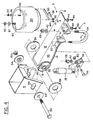
- Figure 4 is an exploded view of the component parts of an embodiment of the present invention;
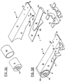
- Figure 5A is an exploded view of the component parts of a beam construction, according to the present invention;
- Figure 5B is an isometric view of the component parts shown in Figure 5A, in an assembled state; and
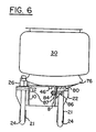
- Figure 6 is an end view taken along line A-A in Figure 1 of a vehicle suspension system, according to the present invention.
- With reference first to Figure 1, there is illustrated an advantageous environment for use of the suspension system. A conventional vehicle (not shown), such as a truck or trailer having
longitudinal frame member 2 from whichaxle 20 extends in conventional fashion laterally across the vehicle at right angles to longitudinally extendingbeam assembly 3, is connected to ground-engaging wheels (not shown). Figure 1 shows one side of the suspension. The illustrated suspension is duplicated on the other side of the vehicle (not shown). In general, the suspension system includes, at each side of the vehicle frame, one end ofU-shaped beam assembly 3, pivotally connected toframe 2 of the vehicle byhanger bracket 4. The other end of U-shapedbeam assembly 3 is rigidly connected topedestal 76, such thatpedestal 76 is rigidly connected at its other end toair bag assembly 30, or similar device, that is disposed betweenpedestal 76 andframe 2.Beam assembly 3 moves about its pivotal connection. - Looking at Figure 1, in conjunction with Figures 4, 5A and 5B,
U-shaped beam assembly 3 is pivotally attached toframe 2 by means ofhanger bracket 4, viapivot connection 52.Plate 14,side plates cross-piece 12 are rigidly attached tocylindrical sleeve 48, preferably by welding. Inserted withinsleeve 48 isresilient bushing 6. The preferred bushing construction, for the purposes of this invention, is that as shown in Figures 5-7 of U.S. Patent No. US-A-4 166 640 which has been used very successfully for many years by the applicants. Such a bushing has become known as the "Tri-Functional" bushing. Such bushings usually contain aninner tube 52 for the resilient member. - Fastener
bolt 56 is passed throughfirst alignment collar 54,first aperture 68 inhanger bracket 4,first wear washer 58, liner (not shown), which is, preferably, constructed of Delrin or other similar material,inner metal sleeve 52 of bushing 6,second wear washer 58,second aperture 68,second alignment collar 54, and nut 60, in order to pivotally attachbeam assembly 3 tohanger bracket 4. After final alignment,adjustment collars 54 are fixed by welding tobracket 4. Such an assembly provides a ready means for initial alignment and repair. Other attaching means that do not require a manually releasable fastening means, but, instead, employ a single or double plate fastening means, may also be used, as shown in figures 1-3, and as are described in more detail in the commonly assigned patent application entitled Vehicle Suspension Beam Pivot Connection, U.S. Serial No. 452,631, filed December 19, 1989. - Also, as shown in figures 1, 4, 5A and 5B,
beam assembly 3 consists of six essential parts, which are U-shapedmember 5,integral cross-member 12,plates flanges 22. One-piece,U-shaped member 5 is constructed to include a pair of opposingsides cross-member 12. ThisU-shaped member 5 is preferably formed by a stamping and/or bending process.Plates second member 7.Plate 16 hasbend 78 adjacent one end. Thissecond member 7 is then rigidly secured, preferably by welding, to the open end ofU-shaped member 5, and along opposingsides cross-member 12. As can be seen, by bending the end ofplates axle 20 at substantially the same relative angles, an axle locus is provided between opposingsides flange 22 and the two ends of these plates. The importance of this is discussed below. -
Flanges 22 are rigidly secured togrooves 70 in opposingsides U-shaped member 5, preferably by welding. The terminal bent end ofplate 14 contacts and is rigidly secured to one offlanges 22 by welding atpoint 35, while the terminal bent end ofplate 16 contacts and is rigidly secured to theother flange 22 by welding atpoint 37.Torque boxes 9 are defined byvertical flanges 22, inclined portions ofplates plates axle 20. U-bolt 24 is placed aroundaxle 20, throughholes 72 inflanges 22 andwashers 42 andnuts 26 are attached to U-bolt 24 and tightened in order to secureaxle 20 tobeam assembly 3. Also,axle 20 can be secured toflanges 22 such that contact points 35 and 37 are created at the points whereplates contact flanges 22 andaxle 20.U-bolt spacer 21 is constructed such that it substantially encircles a portion ofaxle 20 and is secured toaxle 20.Axle 20 is shown in dotted lines to depict a range of various possible positions it may occupy during use. It is given that the angle ofbeam assembly 3, with respect toframe 2, would change as those positions were attained. The length and orientation ofshock absorber 18 would also change, as well as the dimensions ofair bag 30. - As shown in Figure 1, shock
absorber pivot plate 36 is secured to one offlanges 22 by means ofwasher 42 andnut 26. Shockabsorber pivot plate 36 includesholes 74 through whichfastener 38 is passed in order to secureshock absorber 18 to pivotplate 36, such that the shock absorber pivots at 28 relative tobeam 3. Nut 40 is attached tofastener 38 and tightened in order to secureshock absorber 18 to pivotplate 36. Alternatively,pivot plate 36 can be directly attached toflange 22, preferably by welding. Fewer pieces are required to attachshock absorber 18 toflange 22, which will reduce weight and cost, and substantially all forces created byshock absorber 18 nearpivot point 28 will be transferred toflange 22. The other end ofshock absorber 18 is attached tovehicle frame 2 by conventional means (not shown). - By this structure, such that there are formed contact points 35 and 37, respectively, between
plates flanges 22, many of the forces transmitted tobeam 3 by the axle, caused by deflections of the axle relative to frame 2, will be transferred toresilient bushing 6. Stated another way, because of this unique plate means 7, with an axle in place, many of the torsional forces created by the axle deflections which are experienced by the ground-engaging wheels that are caused by the terrain will be transferred through the axle tobeam 3 and on topivotal bushing 6, in a manner that still allows the axle to walk without stressing one of the individual parts of the axle attachment structure substantially more than any other of the individual parts of the axle attachment structure. This desired result is realized because opposingsides axle 20 is placed. This axle locus, in conjunction withcontacts flanges 22 andplates axle 20, i.e.,torque box 9. This box beam structure is further assisted in creating the even deflection distribution acrossaxle 20 byU-bolt 24 engagement. The deflections experienced byaxle 20 are distributed over the entire torque box becauseplate 16 allows any deflection experienced byaxle 20 to be substantially transferred fromaxle 20 totorque box 9, intosuspension beam 3 and, ultimately, tobushing 6. - Put another way, the deflection characteristics of the
axle 20 are approximately equal to the deflection characteristics oftorque box 9. The mechanical impedances of the axle beam structure andtorque box 9 are not only similar, but are such that minor variations can be accepted without over-stressing an individual element. The formation of the box beam structure byplates axle 20. The loads transferred to plate 16 are then substantially transferred to plate 14 throughweld 34. The loads are then substantially transferred fromplates cylindrical sleeve 48 and, ultimately, throughresilient bushing 6 intoframe 2. This integral structure allows for loads imposed byaxle 20 or the vehicle to be efficiently distributed and transmitted throughout the beam structure which provides essentially uniform stresses throughout the structure. This structure allows transference of substantially all articulation forces, which are the most severe forces imposed on the suspension and result in the largest beam loads and deflections to be transmitted toresilient bushing 6, without over-stressingaxle 20,torque box 9 orbeam assembly 3. Also, this structure is particularly well-suited to high strength, lightweight alloys and efficient use of materials. -
Height control valve 90, which is any well-known conventional valve, is secured tohanger bracket 4.Rod 92 is connected tovalve 90.Rod 92 is connected, in turn, to plate 94, which is connected in unison withshock absorber 18 atpivot point 28, to pivotplate 36. -
Air bag 30 is secured to frame 2 by threadedfastener connections air bag 30, and which mate withwashers 66 and 67 andnuts Fastener connection 63 is hollow in order to allow air to escape from or enter intoair bag 30 as controlled byheight control valve 90. - In the ride mode,
air bag 30, of course, accommodates most of the vertical deflections transferred by the axle tobeam assembly 3 from the road-engaging wheels. Conversely, in the roll mode of the vehicle, thebeam assembly 3 andbushing 6 will be the major elements involved in transmitting and accommodating axle deflections. - Figure 2 illustrates another embodiment of the suspension system. The elements in Figure 2 that correspond with the elements in Figures 1, 4, 5A and 5B are numbered the same as in Figures 1, 4, 5A and 5B. As can be seen in Figure 2,
beam assembly 3 has been inverted in order to adjust the ride height betweenframe 2 and the center ofaxle 20. Downwardly extendingside plates 32 are rigidly attached, preferably by welding, toU-bolt spacer 21 which goes substantially all the way across, which rides on top ofaxle 20. Also,shock bracket 36 is rigidly attached, preferably by welding tospacer 21.Spacer 21 is extended to become continuous across the top ofaxle 20. With respect to this particular embodiment of the present invention, as depicted in Figure 2, airbag support plate 50 is attached toside plates 32 in order to provide support forair bag assembly 30, which generally includespedestal 76. - Figure 3 illustrates a still further embodiment. The elements in Figure 3 that correspond with the elements in Figures 1, 4, 5A and 5B have the same reference numbers as shown in Figures 1, 4, 5A and 5B. With respect to this particular embodiment as depicted in Figure 3,
air bag assembly 30 has been made taller but can be smaller in diameter. Also, the end ofbeam assembly 3 which extends beyondaxle 20 and away frombushing 6 has been further extended such thatside plates 32 have been eliminated and airbag support plate 50a has been modified to be rigidly attached, preferably by welding, directly tobeam assembly 3. Finally,shock bracket 36 is rigidly attached, preferably by welding tospacer 21.Spacer 21 is extended to become continuous across the top ofaxle 20. - Figure 6 depicts the connection between
pedestal 76 andbeam assembly 3 for larger air bags, when the pedestal is at least twice as large as the width of the beam.Pedestal 76 is attached tobracket 80, preferably by welding or casting.Bolt fastener 86 is secured throughhole 82 inbracket 80 and ahole 87 inbeam assembly 3, whereuponnut 84 is threaded onfastener 86 andbracket 80 is secured tobeam assembly 3. In this respect,beam assembly 3 can be used as either a right-or-left-handed beam. Also, this connection reduces the size of the beam assembly width and the overall beam assembly weight, because the extra pedestal support plate has been eliminated. - The flexibility of use, as evidenced by Figures 1-3, is of particular importance, because there are many diverse vehicles that can utilize this beam suspension. It is to be noted that while Figure 1 is depicted as showing a higher design height, Figures 2 and 3 depict medium and low design heights, respectively. This becomes critical, in that allowances can be made to accommodate the various maximum design heights that are allowed in applications where a specific design height is required.
- Therefore, one of the advantages of this system that it reduces cost and manufacturing time, while still incorporating the aforementioned lighter weight aspects in a wide variety of vehicles, useful in varying geographical areas having different vehicle restrictions.
Claims (9)
- An axle suspension system for a wheeled vehicle, comprising a beam (3) having a resilient pivotal bushing (6, 52) attached at one end of the beam to a hanger bracket (4), a spring means (30) attached at the other end of the beam (3) opposite the bushing (6, 52) and an axle locus, the beam (3) extending longitudinally along the vehicle and including a first member (5) and at least one second member (7) rigidly attached to the first member (5), characterised in that the first member (5) is substantially U-shaped with two opposing sides (8, 10) integrally formed with a cross-member (12); in that the second member (7) is spaced away from the cross-member (12) and defines a portion of the axle locus, the second member (7) comprising a longitudinally extending plate means (14, 16) having a first end and a second end (see 37), the second end forming one side of the axle locus and a third end (see 35) intermediate the first and second ends forming a second side of the axle locus, the first, second and third ends (see 37, 35) being integrally connected by the plate means (14, 16); and in that the plate means (14, 16) spans and connects at least a portion of the opposing sides (8, 10) of the U-shaped first member (5).
- An axle suspension system as claimed in Claim 1, wherein the axle locus is further defined by longitudinally spaced laterally extending plates (22) which are connected to the second and third ends (37, 35), respectively, of the second member (7).
- An axle suspension system as claimed in Claim 2, wherein the axle locus further includes laterally spaced U-shaped bolts (24) for securing an axle (20) to the longitudinally spaced laterally extending plates (22).
- An axle suspension system as claimed in either Claim 2 or Claim 3, wherein the laterally extending plates (22) are made of a one-piece construction.
- An axle suspension system as claimed in any one of Claims 2 to 4, wherein the laterally extending plates (22) are rigidly attached to grooves (70) which are stamped in the beam (3).
- An axle suspension system as claimed in any one of Claims 2 to 5, wherein the second member (7) contacts the laterally extending plates (22) adjacent a bend (78) in the second member (7).
- An axle suspension system as claimed in any preceding Claim, wherein the resilient bushing (6) is surrounded by a cylindrical sleeve (52).
- An axle suspension system as claimed in any preceding Claim, wherein an air spring (30) having a pedestal (76) is attached to one end of the beam (3).
- An axle suspension system as claimed in Claim 8, wherein the pedestal (76) is at least twice as wide as the beam (3), the system further comprising a bracket means (80) and means (82, 84, 86, 87) for securing the bracket means to the pedestal (76) and to the beam (3) in order to provide support for the pedestal (76).
Applications Claiming Priority (2)
| Application Number | Priority Date | Filing Date | Title |
|---|---|---|---|
| US07/578,780 US5037126A (en) | 1990-09-07 | 1990-09-07 | Lightweight beam suspension system |
| US578780 | 1995-12-22 |
Publications (3)
| Publication Number | Publication Date |
|---|---|
| EP0474331A2 EP0474331A2 (en) | 1992-03-11 |
| EP0474331A3 EP0474331A3 (en) | 1992-03-25 |
| EP0474331B1 true EP0474331B1 (en) | 1994-08-17 |
Family
ID=24314287
Family Applications (1)
| Application Number | Title | Priority Date | Filing Date |
|---|---|---|---|
| EP91304894A Expired - Lifetime EP0474331B1 (en) | 1990-09-07 | 1991-05-30 | Lightweight beam suspension system |
Country Status (8)
| Country | Link |
|---|---|
| US (1) | US5037126A (en) |
| EP (1) | EP0474331B1 (en) |
| AU (1) | AU631071B2 (en) |
| BR (1) | BR9102874A (en) |
| CA (1) | CA2043786C (en) |
| DE (1) | DE69103498T2 (en) |
| ES (1) | ES2059060T3 (en) |
| MX (1) | MX9100756A (en) |
Families Citing this family (81)
| Publication number | Priority date | Publication date | Assignee | Title |
|---|---|---|---|---|
| US5116075A (en) * | 1990-12-05 | 1992-05-26 | Lear Siegler Truck Products Corp. | Trailing arm suspension with wrapper compression axle mounting |
| US5171036A (en) * | 1991-08-27 | 1992-12-15 | The Boler Company | Rebound strap |
| AU666572B2 (en) * | 1992-10-19 | 1996-02-15 | Hendrickson International Corporation | Axle suspension systems |
| US5393096A (en) * | 1993-03-02 | 1995-02-28 | Nai Neway, Inc. | Suspension frame bracket |
| US5333896A (en) * | 1993-04-20 | 1994-08-02 | Creighton Brad M | Bird cage type suspension with bearing connected to axle tube |
| US5375871A (en) * | 1993-07-02 | 1994-12-27 | Ridewell Corporation | Vehicle suspension system comprising a wide base beam and axle shell |
| US5639110A (en) * | 1994-04-14 | 1997-06-17 | Nai Neway, Inc. | Trailing arm suspension |
| AU706633B2 (en) * | 1994-04-14 | 1999-06-17 | Nai Neway, Inc. | Trailing arm |
| US5427404A (en) * | 1994-06-15 | 1995-06-27 | Paccar Inc. | Stiff beam suspension system |
| US5667231A (en) * | 1995-09-14 | 1997-09-16 | Dakota Mfg. Co., Inc. | Trailer |
| US5649719A (en) | 1996-02-23 | 1997-07-22 | The Boler Company. | Linkage suspension system |
| US5788263A (en) * | 1996-05-09 | 1998-08-04 | Suspensions Incorporated | Suspension system with laminated beams |
| US5690353A (en) * | 1996-05-09 | 1997-11-25 | Suspensions Incorporated | Suspension system with improved beam |
| DE29616257U1 (en) * | 1996-09-19 | 1996-11-07 | Otto Sauer Achsenfabrik Keilberg, 63856 Bessenbach | Suspension for air suspension vehicle wheel axle |
| US5810377A (en) * | 1997-01-21 | 1998-09-22 | The Boler Company | Fabricated steer axle |
| US5988672A (en) * | 1997-08-11 | 1999-11-23 | Meritor Heavy Vehicle Suspension Systems, Inc. | Suspension system with integral box beam |
| US6039336A (en) * | 1997-09-19 | 2000-03-21 | Otto Sauer Achsenfabrik Keilberg | Vehicle axle suspension assembly |
| EP0906840B1 (en) * | 1997-10-04 | 2004-01-02 | Otto Sauer Achsenfabrik Keilberg | Axle suspension for vehicles |
| NZ508728A (en) | 1998-07-02 | 2002-11-26 | Boler Co | Trailing arm axle/suspension system with a weld in at least one opening in the mounting plate so as to weld the mounting plate to the axle |
| US6209895B1 (en) * | 1998-12-03 | 2001-04-03 | Reyco Industries, Inc. | Axle suspension system for a wheeled vehicle |
| US6340165B1 (en) | 1999-08-20 | 2002-01-22 | Gary L. Kelderman | Torsion axle and air bag vehicle suspension system |
| US6585223B1 (en) | 1999-09-14 | 2003-07-01 | Meritor Heavy Vehicle Suspensions, Inc. | Variable compliance bushing |
| NZ524252A (en) * | 2000-07-20 | 2004-03-26 | Lauras As | Cox-2 inhibitors for treating HIV and AIDS |
| GB0021718D0 (en) * | 2000-09-05 | 2000-10-18 | Meritor Heavy Vehicle Sys Ltd | Vehicle suspension beam |
| GB0021716D0 (en) * | 2000-09-05 | 2000-10-18 | Meritor Heavy Vehicle Sys Ltd | Vehicle suspension axle wrap |
| DE10105849A1 (en) * | 2001-02-08 | 2002-08-14 | Deere & Co | Suspension and round baler |
| US6557875B2 (en) * | 2001-03-21 | 2003-05-06 | Dana Corporation | Vehicle suspension |
| US6508393B2 (en) | 2001-03-22 | 2003-01-21 | Watson & Chalin Manufacturing, Inc. | Suspension system including arm having zero clearance axle connection |
| US6709014B2 (en) * | 2001-08-22 | 2004-03-23 | Volvo Trucks North America, Inc. | Heavy duty vehicle frame |
| US6854749B2 (en) * | 2001-10-31 | 2005-02-15 | International Truck Intellectual Property Company, Llc | Assembly with clamp-force-check-component |
| US7207583B2 (en) * | 2002-01-16 | 2007-04-24 | Hendrickson Usa, L.L.C. | Spacer apparatus for suspension beam bushing assemblies |
| US6733020B2 (en) * | 2002-07-12 | 2004-05-11 | Arvinmeritor Technology, Llc | Suspension trailing arm |
| US7967307B2 (en) * | 2002-07-12 | 2011-06-28 | Arvinmeritor Technology, Llc | Heavy duty trailing arm suspension system |
| US6843490B2 (en) | 2002-08-02 | 2005-01-18 | Ridewell Corporation | Suspension beam and bush attachment assembly |
| US6827360B2 (en) * | 2002-10-24 | 2004-12-07 | Arvinmeritor Technology, Llc | One-piece trailing arm section |
| US6752407B2 (en) * | 2002-11-13 | 2004-06-22 | International Truck Intellectual Property Company, Llc | Spring-mounting arrangement |
| GB2396140C (en) * | 2002-12-13 | 2011-06-23 | Meritor Heavy Vehicle Sys Ltd | A suspension trailing arm and method of making a suspension trailing arm |
| CA2443753C (en) * | 2003-10-22 | 2009-02-17 | Kelly W. Yakimishyn | Air suspension system for a vehicle |
| US7510197B2 (en) * | 2004-02-04 | 2009-03-31 | Gottschalk Michael J | Multi-piece axle and suspension |
| US7445220B2 (en) * | 2004-02-06 | 2008-11-04 | Daimler Trucks North America Llc | Vehicle axle apparatus |
| US7270341B2 (en) * | 2004-08-13 | 2007-09-18 | Ford Global Technologies, Llc | Vehicle suspension with improved radius arm to axle attachment |
| US20060113741A1 (en) * | 2004-12-01 | 2006-06-01 | Chalin Thomas N | Suspension system having high strength arm to axle connection |
| US7347435B2 (en) * | 2005-01-14 | 2008-03-25 | Watson & Chalin Manufacturing, Inc. | Suspension system having reduced weight arm construction |
| US20060158023A1 (en) * | 2005-01-14 | 2006-07-20 | The Boler Company | Continuous radius axle and fabricated spindle assembly |
| US20060181047A1 (en) * | 2005-02-14 | 2006-08-17 | Chamberlin Michael A | Trailing arm for a vehicle suspension |
| US7416200B2 (en) * | 2005-05-13 | 2008-08-26 | Saf-Holland, Inc. | Vehicle suspension assembly |
| US7646035B2 (en) * | 2006-05-31 | 2010-01-12 | Cree, Inc. | Packaged light emitting devices including multiple index lenses and multiple index lenses for packaged light emitting devices |
| US8835952B2 (en) | 2005-08-04 | 2014-09-16 | Cree, Inc. | Submounts for semiconductor light emitting devices and methods of forming packaged light emitting devices including dispensed encapsulants |
| DE102005038274C5 (en) † | 2005-08-12 | 2018-01-11 | Saf-Holland Gmbh | wheel suspension arm |
| JP2009538536A (en) * | 2006-05-26 | 2009-11-05 | クリー エル イー ディー ライティング ソリューションズ インコーポレイテッド | Solid state light emitting device and method of manufacturing the same |
| US7618049B2 (en) * | 2006-09-15 | 2009-11-17 | Arvinmeritor Technology, Llc | Trailing arm suspension |
| MX2007011491A (en) * | 2006-09-18 | 2009-02-05 | Waltco Truck Equipment Company | Multifunctional bushing connection between liftgate platform and load transfer members. |
| US8764037B2 (en) * | 2009-11-10 | 2014-07-01 | Vdl Weweler B.V. | Wheel axle suspension having clamp bodies with a protrusion for attaching an indented tubular axle to trailing arms |
| AU2011205667B2 (en) | 2010-01-18 | 2015-01-22 | Hendrickson Usa, L.L.C. | Heavy-duty axle-to-beam connection |
| CA2738999C (en) * | 2010-05-04 | 2017-12-05 | Timbren Industries Inc. | Independent suspension mechanism |
| US8979105B2 (en) * | 2010-12-17 | 2015-03-17 | Bbs Development, Llc | Adjustable mounting assembly for vehicle leaf spring |
| US8998229B2 (en) * | 2011-08-31 | 2015-04-07 | John Michel | I-beam axle suspension system |
| CA2862695C (en) | 2012-01-31 | 2016-03-15 | Hendrickson Usa, L.L.C. | Hanger arrangement for heavy-duty vehicle axle/suspension systems |
| US8955860B2 (en) | 2012-03-28 | 2015-02-17 | Saf-Holland, Inc. | Vehicle suspension assembly with integrated torque member and trailing arm mount |
| DE102012106152A1 (en) * | 2012-07-09 | 2014-01-09 | Schmitz Cargobull Ag | Suspension control arm and axle assembly for a non-driven axle of a vehicle, in particular a commercial vehicle |
| WO2014043617A1 (en) * | 2012-09-17 | 2014-03-20 | Hendrickson Usa, L.L.C. | Heavy-duty axle/suspension system |
| CN103085623B (en) * | 2013-01-25 | 2015-11-18 | 中国公路车辆机械有限公司 | A kind of supporting bridge air suspension |
| AU2014287027C1 (en) | 2013-07-12 | 2017-09-21 | Hendrickson Usa, L.L.C. | Mechanical axle/suspension spring seats for thin-wall axles |
| DE102013218028B4 (en) * | 2013-09-10 | 2015-12-03 | Saf-Holland Gmbh | axle connection |
| US9452640B2 (en) | 2014-03-26 | 2016-09-27 | Bbs Development Llc | Axle alignment system for multi-axle trailers |
| US9315083B2 (en) * | 2014-07-15 | 2016-04-19 | Hendrickson Usa, L.L.C. | Frame hanger for providing thrust angle alignment in vehicle suspension |
| WO2016106450A1 (en) * | 2014-12-31 | 2016-07-07 | Marshall Dale R | Screen assembly for a vibrating screening machine |
| US9333826B1 (en) * | 2015-03-04 | 2016-05-10 | Arvinmeritor Technology, Llc | Axle suspension system and method of manufacture |
| CN107405970B (en) | 2015-03-20 | 2019-09-06 | 亨德里克森美国有限责任公司 | Hangers for axle/suspension systems |
| US9809073B2 (en) | 2015-09-29 | 2017-11-07 | Hendrickson Usa, L.L.C. | Tapered axle/suspension system beam for heavy-duty vehicles |
| CA3005659C (en) | 2015-12-10 | 2020-07-14 | Hendrickson Usa, L.L.C. | Pivotal connection for heavy-duty vehicle suspension assembly |
| US9776677B2 (en) | 2016-02-10 | 2017-10-03 | Kelly W YAKIMISHYN | Lift axle suspension |
| BR202017023671Y1 (en) * | 2017-11-01 | 2022-10-11 | Castertech Fundição E Tecnologia Ltda | CONSTRUCTION ARRANGEMENT INSERTED IN BUSHING FOR PNEUMATIC SUSPENSION ARM |
| BR102018067286B1 (en) * | 2018-08-31 | 2024-01-23 | Castertech Fundição E Tecnologia Ltda | PNEUMATIC SUSPENSION ARM AND ASSEMBLY METHOD |
| US11130380B2 (en) * | 2018-09-18 | 2021-09-28 | Caterpillar Inc. | Wear disc for suspension |
| US10843519B2 (en) * | 2019-03-28 | 2020-11-24 | Zoomlion Heavy Indsutry Na, Inc. | Independent front axle suspension |
| US11407270B2 (en) | 2019-04-15 | 2022-08-09 | Rv Ride Control Llc | Adjustable spring mounting assembly for vehicle |
| US11813918B2 (en) | 2021-08-30 | 2023-11-14 | Hendrickson Usa, L.L.C. | Axle/suspension system for heavy-duty vehicles |
| US12187092B2 (en) | 2022-08-11 | 2025-01-07 | Rv Ride Control, Llc | Tandem axle suspension system with keeper having sliding slipper blocks |
| EP4719788A1 (en) | 2023-05-31 | 2026-04-08 | Hendrickson USA, L.L.C. | Axle-to-beam connection for heavy-duty vehicle axle/suspension systems |
| US12623722B2 (en) * | 2024-05-03 | 2026-05-12 | Timbren Industries, Inc. | Suspension unit having camber and/or toe adjustment mechanism for suspending a wheel and tire assembly from a vehicle frame |
Family Cites Families (34)
| Publication number | Priority date | Publication date | Assignee | Title |
|---|---|---|---|---|
| CA650987A (en) * | 1962-10-23 | D. Mclean Allan | Air-ride truck suspension | |
| US2367817A (en) * | 1939-09-13 | 1945-01-23 | Firestone Tire & Rubber Co | Vehicle suspension |
| US2352446A (en) * | 1941-09-23 | 1944-06-27 | Robert W Pointer | Spring support for motor vehicles |
| US2882067A (en) * | 1953-11-06 | 1959-04-14 | Gouirand Rene | Pneumatic vehicle suspension |
| FR1132451A (en) * | 1955-05-31 | 1957-03-12 | Spring suspension device for motor vehicles | |
| FR1140636A (en) * | 1956-01-17 | 1957-07-31 | Additional suspension device more particularly intended for motor vehicles with independent wheels and suspension with helical springs | |
| US2879077A (en) * | 1956-02-02 | 1959-03-24 | Youngstown Steel Car Corp | Air cushion suspension for single axles |
| US2952474A (en) * | 1956-02-23 | 1960-09-13 | Gouirand Rene | Pneumatic suspension for vehicles |
| US2879076A (en) * | 1958-01-22 | 1959-03-24 | Highway Trailer Co | Vehicle tandem axle air suspension |
| US3120396A (en) * | 1959-11-10 | 1964-02-04 | Daimler Benz Ag | Frame bearer construction, especially vehicles |
| NL302468A (en) * | 1961-05-11 | |||
| US3434707A (en) * | 1966-06-02 | 1969-03-25 | John E Raidel | Suspensions |
| US3828881A (en) * | 1972-11-30 | 1974-08-13 | Gen Motors Corp | Annular dessicant tank for air leveling systems |
| US3861708A (en) * | 1973-10-18 | 1975-01-21 | Twm Mfg Co | High strength auxiliary axle suspension system for low frame wheeled vehicles |
| US4132433A (en) * | 1976-07-19 | 1979-01-02 | Willetts Elwood H | Multiple axle suspension system |
| US4114923A (en) * | 1976-10-01 | 1978-09-19 | Raidel John E | Air spring and beam suspension |
| US4293145A (en) * | 1978-02-28 | 1981-10-06 | Taylor Glenn E | Auxiliary lift axle wheel assembly |
| US4195856A (en) * | 1978-03-01 | 1980-04-01 | Oshkosh Truck Corporation | High lift tag axle load transfer system |
| US4261597A (en) * | 1979-04-12 | 1981-04-14 | Turner Quick-Lift Corporation | Axle alignment mechanism and method |
| US4331348A (en) * | 1980-01-09 | 1982-05-25 | Raidel John E | Vehicle suspension |
| US4371190A (en) * | 1980-01-28 | 1983-02-01 | Turner Quick-Lift Corporation | Axle suspension system |
| US4529224A (en) * | 1981-05-21 | 1985-07-16 | Raidel John E | Wide base air spring suspension assembly |
| US4427213A (en) * | 1982-01-21 | 1984-01-24 | Raidel Jr John E | Vehicle suspension with rigid torque beam |
| US4494771A (en) * | 1982-01-21 | 1985-01-22 | Raidel John E | Suspension system with U-joint mounted load carrying torque arm |
| US4541653A (en) * | 1982-09-30 | 1985-09-17 | Raidel John E | Air spring suspension with angular torque beam, U-joint mount therefor, and lateral guides |
| US4501437A (en) * | 1983-04-21 | 1985-02-26 | Dorso Trailer Sales, Inc. | Load transfer axle assembly |
| DE3333171A1 (en) * | 1983-09-14 | 1985-03-28 | Otto Sauer Achsenfabrik Keilberg, 8751 Bessenbach | AXLE LIFTING DEVICE FOR AIR SUSPENSED VEHICLE AXLE |
| US4566719A (en) * | 1984-02-17 | 1986-01-28 | Turner Quick Lift Corporation | Spaced axle-to-beam connection for suspension of the rigid beam type |
| US4615539A (en) * | 1985-02-06 | 1986-10-07 | Lear Siegler, Inc. | Suspension for automotive vehicles |
| DE3521856A1 (en) * | 1985-06-19 | 1987-01-02 | Schmitz Anhaenger Fahrzeugbau | Air spring swivelling lever for vehicles, especially for trucks |
| US4722549A (en) * | 1987-02-05 | 1988-02-02 | Raidel John E | Suspension system with universal pivot connection between axle seat and torque rod |
| US4763923A (en) * | 1987-03-02 | 1988-08-16 | Raidel John E | Suspension assembly with air spring and self contained air lift spring |
| US4768808A (en) * | 1987-06-22 | 1988-09-06 | American Motors Corporation | Axle beam and steering assembly mount |
| US4991868A (en) * | 1989-12-19 | 1991-02-12 | The Boler Company | Vehicle suspension beam pivot connection |
-
1990
- 1990-09-07 US US07/578,780 patent/US5037126A/en not_active Expired - Lifetime
-
1991
- 1991-05-30 DE DE69103498T patent/DE69103498T2/en not_active Expired - Lifetime
- 1991-05-30 ES ES91304894T patent/ES2059060T3/en not_active Expired - Lifetime
- 1991-05-30 EP EP91304894A patent/EP0474331B1/en not_active Expired - Lifetime
- 1991-06-03 CA CA002043786A patent/CA2043786C/en not_active Expired - Lifetime
- 1991-06-28 AU AU79432/91A patent/AU631071B2/en not_active Expired
- 1991-07-09 BR BR919102874A patent/BR9102874A/en not_active IP Right Cessation
- 1991-08-21 MX MX9100756A patent/MX9100756A/en unknown
Also Published As
| Publication number | Publication date |
|---|---|
| DE69103498T2 (en) | 1994-12-08 |
| MX9100756A (en) | 1992-06-05 |
| EP0474331A3 (en) | 1992-03-25 |
| ES2059060T3 (en) | 1994-11-01 |
| DE69103498D1 (en) | 1994-09-22 |
| CA2043786C (en) | 1992-12-22 |
| CA2043786A1 (en) | 1992-12-22 |
| AU7943291A (en) | 1992-03-12 |
| EP0474331A2 (en) | 1992-03-11 |
| BR9102874A (en) | 1992-04-28 |
| AU631071B2 (en) | 1992-11-12 |
| US5037126A (en) | 1991-08-06 |
Similar Documents
| Publication | Publication Date | Title |
|---|---|---|
| US5037126A (en) | Lightweight beam suspension system | |
| CA2108724C (en) | Axle suspension system | |
| US5203585A (en) | Split-beam suspension system | |
| US6105984A (en) | Independent coil spring suspension for driven wheels | |
| US6116626A (en) | Independent front suspension | |
| EP1339555B1 (en) | Vehicle suspension assembly | |
| EP0190725B1 (en) | Suspension for automotive vehicles | |
| US5538274A (en) | Modular Independent coil spring suspension | |
| CA2030027C (en) | Suspension with stiffener arm | |
| EP0287278A1 (en) | A vehicle chassis transverse structural member | |
| US6808192B1 (en) | Trailing arm suspension | |
| CA2056608C (en) | Tandem wheel and axle suspension | |
| AU2002232766A1 (en) | Vehicle suspension assembly | |
| WO1998017487A1 (en) | Trailing arm suspension with articulated axle mounting | |
| EP1250237B1 (en) | Trailing arm suspension | |
| EP0939703A1 (en) | Full load-share coilspring bogie suspension | |
| CA1192919A (en) | Vehicle wheel suspension | |
| AU2023336527A1 (en) | Axle structure for a commercial vehicle chassis having an axle bridge | |
| MXPA93006307A (en) | Axle suspension system for overhead vehicles | |
| NZ272361A (en) | Vehicle axle rigidly attached to beam allowing for attaching braking mechanism to beam, rather than axle | |
| NZ215090A (en) | Vehicle suspension system; axle connected to pivoting arms using braced plates with mounting lugs | |
| AU5742398A (en) | Full load-share coilspring bogie suspension | |
| WO2001060646A1 (en) | Front suspension system for a wheeled vehicle |
Legal Events
| Date | Code | Title | Description |
|---|---|---|---|
| PUAI | Public reference made under article 153(3) epc to a published international application that has entered the european phase |
Free format text: ORIGINAL CODE: 0009012 |
|
| PUAL | Search report despatched |
Free format text: ORIGINAL CODE: 0009013 |
|
| AK | Designated contracting states |
Kind code of ref document: A2 Designated state(s): DE ES FR GB IT SE |
|
| AK | Designated contracting states |
Kind code of ref document: A3 Designated state(s): DE ES FR GB IT SE |
|
| 17P | Request for examination filed |
Effective date: 19920410 |
|
| 17Q | First examination report despatched |
Effective date: 19930318 |
|
| GRAA | (expected) grant |
Free format text: ORIGINAL CODE: 0009210 |
|
| AK | Designated contracting states |
Kind code of ref document: B1 Designated state(s): DE ES FR GB IT SE |
|
| REF | Corresponds to: |
Ref document number: 69103498 Country of ref document: DE Date of ref document: 19940922 |
|
| ITF | It: translation for a ep patent filed | ||
| ET | Fr: translation filed | ||
| REG | Reference to a national code |
Ref country code: ES Ref legal event code: FG2A Ref document number: 2059060 Country of ref document: ES Kind code of ref document: T3 |
|
| EAL | Se: european patent in force in sweden |
Ref document number: 91304894.8 |
|
| PLBE | No opposition filed within time limit |
Free format text: ORIGINAL CODE: 0009261 |
|
| STAA | Information on the status of an ep patent application or granted ep patent |
Free format text: STATUS: NO OPPOSITION FILED WITHIN TIME LIMIT |
|
| 26N | No opposition filed | ||
| REG | Reference to a national code |
Ref country code: GB Ref legal event code: IF02 |
|
| REG | Reference to a national code |
Ref country code: GB Ref legal event code: 732E |
|
| PGFP | Annual fee paid to national office [announced via postgrant information from national office to epo] |
Ref country code: FR Payment date: 20100525 Year of fee payment: 20 Ref country code: ES Payment date: 20100524 Year of fee payment: 20 |
|
| PGFP | Annual fee paid to national office [announced via postgrant information from national office to epo] |
Ref country code: IT Payment date: 20100513 Year of fee payment: 20 Ref country code: DE Payment date: 20100531 Year of fee payment: 20 |
|
| PGFP | Annual fee paid to national office [announced via postgrant information from national office to epo] |
Ref country code: GB Payment date: 20100401 Year of fee payment: 20 Ref country code: SE Payment date: 20100507 Year of fee payment: 20 |
|
| REG | Reference to a national code |
Ref country code: DE Ref legal event code: R071 Ref document number: 69103498 Country of ref document: DE |
|
| REG | Reference to a national code |
Ref country code: GB Ref legal event code: PE20 Expiry date: 20110529 |
|
| REG | Reference to a national code |
Ref country code: SE Ref legal event code: EUG |
|
| PG25 | Lapsed in a contracting state [announced via postgrant information from national office to epo] |
Ref country code: GB Free format text: LAPSE BECAUSE OF EXPIRATION OF PROTECTION Effective date: 20110529 |
|
| PG25 | Lapsed in a contracting state [announced via postgrant information from national office to epo] |
Ref country code: DE Free format text: LAPSE BECAUSE OF EXPIRATION OF PROTECTION Effective date: 20110531 |
|
| REG | Reference to a national code |
Ref country code: ES Ref legal event code: FD2A Effective date: 20130718 |
|
| PG25 | Lapsed in a contracting state [announced via postgrant information from national office to epo] |
Ref country code: ES Free format text: LAPSE BECAUSE OF EXPIRATION OF PROTECTION Effective date: 20110531 |