EP0474269B1 - Long period pendulum damping equipment - Google Patents
Long period pendulum damping equipment Download PDFInfo
- Publication number
- EP0474269B1 EP0474269B1 EP91201812A EP91201812A EP0474269B1 EP 0474269 B1 EP0474269 B1 EP 0474269B1 EP 91201812 A EP91201812 A EP 91201812A EP 91201812 A EP91201812 A EP 91201812A EP 0474269 B1 EP0474269 B1 EP 0474269B1
- Authority
- EP
- European Patent Office
- Prior art keywords
- rods
- rod
- pivoted
- tie beam
- gear
- Prior art date
- Legal status (The legal status is an assumption and is not a legal conclusion. Google has not performed a legal analysis and makes no representation as to the accuracy of the status listed.)
- Expired - Lifetime
Links
- 238000013016 damping Methods 0.000 title claims description 27
- 230000014509 gene expression Effects 0.000 description 20
- 230000010355 oscillation Effects 0.000 description 7
- 239000000725 suspension Substances 0.000 description 6
- 238000006073 displacement reaction Methods 0.000 description 3
- 230000001133 acceleration Effects 0.000 description 2
- 238000010276 construction Methods 0.000 description 2
- 230000000694 effects Effects 0.000 description 2
- 238000009434 installation Methods 0.000 description 2
- 238000005381 potential energy Methods 0.000 description 2
- 230000004048 modification Effects 0.000 description 1
- 238000012986 modification Methods 0.000 description 1
- 230000000087 stabilizing effect Effects 0.000 description 1
- 230000001360 synchronised effect Effects 0.000 description 1
Images

Classifications
-
- E—FIXED CONSTRUCTIONS
- E04—BUILDING
- E04H—BUILDINGS OR LIKE STRUCTURES FOR PARTICULAR PURPOSES; SWIMMING OR SPLASH BATHS OR POOLS; MASTS; FENCING; TENTS OR CANOPIES, IN GENERAL
- E04H9/00—Buildings, groups of buildings or shelters adapted to withstand or provide protection against abnormal external influences, e.g. war-like action, earthquake or extreme climate
- E04H9/02—Buildings, groups of buildings or shelters adapted to withstand or provide protection against abnormal external influences, e.g. war-like action, earthquake or extreme climate withstanding earthquake or sinking of ground
- E04H9/021—Bearing, supporting or connecting constructions specially adapted for such buildings
- E04H9/0215—Bearing, supporting or connecting constructions specially adapted for such buildings involving active or passive dynamic mass damping systems
-
- F—MECHANICAL ENGINEERING; LIGHTING; HEATING; WEAPONS; BLASTING
- F16—ENGINEERING ELEMENTS AND UNITS; GENERAL MEASURES FOR PRODUCING AND MAINTAINING EFFECTIVE FUNCTIONING OF MACHINES OR INSTALLATIONS; THERMAL INSULATION IN GENERAL
- F16F—SPRINGS; SHOCK-ABSORBERS; MEANS FOR DAMPING VIBRATION
- F16F7/00—Vibration-dampers; Shock-absorbers
- F16F7/10—Vibration-dampers; Shock-absorbers using inertia effect
- F16F7/1022—Vibration-dampers; Shock-absorbers using inertia effect the linear oscillation movement being converted into a rotational movement of the inertia member, e.g. using a pivoted mass
Definitions
- Fig. 4 is a partial plan view of the activated example shown in Fig. 3.
- ⁇ h1 and ⁇ h2 are expressed by the following expressions (8) and (9), respectively.
- ⁇ h 1 -l 11 (1 - cos ⁇ 2 ) ⁇ -l 1 ⁇ 2 2 2
- ⁇ h 2 (l 12 - l 11 ) (1 - cos ⁇ 2 ) ⁇ (l 12 - l 11 ) ⁇ 2 2 2
- the potential energy U is expressed by the following expression.
- the gears 13a and 13b having the same size which have the shorter rod 11 and the longer rod 12 engage with each other have been adopted, but it is possible to make the overall height lower and obtain the oscillation frequency of a desired long period by adopting gears having a desired gear ratio and making the tilt angle of the longer rod 12 gear ratio times as large as that of the shorter rod 11.
Landscapes
- Engineering & Computer Science (AREA)
- Architecture (AREA)
- Business, Economics & Management (AREA)
- Emergency Management (AREA)
- Environmental & Geological Engineering (AREA)
- General Engineering & Computer Science (AREA)
- Civil Engineering (AREA)
- Structural Engineering (AREA)
- Mechanical Engineering (AREA)
- Vibration Prevention Devices (AREA)
- Buildings Adapted To Withstand Abnormal External Influences (AREA)
Description
- The present invention relates to a long period pendulum damping equipment applied to controlling of oscillation of a long period structure such as a skyscraper.
- Among damping equipments applied to long period structures, an equipment having a pendulum structure in which a weight is suspended with a wire and the like having a suspension length ℓ which has an almost equal period to a period of a structure has been known as an equipment which is operable from such a small acceleration that a human being does not feel it.
- Now, in such a skyscraper that requires damping countermeasures, a proper period reaches approximately 10 seconds sometimes, thus requiring to set the period of the damping equipment to almost the same. Here, when it is assumed that a pendulum length is ℓ and the gravitational acceleration is g, a period T of the pendulum is given by the following expression.

- In order to obtain a period of approximately 10 seconds, however, a pendulum having a suspension length of approximately 25 m is required from the relationship in above-mentioned expression, thus requiring an extensive space for setting the damping equipment.
- From JP-A-62031735 a damping equipment is known as described in the preamble of claim 1.
- It is the object of the invention to provide a damping equipment without having sliding portions.
- This is achieved by the features as defined in the characterizing part of
claim 1 or 2. - A first embodiment of the present invention for achieving above-mentioned object exists in a long period pendulum damping equipment comprising right and left pair of longer rods having an equal length with upper ends pivoted at upper ends thereof to a structure, respectively, at an appropriate interval and extending perpendicularly downward, a tie beam in a horizontal direction with right and left ends pivoted at lower ends of above-mentioned respective longer rods, shorter rods having an equal length extending perpendicularly upward with respective lower ends pivoted at right and left ends of above-mentioned tie beam, tilt angle interlocking means of both rods which are installed at right and left end portions of the tie beam and keep the tilt angle in one direction of above-mentioned longer rods with respect to the vertical line always equal to a tilt angle in another direction of above-mentioned shorter rods or certain ratio times as large as the tilt angle, and a weight having right and left ends pivoted at upper parts of above-mentioned respective shorter rods.
- A second embodiment of the present invention for achieving above-mentioned object exists in a long period pendulum damping equipment comprising right and left pair of shorter rods having an equal length pivoted at lower ends thereof to an objective structure at an appropriate interval, respectively, and extending perpendicularly upward, a tie beam in a horizontal direction pivoted at right and left portions thereof to upper ends of above-mentioned respective shorter rods, longer rods having an equal length pivoted at upper ends thereof to right and left portions of the tie beam, respectively, and extending perpendicularly downward, tilt angle interlocking means of both rods which are installed at the right and left portions of the tie beam, respectively, and keep the tilt angle in one direction of above-mentioned longer rods always equal to a tilt angle in another direction of above-mentioned shorter rods with respect to the vertical line or certain ratio times of the tilt angle, and a weight pivoted at right and left portions thereof to the lower parts of above-mentioned respective longer rods.
- According to the construction of the first embodiment of the present invention, the pendulum presents a V shape at the time of oscillation with a longer rod having the length of ℓ₁ and a shorter rod having a length of ℓ₂ and, when the mass of gears and tie beam is neglected, the period T is expressed as follows.

- As a result, a long period damping equipment is obtainable in spite of a comparatively low overall height depending on selection of length ℓ₁ and ℓ₂ of both rods.
- According to the construction of the second embodiment of the present invention, when it is assumed that the lengths of a shorter rod and the length of a longer rod joined together in an inverted V shape through a gear are ℓ₁₁ and ℓ₁₂, the mass of the gear and the tie beam is m₁₁, and the mass of the damping weight is m₁₂, the period T of a damping system of the present invention is expressed by following expressions when the mass of above-mentioned gear and tie beam is taken into consideration.


- A long period pendulum is obtainable in spite of a comparatively low overall height depending on selection of ℓ₁₁ and ℓ₁₂.
- Fig. 1 is a front view showing an embodiment according to the first gist of the present invention.
- Fig. 2 is a partial plan view of the embodiment shown in Fig. 1.
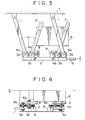
- Fig. 3 is a side view showing an activated example of the embodiment in Fig. 1.
- Fig. 4 is a partial plan view of the activated example shown in Fig. 3.
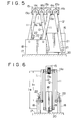
- Fig. 5 is a side view showing an embodiment according to the second gist of the present invention.
- Fig. 6 is a front view of the embodiment shown in Fig.5.
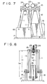
- Fig. 7 is a side view showing an activated example of the embodiment in Fig. 5.
- Fig. 8 is a front view of the activated example of the embodiment shown in Fig. 7.
- (1) First, an embodiment corresponding to above-mentioned first gist of the present invention will be described hereafter with reference to Fig. 1 thru Fig. 4.
- In Fig. 1 and Fig. 2, 1,1 denote comparatively long right and left pair of longer rods having a length of ℓ₁ with upper ends thereof pivoted respectively to an
objective structure 7 at an appropriate interval and hung down perpendicularly, and lower ends of respective longer rods 1 are pivoted at right and left ends of atie beam 5 which is comparatively light in weight by means ofpins 3a, respectively. - 2,2 denote comparatively short pair of shorter rods having a length of ℓ₂ which are pivoted at respective lower ends thereof in the vicinity of
pivot pins tie beam 5 by means ofpins shorter rod 2, which act to interlock both rods in a V shape so as to make a left tilt angle θ₁ and a right tilt angle θ₁' of the longer rod 1 and theshorter rod 2 with respect to the vertical line equal to each other by engaging these gears with each other. 6 denotes a weight pivoted to a plurality ofpin holes 2a bored at upper parts of theshorter rods pins 2b at right and left ends thereof, and 8 denotes an attenuator installed between thetie beam 5 and theobjective structure 7. - In the above equipment, if the
shorter rod 2 is tilted toward one side by the tilt angle θ₁ with respect to the vertical line when theweight 6 moves horizontally, the longer rod 1 is also tilted toward another side by the same tilt angle θ₁ through thegears - Thus, a horizontal displacement δ of the
weight 6 is expressed by an expression (1) within a range where θ₁ is comparatively small.
- Here, a vertical movement Δh of the
weight 6 is expressed by the expression (2).
- Thus, the potential energy U when the weight has moved to a position shown in the figure is obtained by an expression (3) in case the weight of the
gears tie beam 5 is neglected and the mass of the weight is at m.

- Thus, the period T is given by an expression (5).

- Here, when it is assumed that ℓ₁ is 2m and ℓ₂ is 1.5m, the period T becomes approximately 10 seconds. Thus, it becomes possible to obtain a long period at the suspension height of 2m, and it is also possible to obtain a long period at a low suspension height according to the present equipment.
- Besides, the period T is adjustable by supporting the
weight 6 while changing the length of the effective length ℓ₂ of theshorter rod 2. - Further, it is possible to provide a passive damping equipment with an attenuator having a short stroke by setting an
attenuator 8 to thetie beam 5. - In above-mentioned embodiment, the
gears shorter rod 2 engage with each other have the same size, but it is possible to make the overall height lower and obtain a desired oscillation frequency of a long period by adopting gears having a desired gear ratio for thegears shorter rod 2 gear ratio times as large as that of the longer rod 1. - Incidentally, above-mentioned embodiment can also be formed in an active damping equipment by driving the
gears 4b withservomotors 9 as shown in Fig. 3 and Fig. 4, respectively. - According to the above mentioned embodiment, the following effects are taken.
- ① It is possible to obtain a long period damping equipment at a low suspension height.
- ② Further, a compact active damping equipment having no sliding portion is obtainable by driving gears with servomotors and the like.
- (2) In the next place, an embodiment corresponding to above-mentioned second gist of the present invention will be described hereafter with reference to Fig. 5 thru Fig. 8.
- In Fig. 5 and Fig. 6, 11, 11 denote right and left pair of shorter rods having relatively short length ℓ₁₁ which are pivoted at low ends thereof at an appropriate interval, respectively, on a
support base 8 fixed to anobjective structure 17 and extend upward, and upper ends of respectiveshorter rods 11 are pivoted at right and left portions of atie beam 15 which is comparatively light in weight and has large rigidity by means of connectingpins 14a, respectively. - 12, 12 denote comparatively long right and left pair of longer rods having a length of ℓ₁₂ which are pivoted at upper ends thereof in the vicinity of connecting
pins shorter rods 11 at right and left portions of thetie beam 15 by means ofpins shorter rod 11 and thelonger rods 12, which act to interlock both rods in an inverted V shape so as to make a left tilt angle θ₂ and a right tilt angle θ₂' of theshorter rod 11 and thelonger rod 12 with respect to the vertical line equal to each other by having these gears engage with each other. - 16 denotes a weight pivoted by
support pins 21 to a plurality of pin holes bored at an equal interval at lower parts of thelonger rods weight 16, and an upper part of aguide rail 20 bored in a longitudinal direction on a floor surface of a structure is inserted loosely into thelongitudinal groove 19. - When the objective structure oscillates longitudinally and
weight 16 moves horizontally in the above structure, theshorter rod 11 is tilted by θ₂ in one direction, and thelonger rods gears - Thereupon, synchronous adjustment of the weight becomes possible with the length ℓ₁₂ variable for the reason described hereunder by having selected the position of the
support pin 21 in advance. - Namely, when it is assumed that the mass of the
gears tie beam 15 is m₁₁ and the mass ofweight 16 is m₁₂, the proper oscillation frequency f of theweight 6 is derived as follows. - A horizontal displacement δ₁ of the gear 13 and the
tie beam 15 and a horizontal displacement 62 of theweight 16 are obtained as expressed by following expressions (6) and (7) within a range in which θ₂ in Fig. 5 is comparatively small.

- Further, when it is assumed that a vertical movement (upward direction is positive) of the gear 13 and the
tie beam 15 is Δh₁ and a vertical movement (upward direction is positive) of theweight 16 is Δh₂, Δh₁ and Δh₂ are expressed by the following expressions (8) and (9), respectively.


- Accordingly, the oscillation frequency f is given by the following expression from the expressions (11) and (12).


- Since the equivalent pendulum length

- Besides, it is possible to provide a passive damping equipment in spite of an attenuator having a comparatively short stroke by installing an
attenuator 22 between theshorter rod 11 and thesupport base 18. - Presumably, when it is assumed that ℓ₁₁ = 1.5m; ℓ₁₂ = 2.5m; m₁₂ ≒ 5 m₁₁, an inverted V-shaped pendulum having a period of approximately 10 seconds is materialized.
- In above-mentioned embodiment, the
gears shorter rod 11 and thelonger rod 12 engage with each other have been adopted, but it is possible to make the overall height lower and obtain the oscillation frequency of a desired long period by adopting gears having a desired gear ratio and making the tilt angle of thelonger rod 12 gear ratio times as large as that of theshorter rod 11. - Furthermore, it is also possible to provide an active damping equipment by modifying the structure of above-mentioned embodiment to some extent so as to drive the shorter rod and the longer rod with a
servomotor 24 through areduction gear 23 as shown in Fig. 7 and Fig. 8. - According to the above embodiment and the modification example, the following effects are obtained.
- ① It is possible to obtain a damping equipment having a long period at a low suspension height, and an extensive space is not required for installation.
- ② A frame and the like for suspending a damping equipment are no longer required.
- ③ It is possible to obtain a compact active damping equipment having no sliding part by driving the gear portion with a servomotor and the like.
- (3) According to the present invention, a long period pendulum damping equipment in which the overall height is made as lowest as possible and that a long period is provided and it is possible to make the installation space small is provided. Hence, the present invention is very useful in the industrial field.
- Incidentally, as a driving unit in an active damping equipment, there are a unit having such a structure that a force is applied directly to the weight portion or the connecting beam portion by means of a servomotor and a ball screw installed in the objective structure in place of a structure in which rods are driven by means of a servomotor as described above, or a unit having such a structure that a slit is provided on the weight in parallel with the oscillation surface and a plate disposed with a linear motor is inserted into the slit portion for driving and so on.
Claims (3)
- A long period pendulum damping equipment comprising:a right and left pair of first longer rods (1, 1) having the same length with each one-end thereof pivoted to a structure (7) a distance apart from each other and extending downward;a tie beam (5) in a horizontal direction with right and left portions pivoted at the other ends of said first rods respectively;a pair of second shorter rods (2, 2) having the same length pivoted at each one end thereof to right and left portions of the tie beam (5) and extending upward;a weight (6) pivoted at right and left portions to the other ends of said second rods respectively,
characterized bya first gear (4a) integral with said first rod is provided at the pivot portion of said first rod toward the tie beam, said first gear (4a) making the same rotation as that of said first rod and a second gear (4b) integral with said second rod is provided at the pivot portion of said second rod toward the tie beam, said second gear (4b) making the same rotation as that of said second rod, said gears interlocking both rods in a V-shape so as to make the tilt angle in one direction of said second rods with respect to the vertical line always equal to a tilt angle in the other direction of said first rods with respect to the vertical line or certain ratio times of the tilt angle. - A long period pendulum damping equipment comprising:a right and left pair of first shorter rods (11, 11) having the same length with each one-end thereof pivoted to a structure (17) a distance apart from each other and extending upward;a tie beam (15) in a horizontal direction with right and left portions pivoted at the other ends of said first rods respectively;a pair of second longer rods (12, 12) having the same length pivoted at each one end thereof to right and left portions of the tie beam (15) and extending downward;a weight (16) pivoted at right and left portions to the other ends of said second rods respectively, characterized bya first gear (13a) integral with said first rod is provided at the pivot portion of said first rod toward the tie beam, said first gear (13a) making the same rotation as that of said first rod and a second gear (13b) integral with said second rod is provided at the pivot portion of said second rod toward the tie beam, said second gear (4b) making the same rotation as that of said second rod, said gears interlocking both rods in a reverse V-shape so as to make the tilt angle in one direction of said second rods with respect to the vertical line always equal to a tilt angle in the other direction of said first rods with respect to the vertical line or certain ratio times of the tilt angle.
- A long period pendulum damping equipment according to claim 1 or 2 characterized in that there is provided a drive unit (9, 24) which accelerates swinging of the pendulum.
Applications Claiming Priority (4)
| Application Number | Priority Date | Filing Date | Title |
|---|---|---|---|
| JP228740/90 | 1990-08-30 | ||
| JP2228740A JP2691062B2 (en) | 1990-08-30 | 1990-08-30 | Pendulum type long-period damping device |
| JP260596/90 | 1990-10-01 | ||
| JP26059690A JP2734488B2 (en) | 1990-10-01 | 1990-10-01 | Pendulum type long-period damping device |
Publications (2)
| Publication Number | Publication Date |
|---|---|
| EP0474269A1 EP0474269A1 (en) | 1992-03-11 |
| EP0474269B1 true EP0474269B1 (en) | 1996-03-27 |
Family
ID=26528435
Family Applications (1)
| Application Number | Title | Priority Date | Filing Date |
|---|---|---|---|
| EP91201812A Expired - Lifetime EP0474269B1 (en) | 1990-08-30 | 1991-07-10 | Long period pendulum damping equipment |
Country Status (7)
| Country | Link |
|---|---|
| US (1) | US5272847A (en) |
| EP (1) | EP0474269B1 (en) |
| AU (1) | AU641027B2 (en) |
| CA (1) | CA2048082C (en) |
| DE (1) | DE69118280T2 (en) |
| HK (1) | HK17997A (en) |
| NZ (1) | NZ238798A (en) |
Cited By (1)
| Publication number | Priority date | Publication date | Assignee | Title |
|---|---|---|---|---|
| CN104975663A (en) * | 2014-04-01 | 2015-10-14 | 东华理工大学 | Multi-plane quasi linear energy dissipating damper |
Families Citing this family (12)
| Publication number | Priority date | Publication date | Assignee | Title |
|---|---|---|---|---|
| JP3064733B2 (en) * | 1993-03-30 | 2000-07-12 | 寛 松久 | Dynamic vibration absorber of pendulum type structure |
| US5657597A (en) | 1995-04-11 | 1997-08-19 | Environmental Building Technology, Ltd. | Building construction method |
| EP1329565A1 (en) * | 2002-01-15 | 2003-07-23 | Alain Serge Charles Lacroix | Dynamic pendulous shock absorber |
| CA2531359A1 (en) * | 2005-12-22 | 2007-06-22 | Motioneering Inc. | Long period pendulum arrangement |
| GB2473659B (en) * | 2009-09-19 | 2012-04-11 | Bruce Gregory | Dynamically tuned wave energy conversion system |
| CN102383503A (en) * | 2011-08-26 | 2012-03-21 | 中国江西国际经济技术合作公司 | Truss imitating type damper structure transfer layer |
| US11353084B2 (en) * | 2013-03-15 | 2022-06-07 | Clearmotion Acquisition I Llc | Rotary actuator driven vibration isolation |
| CN104200723B (en) * | 2014-09-10 | 2016-09-28 | 宁波市鄞州青林医疗器械技术咨询有限公司 | Contact is from seeking formula zero moment of torsion physical pendulum rotating shaft processing technology |
| DE102016122999B4 (en) | 2016-11-29 | 2019-01-31 | Burkhard Dahl | Compact spatial ellipsoid mass pendulum |
| FR3059747B1 (en) * | 2016-12-02 | 2020-03-27 | Soletanche Freyssinet | TUNED DYNAMIC SHOCK ABSORBER |
| ES2982784T3 (en) * | 2017-08-08 | 2024-10-17 | Fm Energie Gmbh & Co Kg | Vibration absorber with rotary damper |
| DK180710B1 (en) * | 2019-05-24 | 2021-12-16 | Soh Wind Tunnels Aps | Pendulum mass damper |
Family Cites Families (6)
| Publication number | Priority date | Publication date | Assignee | Title |
|---|---|---|---|---|
| US1761322A (en) * | 1928-04-09 | 1930-06-03 | George W Anderson | Foundation construction |
| SE394881B (en) * | 1974-09-02 | 1977-07-18 | Linden Alimak Ab | KIT FOR DAMPING OF SWING AT CONSTRUCTIONS, EXV BUILDING CRANES AND DEVICE FOR THIS |
| JPS63135628A (en) * | 1986-11-26 | 1988-06-08 | Hitachi Ltd | Structure vibration isolator |
| US4935651A (en) * | 1987-12-04 | 1990-06-19 | Hyundai Heavy Industries Co., Ltd. | Automatically controlled dynamic absorber |
| JPH086487B2 (en) * | 1989-01-17 | 1996-01-24 | 鹿島建設株式会社 | Combined type vibration control / wind control device |
| IT1228988B (en) * | 1989-04-11 | 1991-07-12 | Fima Spa | ELASTOPLASTIC BEHAVIOR ENERGY DISSIPATOR, PARTICULARLY FOR USE IN ANTI-SEISMIC STRUCTURES. |
-
1991
- 1991-06-28 NZ NZ238798A patent/NZ238798A/en unknown
- 1991-07-03 AU AU80157/91A patent/AU641027B2/en not_active Ceased
- 1991-07-10 EP EP91201812A patent/EP0474269B1/en not_active Expired - Lifetime
- 1991-07-10 DE DE69118280T patent/DE69118280T2/en not_active Expired - Fee Related
- 1991-07-12 US US07/729,464 patent/US5272847A/en not_active Expired - Lifetime
- 1991-07-29 CA CA002048082A patent/CA2048082C/en not_active Expired - Fee Related
-
1997
- 1997-02-13 HK HK17997A patent/HK17997A/en not_active IP Right Cessation
Cited By (2)
| Publication number | Priority date | Publication date | Assignee | Title |
|---|---|---|---|---|
| CN104975663A (en) * | 2014-04-01 | 2015-10-14 | 东华理工大学 | Multi-plane quasi linear energy dissipating damper |
| CN104975663B (en) * | 2014-04-01 | 2018-03-13 | 东华理工大学 | A kind of more plane line of collimation energy-dissipating and shock-absorbing devices |
Also Published As
| Publication number | Publication date |
|---|---|
| US5272847A (en) | 1993-12-28 |
| CA2048082C (en) | 1995-04-25 |
| AU8015791A (en) | 1992-03-05 |
| HK17997A (en) | 1997-02-13 |
| CA2048082A1 (en) | 1992-03-01 |
| DE69118280T2 (en) | 1996-08-08 |
| EP0474269A1 (en) | 1992-03-11 |
| NZ238798A (en) | 1993-11-25 |
| AU641027B2 (en) | 1993-09-09 |
| DE69118280D1 (en) | 1996-05-02 |
Similar Documents
| Publication | Publication Date | Title |
|---|---|---|
| EP0474269A1 (en) | Long period pendulum damping equipment | |
| EP0361125B1 (en) | Damping device for tower-like structure | |
| EP0618380A1 (en) | Dynamic vibration absorber for pendulum type structure | |
| FI82758C (en) | Dynamic vibration damper | |
| US5127493A (en) | Linear motor elevator system | |
| KR20010101826A (en) | Device and method for adjusting seats in vehicles | |
| JP2778514B2 (en) | Partition wall | |
| US4486140A (en) | Device for the parking of automobiles | |
| JP2516576B2 (en) | Elastic-plastic damper | |
| EP3859187A1 (en) | Pendulum vibration damper | |
| JP2001050335A (en) | Damping device | |
| JPH09151658A (en) | Runner connection device for moving partition wall | |
| JP2734488B2 (en) | Pendulum type long-period damping device | |
| JP2691062B2 (en) | Pendulum type long-period damping device | |
| JPH08226252A (en) | Vibration control device with variable stiffness mechanism for high-rise buildings | |
| JP2706364B2 (en) | Pendulum type long-period damping device | |
| JP2670179B2 (en) | Pendulum damping device | |
| EP4571215A1 (en) | Vibration damping system in a solar tracker | |
| KR900008942Y1 (en) | Level adjustment device of partition | |
| US20250198661A1 (en) | Vibration damping system on a solar tracker | |
| RU2017027C1 (en) | Apparatus for damping oscillations | |
| JP3068302B2 (en) | Pendulum damping device | |
| JPS62214013A (en) | Opening and closing mechanism for cabin front window of construction machine vehicle | |
| JPH0331763Y2 (en) | ||
| SU1296456A1 (en) | Arrangement for hanging up vehicle |
Legal Events
| Date | Code | Title | Description |
|---|---|---|---|
| PUAI | Public reference made under article 153(3) epc to a published international application that has entered the european phase |
Free format text: ORIGINAL CODE: 0009012 |
|
| AK | Designated contracting states |
Kind code of ref document: A1 Designated state(s): DE FR GB IT |
|
| 17P | Request for examination filed |
Effective date: 19920522 |
|
| 17Q | First examination report despatched |
Effective date: 19931122 |
|
| GRAA | (expected) grant |
Free format text: ORIGINAL CODE: 0009210 |
|
| AK | Designated contracting states |
Kind code of ref document: B1 Designated state(s): DE FR GB IT |
|
| REF | Corresponds to: |
Ref document number: 69118280 Country of ref document: DE Date of ref document: 19960502 |
|
| ET | Fr: translation filed | ||
| ITF | It: translation for a ep patent filed | ||
| PLBE | No opposition filed within time limit |
Free format text: ORIGINAL CODE: 0009261 |
|
| STAA | Information on the status of an ep patent application or granted ep patent |
Free format text: STATUS: NO OPPOSITION FILED WITHIN TIME LIMIT |
|
| 26N | No opposition filed | ||
| PGFP | Annual fee paid to national office [announced via postgrant information from national office to epo] |
Ref country code: GB Payment date: 19990707 Year of fee payment: 9 |
|
| PGFP | Annual fee paid to national office [announced via postgrant information from national office to epo] |
Ref country code: FR Payment date: 19990709 Year of fee payment: 9 |
|
| PGFP | Annual fee paid to national office [announced via postgrant information from national office to epo] |
Ref country code: DE Payment date: 19990712 Year of fee payment: 9 |
|
| PG25 | Lapsed in a contracting state [announced via postgrant information from national office to epo] |
Ref country code: GB Free format text: LAPSE BECAUSE OF NON-PAYMENT OF DUE FEES Effective date: 20000710 |
|
| GBPC | Gb: european patent ceased through non-payment of renewal fee |
Effective date: 20000710 |
|
| PG25 | Lapsed in a contracting state [announced via postgrant information from national office to epo] |
Ref country code: FR Free format text: LAPSE BECAUSE OF NON-PAYMENT OF DUE FEES Effective date: 20010330 |
|
| REG | Reference to a national code |
Ref country code: FR Ref legal event code: ST |
|
| PG25 | Lapsed in a contracting state [announced via postgrant information from national office to epo] |
Ref country code: DE Free format text: LAPSE BECAUSE OF NON-PAYMENT OF DUE FEES Effective date: 20010501 |
|
| PG25 | Lapsed in a contracting state [announced via postgrant information from national office to epo] |
Ref country code: IT Free format text: LAPSE BECAUSE OF NON-PAYMENT OF DUE FEES;WARNING: LAPSES OF ITALIAN PATENTS WITH EFFECTIVE DATE BEFORE 2007 MAY HAVE OCCURRED AT ANY TIME BEFORE 2007. THE CORRECT EFFECTIVE DATE MAY BE DIFFERENT FROM THE ONE RECORDED. Effective date: 20050710 |