EP0474127A1 - Improved dishwashing machine - Google Patents
Improved dishwashing machine Download PDFInfo
- Publication number
- EP0474127A1 EP0474127A1 EP91114599A EP91114599A EP0474127A1 EP 0474127 A1 EP0474127 A1 EP 0474127A1 EP 91114599 A EP91114599 A EP 91114599A EP 91114599 A EP91114599 A EP 91114599A EP 0474127 A1 EP0474127 A1 EP 0474127A1
- Authority
- EP
- European Patent Office
- Prior art keywords
- spraying
- dishwashing machine
- organ
- apertures
- correspondence
- Prior art date
- Legal status (The legal status is an assumption and is not a legal conclusion. Google has not performed a legal analysis and makes no representation as to the accuracy of the status listed.)
- Withdrawn
Links
Images
Classifications
-
- A—HUMAN NECESSITIES
- A47—FURNITURE; DOMESTIC ARTICLES OR APPLIANCES; COFFEE MILLS; SPICE MILLS; SUCTION CLEANERS IN GENERAL
- A47L—DOMESTIC WASHING OR CLEANING; SUCTION CLEANERS IN GENERAL
- A47L15/00—Washing or rinsing machines for crockery or tableware
- A47L15/14—Washing or rinsing machines for crockery or tableware with stationary crockery baskets and spraying devices within the cleaning chamber
- A47L15/18—Washing or rinsing machines for crockery or tableware with stationary crockery baskets and spraying devices within the cleaning chamber with movably-mounted spraying devices
- A47L15/22—Rotary spraying devices
- A47L15/23—Rotary spraying devices moved by means of the sprays
Definitions
- the present invention refers to a dishwashing machine of the type comprising a washing chamber, at least one basket for containing the dishes and at least one spraying organ, fed through a water supply circuit and rotating around a substantially vertical axis.
- dishwashing machines are provided with spraying organs, whose length is slightly minor than the shortest side of the section of the washing chamber which contains them.
- the sprayer, or arm can freely rotate on a substantially horizontal plane and the area of the washing chamber section which is not interested by the rotating movement is function of the plan of the same chamber; this area is minimal in case of squared plan.
- This embodiment has always involved the use of spraying organs with a substantially straight principal axis, having a plurality of apertures through which the water jets which sprinkle the dishes exit.
- the improvement of the washing quality can be obtained just operating on the spraying organ, directly or indirectly.
- Italian patent application nr. 67077A/89 describes a dishwashing machine, with a washing chamber having a rectangular section, provided with two spraying arms rotating according to two vertical axis, which are staggered in respect of the chamber plan, in order to minimize the areas not covered directly by the washing jets.
- the French utility model nr. 7828597 describes a rotating arm for dishwashers, which sprinkles jets with a great kinetic energy even in case of low speed rotation. According to the embodiment therein, this is allowed by the arm shape: the cross section of its body increases from the center towards the ends, while on the contrary the dimensions of the spraying holes decrease from the center of the arm towards its ends.
- the spraying organs of the known type generally provide two thrust jets, inclined and positioned at the ends of the sprayer, which exit two apertures, each of them arranged on one of the two portions of the same prayer.
- a dishwashing machine of the type comprising a washing chamber, at least one basket for containing the dishes and at least one spraying organ, fed through a water supply circuit and rotating around a substantially vertical axis, characterized in that it provides for at least one spraying organ having a non-straight principal axis.
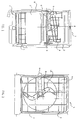
- FIG. 1 With reference to the figures, in particular to figure 1, with reference number 1 there is indicated as a whole a dishwashing machine of known type, comprising a box structure 2 defining its inside a washing chamber 3 wherein there are arranged two baskets 4 and 5 for loading the dishes.
- each basket a spraying organ for the washing liquid is arranged; more particularly the sprayer 7 is under the lower basket 5 and the sprayer 6 under the upper basket 4.
- the sprayers 6 and 7 rotate around a substantially vertical axis (but not necessarly perpendicular in respect of the base) and on a plane substantially parallel to the lying plane of the baskets (said axis and plane, for the sprayer 6, are indicated in figure 1 with letters A and B respectively) and are supplied in a known way.
- a tubular body 9 which connects the sprayer 6 to the water supply circuit 8 (shown only in part).
- FIG 2 there is shown the dishwashing machine realized according to a preferred solution of the present invention.
- an upper spraying organ is indicated with 15, having a non-straight principal axis.
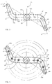
- substantially S-shaped as its principal axis D, there can be noted two portions having a substantially hemisimmetric shape 15a and 15b, each of them presenting a curved zone 16a and 16b.
- the sprayer 15 provides for apertures in correspondence of the two ends and such apertures, indicated with 17a and 17b, are arranged in a substantially radial way in respect of the rotating axis A, so as not to cause the thrust for the sprayer, that is obtained in a different manner.
- apertures 17a and 17b having a triangular shape
- the direction of such apertures 17a and 17b is choosen so as the related jets can reach far zones, which are external to the maximal circumference of the sprayer diameter.
- the apertures 17a and 17b are arranged on a same radial axis C, passing through the center of the sprayer.
- the other apertures shown in the figure with reference numbers 18, 19, 21, 22 and 23 are arranged in a non-simmetric way on the two portions of the sprayer 15, and so that in at least one of the two curved zones 16a and/or 16b there is present one of such apertures (in the specific case the aperture indicated with reference number 22).
- the operation of the dishwashing machine according to the present invention is as follows.
- the washing liquid enters the sprayer 15, passes through it and exits in the form of jets from the different apertures 17a, 18, 19, 21, 22, 23, 17b. Due to the particular shape of the sprayer 15, the rotation thrust is not obtained by means of jets (generally two, arranged at the ends of the arm), properly inclined.
- the thrust is determined by the fact that the water flow which passes inside the sprayer is forced to change the direction in correspondence of the two curved zones 16a and 16b.
- the thrust on the walls S and S' for the arm in respect of the axis A determines the rotation torque.
- the jets can therefore be straight or can be directed where they are needed, without particular restraints of inclination or positioning, as the rotation is obtained as described, in a different way.
- two homologous jets with the same type of holes can give rise to two jets of different type.
- the apertures can be realized so as the same zone is covered by two jets supplied in a different way.
- the apertures arranged proximate to the ends of the sprayer have a larger outlet than the other apertures: in this way an easier exit from the arm to the eventual solid residues not filtered is allowed, in order to limit the possible obstuctions to the extremities jets, which in general suffer more from this drawback.
- the described machine is preferably a dishwasher having a chamber with rectangular section but, as said, the example previously described must not be considered as limiting.
- the spraying device could have spraying apertures also on its lower side, for cooperating for the washing of the dishes contained in the lower basket or with the purpose of cleaning the machine filter (in the first case the further apertures will be on the lower side of the upper sprayer, while in the second case they will be on the lower side of the lower sprayer).
Landscapes
- Washing And Drying Of Tableware (AREA)
- Beverage Vending Machines With Cups, And Gas Or Electricity Vending Machines (AREA)
- Vending Machines For Individual Products (AREA)
Abstract
The present invention refers to a dishwashing machine (1) of the type comprising a washing chamber (3), at least one basket (4,5) for containing the dishes and at least one spraying organ (15), fed through a water supply circuit (8) and rotating around a substantially vertical axis.
The main feature of the described dishwashing machine (1) is that it provides for at least one spraying organ (15) having a non-straight axis.
Description
- The present invention refers to a dishwashing machine of the type comprising a washing chamber, at least one basket for containing the dishes and at least one spraying organ, fed through a water supply circuit and rotating around a substantially vertical axis.
- As it is known, dishwashing machines are provided with spraying organs, whose length is slightly minor than the shortest side of the section of the washing chamber which contains them.
- In this way the sprayer, or arm, can freely rotate on a substantially horizontal plane and the area of the washing chamber section which is not interested by the rotating movement is function of the plan of the same chamber; this area is minimal in case of squared plan.
- This embodiment has always involved the use of spraying organs with a substantially straight principal axis, having a plurality of apertures through which the water jets which sprinkle the dishes exit.
- It is also known that the improvement of the washing quality can be obtained just operating on the spraying organ, directly or indirectly. For example the Italian patent application nr. 67077A/89 describes a dishwashing machine, with a washing chamber having a rectangular section, provided with two spraying arms rotating according to two vertical axis, which are staggered in respect of the chamber plan, in order to minimize the areas not covered directly by the washing jets. By this solution, which can be implemented also in dishwashing machines of the traditional type, the area not covered by the spraying action of the rotating arms is reduced and the use of arms for dishwashing machine can be standardized; the improvement of the washing is in this case obtained by acting on the arrangement of the arms in the inside of the washing chamber.
- Another example of indirect action is contained in the US patent nr. 3876148, wherein the improvement of the washing is obtained by the addition of secondary arms which, by means of an epicyclic movement, allow the spraying holes to follow a non-repetitive path.
- Also in this case the area covered during the washing is increased, but there is a certain complexity of the spraying organ, as it must be equipped with an additional arm, whose rotation is indipendent in respect of the rotation of the principal arm.
- In order to improve the washing it is then possible to directly operate on the sprayer. For example the French utility model nr. 7828597 describes a rotating arm for dishwashers, which sprinkles jets with a great kinetic energy even in case of low speed rotation. According to the embodiment therein, this is allowed by the arm shape: the cross section of its body increases from the center towards the ends, while on the contrary the dimensions of the spraying holes decrease from the center of the arm towards its ends.
- By this solution, combined with the use of a water delivery having a minimum section, could be obtained a boost of the jets energy, determined by the centrifugal forces which act on the water quantity in the inside of the arm, and a better distribution of the water, due to the fact that the diameter of the holes decreases towards the ends. Other proposed solutions, which operate directly on the spraying organs, refer essentially to the holes dimensions and their arrangement on a rotating arm with a straight longitudinal development (for instance the English patent application nr. 2019204); others (for instance the German patent application nr. 3627813) propose sprayers with a non-symmetrical weights distribution.
- Anyway, also in these cases, independently of the section of the hydraulic circuit or the water delivery and of the shape of the water chamber, the improvement of the washing efficiency has been investigated by using spraying organs having a straight principal axis, by searching appropriate geometries of the spraying organs and/or the increase of the jets pressure.
- Furthermore, in this kind of spraying organs, the thrust for the rotation has always been obtained by means of inclined jets or outlets having thrust components in this sense.
- More particularly, the spraying organs of the known type generally provide two thrust jets, inclined and positioned at the ends of the sprayer, which exit two apertures, each of them arranged on one of the two portions of the same prayer.
- It is therefore clear that, in the case of obstruction of one of these apertures, the related jets do not operate again and the thrust is reduced to about 50%, and it is clear that the rotation speed is greatly influenced by the presence of foam in the washing liquid.
- Thus it is the object of the present invention to obviate to these drawbacks, by indicating a dishwashing machine which assures a good washing quality by means of a spraying organ which has thrust constancy, rotates at a low speed and has no restraints regarding the jets inclination; according to the present invention this improvement is not obtained by modifying the washing chamber structure or the section of the water delivery, but, the used water being the same, by means of a sprayer having a particular shape and due to the particular arrangement on it of the apertures for the washing liquid jets.
- These and other objects are achieved according to the present invention by means of a dishwashing machine, of the type comprising a washing chamber, at least one basket for containing the dishes and at least one spraying organ, fed through a water supply circuit and rotating around a substantially vertical axis, characterized in that it provides for at least one spraying organ having a non-straight principal axis.
- Further objects and advantages of the present invention will be clear from the following description, given as an explicative and non limiting example, and with reference to the annexed drawings, wherein:
- figure 1 is a schematic frontal view of a dishwashing machine with the door open;
- figure 2 is an upper plan view of a dishwashing machine according to the present invention:
- figure 3 is an upper view the spraying organ of a dishwashing machine realized according to the present invention;
- figure 4 shows the positions of the spraying apertures on the spraying organ of the preceding figure, by illustrating its operation during the rotating movement.
- With reference to the figures, in particular to figure 1, with
reference number 1 there is indicated as a whole a dishwashing machine of known type, comprising abox structure 2 defining its inside awashing chamber 3 wherein there are arranged twobaskets - Under each basket a spraying organ for the washing liquid is arranged; more particularly the
sprayer 7 is under thelower basket 5 and thesprayer 6 under theupper basket 4. - The
sprayers sprayer 6, are indicated in figure 1 with letters A and B respectively) and are supplied in a known way. In the specific case there is provided atubular body 9 which connects thesprayer 6 to the water supply circuit 8 (shown only in part). - In figure 2 there is shown the dishwashing machine realized according to a preferred solution of the present invention.
- In such figure, which uses the same reference numbers for the same elements of the preceding figure, an upper spraying organ is indicated with 15, having a non-straight principal axis.
- In the following figure 3 such a sprayer is illustrated in more detail, by means of an upper view.
- In particular in the spraying
organ 15, substantially S-shaped, as its principal axis D, there can be noted two portions having a substantiallyhemisimmetric shape curved zone - Near the center of the sprayer, on its upper side, faced to the basked destined to be sprinkled, there is a
mouth 20, through which the sprayer is supplied with the washing liquid. On the same side there are arranged in an appropriate way the apertures through which the washing liquid jets exit. - In particular, according to the invention, the
sprayer 15 provides for apertures in correspondence of the two ends and such apertures, indicated with 17a and 17b, are arranged in a substantially radial way in respect of the rotating axis A, so as not to cause the thrust for the sprayer, that is obtained in a different manner. - The direction of
such apertures apertures - The other apertures, shown in the figure with
reference numbers sprayer 15, and so that in at least one of the twocurved zones 16a and/or 16b there is present one of such apertures (in the specific case the aperture indicated with reference number 22). The operation of the dishwashing machine according to the present invention is as follows. - Through the
water supply circuit 8 and thetubular body 9 the washing liquid enters thesprayer 15, passes through it and exits in the form of jets from thedifferent apertures sprayer 15, the rotation thrust is not obtained by means of jets (generally two, arranged at the ends of the arm), properly inclined. - On the contrary, the thrust is determined by the fact that the water flow which passes inside the sprayer is forced to change the direction in correspondence of the two
curved zones - In this way it is determined a thrust of the water on the internal curved walls S, S' (marked with an outlining) of the sprayer. and so a variation in the motion quantity of the washing liquid which passes through such zones.
- The thrust on the walls S and S' for the arm in respect of the axis A determines the rotation torque.
- The jets can therefore be straight or can be directed where they are needed, without particular restraints of inclination or positioning, as the rotation is obtained as described, in a different way.
- In particular, for instance, two homologous jets with the same type of holes can give rise to two jets of different type.
- In fact, the possibility of positioning, due to the S-geometry, two outlet holes of liquid, supplied with components of different speed, (before and after the curves S or S') allows the same zone to be sprayed by two jets which have different inclinations.
- This concept can be better comprised by figure 4, which illustrates the arrangement of the apertures, and thus of the jets, on the spraying organ. This figure has the aim to practically simulate the operation of the spraying device during its rotating movement. There can be clearly noted the non-simmetrical disposition of the apertures, which assures a complete covering of the area sprinkled by the jets.
- By the fact that the latter do not have any restraints of inclination, the apertures can be realized so as the same zone is covered by two jets supplied in a different way.
- The apertures arranged proximate to the ends of the sprayer have a larger outlet than the other apertures: in this way an easier exit from the arm to the eventual solid residues not filtered is allowed, in order to limit the possible obstuctions to the extremities jets, which in general suffer more from this drawback.
- It has been verified in practice that the washing machine object of the present invention complies properly with the aims previously cited.
- From the given description the advantages of the present invention are clear.
- In particular they are represented:
- by the possibility of mantaining low the sprayer revolutions, due to a certain thrust constancy, so as to grant a less mechanical wear of the supports;
- by the better possibility of positioning the jets, by virtue of the more available length of the arm, in respect of the radius.
- by the reduction of the pressure losses in the case that foam is present in the washing liquid;
- by the fact that the sprayer thrust is not substantially reduced even in the case of obstruction of one of the jets;
- by the possibility of using apertures with no particular structures.
- The described machine is preferably a dishwasher having a chamber with rectangular section but, as said, the example previously described must not be considered as limiting.
- Many changes can be made to the described dishwasher, without departing from the novelty principles inherent in the inventive idea. For example the spraying device could have spraying apertures also on its lower side, for cooperating for the washing of the dishes contained in the lower basket or with the purpose of cleaning the machine filter (in the first case the further apertures will be on the lower side of the upper sprayer, while in the second case they will be on the lower side of the lower sprayer).
- However, it is obvious that many other changes can be made to the dishwasher object of the present invention, which could simply and advantageously be a dishwasher of small dimensions.
Claims (13)
- Dishwashing machine, in particular of small dimensions, of the type comprising a washing chamber, at least one basket for containing the dishes and at least one spraying organ, fed through a water supply circuit and rotating around a substantially vertical axis lying substantially in the center of the section of said washing chamber, characterized in that it provides for at least one spraying organ (15) having a non-straight principal axis (D).
- Dishwashing machine, according to the preceding claim, characterized in that the length longitudinal development of said spraying organ (15) with non-straight principal axis (D) is longer than the shortest side of the plan of said washing chamber (3).
- Dishwashing machine, according to at least one of the preceding claims, characterized in that the said spraying organ (15) has a shape comprising at least two curved portions (16a, 16b), in particular it is substantially S-shaped.
- Dishwashing machine, according to the preceding claim, characterized in that the two curved portions (16a, 16b) have a curving so that the thrust operated by the water flow which passes the spraying organ (15) its inside produces a variation of the motion quantity which causes the rotation of the spraying organ (15).
- Dishwashing machine, according to at least one of the preceding claims, characterized in that the said spraying organ (15) provides for spraying apertures (18, 19, 21, 22, 23), at least a first one of them (19) arranged in the zone reached by the washing liquid before arriving to the curved portion (16a) and a second one (18) in the zone after the curved portion (16a).
- Dishwashing machine, according to at least one of the preceding claims, characterized in that the said spraying organ (15) provides for at least one aperture (17a, 17b) in correspondence of at least one of its extremities.
- Dishwashing machine, according to the preceding claim, characterized in that the said spraying aperture (17a, 17b) in correspondence of at least one of the extremities has an area larger than the other spraying apertures (18, 19, 21, 22, 23) realized on the said spraying organ (15).
- Dishwashing machine, according to claims 6 and 7, characterized in that the said spraying aperture (17a, 17b) in correspondence of at least one of the extremities has a triangular shape.
- Dishwashing machine, according to claim 6, characterized in that the said spraying organ (15) provides for a spraying aperture (17a, 17b) in correspondence of each extremity.
- Dishwashing machine, according to claim 9, characterized in that said apertures (17a, 17b) in correspondence of each extremity are arranged on a same radial axis (C) passing through the rotation center of the spraying organ (15), so that the jet resulting from said apertures can be dimensioned in such a way which allows a covering which extends the area covered in the rotating movement of the spraying organ (15).
- Dishwashing machine, according to at least one of the preceding claims, characterized in that the said spraying apertures (18, 19, 21, 22, 23) are arranged in a non-symmetric way on the two portions (15a, 15b) of the said spraying organ (15).
- Dishwashing machine, according to the preceding claim, characterized in that the two portions (15a, 15b) present a different number of spraying apertures.
- Dishwashing machine, according to at least one of the preceding claims, characterized in that there are provided spraying apertures on the both sides of the said spraying organ (15).
Applications Claiming Priority (2)
| Application Number | Priority Date | Filing Date | Title |
|---|---|---|---|
| IT67668A IT1240721B (en) | 1990-09-06 | 1990-09-06 | DISHWASHER MACHINE PERFECTED |
| IT6766890 | 1990-09-06 |
Publications (1)
| Publication Number | Publication Date |
|---|---|
| EP0474127A1 true EP0474127A1 (en) | 1992-03-11 |
Family
ID=11304359
Family Applications (1)
| Application Number | Title | Priority Date | Filing Date |
|---|---|---|---|
| EP91114599A Withdrawn EP0474127A1 (en) | 1990-09-06 | 1991-08-30 | Improved dishwashing machine |
Country Status (2)
| Country | Link |
|---|---|
| EP (1) | EP0474127A1 (en) |
| IT (1) | IT1240721B (en) |
Cited By (6)
| Publication number | Priority date | Publication date | Assignee | Title |
|---|---|---|---|---|
| WO2005095057A1 (en) * | 2004-04-01 | 2005-10-13 | Airmatic Gesellschaft für Umwelt und Technik mbH | Cleaning installation |
| EP2052663A3 (en) * | 2007-10-23 | 2009-06-24 | Premark FEG L.L.C. | Low-water-consumption rinsing and/or washing device, and dishwashing machine featuring such a device |
| US20100051071A1 (en) * | 2008-09-04 | 2010-03-04 | Jackson Msc Llc | Spray arm |
| EP2679134A1 (en) * | 2012-06-25 | 2014-01-01 | Candy S.p.A. | An auxiliary spray device for dishwashers |
| EP3120747A1 (en) | 2015-07-21 | 2017-01-25 | Winterhalter Gastronom Gmbh | Washing system for a dishwasher, and dishwasher with such a washing system |
| EP4252611A1 (en) * | 2022-03-31 | 2023-10-04 | D&P S.r.l. | Dishwashing machine |
Citations (8)
| Publication number | Priority date | Publication date | Assignee | Title |
|---|---|---|---|---|
| US1908617A (en) * | 1930-06-28 | 1933-05-09 | Nat Automatic Dishwasher Co Lt | Dishwasher |
| GB633496A (en) * | 1947-04-28 | 1949-12-19 | Electrolux Ab | Improvements in or relating to dish washing machines |
| GB833434A (en) * | 1957-08-21 | 1960-04-27 | Sven Gustaf Nord | Dishwashing apparatus |
| US3285779A (en) * | 1964-11-17 | 1966-11-15 | King Fifth Wheel Company | Dishwashing apparatus |
| DE1628547A1 (en) * | 1966-11-29 | 1970-10-22 | Constructa Werke Gmbh | Spray arm for a dishwasher |
| WO1983001186A1 (en) * | 1981-10-02 | 1983-04-14 | Eriksson, Gunnar, Gilbert | A spray nozzle |
| US4418868A (en) * | 1981-05-29 | 1983-12-06 | Whirlpool Corporation | Dishwasher upper spray arm |
| SU1294339A1 (en) * | 1985-01-04 | 1987-03-07 | Всесоюзный Научно-Исследовательский Экспериментально-Конструкторский Институт Электробытовых Машин И Приборов | Sprayer for dish washer |
-
1990
- 1990-09-06 IT IT67668A patent/IT1240721B/en active IP Right Grant
-
1991
- 1991-08-30 EP EP91114599A patent/EP0474127A1/en not_active Withdrawn
Patent Citations (8)
| Publication number | Priority date | Publication date | Assignee | Title |
|---|---|---|---|---|
| US1908617A (en) * | 1930-06-28 | 1933-05-09 | Nat Automatic Dishwasher Co Lt | Dishwasher |
| GB633496A (en) * | 1947-04-28 | 1949-12-19 | Electrolux Ab | Improvements in or relating to dish washing machines |
| GB833434A (en) * | 1957-08-21 | 1960-04-27 | Sven Gustaf Nord | Dishwashing apparatus |
| US3285779A (en) * | 1964-11-17 | 1966-11-15 | King Fifth Wheel Company | Dishwashing apparatus |
| DE1628547A1 (en) * | 1966-11-29 | 1970-10-22 | Constructa Werke Gmbh | Spray arm for a dishwasher |
| US4418868A (en) * | 1981-05-29 | 1983-12-06 | Whirlpool Corporation | Dishwasher upper spray arm |
| WO1983001186A1 (en) * | 1981-10-02 | 1983-04-14 | Eriksson, Gunnar, Gilbert | A spray nozzle |
| SU1294339A1 (en) * | 1985-01-04 | 1987-03-07 | Всесоюзный Научно-Исследовательский Экспериментально-Конструкторский Институт Электробытовых Машин И Приборов | Sprayer for dish washer |
Non-Patent Citations (1)
| Title |
|---|
| SOVIET PATENTS ABSTRACTS Section PQ, Week 8739, 7 October 1987 Derwent Publications Ltd., London, GB; Class P28, AN 87-276353/39 & SU-A-1 294 339 (ELECTR HOUSE MACHIN) 4 January 1985 * |
Cited By (9)
| Publication number | Priority date | Publication date | Assignee | Title |
|---|---|---|---|---|
| WO2005095057A1 (en) * | 2004-04-01 | 2005-10-13 | Airmatic Gesellschaft für Umwelt und Technik mbH | Cleaning installation |
| EP2052663A3 (en) * | 2007-10-23 | 2009-06-24 | Premark FEG L.L.C. | Low-water-consumption rinsing and/or washing device, and dishwashing machine featuring such a device |
| US20100051071A1 (en) * | 2008-09-04 | 2010-03-04 | Jackson Msc Llc | Spray arm |
| US8333207B2 (en) * | 2008-09-04 | 2012-12-18 | Jackson Msc Llc | Spray arm for directing spray in a warewashing machine |
| EP2679134A1 (en) * | 2012-06-25 | 2014-01-01 | Candy S.p.A. | An auxiliary spray device for dishwashers |
| EP3120747A1 (en) | 2015-07-21 | 2017-01-25 | Winterhalter Gastronom Gmbh | Washing system for a dishwasher, and dishwasher with such a washing system |
| DE102015111811A1 (en) * | 2015-07-21 | 2017-01-26 | Winterhalter Gastronom Gmbh | Washing system for a dishwasher, and dishwasher with such a washing system |
| DE102015111811B4 (en) | 2015-07-21 | 2017-02-09 | Winterhalter Gastronom Gmbh | Washing system for a dishwasher, and dishwasher with such a washing system |
| EP4252611A1 (en) * | 2022-03-31 | 2023-10-04 | D&P S.r.l. | Dishwashing machine |
Also Published As
| Publication number | Publication date |
|---|---|
| IT1240721B (en) | 1993-12-17 |
| IT9067668A1 (en) | 1992-03-06 |
| IT9067668A0 (en) | 1990-09-06 |
Similar Documents
| Publication | Publication Date | Title |
|---|---|---|
| US5333631A (en) | Cleaning wash-arm for dishwashing filter | |
| EP1847207B1 (en) | Wash/rinse system for a drawer-type dishwasher | |
| US3176697A (en) | Apparatus to control the action of and to distribute washing fluid in a dishwashing machine | |
| US2154559A (en) | Dishwashing machine | |
| US4509687A (en) | Multiple spray distribution system for a domestic dishwasher | |
| DE102005026558B3 (en) | Method for providing a pulsed wash spray in a domestic dish washing machine has a rotary member in the spray arms which opens and closes the liquid to the spray nozzles | |
| US3051184A (en) | Apparatus for washing articles | |
| US3348775A (en) | Reaction jet spray arm for dishwashers having simultaneous rotation about perpendicular axis | |
| GB2225224A (en) | Dishwashing machine with filter cleaning arrangement | |
| US3779258A (en) | Rotating silverware basket for dishwasher | |
| US2501887A (en) | Dishwasher | |
| CN108185967A (en) | Clean basket and cleaning device | |
| EP0474127A1 (en) | Improved dishwashing machine | |
| CN108135434A (en) | Dish-washing machine including distributor | |
| EP1090579B1 (en) | Revolving sprinkling assembly for dishwasher provided with a device for horizontal shift | |
| EP1510168B1 (en) | Wash arm arrangement for a dishwasher | |
| US3134386A (en) | Washing machine with selectively variable washing action | |
| US5433228A (en) | Self-cleaning bearing flange for dishwasher spray arm | |
| JP2782943B2 (en) | Dishwasher | |
| EP0772994A1 (en) | Dishwashing machine with improved hydraulic circuit | |
| CN111328269B (en) | Spray arm assembly of dish washer | |
| KR20060013790A (en) | A dish washer equipped with concentrating injection function | |
| JP2600447B2 (en) | Dishwasher | |
| CN110507266A (en) | A kind of totally enclosed type intelligent machine for stir-frying dishes cleans a pot cleaning system | |
| EP0321025A2 (en) | Hydraulic-motor driven rotary spray-arm device for dish-washing machines |
Legal Events
| Date | Code | Title | Description |
|---|---|---|---|
| PUAI | Public reference made under article 153(3) epc to a published international application that has entered the european phase |
Free format text: ORIGINAL CODE: 0009012 |
|
| AK | Designated contracting states |
Kind code of ref document: A1 Designated state(s): DE ES FR GB |
|
| STAA | Information on the status of an ep patent application or granted ep patent |
Free format text: STATUS: THE APPLICATION IS DEEMED TO BE WITHDRAWN |
|
| 18D | Application deemed to be withdrawn |
Effective date: 19920912 |