EP0474029B1 - Omnidirectional modular siren - Google Patents
Omnidirectional modular siren Download PDFInfo
- Publication number
- EP0474029B1 EP0474029B1 EP91113971A EP91113971A EP0474029B1 EP 0474029 B1 EP0474029 B1 EP 0474029B1 EP 91113971 A EP91113971 A EP 91113971A EP 91113971 A EP91113971 A EP 91113971A EP 0474029 B1 EP0474029 B1 EP 0474029B1
- Authority
- EP
- European Patent Office
- Prior art keywords
- siren
- modules
- omnidirectional
- active
- module
- Prior art date
- Legal status (The legal status is an assumption and is not a legal conclusion. Google has not performed a legal analysis and makes no representation as to the accuracy of the status listed.)
- Expired - Lifetime
Links
Images

Classifications
-
- G—PHYSICS
- G10—MUSICAL INSTRUMENTS; ACOUSTICS
- G10K—SOUND-PRODUCING DEVICES; METHODS OR DEVICES FOR PROTECTING AGAINST, OR FOR DAMPING, NOISE OR OTHER ACOUSTIC WAVES IN GENERAL; ACOUSTICS NOT OTHERWISE PROVIDED FOR
- G10K9/00—Devices in which sound is produced by vibrating a diaphragm or analogous element, e.g. fog horns, vehicle hooters or buzzers
- G10K9/18—Details, e.g. bulbs, pumps, pistons, switches or casings
- G10K9/22—Mountings; Casings
-
- G—PHYSICS
- G10—MUSICAL INSTRUMENTS; ACOUSTICS
- G10K—SOUND-PRODUCING DEVICES; METHODS OR DEVICES FOR PROTECTING AGAINST, OR FOR DAMPING, NOISE OR OTHER ACOUSTIC WAVES IN GENERAL; ACOUSTICS NOT OTHERWISE PROVIDED FOR
- G10K11/00—Methods or devices for transmitting, conducting or directing sound in general; Methods or devices for protecting against, or for damping, noise or other acoustic waves in general
- G10K11/02—Mechanical acoustic impedances; Impedance matching, e.g. by horns; Acoustic resonators
- G10K11/025—Mechanical acoustic impedances; Impedance matching, e.g. by horns; Acoustic resonators horns for impedance matching
Definitions
- the present invention relates generally to outdoor warning sirens and, more particularly, to an omnidirectional siren, comprising:
- each of the active modules comprises a housing including a male disc-shaped portion with an integrally formed hub portion forming crown-like manifold means consisting of six presumably separate sound channels arranged about the axis of the central column and being slightly inclined outwardly like the peaks or prongs of a crown.
- transducers are attached to the outer ends of said prongs.
- US-A-4,908,601 discloses an omnidirectional modular siren having a plurality of stacked disc-shaped modules with each active modul having a horn assembly attached to its lower surface for emitting sound waves.
- the known siren has a single driver per active modul which driver is mounted vertically within the modul and directed downward toward the horn assembly.
- the stack of modules is supported by a plurality of exteriorly mounted aluminum cast segments and a plurality of spacer bolts.
- the use of only one single transducer typically requires that the same be very powerful and correspondingly expensive.
- WO-A-8 703 994 discloses an omnidirectional siren comprising a a star-like configuration of transducer/horn assemblies.
- the known electronic outdoor warning siren does not have a modular design including a plurality of stacked hollow modules.
- GB-A-1 108 521 discloses an omnidirectional modular siren of a design generally similar to the design of the siren according to US-A-4 908 601.
- omnidirectional outdoor warning sirens have been available which consist of multiple horns mounted in back-to-back circular arrays. These sirens exhibit lobing problems in their coverage patterns, however, due to cancellation and/or addition of sound waves emanating from the multiple sources. Consequently, rotation of such arrays is necessary to ensure total area coverage.
- omnidirectional modular sirens have become available through companies such as Whelen Technologies, Inc., and Kockum Sonis. Those sirens consist of a plurality of stacked, disc-shaped modules, each active module having an orifice in either its lower or upper surface through which sound waves - generated by an interiorly mounted compression driver/horn assembly - pass and then spread out omnidirectionally.
- Whelen's sirens have a single driver/horn assembly per active module, with each driver/horn assembly mounted vertically within a module and directed toward an upper orifice. Since only one driver is used in each module by Whelen, each driver must be very powerful (typically 400 watts) and is, therefore, quite expensive.
- Kockum Sonics a Swedish company, manufactures sirens having 1-3 drivers per active module, but the specific arrangement of the drivers and their respective horn assemblies within the modules is presently unkown to applicant.
- the vertical stack of modules making up a Whelen siren is coupled together by means of an assembly consisting of a plurality of exteriorly mounted, aluminum cast spacers and annular members (as shwon in U.S. Design Patent 305,660) and the Kockum Sonics modules are coupled by means of a plurality of tie rods and spacers.
- Access to a driver housed within a module, such as for repair or replacement, is possible in either a Whelen or Kockum Sonics siren only by disassembling the module, thus requiring disassembly of all or part of the coupling assembly. Such disassembly, of course, is quite time consuming and costly.
- This object according to the present invention is accomplished by means of an omnidirectional siren of the type indicated at the outset, which siren is characterized in that the horn means comprises:
- an omnidirectional siren having a plurality of hollow modules supported in vertical alignment on a single, central pole.
- Active modules each enclose a plurality of audio transducers (i.e., compression drivers) and a horn mechanism which guides sound waves from the drivers to an outlet in the lower surface of the module.
- the drivers are positioned peripherally within each module so that they can be easily accessed for repair or replacement through slots in the peripheral surface of the module.
- the inventive siren includes a plurality of housing modules 11 -- preferably made of aluminum -- mounted in spaced-apart vertical alignment on a single, central support pole 12.
- the embodiment of the inventive siren 10 shown in FIG. 1 has five such modules 11, but it should be noted that the siren can have more than five modules or as few as two, depending on its specific intended use. So that it can receive and provide a passage for electrical wires 13 and yet, on its own, provide adequate support for the plurality of modules, the support pole 12 is preferably a hollow pipe made of steel (or some other metal) having an outer diameter of approximately four inches.
- a first bracket 14 having an annular flange 15 is connected to the lower end of the support pole 12, thereby providing means for attaching the siren to a supporting structure.
- a second bracket 16 having a corresponding annular flange 17 is coupled to an underlying support structure 18, such as a wooden pole, and the siren is connected to the support structure by bolting or otherwise fastening the two annular flanges 15, 17 to one another.
- Each of the modules 11 consists of an upper, female dish-shaped portion 19 and a lower, male dish-shaped portion 20 which are coupled in edgewise mating relation and fastened together by screws or rivets 21 to form a hollow cavity (see Fig. 2).
- Apertures 22, 23 are provided in the top and bottom surfaces of each module, permitting the support pole 12 to extend therethrough.
- the aperture 22a in the top surface of the upper module is quite small, of course, so as to keep out dust and precipitation and yet provide a through-hole for a lifting ring 24 which is connected by means of a bracket 25 and bolts 26 to the support pole 12.
- All of the modules -- except the bottom one in the vertical stack -- are active, containing electrically-powered sound wave producing elements, as shown in FIGS. 2 and 3.
- the lower apertures 23 in these active modules are larger in diameter than the diameter of the support pole 12, thereby providing an annular port for emission of sound waves from the module.
- each active module has a horn mechanism 27 which is configured so as to support a plurality of audio transducers (i.e., compression drivers) 28 -- preferably four standard 100 watt drivers -- near the peripheral surface 29 of the module. More specifically, the horn mechanism 27 comprises a central manifold 30 and a plurality of waveguide horns 31, coupled together in a hub-and-spoke type arrangement (see FIG. 3).
- a plurality of audio transducers i.e., compression drivers
- Each of the waveguide horns 31 has a female threaded section 32 at its outwardly-facing end for removably receiving the male threaded portion 33 of a compression driver 28.
- This type of threaded connection between the waveguide horns 31 and drivers 28 permits easy removal of the peripherally-positioned drivers from the module 11 through peripheral access slots 34 (normally covered by removable plates 34a), thereby greatly reducing the time and expense required to service or replace the drivers.
- the other end of each waveguide horn 31 terminates in an annular flange 35, by which the waveguide horn 31 can be connected -- such as with bolts 36 -- to the manifold 30.
- each waveguide horn 31 further has a pair of vanes 37 extending therefrom, which provide internal support to prevent deformation of the surfaces of the module 11.
- vanes can, of course, take any of a variety of configurations. Also, as can be readily appreciated by those skilled in the art, it is preferred acoustically that the internal area of each of the waveguide horns 31 increases hyperbolically in the direction of sound wave travel.
- the manifold 30 in each active module includes a central wall 38 which forms an annular longitudinal passage 39 through which the support pole 12 slideably extends.
- Bolts or other appropriate fasteners (not shown) are interposed through transverse holes 40 (see FIG. 6) in the wall 38 of the manifold 30 and through aligned holes (not shown) in the support pole 12 to secure the manifold to the pole.
- the lower portion 20 of a module 11 is rigidly secured to the bottom of each manifold 30 by means of bolts 41 extending through receiving holes 42 in a lower flange 43 of the manifold and aligned holes (not shown) in the module surface.
- each manifold 30 further includes a plurality of waveguide passages 44, preferably having one such passage for each compression driver (i.e., transducer) 28 mounted in the module 11.
- These waveguide passages 44 are each defined by a portion of the central wall 38 of the manifold, a reflecting surface 45, side walls 46 and an exterior wall 47.
- Sound waves generated by a transducer 28 and propagated through an associated horn waveguide 31 are introduced into a manifold waveguide passage 44 through an inlet port 48 in the exterior wall 47, reflect downwardly off the surface 45 (which is preferably angled at about 45° to the incident sound waves) and exit from the waveguide passage 44 through a port 49 at the bottom of the manifold, propagating through the passage generally in the direction of the arrow in FIG. 2.
- the four waveguide passages 44 in the manifold 30 all expand hyperbolically in the direction of sound wave travel and terminate adjacent to one another. Indeed, as shown in FIG. 5, adjacent waveguide passages are separated only by a thin wall 50 at the bottom of the manifold, thus defining the substantially annular output port 49 which corresponds with the annular sound wave emission port 23 of a module 11.
- the annular sound wave emission port 23 should typically be covered with a mesh screen (not shown) to prevent debris from getting inside and blocking the manifold waveguides 44.
- Sound waves emanating from the annular port 23 reflect laterally off a reflecting member 51 and spread out omnidirectionally.
- the reflecting members 51 are preferably conical in shape and comprise integral protuberances of the upper portions 19 of the modules 11. Spreading of the resulting omnidirectional sound wavefronts is acoustically enhanced by utilization of modules 11 which have hyperbolic outer surfaces (i.e., hyperbolic upper and lower portions 19, 20).
- this invention provides an improved omnidirectional siren having only a single, central support for a plurality of modules. Audio transducers are mounted peripherally within the modules and are, therefore, easy and inexpensive to service or replace through peripheral access slots in the modules.
Landscapes
- Physics & Mathematics (AREA)
- Engineering & Computer Science (AREA)
- Acoustics & Sound (AREA)
- Multimedia (AREA)
- Apparatuses For Generation Of Mechanical Vibrations (AREA)
- Measurement Of Velocity Or Position Using Acoustic Or Ultrasonic Waves (AREA)
Description
- The present invention relates generally to outdoor warning sirens and, more particularly, to an omnidirectional siren, comprising:
- a support column;
- a plurality of hollow modules supported in spaced-apart, vertical alignment on the support column, each module having apertures in both its top and bottom surfaces through which the support column extends;
- each but one of the modules being active due to enclosure of a plurality of sound wave producing transducers, with one of the apertures in each of the active modules being larger in diameter than the support column extending therethrough, thereby providing an annular port for emission of sound waves from the module; and
- horn means in each active module for guiding sound waves from the enclosed plurality of transducers to the annular sound wave emission port.
- An omnidirectional modular siren of this type is known from EP-A-0 252 337 which discloses an omnidirectional siren, wherein each of the active modules comprises a housing including a male disc-shaped portion with an integrally formed hub portion forming crown-like manifold means consisting of six presumably separate sound channels arranged about the axis of the central column and being slightly inclined outwardly like the peaks or prongs of a crown.
- Further, the transducers are attached to the outer ends of said prongs.
- Further, US-A-4,908,601 discloses an omnidirectional modular siren having a plurality of stacked disc-shaped modules with each active modul having a horn assembly attached to its lower surface for emitting sound waves. The known siren has a single driver per active modul which driver is mounted vertically within the modul and directed downward toward the horn assembly. The stack of modules is supported by a plurality of exteriorly mounted aluminum cast segments and a plurality of spacer bolts. The use of only one single transducer typically requires that the same be very powerful and correspondingly expensive.
- Further, WO-A-8 703 994 discloses an omnidirectional siren comprising a a star-like configuration of transducer/horn assemblies. The known electronic outdoor warning siren does not have a modular design including a plurality of stacked hollow modules.
- Further, GB-A-1 108 521 discloses an omnidirectional modular siren of a design generally similar to the design of the siren according to US-A-4 908 601.
- Generally for years, omnidirectional outdoor warning sirens have been available which consist of multiple horns mounted in back-to-back circular arrays. These sirens exhibit lobing problems in their coverage patterns, however, due to cancellation and/or addition of sound waves emanating from the multiple sources. Consequently, rotation of such arrays is necessary to ensure total area coverage.
- More recently, omnidirectional modular sirens have become available through companies such as Whelen Technologies, Inc., and Kockum Sonis. Those sirens consist of a plurality of stacked, disc-shaped modules, each active module having an orifice in either its lower or upper surface through which sound waves - generated by an interiorly mounted compression driver/horn assembly - pass and then spread out omnidirectionally. Whelen's sirens have a single driver/horn assembly per active module, with each driver/horn assembly mounted vertically within a module and directed toward an upper orifice. Since only one driver is used in each module by Whelen, each driver must be very powerful (typically 400 watts) and is, therefore, quite expensive. Kockum Sonics, a Swedish company, manufactures sirens having 1-3 drivers per active module, but the specific arrangement of the drivers and their respective horn assemblies within the modules is presently unkown to applicant.
- The vertical stack of modules making up a Whelen siren is coupled together by means of an assembly consisting of a plurality of exteriorly mounted, aluminum cast spacers and annular members (as shwon in U.S. Design Patent 305,660) and the Kockum Sonics modules are coupled by means of a plurality of tie rods and spacers. Access to a driver housed within a module, such as for repair or replacement, is possible in either a Whelen or Kockum Sonics siren only by disassembling the module, thus requiring disassembly of all or part of the coupling assembly. Such disassembly, of course, is quite time consuming and costly.
- It is an object of the present invention to provide an improved modular siren which is easy and inexpensive to service.
- This object according to the present invention is accomplished by means of an omnidirectional siren of the type indicated at the outset, which siren is characterized in that the horn means comprises:
- a central manifold having a longitudinal passage through which the support column extends and a plurality of waveguide passages through which sound waves travel, wherein each waveguide passage includes a separate input port for receiving sound waves from a transducer and the plurality of waveguide passages terminate adjacent to one another and form an annular output port which cooperates with the annular sound wave emission port of the module and
- a plurality of waveguide horns which couple the plurality of transducers to the input ports of the manifold waveguide passages with said central manifold and said plurality of waveguide horns, coupled together in a hub-and-spoke type arrangement; and
- that the transducers are mounted peripherally within the active modules so as to be accessible through access slots in the peripheral surfaces of the modules.
- It is an advantage of the present invention that it provides an improved modular siren having drivers positioned peripherally within each active module adjacent to covered access openings in the module wall.
- It is a further advantage of this invention that it provides a modular siren having a plurality of low power drivers in each module.
- It is another advantage of this invention that it provides a modular siren having only a single, central support for the modules.
- In accordance with a preferred embodiment of the present invention, there is provided an omnidirectional siren having a plurality of hollow modules supported in vertical alignment on a single, central pole. Active modules each enclose a plurality of audio transducers (i.e., compression drivers) and a horn mechanism which guides sound waves from the drivers to an outlet in the lower surface of the module. The drivers are positioned peripherally within each module so that they can be easily accessed for repair or replacement through slots in the peripheral surface of the module.
- Other objects and advantages of the invention will be apparent from the following detailed description.
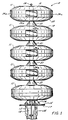
- Figure 1 is a side plan view of a modular siren embodying the present invention;
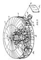
- Figure 2 is a cross-sectional view of the uppermost module in the modular siren of Figure 1;
- Figure 3 is a partially sectional perspective view of the driver/horn assembly of the module shown in Figure 2;
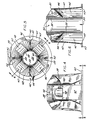
- Figure 4 is a side plan view of the horn manifold of the present invention;
- Figure 5 is a bottom plan view of the horn manifold taken along the line 5-5 in Figure 4; and
- Figure 6 is a cross-sectional view of the horn manifold taken along the line 6-6 in Figure 5.
- While the invention will be described in connection with particular preferred embodiments, it will be understood that it is not intended to limit the invention to those particular embodiments. On the contrary, it is intended to cover all alternatives, modifications and equivalents as may be included within the spirit and scope of the invention as defined by the appended claims.
- Turning now to the drawings and referring first to FIG. 1, there is shown an omnidirectional
modular siren 10 constructed in accordance with the invention. The inventive siren includes a plurality of housing modules 11 -- preferably made of aluminum -- mounted in spaced-apart vertical alignment on a single,central support pole 12. The embodiment of theinventive siren 10 shown in FIG. 1 has five such modules 11, but it should be noted that the siren can have more than five modules or as few as two, depending on its specific intended use. So that it can receive and provide a passage forelectrical wires 13 and yet, on its own, provide adequate support for the plurality of modules, thesupport pole 12 is preferably a hollow pipe made of steel (or some other metal) having an outer diameter of approximately four inches. - A first bracket 14 having an
annular flange 15 is connected to the lower end of thesupport pole 12, thereby providing means for attaching the siren to a supporting structure. As shown in FIG. 1, asecond bracket 16 having a corresponding annular flange 17 is coupled to anunderlying support structure 18, such as a wooden pole, and the siren is connected to the support structure by bolting or otherwise fastening the twoannular flanges 15, 17 to one another. - Each of the modules 11 consists of an upper, female dish-
shaped portion 19 and a lower, male dish-shaped portion 20 which are coupled in edgewise mating relation and fastened together by screws or rivets 21 to form a hollow cavity (see Fig. 2).Apertures support pole 12 to extend therethrough. Theaperture 22a in the top surface of the upper module is quite small, of course, so as to keep out dust and precipitation and yet provide a through-hole for alifting ring 24 which is connected by means of abracket 25 and bolts 26 to thesupport pole 12. - All of the modules -- except the bottom one in the vertical stack -- are active, containing electrically-powered sound wave producing elements, as shown in FIGS. 2 and 3. The
lower apertures 23 in these active modules are larger in diameter than the diameter of thesupport pole 12, thereby providing an annular port for emission of sound waves from the module. - In accordance with one important aspect of the present invention, each active module has a
horn mechanism 27 which is configured so as to support a plurality of audio transducers (i.e., compression drivers) 28 -- preferably four standard 100 watt drivers -- near theperipheral surface 29 of the module. More specifically, thehorn mechanism 27 comprises acentral manifold 30 and a plurality ofwaveguide horns 31, coupled together in a hub-and-spoke type arrangement (see FIG. 3). - Each of the
waveguide horns 31 has a female threaded section 32 at its outwardly-facing end for removably receiving the male threaded portion 33 of acompression driver 28. This type of threaded connection between thewaveguide horns 31 anddrivers 28 permits easy removal of the peripherally-positioned drivers from the module 11 through peripheral access slots 34 (normally covered byremovable plates 34a), thereby greatly reducing the time and expense required to service or replace the drivers. The other end of eachwaveguide horn 31 terminates in an annular flange 35, by which thewaveguide horn 31 can be connected -- such as withbolts 36 -- to themanifold 30. - In the preferred embodiment of the inventive siren, each
waveguide horn 31 further has a pair ofvanes 37 extending therefrom, which provide internal support to prevent deformation of the surfaces of the module 11. These vanes can, of course, take any of a variety of configurations. Also, as can be readily appreciated by those skilled in the art, it is preferred acoustically that the internal area of each of thewaveguide horns 31 increases hyperbolically in the direction of sound wave travel. - The
manifold 30 in each active module includes acentral wall 38 which forms an annularlongitudinal passage 39 through which thesupport pole 12 slideably extends. Bolts or other appropriate fasteners (not shown) are interposed through transverse holes 40 (see FIG. 6) in thewall 38 of the manifold 30 and through aligned holes (not shown) in thesupport pole 12 to secure the manifold to the pole. Similarly, thelower portion 20 of a module 11 is rigidly secured to the bottom of each manifold 30 by means ofbolts 41 extending through receivingholes 42 in alower flange 43 of the manifold and aligned holes (not shown) in the module surface. - As shown in FIGS. 4-6, each manifold 30 further includes a plurality of
waveguide passages 44, preferably having one such passage for each compression driver (i.e., transducer) 28 mounted in the module 11. Thesewaveguide passages 44 are each defined by a portion of thecentral wall 38 of the manifold, a reflectingsurface 45,side walls 46 and anexterior wall 47. Sound waves generated by atransducer 28 and propagated through an associatedhorn waveguide 31 are introduced into amanifold waveguide passage 44 through an inlet port 48 in theexterior wall 47, reflect downwardly off the surface 45 (which is preferably angled at about 45° to the incident sound waves) and exit from thewaveguide passage 44 through aport 49 at the bottom of the manifold, propagating through the passage generally in the direction of the arrow in FIG. 2. - In the preferred embodiment, the four
waveguide passages 44 in the manifold 30 all expand hyperbolically in the direction of sound wave travel and terminate adjacent to one another. Indeed, as shown in FIG. 5, adjacent waveguide passages are separated only by athin wall 50 at the bottom of the manifold, thus defining the substantiallyannular output port 49 which corresponds with the annular soundwave emission port 23 of a module 11. - The annular sound
wave emission port 23 should typically be covered with a mesh screen (not shown) to prevent debris from getting inside and blocking themanifold waveguides 44. - Sound waves emanating from the
annular port 23 reflect laterally off a reflectingmember 51 and spread out omnidirectionally. The reflectingmembers 51 are preferably conical in shape and comprise integral protuberances of theupper portions 19 of the modules 11. Spreading of the resulting omnidirectional sound wavefronts is acoustically enhanced by utilization of modules 11 which have hyperbolic outer surfaces (i.e., hyperbolic upper andlower portions 19, 20). - As can be seen from the foregoing detailed description, this invention provides an improved omnidirectional siren having only a single, central support for a plurality of modules. Audio transducers are mounted peripherally within the modules and are, therefore, easy and inexpensive to service or replace through peripheral access slots in the modules.
Claims (13)
- An omnidirectional siren (10), comprising:a support column (12);a plurality of hollow modules (11) supported in spaced-apart, vertical alignment on the support column (12), each module (11) having apertures (22, 22a, 23) in both its top and bottom surfaces through which the support column (12) extends;each but one of the modules (11) being active due to enclosure of a plurality of sound wave producing transducers (28), with one (23) of the apertures in each of the active modules (11) being larger in diameter than the support column (12) extending therethrough, thereby providing an annular port (23) for emission of sound waves from the module (11); andhorn means (27) in each active module (11) for guiding sound waves from the enclosed plurality of transducers (28) to the annular sound wave emission port (23), characterized in that the horn means (27) comprises:a central manifold (30) having a longitudinal passage (39) through which the support column (12) extends and a plurality of waveguide passages (44) through which sound waves travel, wherein each waveguide passage (44) includes a separate input port (48) for receiving sound waves from a transducer (28) and the plurality of waveguide passages (44) terminate adjacent to one another and form an annular output port (49) which cooperates with the annular sound wave emission port (23) of the module (11); anda plurality of waveguide horns (31) which couple the plurality of transducers (28) to the input ports (48) of the manifold waveguide passages (44) with said central manifold (30) and said plurality of waveguide horns (31), coupled together in a hub-and-spoke type arrangement; andthat the transducers (28) are mounted peripherally within the active modules (11) so as to be accessible through access slots (34) in the peripheral surfaces (29) of the modules (11).
- The omnidirectional siren of claim 1, further comprising reflecting members (51) positioned on the support column (12) between adjacent modules (11) so as to omnidirectionally reflect sound waves emanating from the annular sound wave emission ports.
- The omnidirectional siren of claim 2, wherein said reflecting members (51) are substantially conical.
- The omnidirectional siren of claim 2, in which each module (11) has upper and lower dish-shaped portions (19, 20) coupled in edgewise mating relation, wherein the apertures (22, 23) forming the annular sound wave emission ports (49) are located in the lower portions (20) of the modules (11) and the reflecting members (51) are integral protuberances of the upper portions (19) of the modules (11).
- The omnidirectional siren of claim 1, wherein each active module (11) encloses four transducers (28).
- The omnidirectional siren of claim 5, wherein said transducers (28) are 100 watt transducers.
- The omnidirectional siren of claim 1, wherein the waveguide horns (31) and the manifold waveguides (44) all expand hyperbolically in the direction of sound wave travel.
- The omnidirectional siren of claim 4, wherein the upper and lower dish-shaped portions (19, 20) of the module (11) each has a hyperbolic surface.
- The omnidirectional siren of claim 1 having two modules (11), only one of which is active.
- The omnidirectional siren of claim 1 having three modules (11), two of which are active.
- The omnidirectional siren of claim 1 having four modules (11), three of which are active.
- The omnidirectional siren of claim 1 having five modules (11), four of which are active.
- The omnidirectional siren of claim 1 having seven modules (11), six of which are active.
Applications Claiming Priority (2)
| Application Number | Priority Date | Filing Date | Title |
|---|---|---|---|
| US579307 | 1984-02-13 | ||
| US07/579,307 US5146508A (en) | 1990-09-07 | 1990-09-07 | Omindirectional modular siren |
Publications (3)
| Publication Number | Publication Date |
|---|---|
| EP0474029A2 EP0474029A2 (en) | 1992-03-11 |
| EP0474029A3 EP0474029A3 (en) | 1992-12-02 |
| EP0474029B1 true EP0474029B1 (en) | 1997-06-04 |
Family
ID=24316371
Family Applications (1)
| Application Number | Title | Priority Date | Filing Date |
|---|---|---|---|
| EP91113971A Expired - Lifetime EP0474029B1 (en) | 1990-09-07 | 1991-08-21 | Omnidirectional modular siren |
Country Status (3)
| Country | Link |
|---|---|
| US (1) | US5146508A (en) |
| EP (1) | EP0474029B1 (en) |
| DE (1) | DE69126387T2 (en) |
Families Citing this family (27)
| Publication number | Priority date | Publication date | Assignee | Title |
|---|---|---|---|---|
| US10110993B1 (en) * | 2015-12-02 | 2018-10-23 | Ati Systems, Inc. | High-power electronic omnidirectional speaker array |
| US5321388A (en) * | 1992-03-16 | 1994-06-14 | American Signal Corporation | High efficiency phase and amplitude matched multiple horn electronic siren |
| TWM246931U (en) * | 2003-12-03 | 2004-10-11 | Sekaku Electron Industry Co Lt | Sound box and its stacked assembling structure |
| US7360499B1 (en) | 2004-12-21 | 2008-04-22 | Essi Corporation | Helmholtz resonator type marine signal |
| US7621369B2 (en) * | 2006-06-16 | 2009-11-24 | Graber Curtis E | Acoustic energy projection system |
| DE102007019450A1 (en) | 2007-04-10 | 2008-10-16 | Michael Schwahn | Omnidirectional radiating and receiving horn has two volume bodies mounted one above other at distance from each other, where lower volume body has tubular horn neck |
| US8165333B2 (en) * | 2007-04-25 | 2012-04-24 | Tracy Dennis A | Modular speaker system |
| US9119000B2 (en) | 2007-04-25 | 2015-08-25 | Dennis A. Tracy | Modular speaker system |
| US8170254B2 (en) * | 2007-07-02 | 2012-05-01 | Tracy Dennis A | Low profile loudspeaker |
| US8311261B2 (en) * | 2009-08-14 | 2012-11-13 | Graber Curtis E | Acoustic transducer array |
| US7837006B1 (en) * | 2009-11-04 | 2010-11-23 | Graber Curtis E | Enhanced spectrum acoustic energy projection system |
| EP2714468A4 (en) | 2011-05-24 | 2015-05-20 | Code 3 Inc | Programmable control for siren and lights |
| US8488826B2 (en) * | 2011-06-23 | 2013-07-16 | Thomas J. Danley | Horn enclosure for combining sound output |
| US8469140B1 (en) | 2012-01-09 | 2013-06-25 | Curtis E. Graber | Radial waveguide for double cone transducers |
| US9420361B2 (en) | 2013-11-20 | 2016-08-16 | Dennis A Tracy | Loudspeaker system |
| US9693148B1 (en) | 2014-08-08 | 2017-06-27 | Lrad Corporation | Acoustic hailing device |
| CN111405418B (en) | 2014-09-30 | 2022-11-04 | 苹果公司 | Loudspeaker with reduced audio coloration caused by reflections from surfaces |
| USRE49437E1 (en) | 2014-09-30 | 2023-02-28 | Apple Inc. | Audio driver and power supply unit architecture |
| AU2017202861B2 (en) * | 2014-09-30 | 2018-11-08 | Apple Inc. | Loudspeaker with reduced audio coloration caused by reflections from a surface |
| US9654864B2 (en) | 2014-11-06 | 2017-05-16 | Dennis A Tracy | Loudspeaker module |
| US9769560B2 (en) * | 2015-06-09 | 2017-09-19 | Harman International Industries, Incorporated | Manifold for multiple compression drivers with a single point source exit |
| US10469942B2 (en) | 2015-09-28 | 2019-11-05 | Samsung Electronics Co., Ltd. | Three hundred and sixty degree horn for omnidirectional loudspeaker |
| US10405087B2 (en) * | 2016-08-22 | 2019-09-03 | Curtis E. Graber | Radial acoustic speaker |
| US10911863B2 (en) | 2016-09-23 | 2021-02-02 | Apple Inc. | Illuminated user interface architecture |
| US10631071B2 (en) | 2016-09-23 | 2020-04-21 | Apple Inc. | Cantilevered foot for electronic device |
| CN115190392A (en) * | 2022-07-28 | 2022-10-14 | 广州市蓝特威科技有限公司 | Gain coupler, 360-degree sound wave remote delivery system and sound wave delivery method thereof |
| US12413883B2 (en) * | 2023-07-10 | 2025-09-09 | Harman Becker Automotive Systems Gmbh | Speaker with batched cones |
Family Cites Families (12)
| Publication number | Priority date | Publication date | Assignee | Title |
|---|---|---|---|---|
| US2550359A (en) * | 1946-02-08 | 1951-04-24 | Univ Loudspeakers Inc | Loud-speaker mounting |
| GB1108521A (en) * | 1965-06-30 | 1968-04-03 | Tannoy Ltd | Improvements in fog horns |
| US3842203A (en) * | 1972-06-30 | 1974-10-15 | J Weisberg | Public address system with horn speakers arrayed around and facing inward toward a common point |
| US4023566A (en) * | 1975-10-10 | 1977-05-17 | Martinmaas Werner W | Body-supporting means with adjustable vibratory means in the audible frequency range |
| US4633229A (en) * | 1982-07-12 | 1986-12-30 | Federal Signal Corporation | Electronic outdoor warning siren |
| SE451223B (en) * | 1985-12-23 | 1987-09-14 | Satt Communications Ab | A CIRCULAR SOUND TRANSMITTER WITH SEPARATED SOUND CELLS INCLUDING WAS HIS HUMBLE CORNER |
| DE3623092C1 (en) * | 1986-07-09 | 1988-02-04 | Wandel & Goltermann | Omnidirectional horn speaker |
| US4796009A (en) * | 1987-03-09 | 1989-01-03 | Alerting Communicators Of America | Electronic warning apparatus |
| USD305660S (en) | 1987-07-01 | 1990-01-23 | Whelen Technologies, Inc. | Loudspeaker |
| US4908601A (en) * | 1987-07-27 | 1990-03-13 | Whelen Technologies, Inc. | Loud speaker with horizontal radiation pattern |
| US4847590A (en) * | 1988-04-26 | 1989-07-11 | Federal Signal Corporation | Outdoor warning siren |
| US4953223A (en) * | 1988-09-08 | 1990-08-28 | Householder George G | Speaker mounting system |
-
1990
- 1990-09-07 US US07/579,307 patent/US5146508A/en not_active Expired - Lifetime
-
1991
- 1991-08-21 EP EP91113971A patent/EP0474029B1/en not_active Expired - Lifetime
- 1991-08-21 DE DE69126387T patent/DE69126387T2/en not_active Expired - Fee Related
Also Published As
| Publication number | Publication date |
|---|---|
| DE69126387D1 (en) | 1997-07-10 |
| US5146508A (en) | 1992-09-08 |
| EP0474029A3 (en) | 1992-12-02 |
| DE69126387T2 (en) | 1998-01-08 |
| EP0474029A2 (en) | 1992-03-11 |
Similar Documents
| Publication | Publication Date | Title |
|---|---|---|
| US5146508A (en) | Omindirectional modular siren | |
| US4796009A (en) | Electronic warning apparatus | |
| EP1071308B1 (en) | Mid and high frequency loudspeaker systems | |
| US5900593A (en) | Loudspeaker system | |
| US4963855A (en) | Warning sound generating device | |
| US7201252B2 (en) | Loudspeaker systems | |
| US4924964A (en) | Loudspeaker enclosure | |
| US8265320B2 (en) | Loudspeaker | |
| US4923031A (en) | High output loudspeaker system | |
| KR960004960B1 (en) | Multi-discharge and multi-directional loudspeaker systems | |
| US5473123A (en) | Air handling structure for fan inlet and outlet | |
| EP3507991B1 (en) | Loudspeaker acoustic waveguide | |
| JPH04505241A (en) | Loudspeaker and its horn | |
| US5359158A (en) | Ceiling-mounted loudspeaker | |
| US20040170292A1 (en) | Loudspeaker with direct emission and optimised radiation | |
| GB2166023A (en) | Phase coherent low frequency speaker | |
| US4356881A (en) | Floor speaker | |
| WO2014147378A1 (en) | An acoustic device | |
| US4201274A (en) | Symmetrical speaker having structural reinforcing ports | |
| US7093688B2 (en) | Structure for preventing the generation of standing waves and a method for implementing the same | |
| EP0289503B1 (en) | Sound emitter | |
| US7360499B1 (en) | Helmholtz resonator type marine signal | |
| CN2792070Y (en) | High pitch loudspeaker with multiway diffusion function | |
| US10110993B1 (en) | High-power electronic omnidirectional speaker array | |
| CN209787412U (en) | Tower type vertical linear array active sound box |
Legal Events
| Date | Code | Title | Description |
|---|---|---|---|
| PUAI | Public reference made under article 153(3) epc to a published international application that has entered the european phase |
Free format text: ORIGINAL CODE: 0009012 |
|
| AK | Designated contracting states |
Kind code of ref document: A2 Designated state(s): CH DE IT LI SE |
|
| PUAL | Search report despatched |
Free format text: ORIGINAL CODE: 0009013 |
|
| AK | Designated contracting states |
Kind code of ref document: A3 Designated state(s): CH DE IT LI SE |
|
| 17P | Request for examination filed |
Effective date: 19930529 |
|
| 17Q | First examination report despatched |
Effective date: 19950510 |
|
| GRAG | Despatch of communication of intention to grant |
Free format text: ORIGINAL CODE: EPIDOS AGRA |
|
| GRAH | Despatch of communication of intention to grant a patent |
Free format text: ORIGINAL CODE: EPIDOS IGRA |
|
| GRAH | Despatch of communication of intention to grant a patent |
Free format text: ORIGINAL CODE: EPIDOS IGRA |
|
| GRAA | (expected) grant |
Free format text: ORIGINAL CODE: 0009210 |
|
| AK | Designated contracting states |
Kind code of ref document: B1 Designated state(s): CH DE IT LI SE |
|
| REG | Reference to a national code |
Ref country code: CH Ref legal event code: EP |
|
| REF | Corresponds to: |
Ref document number: 69126387 Country of ref document: DE Date of ref document: 19970710 |
|
| ITF | It: translation for a ep patent filed | ||
| REG | Reference to a national code |
Ref country code: CH Ref legal event code: NV Representative=s name: ISLER & PEDRAZZINI AG |
|
| PLBE | No opposition filed within time limit |
Free format text: ORIGINAL CODE: 0009261 |
|
| STAA | Information on the status of an ep patent application or granted ep patent |
Free format text: STATUS: NO OPPOSITION FILED WITHIN TIME LIMIT |
|
| 26N | No opposition filed | ||
| PGFP | Annual fee paid to national office [announced via postgrant information from national office to epo] |
Ref country code: DE Payment date: 19990823 Year of fee payment: 9 |
|
| PGFP | Annual fee paid to national office [announced via postgrant information from national office to epo] |
Ref country code: CH Payment date: 19990930 Year of fee payment: 9 |
|
| PG25 | Lapsed in a contracting state [announced via postgrant information from national office to epo] |
Ref country code: LI Free format text: LAPSE BECAUSE OF NON-PAYMENT OF DUE FEES Effective date: 20000831 Ref country code: CH Free format text: LAPSE BECAUSE OF NON-PAYMENT OF DUE FEES Effective date: 20000831 |
|
| REG | Reference to a national code |
Ref country code: CH Ref legal event code: PL |
|
| PG25 | Lapsed in a contracting state [announced via postgrant information from national office to epo] |
Ref country code: DE Free format text: LAPSE BECAUSE OF NON-PAYMENT OF DUE FEES Effective date: 20010501 |
|
| PGFP | Annual fee paid to national office [announced via postgrant information from national office to epo] |
Ref country code: SE Payment date: 20040806 Year of fee payment: 14 |
|
| PG25 | Lapsed in a contracting state [announced via postgrant information from national office to epo] |
Ref country code: IT Free format text: LAPSE BECAUSE OF NON-PAYMENT OF DUE FEES;WARNING: LAPSES OF ITALIAN PATENTS WITH EFFECTIVE DATE BEFORE 2007 MAY HAVE OCCURRED AT ANY TIME BEFORE 2007. THE CORRECT EFFECTIVE DATE MAY BE DIFFERENT FROM THE ONE RECORDED. Effective date: 20050821 |
|
| PG25 | Lapsed in a contracting state [announced via postgrant information from national office to epo] |
Ref country code: SE Free format text: LAPSE BECAUSE OF NON-PAYMENT OF DUE FEES Effective date: 20050822 |
|
| EUG | Se: european patent has lapsed |