EP0473939B1 - Braking device with a hand driven balancing machine - Google Patents
Braking device with a hand driven balancing machine Download PDFInfo
- Publication number
- EP0473939B1 EP0473939B1 EP91112800A EP91112800A EP0473939B1 EP 0473939 B1 EP0473939 B1 EP 0473939B1 EP 91112800 A EP91112800 A EP 91112800A EP 91112800 A EP91112800 A EP 91112800A EP 0473939 B1 EP0473939 B1 EP 0473939B1
- Authority
- EP
- European Patent Office
- Prior art keywords
- brake disc
- engagement
- measuring
- holding pin
- rotation
- Prior art date
- Legal status (The legal status is an assumption and is not a legal conclusion. Google has not performed a legal analysis and makes no representation as to the accuracy of the status listed.)
- Expired - Lifetime
Links
- 238000005259 measurement Methods 0.000 claims description 18
- 239000000463 material Substances 0.000 claims description 6
- 239000004033 plastic Substances 0.000 claims description 3
- 229920003023 plastic Polymers 0.000 claims description 3
- 238000012544 monitoring process Methods 0.000 claims 1
- 230000000979 retarding effect Effects 0.000 claims 1
- 238000000034 method Methods 0.000 description 9
- 238000011156 evaluation Methods 0.000 description 2
- 230000015572 biosynthetic process Effects 0.000 description 1
- 239000003990 capacitor Substances 0.000 description 1
- 238000010586 diagram Methods 0.000 description 1
- 238000007599 discharging Methods 0.000 description 1
- 229920001169 thermoplastic Polymers 0.000 description 1
- 239000004416 thermosoftening plastic Substances 0.000 description 1
Images
Classifications
-
- G—PHYSICS
- G01—MEASURING; TESTING
- G01M—TESTING STATIC OR DYNAMIC BALANCE OF MACHINES OR STRUCTURES; TESTING OF STRUCTURES OR APPARATUS, NOT OTHERWISE PROVIDED FOR
- G01M1/00—Testing static or dynamic balance of machines or structures
- G01M1/02—Details of balancing machines or devices
- G01M1/06—Adaptation of drive assemblies for receiving the body to be tested
-
- G—PHYSICS
- G01—MEASURING; TESTING
- G01M—TESTING STATIC OR DYNAMIC BALANCE OF MACHINES OR STRUCTURES; TESTING OF STRUCTURES OR APPARATUS, NOT OTHERWISE PROVIDED FOR
- G01M1/00—Testing static or dynamic balance of machines or structures
- G01M1/14—Determining imbalance
- G01M1/16—Determining imbalance by oscillating or rotating the body to be tested
- G01M1/22—Determining imbalance by oscillating or rotating the body to be tested and converting vibrations due to imbalance into electric variables
Definitions
- the invention relates to a device on a balancing machine for braking the measuring spindle, which can be brought to the measuring speed with the aid of a hand crank, with two brake disks, of which the first brake disk is connected in a rotationally fixed manner to the measuring spindle, and the second brake disk during the braking process in one compared to the Machine frame stationary position is fixed.
- the object of the invention is therefore to achieve a material-saving fixation of the second brake disc on the machine frame to initiate the braking process in the device mentioned at the beginning.
- This object is achieved in that in order to fix the second brake disc rotating during the unbalance measurement in the unbraked state with the measuring spindle in the stationary position on the machine frame on the second brake disc one or more engagement points for one on the machine frame perpendicular to the direction of rotation of the second brake disc slidably mounted retaining pin are provided and that after the imbalance measurement process, the retaining pin can be brought into engagement with an engagement point on the second brake disc by an actuating device as a counter bearing for the generation of a braking torque depending on the rotational angle position and the rotational speed of the second brake disc.
- the balancing machine For the unbalance measurement, the balancing machine is brought to the measuring speed using the hand crank. The unbalance measurement is then carried out in the outlet. The two brake disks rotate with the measuring spindle.
- the holding pin For braking, the holding pin is brought into controlled engagement with one of the engagement points on the second brake disk. This control takes place in a targeted manner as a function of the position of the engagement point on the brake disk initially lying on the holding pin and the rotational speed which the second brake disk rotating with the measuring spindle has. This ensures that the retaining pin engages exactly with the point of engagement on the brake disc.
- the engagement points on the brake disc to be stopped are preferably designed as radially projecting stop arms.
- the stop pin is brought into the engagement position exactly shortly before the stop edge on the holding arm, for which a briefly acting actuating force on the holding pin is sufficient.
- the retaining pin engages with the stop edge on the stop arm, the torque that comes into effect when braking and that of the retaining pin acts as Counter bearing is received, the holding pin automatically held in the engaged position.
- a brief supply of energy to the actuating device is sufficient, which preferably has an electromagnet acting as a lifting magnet for actuating the holding pin. Since only a small amount of energy is required, the electromagnet can also be battery-powered. It is therefore not necessary to connect it to the network.
- the two brake discs can preferably be made of plastic, in particular thermoplastics available on the market, so that they have a certain elasticity and, due to their material properties, bring about the required braking effect. Because of this choice of material, there is also the advantage that there is no impact effect, which is the case with hard materials.
- angle of rotation sensors and a reference mark sensor can be provided in a known manner. These can be designed as incremental encoders.
- a marking for example in the form of a permanent magnet, can be present on the second brake disc, which is to be fixed on the machine frame during the braking process. This parchment magnet can be scanned and the pulse or signal obtained is the reference signal for the rotation angle positioning. From this reference signal, the position of the other intervention points can then also be determined mathematically. It is natural it is also possible for each point of engagement to be provided with a marking or with a magnet.
- the braking device is preferably used in balancing machines with which unbalances on motor vehicle tires are measured.
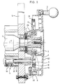
- FIG. 1 of a device for braking a measuring spindle 1 in a balancing machine, in particular a motor vehicle wheel balancing machine has a hand crank 2 as the drive device.
- the hand crank 2 With the hand crank 2, the measuring spindle 1 and the rotor clamped thereon in the figure, not shown in more detail, in particular the motor vehicle wheel, brought up to the measuring speed. The hand crank is then released and the unbalance measurement process is then carried out in the outlet.
- the hand crank 2 is fastened to a crank disk 20, to which a first brake disk 3 is integrally formed.
- the crank disc 20 and the first brake disc 3 are rotatably connected to the measuring spindle 1.
- a second brake disk 4 is provided, which rotates with the crank disk 20 or the first brake disk 3 and the measuring spindle 1 during the run-up and also during the run-out of the measuring spindle 1, during which the unbalance measurement is carried out.
- the second brake disk 4 is pressed against the first brake disk 3 by plate springs 21, which are supported on a housing frame 5, via an annular intermediate piece 28.
- the required braking force is also supplied by the plate springs 21 for the braking process to be explained.
- a holding pin 8 is mounted on the machine frame 5 parallel to the axis A of the measuring spindle 1.
- This holding pin 8 is mounted parallel to the axis A of the measuring spindle 1 and thus perpendicular to the direction of rotation of the second brake disc 4 and perpendicular to the disc plane of this brake disc 4 on the machine frame 5.
- An actuating device 11 is provided for the holding pin 8.
- This has an electromagnet 19 which acts as a lifting magnet.
- the retaining pin 8 is held in the rest position on the machine frame 5 by a spring 22, ie out of engagement with the second brake disc 4.
- the electromagnet 19 By briefly feeding the electromagnet 19, the holding pin 8 is brought into the position shown in dashed lines in FIG. 1 against the force of the spring 22.
- This lifting movement takes place, as will be explained, in a controlled manner, so that the brake disc 4 is brought into a fixed position on the housing frame 5 in a manner that is gentle on the material.
- the second brake disc 4 has engagement points for the holding pin 8.
- two engagement points 6 and 7 are shown in the form of radially extending stop arms.
- the second brake disk preferably has four stop arms as engagement points for the holding pin 8.
- an incremental encoder device is provided, which emits pulses that provide a statement about the respective angle of rotation position of the engagement points on the second brake disk 4 after corresponding evaluation .
- a scanning device 9 is provided on the machine frame 5, which optically scans a toothing 25 provided on the crank disk 20 around the entire circumference.
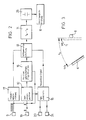
- the scanning device 9, as shown in FIG. 2 supplies a continuous pulse chain, each pulse indicating an angle of rotation step of the crank disk 20 and the rotating second brake disk 4.
- a second scanning device 10 is provided, which scans the permanent magnets 18, which have a marking function and are arranged on the scanning arms 6 and 7. As shown in FIG.
- the scanning device 10 delivers a pulse each time a permanent magnet 18 passes. It is not necessary for each stop arm to have a permanent magnet 18 as a marking. It is enough if one of the stop arms has the marking permanent magnet 18. If the other stop arms, which form the engagement points for the holding pin 8, have the same angular distances from one another, the respective position of the other holding pins, which do not have the marking 18, can be determined by a simple computer circuit and then taken into account when the holding pin 8 is actuated in a controlled manner .
- the crank disc 20 and thus the molded-on first brake disc 3 and the second brake disc 4 are made of plastic.
- the surface of these brake discs is designed so that at the contact surfaces between the two brake discs 3 and 4 in cooperation with the plate springs 21, which provide the required driving force, a sufficient braking torque for braking the spindle 1 with the rotor attached thereto, in particular a motor vehicle wheel to reach.
- FIG. 2 shows the evaluation and control circuit by means of which the holding pin 8 is actuated in a targeted manner to initiate the braking process after the imbalance measurement has ended in the outlet.
- the circuit arrangement has a speed measuring device 17 which is connected to the scanning device 9.
- the speed measuring device 17 evaluates the pulses supplied by the scanning device 9 in such a way that it delivers an output signal proportional to the speed of the spindle 1 and the two brake disks 3 and 4.
- a rotation angle position circuit 12 is connected to the scanning device 9 and to the scanning device 10.
- the Scanning device 10 a pulse that is caused by the mark 18 on the second brake disc 4. This pulse can serve as a reference pulse for a rotation angle position measurement in connection with the pulse chain supplied by the scanning device 9.
- this pulse indicates the respective position of the stop arm or arms, which form the engagement points 6 and 7 on the second brake disc 4.
- the angle of rotation position circuit provides an output signal which is proportional to the respective angle of rotation position of the spindle 1 and the two brake disks 3 and 4.
- This means that the output signal of the rotational angle position circuit 12 is also used in the determination of the unbalance angle position in measuring electronics 15, in which the measuring signals supplied by sensors 23 and 24 are evaluated.
- the transducers 23 and 24 are designed in a known manner and provide measurement signals which are proportional to the forces or vibrations emanating from the measuring spindle 1. These measurement signals are evaluated in the measurement electronics 15 in a known manner.
- the output signal of the rotational angle position circuit 12 is also fed to a rotational angle position transmitter circuit 16.
- the output signal of the scanning device 10 is also fed to this rotational angle position transmitter circuit 16.
- the rotational angle position transmitter circuit 16 evaluates these two supplied signals in such a way that it indicates the respective rotational angle position of the engagement points, ie the stop arms 6 and 7, on the second brake disk 4. An output signal corresponding to this respective angle of rotation position of the engagement points is supplied by the angle of rotation position transmitter circuit 16.
- a timing circuit 13 is connected to the output of the transmitter circuit 16.
- the timing circuit 13 also receives from the measuring electronics 15 a signal indicating the end of the unbalance measuring process. Furthermore, the time measurement circuit 13 receives the signal proportional to the speed from the speed measuring device 17. Since this signal is continuously supplied, the time measurement circuit 13 also receives data about the instantaneous speed of the spindle 1 and the two rotating brake disks 3 and 4 at the time at which the unbalance measurement has ended.
- the time measurement circuit 13 contains a dividing circuit which divides the Signal that indicates the instantaneous speed Do at the end of the unbalance measurement with the signal that indicates the instantaneous angular position ⁇ o of the stop arm closest to the retaining pin 8 on the second brake disk 4, as seen in the direction of rotation.
- this stop arm is designated 6.
- a time difference circuit 14 is provided which determines the time interval t 1 from Time interval to subtracted.
- the time interval t 1 is the time which is required to bring the holding pin 8 out of the rest position into the dashed engagement position shown in FIG. 1.
- t1 also includes a small default time, which ensures that the retaining pin 8 is safely in the engaged position before the stop arm 6 reaches this position (dashed position in Fig. 3).
- the time interval t1 can be easily determined and stored in a memory device in the time difference circuit 14.
- the time difference circuit 14 then carries out the difference formation to - t1 and thus determines the exact point in time at which the electromagnet 19 is briefly supplied, for example by discharging a capacitor in a driver stage 26, and thus the holding pin 8 is brought into the engagement position.
- the invention also provides braking that is independent of the direction of rotation, so that measuring runs can be carried out in both directions of rotation with the balancing measuring device actuated by means of a hand crank.
Landscapes
- Physics & Mathematics (AREA)
- General Physics & Mathematics (AREA)
- Testing Of Balance (AREA)
Description
Die Erfindung betrifft eine Vorrichtung an einer Auswuchtmaschine, zum Abbremsen der Meßspindel, die mit Hilfe einer Handkurbel auf Meßdrehzahl bringbar ist, mit zwei Bremsscheiben, von denen die erste Bremsscheibe drehfest mit der Meßspindel verbunden ist, und die zweite Bremsscheibe beim Bremsvorgang in einer gegenüber dem Maschinenrahmen stillstehenden Position fixiert ist.The invention relates to a device on a balancing machine for braking the measuring spindle, which can be brought to the measuring speed with the aid of a hand crank, with two brake disks, of which the first brake disk is connected in a rotationally fixed manner to the measuring spindle, and the second brake disk during the braking process in one compared to the Machine frame stationary position is fixed.
Es bereitet Schwierigkeiten, mit Hilfe von Eingriffsmitteln die zweite Bremsscheibe materialschonend in der stillstehenden Position am Maschinenrahmen zu fixieren.It is difficult to fix the second brake disc to the machine frame in the stationary position, in a manner that is gentle on the material, with the aid of engagement means.
Aufgabe der Erfindung ist es daher, eine materialschonende Fixierung der zweiten Bremsscheibe am Maschinenrahmen zur Einleitung des Abbremsvorgangs bei der eingangs genannten Vorrichtung zu erreichen.The object of the invention is therefore to achieve a material-saving fixation of the second brake disc on the machine frame to initiate the braking process in the device mentioned at the beginning.
Diese Aufgabe wird erfindungsgemäß dadurch gelöst, daß zum Fixieren der zweiten während des Unwuchtmeßvorgangs im ungebremsten Zustand mit der Meßspindel umlaufenden Bremsscheibe in der stillstehenden Position am Maschinenrahmen an der zweiten Bremsscheibe eine oder mehrere Eingriffstellen für einen am Maschinenrahmen senkrecht zur Drehrichtung der zweiten Bremsscheibe verschiebbar gelagerten Haltestift vorgesehen sind und daß nach Beendigung des Unwuchtmeßvorgangs der Haltestift in Abhängigkeit von der Drehwinkelposition und der Drehzahl der zweiten Bremsscheibe gesteuert mit einer Eingriffstelle an der zweiten Bremsscheibe durch eine Betätigungseinrichtung als Gegenlager für die Erzeugung eines Bremsmoments in Eingriff bringbar ist.This object is achieved in that in order to fix the second brake disc rotating during the unbalance measurement in the unbraked state with the measuring spindle in the stationary position on the machine frame on the second brake disc one or more engagement points for one on the machine frame perpendicular to the direction of rotation of the second brake disc slidably mounted retaining pin are provided and that after the imbalance measurement process, the retaining pin can be brought into engagement with an engagement point on the second brake disc by an actuating device as a counter bearing for the generation of a braking torque depending on the rotational angle position and the rotational speed of the second brake disc.
Für die Unwuchtmessung wird die Auswuchtmaschine mit Hilfe der Handkurbel auf Meßdrehzahl gebracht. Im Auslauf wird dann die Unwuchtmessung durchgeführt. Dabei laufen die beiden Bremsscheiben mit der Meßspindel um.For the unbalance measurement, the balancing machine is brought to the measuring speed using the hand crank. The unbalance measurement is then carried out in the outlet. The two brake disks rotate with the measuring spindle.
Zum Abbremsen wird der Haltestift mit einer der Eingriffstellen an der zweiten Bremsscheibe gesteuert in Eingriff gebracht. Diese Steuerung erfolgt gezielt in Abhängigkeit von der Position der dem Haltestift zunächst liegenden Eingriffstelle an der Bremsscheibe und der Drehzahl, die die mit der Meßspindel umlaufende zweite Bremsscheibe hat. Hierdurch wird erreicht, daß der Haltestift exakt mit der Eingriffstelle an der Bremsscheibe in Eingriff kommt.For braking, the holding pin is brought into controlled engagement with one of the engagement points on the second brake disk. This control takes place in a targeted manner as a function of the position of the engagement point on the brake disk initially lying on the holding pin and the rotational speed which the second brake disk rotating with the measuring spindle has. This ensures that the retaining pin engages exactly with the point of engagement on the brake disc.
In bevorzugter Weise sind die Eingriffstellen an der anzuhaltenden Bremsscheibe als radial abstehende Anschlagarme ausgebildet. Bei diesem Ausführungsbeispiel wird erreicht, daß der Anschlagstift exakt kurz vor der Anschlagkante am Haltearm in die Eingriffsposition gebracht wird, wofür eine kurzzeitig einwirkende Betätigungskraft auf den Haltestift ausreicht. Nachdem der Haltestift mit der Anschlagkante am Anschlagarm in Eingriff ist, wird durch das Drehmoment, das beim Abbremsen zur Wirkung kommt und das vom Haltestift als Gegenlager aufgenommen wird, der Haltestift selbsttätig in der Eingriffsposition gehalten. Für die Betätigung des Haltestiftes genügt daher eine nur kurzzeitige Energiezufuhr zur Betätigungseinrichtung, die bevorzugt einen als Hubmagnet wirkenden Elektromagneten zur Betätigung des Haltestiftes aufweist. Da nur ein geringer Energieaufwand erforderlich ist, kann der Elektromagnet auch batteriegespeist sein. Es ist daher nicht erforderlich, diesen ans Netz anzuschließen.The engagement points on the brake disc to be stopped are preferably designed as radially projecting stop arms. In this embodiment it is achieved that the stop pin is brought into the engagement position exactly shortly before the stop edge on the holding arm, for which a briefly acting actuating force on the holding pin is sufficient. After the retaining pin engages with the stop edge on the stop arm, the torque that comes into effect when braking and that of the retaining pin acts as Counter bearing is received, the holding pin automatically held in the engaged position. For the actuation of the holding pin, therefore, a brief supply of energy to the actuating device is sufficient, which preferably has an electromagnet acting as a lifting magnet for actuating the holding pin. Since only a small amount of energy is required, the electromagnet can also be battery-powered. It is therefore not necessary to connect it to the network.
Die beiden Bremsscheiben können in bevorzugter Weise aus Kunststoff, insbesondere auf dem Markt erhältlichte Thermoplaste, bestehen, so daß sie eine gewisse Elastizität aufweisen und aufgrund ihrer Materialeigenschaft die erforderliche Bremswirkung herbeiführen. Aufgrund dieser Materialwahl wird ferner noch der Vorteil erzielt, daß keine Schlagwirkung auftritt, was bei harten Materialien der Fall ist.The two brake discs can preferably be made of plastic, in particular thermoplastics available on the market, so that they have a certain elasticity and, due to their material properties, bring about the required braking effect. Because of this choice of material, there is also the advantage that there is no impact effect, which is the case with hard materials.
Um eine ständige Aussage über die momentane Drehwinkelposition der Eingriffstellen bzw. der Anschlagarme an der zweiten Bremsscheibe zu haben, können in bekannter Weise Drehwinkelgeber und ein Bezugsmarkengeber vorgesehen sein. Diese können als Ingrementalgeber (Impulsgeber) ausgebildet sein. Um einen Bezugsimpuls für die Drehwinkelbestimmung zu haben, kann an der zweiten Bremsscheibe, die am Maschinenrahmen beim Bremsvorgang zu fixieren ist, eine Markierung, beispielsweise in Form eines Permanentmagneten, vorhanden sein. Dieser Pergamentmagnet kann abgetastet werden, und der gewonnene Impuls bzw. das gewonnene Signal ist das Bezugssignal für die Drehwinkelpositionierung. Aus diesem Bezugssignal kann dann auch die Position der übrigen Eingriffstellen rechnerisch ermittelt werden. Es ist natürlich auch möglich, daß jede Eingriffstelle mit einer Markierung bzw. mit einem Magneten versehen ist.In order to have a constant statement about the current angle of rotation position of the engagement points or the stop arms on the second brake disk, angle of rotation sensors and a reference mark sensor can be provided in a known manner. These can be designed as incremental encoders. In order to have a reference pulse for determining the angle of rotation, a marking, for example in the form of a permanent magnet, can be present on the second brake disc, which is to be fixed on the machine frame during the braking process. This parchment magnet can be scanned and the pulse or signal obtained is the reference signal for the rotation angle positioning. From this reference signal, the position of the other intervention points can then also be determined mathematically. It is natural it is also possible for each point of engagement to be provided with a marking or with a magnet.
Die Abbremsvorrichtung kommt bevorzugt bei Auswuchtmaschinen zum Einsatz, mit denen Unwuchten anKraftfahrzeugreifen gemessen werden.The braking device is preferably used in balancing machines with which unbalances on motor vehicle tires are measured.
Anhand der Figuren wird an einem Ausführungsbeispiel die Erfindung noch näher erläutert. Es zeigt:
- Fig. 1
- eine Abbremsvorrichtung, die ein Ausführungsbeispiel der Erfindung ist;
- Fig. 2
- ein Blockschaltbild einer Steuerschaltung für die Betätigungseinrichtung, welche bei dem in der Fig. 1 dargestellten Ausführungsbeispiel vorgesehen ist;
- Fig. 3
- eine schematische Darstellung zur Erläuterung des Steuerungsbetriebs der in Fig. 2 dargestelllten Steuerschaltung.
- Fig. 1
- a braking device which is an embodiment of the invention;
- Fig. 2
- a block diagram of a control circuit for the actuator, which is provided in the embodiment shown in FIG. 1;
- Fig. 3
- is a schematic representation for explaining the control operation of the control circuit shown in Fig. 2.
Das in der Fig. 1 dargestellte Ausführungsbeispiel einer Vorrichtung zum Abbremsen einer Meßspindel 1 in einer Auswuchtmaschine, insbesondere Kraftfahrzeugradauswuchtmaschine, besitzt als Antriebseinrichtung eine Handkurbel 2. Mit der Handkurbel 2 wird die Meßspindel 1 und der darauf aufgespannte in der Fig. nicht näher dargestellte Rotor, insbesondere das Kraftfahrzeugrad, auf Meßdrehzahl gebracht. Die Handkurbel wird dann losgelassen, und im Auslauf wird dann der Unwuchtmeßvorgang durchgeführt.The embodiment shown in FIG. 1 of a device for braking a measuring spindle 1 in a balancing machine, in particular a motor vehicle wheel balancing machine, has a
Die Handkurbel 2 ist an einer Kurbelscheibe 20 befestigt, an die einstückig eine erste Bremsscheibe 3 angeformt ist. Die Kurbelscheibe 20 und die erste Bremsscheibe 3 sind drehfest mit der Meßspindel 1 verbunden.The
Ferner ist eine zweite Bremsscheibe 4 vorgesehen, die während des Hochlaufs und auch während des Auslaufs der Meßspindel 1, während welchem die Unwuchtmessung durchgeführt wird, mit der Kurbelscheibe 20 bzw. der ersten Bremsscheibe 3 und der Meßspindel 1 mitumläuft. Die zweite Bremsscheibe 4 wird durch Tellerfedern 21, welche an einem Gehäuserahmen 5 abgestützt sind, über ein ringförmiges Zwischenstück 28, an die erste Bremsscheibe 3 angedrückt. Durch die Tellerfedern 21 wird für den noch zu erläuternden Bremsvorgang auch die erforderliche Bremskraft geliefert.Furthermore, a second brake disk 4 is provided, which rotates with the
Am Maschinenrahmen 5 ist parallel zur Achse A der Meßspindel 1 ein Haltestift 8 gelagert. Dieser Haltestift 8 ist parallel zur Achse A der Meßspindel 1 und damit senkrecht zur Drehrichtung der zweiten Bremsscheibe 4 und senkrecht zur Scheibenebene dieser Bremsscheibe 4 verschiebbar am Maschinenrahmen 5 gelagert. Für den Haltestift 8 ist eine Betätigungseinrichtung 11 vorgesehen. Diese weist einen als Hubmagneten wirkenden Elektromagneten 19 auf. Durch eine Feder 22 ist der Haltestift 8 in der Ruheposition am Maschinenrahmen 5, d.h. außer Eingriff mit der zweiten Bremsscheibe 4, gehalten. Durch kurzzeitiges Speisen des Elektromagneten 19 wird der Haltestift 8 in die in der Fig. 1 strichlierte Position entgegen der Kraft der Feder 22 gebracht. Diese Hubbewegung erfolgt, wie noch erläutert wird, in gesteuerter Art und Weise, so daß die Bremsscheibe 4 materialschonend in eine am Gehäuserahmen 5 fixierte Position gebracht wird.A
Die zweite Bremsscheibe 4 besitzt Eingriffstellen für den Haltestift 8. Beim dargestellten Ausführungsbeispiel sind zwei Eingriffstellen 6 und 7 in Form von radial sich erstreckenden Anschlagarmen gezeigt. In bevorzugter Weise besitzt die zweite Bremsscheibe vier Anschlagarme als Eingriffstellen für den Haltestift 8.The second brake disc 4 has engagement points for the
Um eine Aussage über die jeweilige Drehwinkelposition der als Eingriffstellen 6 und 7 wirkenden Anschlagarme an der zweiten Bremsscheibe 4 zu haben, ist eine Inkrementalgebereinrichtung vorgesehen, welche Impulse abgibt, die eine Aussage über die jeweilige Drehwinkelpositionierung der Eingriffstellen an der zweiten Bremsscheibe 4 nach entsprechender Auswertung liefern. Hierzu sind am Maschinenrahmen 5 eine Abtasteinrichtung 9 vorgesehen, welche eine an der Kurbelscheibe 20 um den ganzen Umfang vorgesehene Zahnung 25 optisch abtastet.
Die Abtasteinrichtung 9 liefert, wie in der Fig. 2 gezeigt ist, eine fortlaufende Impulskette, wobei jeder Impuls einen Drehwinkelschritt der Kurbelscheibe 20 und der sich mitdrehenden zweiten Bremsscheibe 4 angibt. Ferner ist eine zweite Abtasteinrichtung 10 vorgesehen, welche die an den Abtastarmen 6 und 7 angeordneten Permanentmagnete 18, welche Markierungsfunktion haben, abtastet. Die Abtasteinrichtung 10 liefert, wie in der Fig. 2 dargestellt ist, jeweils dann, wenn ein Permanentmagnet 18 vorbeiläuft, einen Impuls. Es ist nicht erforderlich, daß jeder Anschlagarm einen Permanentmagneten 18 als Markierung aufweist. Es genügt, wenn einer der Anschlagarme den markierenden Permanentmagneten 18 aufweist. Wenn die übrigen Anschlagarme, welche die Eingriffstellen für den Haltestift 8 bilden, gleiche Winkelabstände voneinander haben, läßt sich durch eine einfache Rechnerschaltung die jeweilige Position der anderen Haltestifte, welche nicht die Markierung 18 haben, ermitteln und dann bei der gesteuerten Betätigung des Haltestiftes 8 berücksichtigen.In order to have a statement about the respective angle of rotation position of the stop arms acting as
The
Die Kurbelscheibe 20 und damit die angeformte erste Bremsscheibe 3 sowie die zweite Bremsscheibe 4 bestehen aus Kunststoff. Die Oberfläche dieser Bremsscheiben ist so ausgebildet, daß an den Berührungsflächen zwischen den beiden Bremsscheiben 3 und 4 in Zusammenwirkung mit den Tellerfedern 21, die die erforderliche Antriebskraft liefern, ein ausreichendes Bremsmoment zum Abbremsen der Spindel 1 mit dem daran befestigten Rotor, insbesondere Kraftfahrzeugrad, zu erreichen.The
In der Fig. 2 ist die Auswerte- und Steuerschaltung dargestellt, durch welche eine gezielte Betätigung des Haltestiftes 8 zum Einleiten des Bremsvorgangs nach Beendigung der Unwuchtmessung im Auslauf erreicht wird. Die Schaltungsanordnung weist eine Drehzahlmeßeinrichtung 17 auf, die an die Abtasteinrichtung 9 angeschlossen ist. Die Drehzahlmeßeinrichtung 17 wertet die von der Abtasteinrichtung 9 gelieferten Impulse dahingehend aus, daß sie ein der Drehzahl der Spindel 1 und der beiden Bremsscheiben 3 und 4 proportionales Ausgangssignal liefert. An die Abtasteinrichtung 9 und an die Abtasteinrichtung 10 ist eine Drehwinkelpositionsschaltung 12 angeschlossen. Wie schon erläutert, liefert die Abtasteinrichtung 10 einen Impuls, der durch die Markierung 18 an der zweiten Bremsscheibe 4 hervorgerufen wird. Dieser Impuls kann als Bezugsimpuls für eine Drehwinkelpositionsmessung in Zusammenhang mit der von der Abtasteinrichtung 9 gelieferten Impulskette dienen. Ferner gibt dieser Impuls die jeweilige Lage des bzw. der Anschlagarme, welche die Eingriffstellen 6 und 7 an der zweiten Bremsscheibe 4 bilden, an. Die Drehwinkelpositionsschaltung liefert ein Ausgangssignal, das proportional der jeweiligen Drehwinkelstellung der Spindel 1 und der beidenBremsscheiben 3 und 4 ist. Das bedeutet, daß das Ausgangssignal der Drehwinkelpositionsschaltung 12 auch bei der Ermittlung der Unwuchtwinkellage in einer Meßelektronik 15, in welcher die von Meßwertgebern 23 und 24 gelieferten Meßsignale ausgewertet werden, verwendet wird. Die Meßwertgeber 23 und 24 sind in bekannter Weise ausgebildet und liefern Meßsignale, die den von der Meßspindel 1 ausgehenden Kräften bzw. Schwingungen proportional sind. Die Auswertung dieser Meßsignale erfolgt in der Meßelektronik 15 in bekannter Weise.FIG. 2 shows the evaluation and control circuit by means of which the holding
Das Ausgangssignal der Drehwinkelpositionsschaltung 12 wird ferner einer Drehwinkelpositionsgeberschaltung 16 zugeführt. Dieser Drehwinkelpositionsgeberschaltung 16 wird ferner das Ausgangssignal der Abtasteinrichtung 10 zugeführt. Die Drehwinkelpositionsgeberschaltung 16 wertet diese beiden zugeleiteten Signale in der Weise aus, daß sie die jeweilige Drehwinkelposition der Eingriffstellen, d.h. der Anschlagarme 6 und 7, an der zweiten Bremsscheibe 4 angibt. Ein dieser jeweiligen Drehwinkelposition der Eingriffstellen entsprechendes Ausgangssignal wird von der Drehwinkelpositionsgeberschaltung 16 geliefert.The output signal of the rotational
An den Ausgang der Geberschaltung 16 ist eine Zeitbemessungsschaltung 13 angeschlossen. Die Zeitbemessungsschaltung 13 empfängt ferner von der Meßelektronik 15 ein Signal, das das Ende des Unwuchtmeßvorgangs angibt. Ferner empfängt die Zeitbemessungsschaltung 13 von der Drehzahlmeßeinrichtung 17 das der Drehzahl proportionale Signal. Da dieses Signal ständig geliefert wird, erhält die Zeitbemessungsschaltung 13 auch zu dem Zeitpunkt, an welchem die Unwuchtmessung beendet ist, Daten über die Momentandrehzahl der Spindel 1 und der beiden mitlaufenden Bremsscheiben 3 und 4. Die Zeitbemessungsschaltung 13 enthält eine Dividierschaltung, welche eine Division des Signals, das die Momentandrehzahl Do beim Ende der Unwuchtmessung angibt, mit dem Signal, das die momentane Winkelposition ωo des in Drehrichtung gesehen dem Haltestift 8 nächstliegenden Anschlagarmes an der zweiten Bremsscheibe 4 angibt, durchführt. In der Fig. 3 ist dieser Anschlagarm mit 6 bezeichnet. Die Dividierschaltung in der Zeitbemessungsschaltung 13 führt mithin folgenden Rechenvorgang aus:![]()
to bedeutet die Zeit, welche der Anschlagarm 6 benötigt, um mit der ermittelten Momentandrehzahl ![]()
![]()
![]()
to means the time that the ![]()
![]()
Durch diese gezielte Steuerung der Betätigungseinrichtung 11, die den Haltestift 8 in die Eingriffsposition bringt, genügt es, auf den Haltestift 8 relativ kurzzeitig die Hubkraft zur Einwirkung zu bringen. Wenn der Anschlagarm 6 am Haltestift 8 anliegt, wird dieser durch das zur Wirkung kommende Bremsmoment, für welches dann der Haltestift 8 ein Gegenlager bildet, selbsttätig in der Eingriffsposition gehalten.Through this targeted control of the
Da die Zeit, welche der Haltestift 8 benötigt, um von der Ruheposition in die Eingriffsposition zu kommen, bekannt ist, läßt sich das Zeitinterval t1 einfach bestimmen und in einer Speichereinrichtung in der Zeitdifferenzschaltung 14 ablegen. Die Zeitdifferenzschaltung 14 führt dann die Differenzbildung to - t1 durch und bestimmt damit den exakten Zeitpunkt, zu welchem beispielsweise durch Entladen eines Kondensators in einer Treiberstufe 26 der Elektromagnet 19 kurzzeitig gespeist wird und damit der Haltestift 8 in die Eingriffsposition gebracht wird.Since the time required for the holding
In vorteilhafter Weise gewinnt man bei der Erfindung ferner eine drehrichtungsunabhängige Bremsung, so daß mit der durch Handkurbel betätigten Auswuchtmeßeinrichtung in beiden Drehrichtungen Meßläufe durchgeführt werden können.Advantageously, the invention also provides braking that is independent of the direction of rotation, so that measuring runs can be carried out in both directions of rotation with the balancing measuring device actuated by means of a hand crank.
Claims (11)
- Apparatus on a balancing machine for retarding the measuring spindle (1) which can be brought up to a measuring speed of rotation by means of a hand crank (2), comprising two brake discs (3, 4) of which the first brake disc (3) is non-rotatably connected to the measuring spindle and the second brake disc (4) is fixed in the braking operation in a position which is stationary relative to the machine frame (5), characterised in that for the purposes of fixing the second brake disc (4) in the stationary position on the machine frame (5), which brake disc (4) rotates with the measuring spindle (1) during the unbalance measuring operation in an unbraked condition, provided on the second brake disc are one or more engagement locations (6, 7) for a holding pin (8) which is mounted on the machine frame (5) displaceably perpendicularly to the direction of rotation of the second brake disc (4), and that after termination of the unbalance measuring operation the holding pin (8), in dependence on the rotational angular position and the speed of rotation of the second brake disc (4), can be brought into engagement in a controlled fashion with an engagement location (6, 7) on the second brake disc (4) by an actuating means (11) as a support means, for producing a braking moment.
- Apparatus according to claim 1 characterised in that provided on the second brake disc (4) is at least one marking (18) which can be sensed and which is associated with the engagement locations (6, 7), and that there is provided a monitoring means (9, 10, 12, 13, 16) which monitors the respective rotational angular position of the second brake disc and which is connected to the actuating means (11) in such a way that after termination of the unbalance measuring operation the actuating means (11) brings the holding pin (8) specifically into engagement with one of the engagement locations (6, 7).
- Apparatus according to claim 1 or claim 2 characterised in that the actuating means (11) exerts on the holding pin (8) a force which acts briefly thereon and that the holding pin (8) is automatically held in engagement with the engagement location (6, 7) on the second brake disc (4).
- Apparatus according to one of claims 1 to 3 characterised in that a plurality of engagement locations (6, 7) are provided at equal angular spacings from each other on the second brake disc (4).
- Apparatus according to one of claims 1 to 4 characterised in that the engagement locations (6, 7) are in the form of abutment arms which project radially from the second brake disc (4).
- Apparatus according to one of claims 1 to 5 characterised in that the two brake discs (3, 4) comprise plastics material.
- Apparatus according to one of claims 1 to 6 characterised in that the actuating means (11) for actuation of the holding pin (8) is actuated, after the output of a signal indicating the end of the unbalance measuring operation, by a rotary speed measuring means (17) which supplies a signal that is proportional to the speed of rotation of the second brake disc (4), and a rotational angular position sensing means (16) which supplies a signal that is proportional to the respective rotational angular position of the engagement locations (6, 7) on the second brake disc (4).
- Apparatus according to one of claims 1 to 7 characterised in that the actuating means (11) has a solenoid (19).
- Apparatus according to claim 8 characterised in that the solenoid (19) is battery-powered.
- Apparatus according to one of claims 1 to 9 characterised in that provided for forming the signal which is proportional to the speed of rotation are sensing means (9, 10) which are in the form of an incremental generator and a reference signal generator and which sense the rotary movement of the spindle (1) and the second brake disc (4).
- Apparatus according to claim 10 characterised in that the output signals of the sensing means (9, 10) are also fed to an electronic measuring means (15) connected to measurement value generators (23, 24), for calculation of the angular position of the unbalance.
Applications Claiming Priority (2)
| Application Number | Priority Date | Filing Date | Title |
|---|---|---|---|
| DE4028335 | 1990-09-06 | ||
| DE4028335A DE4028335A1 (en) | 1990-09-06 | 1990-09-06 | DEVICE FOR BRAKING A MEASURING SPINDLE OF A BALANCING MACHINE |
Publications (3)
| Publication Number | Publication Date |
|---|---|
| EP0473939A2 EP0473939A2 (en) | 1992-03-11 |
| EP0473939A3 EP0473939A3 (en) | 1993-01-13 |
| EP0473939B1 true EP0473939B1 (en) | 1995-05-17 |
Family
ID=6413755
Family Applications (1)
| Application Number | Title | Priority Date | Filing Date |
|---|---|---|---|
| EP91112800A Expired - Lifetime EP0473939B1 (en) | 1990-09-06 | 1991-07-30 | Braking device with a hand driven balancing machine |
Country Status (5)
| Country | Link |
|---|---|
| US (1) | US5255563A (en) |
| EP (1) | EP0473939B1 (en) |
| JP (1) | JPH055667A (en) |
| DE (1) | DE4028335A1 (en) |
| ES (1) | ES2074195T3 (en) |
Families Citing this family (3)
| Publication number | Priority date | Publication date | Assignee | Title |
|---|---|---|---|---|
| DE19636267C2 (en) * | 1996-09-06 | 1998-08-13 | Hofmann Werkstatt Technik | Method for stopping a rotor mounted on a main shaft of a balancing machine and driven by an electric motor |
| CN102980723A (en) * | 2012-11-20 | 2013-03-20 | 凡嘉科技(无锡)有限公司 | Dynamic balance adjusting device of rotating products |
| CN117516804B (en) * | 2023-12-29 | 2024-05-10 | 三峡金沙江云川水电开发有限公司 | Dynamic balance detection device for rotating shaft of high-voltage motor |
Family Cites Families (10)
| Publication number | Priority date | Publication date | Assignee | Title |
|---|---|---|---|---|
| DE1082066B (en) * | 1958-06-03 | 1960-05-19 | Siemens Ag | Method and device for balancing high-speed machine runners |
| DE2243002B1 (en) * | 1972-09-01 | 1973-11-15 | Gebr. Hofmann Kg Maschinenfabrik, 6100 Darmstadt | Method and device for balancing rotors |
| US3866489A (en) * | 1973-11-16 | 1975-02-18 | Cincinnati Milacron Inc | Dynamic balancing apparatus |
| CH610404A5 (en) * | 1975-10-27 | 1979-04-12 | Luigi Buzzi | |
| US4435982A (en) * | 1981-02-20 | 1984-03-13 | Balco, Inc. | Machine and method for balancing wheels |
| US4467649A (en) * | 1982-05-25 | 1984-08-28 | American Hofmann Corporation | Apparatus for balancing rotatable bodies |
| US4480472A (en) * | 1982-08-10 | 1984-11-06 | Hofmann Corporation Automotive Service Equipment | Electronic wheel balancer for vehicle wheels |
| US4489607A (en) * | 1983-05-23 | 1984-12-25 | Park Hyo Sup | Dynamic vehicle tire and wheel balancing system |
| CA1230758A (en) * | 1984-01-19 | 1987-12-29 | Willy Borner | Machine and method for balancing relatively large objects such as truck tires |
| DE3730084A1 (en) * | 1987-09-08 | 1989-03-16 | Hofmann Werkstatt Technik | METHOD FOR STOPPING THE MEASURING RUN OF A ROTOR TO BE BALANCED |
-
1990
- 1990-09-06 DE DE4028335A patent/DE4028335A1/en active Granted
-
1991
- 1991-07-30 EP EP91112800A patent/EP0473939B1/en not_active Expired - Lifetime
- 1991-07-30 ES ES91112800T patent/ES2074195T3/en not_active Expired - Lifetime
- 1991-08-27 US US07/750,316 patent/US5255563A/en not_active Expired - Fee Related
- 1991-08-31 JP JP3300007A patent/JPH055667A/en active Pending
Also Published As
| Publication number | Publication date |
|---|---|
| EP0473939A2 (en) | 1992-03-11 |
| DE4028335A1 (en) | 1992-03-12 |
| US5255563A (en) | 1993-10-26 |
| ES2074195T3 (en) | 1995-09-01 |
| DE4028335C2 (en) | 1993-01-28 |
| EP0473939A3 (en) | 1993-01-13 |
| JPH055667A (en) | 1993-01-14 |
Similar Documents
| Publication | Publication Date | Title |
|---|---|---|
| DE69936229T2 (en) | DEVICE FOR AUTOMATIC COMPENSATION OF LATERAL CIRCULAR ELEMENTS | |
| DE69731757T2 (en) | DEVICE AND METHOD FOR THE AUTOMATIC COMPENSATION OF LATERAL CIRCULAR ELEMENTS | |
| DE3935450C1 (en) | ||
| DE2107790C3 (en) | Device for determining the balance values of a vehicle wheel | |
| DE3605088A1 (en) | OPERATING DEVICE | |
| EP0382115A2 (en) | Control device for a belt drive | |
| DE2357505A1 (en) | DYNAMIC BALANCING MACHINE | |
| EP0756165B1 (en) | Method and device for calibrating of torque in measuring installation | |
| EP0327026B1 (en) | Method and device for balancing a vehicle wheel or the like | |
| EP0650042B1 (en) | Procedure and device for holding in position a vehicle wheel clamped on a measuring shaft of a balancing machine | |
| EP0473939B1 (en) | Braking device with a hand driven balancing machine | |
| DE10333396B4 (en) | Torque measuring device for electric motors and method for measuring the torque of an electric motor | |
| EP1333265B1 (en) | Measuring the unbalance of a motorcycle wheel with a loosening of the driver device by a sudden change of speed | |
| DE102018120058A1 (en) | A magnetic sensor having a sensor gear, an electric motor having the magnetic sensor, and a method of manufacturing a machine having the magnetic sensor | |
| EP4033255A1 (en) | Method for controlling the determination of a speed of a bicycle | |
| EP0457086B1 (en) | Contactless measurement of the local torque drag-in at wormmachines | |
| DE19716267C2 (en) | Method for balancing motor vehicle wheels | |
| DE1179787B (en) | Device on hobbing machines to reduce the pitch errors when hobbing gears and. like | |
| DE4015051A1 (en) | DEVICE AND METHOD FOR BALANCING A ROTOR | |
| CH463126A (en) | Drive device for the rotating movement of a machine table for carrying out the pitch test | |
| EP0555647B1 (en) | Procedure and device for determining the number of successive balancing operations | |
| DE4403218C2 (en) | Encoder | |
| DE2439768A1 (en) | GEAR TESTING MACHINE WITH FRICTION WHEEL DRIVEN MOUNTING TABLE AND POSITION ENCODER | |
| DE4437017C2 (en) | Device for the contactless measurement of the relative position and the rotational frequency of two bodies | |
| DE3541459C2 (en) |
Legal Events
| Date | Code | Title | Description |
|---|---|---|---|
| PUAI | Public reference made under article 153(3) epc to a published international application that has entered the european phase |
Free format text: ORIGINAL CODE: 0009012 |
|
| AK | Designated contracting states |
Kind code of ref document: A2 Designated state(s): AT BE CH DE DK ES FR GB GR IT LI LU NL SE |
|
| PUAL | Search report despatched |
Free format text: ORIGINAL CODE: 0009013 |
|
| AK | Designated contracting states |
Kind code of ref document: A3 Designated state(s): AT BE CH DE DK ES FR GB GR IT LI LU NL SE |
|
| 17P | Request for examination filed |
Effective date: 19930212 |
|
| RBV | Designated contracting states (corrected) |
Designated state(s): ES FR GB IT |
|
| REG | Reference to a national code |
Ref country code: DE Ref legal event code: 8566 |
|
| 17Q | First examination report despatched |
Effective date: 19941013 |
|
| GRAA | (expected) grant |
Free format text: ORIGINAL CODE: 0009210 |
|
| AK | Designated contracting states |
Kind code of ref document: B1 Designated state(s): ES FR GB IT |
|
| ET | Fr: translation filed | ||
| ITF | It: translation for a ep patent filed |
Owner name: DR. ING. A. RACHELI & C. |
|
| GBT | Gb: translation of ep patent filed (gb section 77(6)(a)/1977) |
Effective date: 19950703 |
|
| REG | Reference to a national code |
Ref country code: ES Ref legal event code: FG2A Ref document number: 2074195 Country of ref document: ES Kind code of ref document: T3 |
|
| PLBE | No opposition filed within time limit |
Free format text: ORIGINAL CODE: 0009261 |
|
| STAA | Information on the status of an ep patent application or granted ep patent |
Free format text: STATUS: NO OPPOSITION FILED WITHIN TIME LIMIT |
|
| 26N | No opposition filed | ||
| PGFP | Annual fee paid to national office [announced via postgrant information from national office to epo] |
Ref country code: FR Payment date: 19970711 Year of fee payment: 7 |
|
| PGFP | Annual fee paid to national office [announced via postgrant information from national office to epo] |
Ref country code: ES Payment date: 19970724 Year of fee payment: 7 |
|
| PGFP | Annual fee paid to national office [announced via postgrant information from national office to epo] |
Ref country code: GB Payment date: 19970729 Year of fee payment: 7 |
|
| PG25 | Lapsed in a contracting state [announced via postgrant information from national office to epo] |
Ref country code: GB Free format text: LAPSE BECAUSE OF NON-PAYMENT OF DUE FEES Effective date: 19980730 |
|
| PG25 | Lapsed in a contracting state [announced via postgrant information from national office to epo] |
Ref country code: ES Free format text: LAPSE BECAUSE OF NON-PAYMENT OF DUE FEES Effective date: 19980731 |
|
| GBPC | Gb: european patent ceased through non-payment of renewal fee |
Effective date: 19980730 |
|
| PG25 | Lapsed in a contracting state [announced via postgrant information from national office to epo] |
Ref country code: FR Free format text: LAPSE BECAUSE OF NON-PAYMENT OF DUE FEES Effective date: 19990331 |
|
| REG | Reference to a national code |
Ref country code: FR Ref legal event code: ST |
|
| REG | Reference to a national code |
Ref country code: ES Ref legal event code: FD2A Effective date: 19990811 |
|
| PG25 | Lapsed in a contracting state [announced via postgrant information from national office to epo] |
Ref country code: IT Free format text: LAPSE BECAUSE OF NON-PAYMENT OF DUE FEES Effective date: 20050730 |