EP0473682B1 - Nivelliervorrichtung - Google Patents
Nivelliervorrichtung Download PDFInfo
- Publication number
- EP0473682B1 EP0473682B1 EP90908720A EP90908720A EP0473682B1 EP 0473682 B1 EP0473682 B1 EP 0473682B1 EP 90908720 A EP90908720 A EP 90908720A EP 90908720 A EP90908720 A EP 90908720A EP 0473682 B1 EP0473682 B1 EP 0473682B1
- Authority
- EP
- European Patent Office
- Prior art keywords
- bar
- reference means
- levelling
- chain
- slide
- Prior art date
- Legal status (The legal status is an assumption and is not a legal conclusion. Google has not performed a legal analysis and makes no representation as to the accuracy of the status listed.)
- Expired - Lifetime
Links
- 230000000903 blocking effect Effects 0.000 claims description 5
- 238000006073 displacement reaction Methods 0.000 claims description 5
- 238000004804 winding Methods 0.000 claims description 2
- 238000004904 shortening Methods 0.000 claims 1
- 229910000831 Steel Inorganic materials 0.000 description 5
- 239000010959 steel Substances 0.000 description 5
- 238000001514 detection method Methods 0.000 description 2
- 230000003321 amplification Effects 0.000 description 1
- 238000003780 insertion Methods 0.000 description 1
- 230000037431 insertion Effects 0.000 description 1
- 238000003199 nucleic acid amplification method Methods 0.000 description 1
Images


Classifications
-
- G—PHYSICS
- G01—MEASURING; TESTING
- G01C—MEASURING DISTANCES, LEVELS OR BEARINGS; SURVEYING; NAVIGATION; GYROSCOPIC INSTRUMENTS; PHOTOGRAMMETRY OR VIDEOGRAMMETRY
- G01C15/00—Surveying instruments or accessories not provided for in groups G01C1/00 - G01C13/00
- G01C15/02—Means for marking measuring points
- G01C15/06—Surveyors' staffs; Movable markers
Definitions
- the present invention concerns a levelling bar, in the form of a simple bar or several telescopically into each other displaceable bars, to determine the elevation difference between different points and which is provided with a displaceable slide which can be locked in different positions, on which is arranged a level indicator.
- US-A-4 718 171 discloses a stadia rod for use in a levelling system.
- the elevation is determined for a number of marked points, whereby one starts from an index point with known or assumed elevation.
- a number of moving points are often also required, this involves a large number of calculations to be carried out, in order to obtain the required elevations.
- the object of the invention is to provide a levelling bar, which considerably simplifies the calculation of the elevations, especially when the elevation variations are large.
- This problem has been solved by providing the slide with a counter, which in cooperation with the bar/bars or a reference means fixed to said bar/bars is arranged to indicate the relative distance from one of the outer ends of the bar/bars to said level indicator.
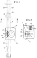
- Fig. 1 shows a lateral view of a first embodiment of the levelling bar according to the invention.
- Fig. 2 a section along the line II-II in fig. 1.
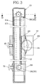
- Fig. 3 shows a longitudinal section through a second embodiment of the levelling bar according to the invention.
- Fig. 4 is a section along the line IV - IV in fig. 3.
- Fig. 5 shows a longitudinal section through a third embodiment of the levelling bar according to the invention.
- Fig. 6 shows a longitudinal section through a fourth embodiment of the levelling bar according to the invention.
- Fig. 7 is a section along the line VII-VII in fig. 6.
- the levelling bar contains of a profile bar with mainly U-shaped cross section.
- a reference means 12 which in the embodiment shown is constituted by a rack 13.
- a displacable slide 14 is provided, which by means of a clamping screw 15 is lockable in different displacement positions.
- a level indicator 16 is provided which contains a window 17 provided with an index mark (not shown) and on the outside of the mid section 19 of the profile bar a scale (not shown) is provided, the division of which can be brought into relation with the index mark.
- a counter 20 which contains a pinion 21 which is meshed into the rack 13 and which transmits its rotational movement by a suitable gear ratio to a number of digit wheels 22 which can be preset and also reset by a button 23.
- the counter When the slide is displaced along the profile bar 11 the counter thus will indicate the relative elevation of the slide 14, whereby the index point can either be a given elevation, which is fed into the counter as a presetting of the digit wheels 22 or one can start from a zero position.
- the levelling instrument is levelled towards the levelling bar, the slide of which is displaced such that the index of the level indicator coincides with the line of sight of the levelling instrument. In this position the slide is locked to the profile bar and the obtained digit value is read.
- the profile bar should be too short (a suitable length may be 2 meters), it can be lengthened by an extension bar in its upper end, which extension bar is provided with an insertion end, which trough a snap-on lock or the like can be joined to the profile bar.
- the extension bar 24 is provided with a rack 13, so that the rack without interruption also can be displaced along the extension bar 24.
- the levelling bar 10 consists of two telescopically into each other displaceable bar sections 11a and 11b.
- the outer bar section 11a in its upper end is provided with a first pulley 26 mounted in bearings in this end for an endless chain 27, which at the lower part of the outer bar section is conveyed around a second pulley 28.
- This is mounted in bearings in a bracket 29, which is inserted through a slot in the interior of the outer bar section 11a.
- the bracket is also provided with a clamping means 31, for clamping the two bar sections 11a and 11b to each other.
- the chain 27 constitutes the reference means 12, which cooperates with a pinion 21 mounted in bearings in the slide 14.
- a counter 20 is provided in the slide 14.
- a third and a fourth pulley 32 and 33 are arranged on the shafts of the pulleys 26 and 28 for a second endless chain 34.
- the level indicator 16 consists of a receiver 36, which emits an acoustic signal, when the level indicator and accordingly the slide 14 comes into position of sight with the levelling instrument.
- FIG. 5 A somewhat simplified version of the embodiment shown in fig. 3 and 4 is illustrated in fig. 5.
- a pulley 26 is provided at the upper end part of the outer bar section 11a for a chain 27, the ends which are secured to lower end part of the inner bar section 11b.
- an expansion device 18 is connected, which in the displayed embodiment consists of a tension spring 37, which is attached by an end plug 38 inserted in the outer end of the bar section 11b.
- a blocking means 39 is provided, which in active position blocks the pulley 26 and accordingly the chain 27, while in the withdrawn passive position the chain can run over the pulley 26, so that a relative displacement between the bar sections 11a and 11b can be carried out.
- the slide 14 is provided with a counter 20 with gear-wheel 21 which cooperates with the chain 27.
- the detection of the reference means 12 is carried out non- contact by means of a photo electric interrupter 40 connected to the slide 14.
- the reference means 12 consists of a windable steel strip 41, which is preferably provided with a longitudinal perforation through which the light beam can pass.
- the steel strip is connected to an expansion device 18 which in the embodiment shown consists a spring loaded wind up mechanism 42 which is arranged at the upper end part of the outer bar section, respectively one to the upper end part connectable end cover 43.
- the wind up mechanism 42 is provided with a blocking means which can be activated by a control button not shown, which blocking means blocks up the winding mechanism in activated position.
- the steel strip 41 with its free end firmly joined to the lower end part of the inner bar section 11b, so that when this is withdrawn and the blocking device 39 released the both bar sections can be displaced with respect to each other.
- the non-contact detection of the steel strip 41 is preferably carried out by means of a light-emitting diode as a transmitter and the output signal is fed if necessary after amplification to an electric counter, for example an electromagnetic impulse counter of known design.
- an electric counter for example an electromagnetic impulse counter of known design.
- a nonmagnetic strip can be used which is provided with magnetic scale divisions, which can be non-contact detected by means of a magnetic slot switch.
Landscapes
- Physics & Mathematics (AREA)
- Engineering & Computer Science (AREA)
- General Physics & Mathematics (AREA)
- Radar, Positioning & Navigation (AREA)
- Remote Sensing (AREA)
- A Measuring Device Byusing Mechanical Method (AREA)
- Soil Working Implements (AREA)
- Length-Measuring Instruments Using Mechanical Means (AREA)
- Transplanting Machines (AREA)
- Vehicle Body Suspensions (AREA)
- Mechanical Treatment Of Semiconductor (AREA)
- Continuous Casting (AREA)
- Displays For Variable Information Using Movable Means (AREA)
- Level Indicators Using A Float (AREA)
Claims (8)
- Nivellierinstrument in Gestalt einer einfachen Stange (11) oder mehrerer ineinander schiebbarer Stangenteile (11, 11b) zur Bestimmung des Niveauunterschieds zwischen unterschiedlichen Punkten, mit einem Schieber (14), der längs der Stange verstellbar sowie in unterschiedlichen Positionen festsetzbar und mit einer Niveauanzeige (16) versehen ist,
dadurch gekennzeichnet,
daß der Schieber (14) mit einer Zählvorrichtung (20) versehen ist, die mit der einfachen Stange/den Stangenteilen (11a, 11b) oder einer an der einfachen Stange/ den Stangenteilen befestigten Bezugseinrichtung (12) zusammenwirkend dazu vorgesehen ist, den relativen Abstand von einem der Außenenden der einfachen Stange oder der Stangenteile zu der Niveauanzeige (16) anzuzeigen. - Nivellierinstrument nach Anspruch 1,
dadurch gekennzeichnet,
daß die Zählvorrichtung (20) ein mit einer Ziffernanzeige (22), vorzugsweise mit Voreinstell- und Nullrückstelleinrichtungen versehenener Zähler ist, der so angeordnet ist, daß er durch einen Wandler (21, 40) aktiviert wird, der dazu vorgesehen ist, die Bezugseinrichtung (12) zu erfassen oder dafür mit dieser im Eingriff zu stehen. - Nivellierinstrument nach Anspruch 2,
dadurch gekennzeichnet,
daß die Stange (11) zumindest zwei teleskopische, ineinander schiebbare und in unterschiedlichen Positionen festsetzbare Stangenteile (11a, 11b) enthält, daß die aus einer Kette (27), einem flexiblen Streifen (12) oder dgl. bestehende Bezugseinrichtung (12) dazu vorgesehen ist, sich zwischen den Endbereichen der beiden Stangenteile (11a, 11b) zu erstrecken, daß die Bezugseinrichtung mit einer Expansionsvorrichtung (18) zusammenwirkt, die dazu ausgebildet ist, eine Verlängerung bzw. Verkürzung der Bezugseinrichtung (12) bei der relativen Verstellung der Stangenteile (11a, 11b) zuzulassen, und daß eine Festsetzeinrichtung zum Hemmen bzw. Freigeben der Verstellbewegung der Bezugseinrichtung (12) vorgesehen ist. - Nivellierinstrument nach Anspruch 3,
dadurch gekennzeichnet,
daß die Bezugseinrichtung aus einer Endloskette (27), einem Streifen oder dgl. besteht, daß im ersten Stangenteil (11a) in dessen beiden Endbereichen Keilriemenscheiben (26, 28) auf Lagern für die Bezugseinrichtung (12) angebracht sind, und daß das Innenende des zweiten Stangenteils (11b) mittels eines Trägers (35) mit dem Ketten- oder Streifenteil (27) oder mit einer zweiten Kette/einem zweiten Streifen fest verbunden ist, die bzw. der mit einem Zahnrad (21) des Zählers zusammenwirkt. - Nivellierinstrument nach Anspruch 3,
dadurch gekennzeichnet,
daß die Bezugseinrichtung (12) um eine Riemenscheibe (26) herum am Endbereich des ersten Stangenteils (11a) angeordnet ist, und daß die beiden freien Enden der Bezugseinrichtung (12) - eines dieser Enden durch eine Expansionsvorrichtung (18), z.B. in Gestalt einer Zugfeder (37) - an den Außenendbereich des anderen Stangenteils (11b) angebracht sind. - Nivellierinstrument nach Anspruch 3,
dadurch gekennzeichnet,
daß die Bezugseinrichtung (12) mit einer Expansionsvorrichtung (18) verbunden ist, die aus einem unter Federvorspannung stehenden Wickelmechanismus (42) besteht, der am Endbereich des ersten Stangenteils (11a) angeordnet ist, während das gegenüberliegende Ende der Bezugseinrichtung am Außenendbereich des zweiten Stangenteils (11b) befestigt ist. - Nivellierinstrument nach Anspruch 2,
dadurch gekennzeichnet,
daß der Wandler (21) aus einem Zahnrad oder dgl. besteht, das in die Bezugseinrichtung (12) kämmend eingreift, die aus einer Kette (27) oder einem Streifen (41) besteht, und daß das Zahnrad (21) so angeordnnet ist, daß es seine Drehung auf eine Anzahl von Ziffernräder (22) der Ziffernanzeige überträgt. - Nivellierinstrument nach Anspruch 2,
dadurch gekennzeichnet,
daß der Wandler (40) aus einem fotoelektrischen Unterbrecher, einem Magnetschlitzschalter oder dgl. besteht, und daß die Bezugseinrichtung (12) aus einem Streifen besteht, der mit Durchbrüchen, magnetisierbaren Markierungen oder dgl. versehen ist.
Applications Claiming Priority (3)
| Application Number | Priority Date | Filing Date | Title |
|---|---|---|---|
| SE8901824 | 1989-05-22 | ||
| SE8901824A SE463279B (sv) | 1989-05-22 | 1989-05-22 | Avvaegningsstaang |
| PCT/SE1990/000321 WO1990014576A1 (en) | 1989-05-22 | 1990-05-15 | Levelling bar |
Publications (2)
| Publication Number | Publication Date |
|---|---|
| EP0473682A1 EP0473682A1 (de) | 1992-03-11 |
| EP0473682B1 true EP0473682B1 (de) | 1994-07-13 |
Family
ID=20376018
Family Applications (1)
| Application Number | Title | Priority Date | Filing Date |
|---|---|---|---|
| EP90908720A Expired - Lifetime EP0473682B1 (de) | 1989-05-22 | 1990-05-15 | Nivelliervorrichtung |
Country Status (7)
| Country | Link |
|---|---|
| EP (1) | EP0473682B1 (de) |
| JP (1) | JPH04503255A (de) |
| AT (1) | ATE108542T1 (de) |
| AU (1) | AU5722790A (de) |
| DE (1) | DE69010685T2 (de) |
| SE (1) | SE463279B (de) |
| WO (1) | WO1990014576A1 (de) |
Families Citing this family (3)
| Publication number | Priority date | Publication date | Assignee | Title |
|---|---|---|---|---|
| US5457890A (en) * | 1993-03-22 | 1995-10-17 | Mooty; Glenn J. | Scalable measuring apparatus and displacement display device, system and method |
| AU657461B3 (en) * | 1994-09-15 | 1995-03-09 | Stephen Doig | The handy helper |
| WO2016205632A1 (en) * | 2015-06-17 | 2016-12-22 | Berkeley Springs Instruments Llc | Transducer mounting apparatus |
Family Cites Families (5)
| Publication number | Priority date | Publication date | Assignee | Title |
|---|---|---|---|---|
| US1611062A (en) * | 1925-05-09 | 1926-12-14 | Peebles Charles | Piston-timing gauge |
| JPS5037459A (de) * | 1973-08-06 | 1975-04-08 | ||
| AU5203279A (en) * | 1978-11-02 | 1980-05-08 | Anson Engineering Pty. Ltd. | Self calculating survey staff |
| DE3601179A1 (de) * | 1986-01-17 | 1987-07-23 | Nestle & Fischer | Nivelliersystem mit rotierendem laserstrahl |
| JPS6443712A (en) * | 1987-08-11 | 1989-02-16 | Nippon Telegraph & Telephone | Automatic level measuring instrument |
-
1989
- 1989-05-22 SE SE8901824A patent/SE463279B/sv not_active IP Right Cessation
-
1990
- 1990-05-15 EP EP90908720A patent/EP0473682B1/de not_active Expired - Lifetime
- 1990-05-15 AU AU57227/90A patent/AU5722790A/en not_active Abandoned
- 1990-05-15 AT AT90908720T patent/ATE108542T1/de not_active IP Right Cessation
- 1990-05-15 JP JP2508102A patent/JPH04503255A/ja active Pending
- 1990-05-15 DE DE69010685T patent/DE69010685T2/de not_active Expired - Fee Related
- 1990-05-15 WO PCT/SE1990/000321 patent/WO1990014576A1/en not_active Ceased
Also Published As
| Publication number | Publication date |
|---|---|
| JPH04503255A (ja) | 1992-06-11 |
| DE69010685T2 (de) | 1995-03-02 |
| SE463279B (sv) | 1990-10-29 |
| DE69010685D1 (de) | 1994-08-18 |
| ATE108542T1 (de) | 1994-07-15 |
| WO1990014576A1 (en) | 1990-11-29 |
| SE8901824D0 (sv) | 1989-05-22 |
| AU5722790A (en) | 1990-12-18 |
| EP0473682A1 (de) | 1992-03-11 |
Similar Documents
| Publication | Publication Date | Title |
|---|---|---|
| EP0274509B1 (de) | Lineare messgeräte | |
| US4366623A (en) | Electronic length measuring device comprising a measuring-tape which is rolled up in a gauging station | |
| US4164816A (en) | Electronic measuring tape | |
| EP1718989B1 (de) | Handgehaltene vorrichtung zum messen von distanzen | |
| US4551847A (en) | Hand held digital measuring device | |
| US4890392A (en) | Digital tape measure | |
| ES475386A1 (es) | Perfeccionamientos en dispositivos de medicion | |
| DE50015209D1 (de) | Optische Positionsmesseinrichtung | |
| CA2028578A1 (en) | Fiber optic gyroscope | |
| DE3888038D1 (de) | Optische Reichweitenmessung durch Messen einer Phasenverschiebung. | |
| US5174030A (en) | Apparatus for measuring length and perimeter | |
| WO1990014576A1 (en) | Levelling bar | |
| DE69108504D1 (de) | Dickenmessgerät zum Messen der auf einem Substrat liegenden Schicht. | |
| US5205049A (en) | Length measuring apparatus | |
| DE59206010D1 (de) | Gliedermassstab | |
| WO1991017410A1 (en) | Alignment device | |
| US6181423B1 (en) | Linear encoder providing engagement by engraving | |
| AR222696A1 (es) | Disposicion circuital para aparatos de telecomunicacion capaz de medir el nivel maximo que presenta una senal codificada,disponible a la salida de un aparato de multiplicacion | |
| FR2679029B1 (fr) | Dispositif de mesure a fibre optique, gyrometre, centrale de navigation et de stabilisation. | |
| KR101949326B1 (ko) | 레벨 측정용 디지탈 스타프 | |
| JPH09159490A (ja) | アナログ計測器の遠隔計測装置 | |
| GB2280269A (en) | Measuring device | |
| US1198622A (en) | Measuring device. | |
| JPS5692404A (en) | Automatic measuring method for length of cloth width | |
| DE59201818D1 (de) | Einrichtung zur Messung des Höhenprofils eines Bodenwindes. |
Legal Events
| Date | Code | Title | Description |
|---|---|---|---|
| PUAI | Public reference made under article 153(3) epc to a published international application that has entered the european phase |
Free format text: ORIGINAL CODE: 0009012 |
|
| 17P | Request for examination filed |
Effective date: 19911119 |
|
| AK | Designated contracting states |
Kind code of ref document: A1 Designated state(s): AT BE CH DE DK ES FR GB IT LI LU NL SE |
|
| 17Q | First examination report despatched |
Effective date: 19930825 |
|
| GRAA | (expected) grant |
Free format text: ORIGINAL CODE: 0009210 |
|
| AK | Designated contracting states |
Kind code of ref document: B1 Designated state(s): AT BE CH DE DK ES FR GB IT LI LU NL SE |
|
| PG25 | Lapsed in a contracting state [announced via postgrant information from national office to epo] |
Ref country code: IT Free format text: LAPSE BECAUSE OF FAILURE TO SUBMIT A TRANSLATION OF THE DESCRIPTION OR TO PAY THE FEE WITHIN THE PRESCRIBED TIME-LIMIT;WARNING: LAPSES OF ITALIAN PATENTS WITH EFFECTIVE DATE BEFORE 2007 MAY HAVE OCCURRED AT ANY TIME BEFORE 2007. THE CORRECT EFFECTIVE DATE MAY BE DIFFERENT FROM THE ONE RECORDED. Effective date: 19940713 Ref country code: CH Effective date: 19940713 Ref country code: BE Effective date: 19940713 Ref country code: AT Effective date: 19940713 Ref country code: DK Effective date: 19940713 Ref country code: NL Effective date: 19940713 Ref country code: ES Free format text: THE PATENT HAS BEEN ANNULLED BY A DECISION OF A NATIONAL AUTHORITY Effective date: 19940713 Ref country code: LI Effective date: 19940713 Ref country code: FR Effective date: 19940713 |
|
| REF | Corresponds to: |
Ref document number: 108542 Country of ref document: AT Date of ref document: 19940715 Kind code of ref document: T |
|
| REF | Corresponds to: |
Ref document number: 69010685 Country of ref document: DE Date of ref document: 19940818 |
|
| PG25 | Lapsed in a contracting state [announced via postgrant information from national office to epo] |
Ref country code: SE Effective date: 19941013 |
|
| REG | Reference to a national code |
Ref country code: CH Ref legal event code: PL |
|
| EN | Fr: translation not filed | ||
| NLV1 | Nl: lapsed or annulled due to failure to fulfill the requirements of art. 29p and 29m of the patents act | ||
| PG25 | Lapsed in a contracting state [announced via postgrant information from national office to epo] |
Ref country code: GB Effective date: 19950515 |
|
| PLBE | No opposition filed within time limit |
Free format text: ORIGINAL CODE: 0009261 |
|
| STAA | Information on the status of an ep patent application or granted ep patent |
Free format text: STATUS: NO OPPOSITION FILED WITHIN TIME LIMIT |
|
| PG25 | Lapsed in a contracting state [announced via postgrant information from national office to epo] |
Ref country code: LU Free format text: LAPSE BECAUSE OF NON-PAYMENT OF DUE FEES Effective date: 19950531 |
|
| 26N | No opposition filed | ||
| GBPC | Gb: european patent ceased through non-payment of renewal fee |
Effective date: 19950515 |
|
| PGFP | Annual fee paid to national office [announced via postgrant information from national office to epo] |
Ref country code: DE Payment date: 20000422 Year of fee payment: 11 |
|
| PG25 | Lapsed in a contracting state [announced via postgrant information from national office to epo] |
Ref country code: DE Free format text: LAPSE BECAUSE OF NON-PAYMENT OF DUE FEES Effective date: 20020301 |