EP0473381A2 - Apparatus and method for securing an armoured cord and restraint cable assembly to a telephone handset and housing - Google Patents
Apparatus and method for securing an armoured cord and restraint cable assembly to a telephone handset and housing Download PDFInfo
- Publication number
- EP0473381A2 EP0473381A2 EP91307800A EP91307800A EP0473381A2 EP 0473381 A2 EP0473381 A2 EP 0473381A2 EP 91307800 A EP91307800 A EP 91307800A EP 91307800 A EP91307800 A EP 91307800A EP 0473381 A2 EP0473381 A2 EP 0473381A2
- Authority
- EP
- European Patent Office
- Prior art keywords
- handset
- housing
- armoured
- cord
- restraint cable
- Prior art date
- Legal status (The legal status is an assumption and is not a legal conclusion. Google has not performed a legal analysis and makes no representation as to the accuracy of the status listed.)
- Withdrawn
Links
Images


Classifications
-
- H—ELECTRICITY
- H04—ELECTRIC COMMUNICATION TECHNIQUE
- H04M—TELEPHONIC COMMUNICATION
- H04M1/00—Substation equipment, e.g. for use by subscribers
- H04M1/02—Constructional features of telephone sets
- H04M1/15—Protecting or guiding telephone cords
Definitions
- the present invention is directed to an apparatus and a method for anchoring the two ends of an armoured telephone cord and restraint cable assembly to both the telephone housing and the associated telephone handset.
- the typical telephone armoured cord and restraint cable assembly comprises a central restraint cable having a tensile strength on the order of 1,000 pound (454kg) test or greater, and which is surrounded by electrical wires that extend between the housing and the handset for carrying electronic signals between them.
- the restraint cable and the telephone wires are surrounded with an armoured sheath fabricated of a helically- wound metal strip, in order to protect the wires and facilitate the flexure of the restraint cable-wire-armoured sheath combination.
- the armoured cord and restraint cable assembly extends from inside the telephone housing and to the other end into the handset.
- the restraint cable then extends longitudinally along the hollow handle portion of the handset, with the electrical wires being distributed to the respective transmitter and receiver ends of the handset (present industry practice uses a handset in which the armoured cord and restraint cable assembly extends through the handset at the transmitter end).
- U.S. Patent US-A-4,518,830 to Drexler et al discusses in detail prior art techniques used in the public telephone industry for anchoring both ends of an armoured cord and restraint cable assembly.
- Drexler et al employ fixed moulded upstanding walls inside the handgrip portion of the handset with a restricted opening adjacent the receiver end for holding a stop attached at the extremity of the restraint cable.
- a second anchoring technique employs a removable wedge-shaped anchor which fits into the restriction at the interface between the hollow handle and the receiver end of the telephone (see Figures 9 and 11 of the Drexler et al patent).
- Drexler et al disclose an elbow which extends the stop for the restraint cable inside the telephone housing (see Figures 4 to 7).
- the present invention employs a technique which anchors the cable stop attached to the housing end of the armoured cord and restraint cable assembly outside of the housing and in a direction extending generally parallel with the side surface of the housing into which telephone wires are extended, thus greatly simplifying the attachment of the armoured cord to the housing, without the need to feed the armoured cord inside the housing.
- the elbow is provided with a pair of prongs and a shaped opening for receiving a cable stop on the end of the restraint cable inside the cord and operating to hold the stop in a generally flat, parallel relationship with respect to the housing side surface.
- the elbow is conventionally attached to the side surface of the telephone housing via a C-ring or other conventional locking feature.
- the armoured telephone cord to the telephone housing is used in combination with a telephone handset in which a removable restraint cable anchor is positioned in the hollow hand-grip portion of the handset, with the restraint cable fixed to that anchor.
- the inner sidewalls of the hollow hand- grip portion are provided with means for restraining the anchor against movement toward the transmitter end in response to an external force along the restraint cable, so that any of the longitudinal forces caused by heavy pulling (either accidental or intentional) upon the restraint cable are transmitted as shear forces longitudinally along the sidewalls of the hand-grip portion.
- the restraining means comprises one or more ledges along the periphery of the internal side surfaces of the hand-grip portion.
- one or more of those walls may be thickened including any ledge portion which restrains movement of the removable anchor.
- the removable anchor is provided with an appropriate opening for receiving a restraint cable stop of greater diameter, and may include a slot to facilitate passage of electrical wires to the receiver end of the handset.
- the ledge which forms the restraining means may either engage the removable anchor along the bottom surface, or alternatively be shaped in conformity with a ledge or protrusion along a side surface of the removable anchor.
- a typical public telephone of the type used in the U.S.A. includes a telephone housing 12 having a surface 14 to which a dial 16 and handset cradle 18 are attached.
- the public telephone 10 includes a coin opening 20, a coin box 22 and a coin return 24.
- the public telephone 10 further includes a handset 26 which is electronically and mechanically connected to the housing 12 via an armoured cord and restraint cable assembly 28.
- the armoured cord and restraint cable assembly 28 includes an outer armoured sheath 40, multiple electrical wires 42 and a restraint cable 41.
- a cable stop 43 (see Figure 3) of substantially greater diameter than the restraint cable 41 is attached to the extremity of the restraint cable in the handset 26.
- the handset 26 includes a receiver end 30, a transmitter end 32 and a hand-grip portion 34 (the hand-grip portion is sometimes referred to as the "yoke").
- the hand-grip portion 34 is defined by four peripheral sidewalls 35, 36, 37 and 38 which are typically in a rectangular configuration and with corresponding internal sidewalls defining a hollow area through which the electronic wires 42 and the restraint cable 41 extend.
- the handset 26 is usually fabricated from a moulded plastic, with the covers for the receiver 30 and transmitter 32 being threaded on to the respective ends, as shown by threads 31 in Figure 2.
- a removable restraint cable anchor 44 is fitted into the hand-grip portion 34 of the handset 26 and between the receiver and transmitter ends 30, 32. It is preferred that the removable anchor 44 be positioned along the hand-grip portion 34 away from the thin gauged portion 33 of the sidewall 35 which curves into the receiver end 30.
- One or more of the peripheral sidewalls 35 to 38 of the hand-grip portion 34 are provided with means for restraining the anchor44 against movement through the hand-grip portion 34 toward the transmitter end 32. In the arrangement of Figures 2 to 5, this is achieved using a single ledge 39 along the inside peripheral sidewall 35. It is also noted that further strengthening can be achieved by the thickening of that sidewall 35.
- the positioning of the removable anchor 44 along the hand-grip portion 34 and the use of the ledge 39 causes pulling forces exerted upon the armoured cord and restraint cable assembly 28, including the restraint cable 41, to be transmitted as a shear force downwardly along the inside peripheral sidewall 35, as opposed to being transmitted through the thinned portion 33 of the sidewall 35 that curves into the receiver end 30.
- the peripheral sidewall arrangement shown in Figure 2 permits extremely high longitudinal forces to be applied to the restraint cable 41 without breaking the plastic materials that are normally used in the fabrication of the handset 26.
- the thickening of the inside peripheral sidewall 35 at the ledge 39 contributes to an even greater strengthening against such longitudinal pulling along the restraint cable 41.
- one form of the restraint anchor 44 includes a first slot 46 along the rear for receiving the electrical wires 42 that pass along the hand-grip portion 34 to the receiver end 30 (also note Figure 2).
- a second slot 48 extends centrally into the removable anchor 44 and into a central opening 50 which is dimensioned to receive the cable stop 43 attached to the end of the restraint cable 41.
- the restraint cable may be easily slipped through the slot48 and extended downwardly toward the transmitter end so that the cable stop 43 engages into the opening 50.
- a second form of a removable anchor 54 is shown in Figures 6 and 7.
- the removable anchor 54 includes a slot 56 for receiving the electrical wires 42, and a longitudinal hole 58 communicating with an opening 60, the opening 60 dimensioned to receive the cable stop 43.
- the anchor 54 is thus essentially identical to the anchor 44 of Figures 3 to 5, except that a portion of the slot 48 is omitted.
- FIG. 8 Another form of a removable anchor 64 is shown in Figures 8 and 9.
- the anchor 64 has a protrusion or ledge 65 along the front surface 67 of the anchor 64.
- the peripheral sidewall 35A of the hand-grip portion 34 in the form of Figure 8 includes a corresponding ledge or protrusion 63 which mates with the protrusion or ledge 65 along the front surface 67 of the anchor 64.
- the anchor 64 also includes a slot 66 for receiving the electrical wires 42 passing along to the receiver end 30 of the handset, and a slot 68 and opening 70 for receiving the restraint cable 42 and the cable stop 43.
- the ledge 39 is moulded along the inner sidewall 35 of the handgrip portion 34.
- Other suitable ledge arrangements are shown in Figures 10 to 12.
- a pair of ledges 72 may be placed on the inside of the opposing of inner and outer sidewalls 35, 37.
- opposing ledges 74 are moulded along the sidewalls 36, 38.
- corner ledges 76 are moulded between adjacent sidewalls 35 to 38.
- the ledges shown in Figures 10 to 12 are positioned along an intermediate portion of the internal passageway of the hand-grip portion 34 defined by the sidewalls 35 to 38, in order to engage the particular form of the removable anchor 44, 54 or 64.
- the anchor 80 is supported by a ledge 82 somewhat below the curvature 84 of the receiver end of the handset.
- the anchor 80 includes a first slot 86 for receiving the wires 42, and a second slot 88 dimensioned to receive the restraint cable 41, so as to be engaged in an opening 90.
- a similar form of the invention is shown in Figures 16 and 17, and is identified by the reference numeral 92. This arrangement includes a first slot 94 for receiving the wires, a second slot 96 for receiving the restraint cable, and an opening 98 for receiving the restraint cable stop.
- any ledge, protrusion or thickened wall portion along any sidewall (or between sidewalls) of the hand-grip portion of the telephone may likewise have a mating relationship with any protrusion or ledge along any corresponding wall of the removable anchor.
- a conventional public telephone 110 of the type used in Europe has a housing 112 and a side surface 114 to which is attached an elbow 127.
- the telephone 110 also includes a key pad 116, a handset cradle 118 and an armoured telephone cord and restraint cable assembly 128 essentially identical to the assembly 28 shown and described with reference to Figures 1 to 3. It will of course be observed that the end of the telephone cord and restraint cable assembly 128 in Figure 18 differs significantly from the arrangement of Figure 1; in the arrangement of Figure 18, the assembly 128 at the housing passes into the elbow 127 along the sidewall 113 of the housing 112, whereas in the arrangement of Figure 1, the assembly 28 extends into a front plate 14 of the housing 12.
- the elbow 127 is fabricated from a generally flat cylindrical body portion 129 having a pair of prongs 132, 134 which extend into the sidewall 114 of the telephone housing 112.
- the prongs include a circular groove 136 into which is inserted a C-ring 138 for locking the prongs inside the sidewall 114, much in the manner of the C-ring 175 in Figure 7 of the above described Drexler et al patent.
- the body 129 of the elbow 127 includes a lateral opening 139 dimensioned to receive the armoured sheath portion of the assembly 128, with the restraint cable 141 extending across the central portion of the body to a cable stop 143.
- the body 129 of the elbow 127 includes a pair of locking tabs 142 which extend into the space between the cable stop 143 and the end of the armoured sheath of the assembly 128, forming a locking opening 146 for the cable stop 143.
- the electrical wires 148 then extend out of the assembly 128, at a right angle through the body 129 and then into the housing 112 of the telephone 110 shown in Figure 18.
- the elbow 127 may be easily retrofitted onto an existing public telephone of the type shown in Figure 18, by simply removing the existing elbow and then retrofitting the elbow 127 with an armoured telephone cord and restraint cable assembly 128 in place, with the elbow 127 holding the armoured cord 128 and the cable stop 143 in place.
- the present invention provides a particularly simple, but effective method of adapting telephone housings of the type described, i.e. comprising an elbow joint for entry of the cord into the housing, for use with telephones employing an armoured cord connecting the handset to the telephone housing, and more particularly for anchoring the cord to the housing.
Abstract
Apparatus and methods are disclosed for anchoring each end of an armoured telephone cord and restraint cable assembly (128) to both the telephone housing (110) and the associated handset (126). With respect to the handset, a removable anchor is positioned intermediate the receiver and transmitter ends along the hand-grip portion, the inside walls of the hand--grip being provided with a ledge or other means for transmitting longitudinal pulling forces along the restraint cable as a shear force along the peripheral sidewalls of the hand-grip portion.
The housing anchor is specifically adapted for elbow type public telephones, and utilises an elbow (127) with the extremity of the armoured telephone cord and restraint cable assembly and the cable stop fitted into the elbow generally parallel with the sidewall (114) of the housing (110).
Description
- The present invention is directed to an apparatus and a method for anchoring the two ends of an armoured telephone cord and restraint cable assembly to both the telephone housing and the associated telephone handset.
- Public telephones are used in a wide variety of locations and under a variety of conditions, and are frequently subjected to a rigorous and indeed often vandalous abuse. Accordingly, it has been a practice in the public telephone industry to utilise an armoured cord and restraint cable assembly for connecting the telephone handset to the associated housing. The typical telephone armoured cord and restraint cable assembly comprises a central restraint cable having a tensile strength on the order of 1,000 pound (454kg) test or greater, and which is surrounded by electrical wires that extend between the housing and the handset for carrying electronic signals between them. The restraint cable and the telephone wires are surrounded with an armoured sheath fabricated of a helically- wound metal strip, in order to protect the wires and facilitate the flexure of the restraint cable-wire-armoured sheath combination. At one end the armoured cord and restraint cable assembly extends from inside the telephone housing and to the other end into the handset. The restraint cable then extends longitudinally along the hollow handle portion of the handset, with the electrical wires being distributed to the respective transmitter and receiver ends of the handset (present industry practice uses a handset in which the armoured cord and restraint cable assembly extends through the handset at the transmitter end).
- One of the problems associated with a public telephone employing an armoured cord and restraint cable assembly is the necessity for anchoring the two ends of the assembly both in the telephone housing and inside the handset. The anchoring of each end provides special problems dependent upon the type of public telephone in use.
- U.S. Patent US-A-4,518,830 to Drexler et al discusses in detail prior art techniques used in the public telephone industry for anchoring both ends of an armoured cord and restraint cable assembly. For anchoring the armoured cord and restraint cable assembly inside the handset Drexler et al employ fixed moulded upstanding walls inside the handgrip portion of the handset with a restricted opening adjacent the receiver end for holding a stop attached at the extremity of the restraint cable. (See Figure 3 in the Drexler et al patent). A second anchoring technique employs a removable wedge-shaped anchor which fits into the restriction at the interface between the hollow handle and the receiver end of the telephone (see Figures 9 and 11 of the Drexler et al patent).
- For anchoring the armoured cord and restraint cable assembly to the telephone housing, and especially telephone housings of a type common in Europe, namely those employing an elbow junction to feed the connecting cord into the housing, Drexler et al disclose an elbow which extends the stop for the restraint cable inside the telephone housing (see Figures 4 to 7).
- Other techniques for anchoring an armoured cord and restraint cable assembly in both the telephone housing and the associated handset are disclosed in US-A-4845774 and U.S.-A-4,837,815.
- In contrast to the foregoing, and in particular, in contrast to the technique employed by Drexler et al for anchoring an armoured cord to a telephone housing of the type employing a removable elbow for joinder of the handset cord assembly to the telephone housing, the present invention employs a technique which anchors the cable stop attached to the housing end of the armoured cord and restraint cable assembly outside of the housing and in a direction extending generally parallel with the side surface of the housing into which telephone wires are extended, thus greatly simplifying the attachment of the armoured cord to the housing, without the need to feed the armoured cord inside the housing. To this end, the elbow is provided with a pair of prongs and a shaped opening for receiving a cable stop on the end of the restraint cable inside the cord and operating to hold the stop in a generally flat, parallel relationship with respect to the housing side surface. The elbow is conventionally attached to the side surface of the telephone housing via a C-ring or other conventional locking feature.
- Preferably that method of anchoring the armoured telephone cord to the telephone housing is used in combination with a telephone handset in which a removable restraint cable anchor is positioned in the hollow hand-grip portion of the handset, with the restraint cable fixed to that anchor. In this arrangement, the inner sidewalls of the hollow hand- grip portion are provided with means for restraining the anchor against movement toward the transmitter end in response to an external force along the restraint cable, so that any of the longitudinal forces caused by heavy pulling (either accidental or intentional) upon the restraint cable are transmitted as shear forces longitudinally along the sidewalls of the hand-grip portion. To this end, in one embodiment the restraining means comprises one or more ledges along the periphery of the internal side surfaces of the hand-grip portion. To further facilitate the strengthening of the sidewalls of the hand-grip portion, one or more of those walls may be thickened including any ledge portion which restrains movement of the removable anchor. The removable anchor is provided with an appropriate opening for receiving a restraint cable stop of greater diameter, and may include a slot to facilitate passage of electrical wires to the receiver end of the handset. In the handset, the ledge which forms the restraining means may either engage the removable anchor along the bottom surface, or alternatively be shaped in conformity with a ledge or protrusion along a side surface of the removable anchor.
- The anchoring techniques of the present invention, whether in the handset or the housing are further described with reference to the accompanying drawings, in which
- Figure 1 is a perspective view of a conventional public telephone housing and handset combination used in the U.S.A., rather than Europe and which utilises an armoured telephone cord and restraint cable assembly anchored into the handset and in the housing.
- Figure 2 is a side elevation, partially cut away, of a telephone handset employing one form of an anchor for the armoured cord and restraint cable assembly in accordance with the present invention.
- Figure 3 is a side elevation, in cross section, of the removable anchor and restraining means used with the handset of Figure 2.
- Figure 4 is a top view of the removable anchor shown in Figure 3.
- Figure 5 is a front elevation of the removable anchor shown in Figures 3 and 4.
- Figures 6 and 7 are, respectively, a side elevation in cross section and a top plan view of another form of the removable anchor.
- Figure 8 is a side elevation, partially in cross section, of a portion of a telephone handset and yet another alternate form of a removable anchor.
- Figure 9 is a top plan view of the removable anchor shown in Figure 8.
- Figures 10 to 12 are cross sectional top views of three alternate embodiments of the restraining means in the handgrip portion of the handset.
- Figure 13 is a side elevation, partially in cross section, of a portion of a telephone handset and another form of a removable anchor.
- Figures 14 and 15 are top and front views, respectively, of the anchor shown in Figure 13.
- Figures 16 and 17 are a cross sectional side view and a top view, respectively, of another form of an anchor for the handset.
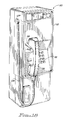
- Figure 18 is a perspective view of a public telephone housing and handset of the type more common in Europe and with which the present application is more particularly concerned. This comprises an elbow junction between the handset cable and the telephone housing.
- Figure 19 is a side view, partially cut away, of the elbow junction and a portion of the side surface of the telephone housing shown in Figure 18.
- Figure 20 is a rear elevation of the elbowjunction of Figure 19, illustrating the manner in which the cable stop and the restraint cable are fitted in a parallel fashion in the elbow junction in accordance with the precepts of this invention.
- Figure 21 is a side view, partially cut away, of the elbow junction and restraint cable arrangement shown in Figure 20.
- Referring first of all to the anchoring of armoured cord into the handset, a typical public telephone of the type used in the U.S.A., referred to generally by the
reference numeral 10, includes atelephone housing 12 having asurface 14 to which adial 16 andhandset cradle 18 are attached. Conventionally, thepublic telephone 10 includes a coin opening 20, acoin box 22 and acoin return 24. - The
public telephone 10 further includes ahandset 26 which is electronically and mechanically connected to thehousing 12 via an armoured cord andrestraint cable assembly 28. As shown in Figure 2, the armoured cord andrestraint cable assembly 28 includes an outerarmoured sheath 40, multipleelectrical wires 42 and arestraint cable 41. Typically, a cable stop 43 (see Figure 3) of substantially greater diameter than therestraint cable 41 is attached to the extremity of the restraint cable in thehandset 26. - Referring now specifically to Figures 2 to 5, the
handset 26 includes areceiver end 30, atransmitter end 32 and a hand-grip portion 34 (the hand-grip portion is sometimes referred to as the "yoke"). The hand-grip portion 34 is defined by fourperipheral sidewalls electronic wires 42 and therestraint cable 41 extend. Thehandset 26 is usually fabricated from a moulded plastic, with the covers for thereceiver 30 andtransmitter 32 being threaded on to the respective ends, as shown bythreads 31 in Figure 2. - A removable
restraint cable anchor 44 is fitted into the hand-grip portion 34 of thehandset 26 and between the receiver and transmitter ends 30, 32. It is preferred that theremovable anchor 44 be positioned along the hand-grip portion 34 away from the thin gaugedportion 33 of thesidewall 35 which curves into thereceiver end 30. One or more of theperipheral sidewalls 35 to 38 of the hand-grip portion 34 are provided with means for restraining the anchor44 against movement through the hand-grip portion 34 toward thetransmitter end 32. In the arrangement of Figures 2 to 5, this is achieved using asingle ledge 39 along the insideperipheral sidewall 35. It is also noted that further strengthening can be achieved by the thickening of thatsidewall 35. It will of course be appreciated that the positioning of theremovable anchor 44 along the hand-grip portion 34 and the use of theledge 39 causes pulling forces exerted upon the armoured cord andrestraint cable assembly 28, including therestraint cable 41, to be transmitted as a shear force downwardly along the insideperipheral sidewall 35, as opposed to being transmitted through thethinned portion 33 of thesidewall 35 that curves into thereceiver end 30. Accordingly, the peripheral sidewall arrangement shown in Figure 2 permits extremely high longitudinal forces to be applied to therestraint cable 41 without breaking the plastic materials that are normally used in the fabrication of thehandset 26. The thickening of the insideperipheral sidewall 35 at theledge 39 contributes to an even greater strengthening against such longitudinal pulling along therestraint cable 41. - Details of the
removable anchor 44 are illustrated in Figures 3 to 5. There, it is seen that one form of therestraint anchor 44 includes afirst slot 46 along the rear for receiving theelectrical wires 42 that pass along the hand-grip portion 34 to the receiver end 30 (also note Figure 2). Asecond slot 48 extends centrally into theremovable anchor 44 and into acentral opening 50 which is dimensioned to receive thecable stop 43 attached to the end of therestraint cable 41. The restraint cable may be easily slipped through the slot48 and extended downwardly toward the transmitter end so that thecable stop 43 engages into the opening 50. - A second form of a
removable anchor 54 is shown in Figures 6 and 7. Theremovable anchor 54 includes aslot 56 for receiving theelectrical wires 42, and alongitudinal hole 58 communicating with anopening 60, theopening 60 dimensioned to receive thecable stop 43. Theanchor 54 is thus essentially identical to theanchor 44 of Figures 3 to 5, except that a portion of theslot 48 is omitted. - Another form of a
removable anchor 64 is shown in Figures 8 and 9. Theanchor 64 has a protrusion orledge 65 along thefront surface 67 of theanchor 64. Theperipheral sidewall 35A of the hand-grip portion 34 in the form of Figure 8 includes a corresponding ledge orprotrusion 63 which mates with the protrusion orledge 65 along thefront surface 67 of theanchor 64. - As shown in Figure 9, the
anchor 64 also includes aslot 66 for receiving theelectrical wires 42 passing along to thereceiver end 30 of the handset, and aslot 68 and opening 70 for receiving therestraint cable 42 and thecable stop 43. - As described above and shown in Figure 2, the
ledge 39 is moulded along theinner sidewall 35 of thehandgrip portion 34. Other suitable ledge arrangements are shown in Figures 10 to 12. In Figure 10, a pair ofledges 72 may be placed on the inside of the opposing of inner andouter sidewalls ledges 74 are moulded along thesidewalls corner ledges 76 are moulded betweenadjacent sidewalls 35 to 38. The ledges shown in Figures 10 to 12 are positioned along an intermediate portion of the internal passageway of the hand-grip portion 34 defined by thesidewalls 35 to 38, in order to engage the particular form of theremovable anchor - Another form of the removable anchor is shown and described with reference to Figures 13 to 15. In this arrangement, the anchor, referred to generally by the
reference numeral 80, is supported by aledge 82 somewhat below thecurvature 84 of the receiver end of the handset. Like the arrangement of Figure 3, theanchor 80 includes afirst slot 86 for receiving thewires 42, and asecond slot 88 dimensioned to receive therestraint cable 41, so as to be engaged in anopening 90. A similar form of the invention is shown in Figures 16 and 17, and is identified by thereference numeral 92. This arrangement includes afirst slot 94 for receiving the wires, asecond slot 96 for receiving the restraint cable, and anopening 98 for receiving the restraint cable stop. - It will thus be appreciated that any ledge, protrusion or thickened wall portion along any sidewall (or between sidewalls) of the hand-grip portion of the telephone may likewise have a mating relationship with any protrusion or ledge along any corresponding wall of the removable anchor.
- A form of the telephone housing anchoring system and method in accordance with the present invention will now be described with reference to Figures 18 to 21.
- As shown in Figure 18, a conventional
public telephone 110 of the type used in Europe, has ahousing 112 and aside surface 114 to which is attached anelbow 127. Thetelephone 110 also includes akey pad 116, ahandset cradle 118 and an armoured telephone cord andrestraint cable assembly 128 essentially identical to theassembly 28 shown and described with reference to Figures 1 to 3. It will of course be observed that the end of the telephone cord andrestraint cable assembly 128 in Figure 18 differs significantly from the arrangement of Figure 1; in the arrangement of Figure 18, theassembly 128 at the housing passes into theelbow 127 along the sidewall 113 of thehousing 112, whereas in the arrangement of Figure 1, theassembly 28 extends into afront plate 14 of thehousing 12. The use of "elbow junction" public telephone housing arrangements like that shown in Figure 18 is particularly prevalent in European and other foreign countries, although some use of public telephones of that type is also made in the United States. However, many "elbow junction" public telephones presently in use have armoured handset cords without restraint cables, and do not have means for easily retrofitting an armoured telephone cord and restraint cable assembly of the type discussed above. - The arrangement shown and described next with reference to Figures 19 to 21 permits the easy and rapid retrofitting of the
elbow junction 127 of thepublic telephone 110 so as to utilise the armoured telephone cord andrestraint cable assembly 128. - Referring now to Figures 19 to 21, the
elbow 127 is fabricated from a generally flatcylindrical body portion 129 having a pair ofprongs sidewall 114 of thetelephone housing 112. The prongs include acircular groove 136 into which is inserted a C-ring 138 for locking the prongs inside thesidewall 114, much in the manner of the C-ring 175 in Figure 7 of the above described Drexler et al patent. - The
body 129 of theelbow 127 includes alateral opening 139 dimensioned to receive the armoured sheath portion of theassembly 128, with therestraint cable 141 extending across the central portion of the body to acable stop 143. Thebody 129 of theelbow 127 includes a pair of lockingtabs 142 which extend into the space between thecable stop 143 and the end of the armoured sheath of theassembly 128, forming alocking opening 146 for thecable stop 143. As shown in Figure 21, theelectrical wires 148 then extend out of theassembly 128, at a right angle through thebody 129 and then into thehousing 112 of thetelephone 110 shown in Figure 18. It will thus be appreciated by those skilled in the art that theelbow 127 may be easily retrofitted onto an existing public telephone of the type shown in Figure 18, by simply removing the existing elbow and then retrofitting theelbow 127 with an armoured telephone cord andrestraint cable assembly 128 in place, with theelbow 127 holding thearmoured cord 128 and thecable stop 143 in place. - Thus the present invention provides a particularly simple, but effective method of adapting telephone housings of the type described, i.e. comprising an elbow joint for entry of the cord into the housing, for use with telephones employing an armoured cord connecting the handset to the telephone housing, and more particularly for anchoring the cord to the housing.
Claims (10)
1. A public telephone and handset assembly of the kind comprising a telephone housing (112), an armoured cord (128) connecting the housing to the handset (126), the armoured cord comprising a high tensile strength restraint cable (141) anchored at one end to the handset and at the other to the housing, the armoured cord (128), or at least the electronic leads (148) contained therein, passing into the housing (112) via an elbow junction (127) affixed to a face (114) of the housing (112) characterised in that the restraint cable (141) is anchored in the elbow junction (127) externally of the housing (112).
2. A public telephone and handset assembly according to claim 1, characterised in that the restraint cable (141) is anchored in the elbow junction (127) by means of a stop (143) attached to the end of the restraint cable (141), the diameter of the stop (143) being greater than that of the restraint cable, the said stop (143) engaging against opposed abutment surfaces (142) provided in the elbow junction (127) and located on opposite sides of the restraint cable (141), the spacing between the opposed abutment surfaces (142) being greater than the diameter of the restraint cable (141) but less than that of the stop (143).
3. A public telephone and handset assembly according to claim 2, characterised in that the abutment surfaces (142) extend generally perpendicular to the face (114) of the housing (112) to which the elbow junction (127) is attached whereby tensile forces applied to the armoured cord are applied to the abutment surfaces (142) in a direction that is substantially parallel to the surface of the telephone housing.
4. A public telephone and handset assembly according to claim 1, 2, or 3, characterised in that the elbow junction (127) is detachably mounted to the telephone housing (112).
5. A public telephone and handset assembly according to claim 4, characterised in that the elbow junction (127) comprises a pair of rearwardly extending prongs (132, 134) extending into a preformed aperture in the housing (112) and secured therein by a locking ring or clip (138) engaging those prongs interiorily of the housing (112).
6. A public telephone and handset assembly according to any one of claims 1 to 5, characterised in that the handset (26) is of the type comprising a hollow moulding mounting a transmitter (32) at one end and a receiver (30) at the other with a hollow hand-grip (34) in between, and wherein the armoured cord (28) is received into the handset from one end and anchored therein within the hand-grip portion (34) of the handset (26).
7. A public telephone and handset assembly according to claim 6, characterised in that the armoured cord (28) is anchored within the hand- grip position (34) of the handset (26) by means of a stop (43) secured to the end of the restraint cable (41), said stop having a diameter that is greater than that of the restraint cable and which engages with a removable anchor member (44) positioned within the hand-grip portion (34) of the handset and restrained against longitudinal movement therein arising from tension applied to the armoured cord by means of abutment surfaces (39) situated inside the hand-grip portion (34) of the handset (26).
8. A public telephone and handset assembly according to claim 6, characterised in that the anchor member (44) comprises a longitudinal slot (88) or passageway (96) therein which accommodates restraint cable (41), that slot (88) or passageway (96) communicating with a recess (70, 98) in the end of the anchor member (44) which accommodates the stop (43) attached to the end of the restraint cable (41).
9. A public telephone and handset assembly according to claim 8, characterised in that the anchor member (44) comprises an additional longitudinal slot or passageway (86, 94) to accommodate the electronic wires (42) leading from the armoured cord through the hand-grip portion (34) of the handset (26) to either the receiver (30) or the transmitter (32).
10. A public telephone and handset assembly according to any one of claims 7 to 9, wherein the anchor member (44) is constrained from longitudinal movement within the hand-grip portion (34) of the handset (26) by one or more ledges (39) positioned within and integral with the moulding of the hand-grip portion of the handset.
Applications Claiming Priority (2)
| Application Number | Priority Date | Filing Date | Title |
|---|---|---|---|
| US572152 | 1984-01-19 | ||
| US07/572,152 US5136635A (en) | 1990-08-23 | 1990-08-23 | Apparatus and method for securing an armored cord and restraint cable assembly to a telephone handset and housing |
Publications (2)
| Publication Number | Publication Date |
|---|---|
| EP0473381A2 true EP0473381A2 (en) | 1992-03-04 |
| EP0473381A3 EP0473381A3 (en) | 1992-06-03 |
Family
ID=24286568
Family Applications (1)
| Application Number | Title | Priority Date | Filing Date |
|---|---|---|---|
| EP19910307800 Withdrawn EP0473381A3 (en) | 1990-08-23 | 1991-08-23 | Apparatus and method for securing an armoured cord and restraint cable assembly to a telephone handset and housing |
Country Status (2)
| Country | Link |
|---|---|
| US (1) | US5136635A (en) |
| EP (1) | EP0473381A3 (en) |
Cited By (2)
| Publication number | Priority date | Publication date | Assignee | Title |
|---|---|---|---|---|
| WO1995020856A1 (en) * | 1994-01-31 | 1995-08-03 | Hosiden Besson Limited | Cable connectors for telephone handsets |
| WO2004004290A1 (en) * | 2002-06-29 | 2004-01-08 | Ritto Gmbh & Co. Kg | Wall telephone with hanging handset |
Families Citing this family (2)
| Publication number | Priority date | Publication date | Assignee | Title |
|---|---|---|---|---|
| US5577119A (en) * | 1995-05-08 | 1996-11-19 | I.D. Tel Corp. | Tension resisting bracket for telephone handsets |
| US8537012B2 (en) * | 2009-09-23 | 2013-09-17 | Checkpoint Systems, Inc. | Display assembly with cable stop |
Citations (5)
| Publication number | Priority date | Publication date | Assignee | Title |
|---|---|---|---|---|
| FR2186790A1 (en) * | 1972-06-02 | 1974-01-11 | Tamura Electric Works Ltd | |
| US4518830A (en) * | 1982-06-25 | 1985-05-21 | At&T Bell Laboratories | Armored telephone cord with a longitudinal strength member |
| EP0251238A2 (en) * | 1986-06-26 | 1988-01-07 | Nynex Corporation | Armored cord handset |
| EP0326734A2 (en) * | 1988-02-05 | 1989-08-09 | Raymond Arzounian | Apparatus for anchoring a telephone handset to a telephone housing |
| JPH01258535A (en) * | 1988-04-08 | 1989-10-16 | Toshiba Corp | Telephone set |
Family Cites Families (1)
| Publication number | Priority date | Publication date | Assignee | Title |
|---|---|---|---|---|
| US4974258A (en) * | 1989-07-21 | 1990-11-27 | Raytel, Inc. | Vandal-proof handset for a pay telephone |
-
1990
- 1990-08-23 US US07/572,152 patent/US5136635A/en not_active Expired - Lifetime
-
1991
- 1991-08-23 EP EP19910307800 patent/EP0473381A3/en not_active Withdrawn
Patent Citations (5)
| Publication number | Priority date | Publication date | Assignee | Title |
|---|---|---|---|---|
| FR2186790A1 (en) * | 1972-06-02 | 1974-01-11 | Tamura Electric Works Ltd | |
| US4518830A (en) * | 1982-06-25 | 1985-05-21 | At&T Bell Laboratories | Armored telephone cord with a longitudinal strength member |
| EP0251238A2 (en) * | 1986-06-26 | 1988-01-07 | Nynex Corporation | Armored cord handset |
| EP0326734A2 (en) * | 1988-02-05 | 1989-08-09 | Raymond Arzounian | Apparatus for anchoring a telephone handset to a telephone housing |
| JPH01258535A (en) * | 1988-04-08 | 1989-10-16 | Toshiba Corp | Telephone set |
Non-Patent Citations (1)
| Title |
|---|
| PATENT ABSTRACTS OF JAPAN vol. 14, no. 16 (E-872)(3959) 12 January 1990 & JP-A-1 258 535 ( TOSHIBA CORP. ) * |
Cited By (4)
| Publication number | Priority date | Publication date | Assignee | Title |
|---|---|---|---|---|
| WO1995020856A1 (en) * | 1994-01-31 | 1995-08-03 | Hosiden Besson Limited | Cable connectors for telephone handsets |
| GB2293055A (en) * | 1994-01-31 | 1996-03-13 | Hosiden Besson Ltd | Cable connectors for telephone handsets |
| GB2293055B (en) * | 1994-01-31 | 1997-12-10 | Hosiden Besson Ltd | Cable connectors for telephone handsets |
| WO2004004290A1 (en) * | 2002-06-29 | 2004-01-08 | Ritto Gmbh & Co. Kg | Wall telephone with hanging handset |
Also Published As
| Publication number | Publication date |
|---|---|
| EP0473381A3 (en) | 1992-06-03 |
| US5136635A (en) | 1992-08-04 |
Similar Documents
| Publication | Publication Date | Title |
|---|---|---|
| US6396993B1 (en) | Optical fiber breakaway apparatus and method | |
| KR100245143B1 (en) | Anti-snag duplex connector | |
| CA1293877C (en) | Connector for optical fiber cable | |
| US6266469B1 (en) | Fiber optic cable pulling device | |
| EP1186925A1 (en) | Optical fiber guide device | |
| KR19980703324A (en) | Fiber optic splice structure | |
| CA1195743A (en) | Armored telephone cord with a longitudinal strength member | |
| US20050254768A1 (en) | Drop wire clamp | |
| GB2193902A (en) | Climbing aids | |
| EP1373954B1 (en) | Cable termination device | |
| JPH04363007A (en) | Signal discriminator | |
| AU2002242836A1 (en) | Cable termination device | |
| EP0473381A2 (en) | Apparatus and method for securing an armoured cord and restraint cable assembly to a telephone handset and housing | |
| US6269213B1 (en) | Optical transmission device with optical fiber cable accommodating structures | |
| US20050218269A1 (en) | Clamp | |
| MY124484A (en) | Ribbon cable connector assembly | |
| EP3620835B1 (en) | Cable-retention device | |
| EP0961363B1 (en) | Bolted type connector | |
| KR910000844B1 (en) | Armored cord handset | |
| EP1556925B1 (en) | Cable connector assembly and system | |
| EP0709925B1 (en) | Improved receptacle housing for connector assembly | |
| JPH0440906B2 (en) | ||
| JPH0722761A (en) | Strain relieving device and usage thereof | |
| JPH10133030A (en) | Storage case for optical cable connection | |
| WO2011073259A1 (en) | Cable connector |
Legal Events
| Date | Code | Title | Description |
|---|---|---|---|
| PUAI | Public reference made under article 153(3) epc to a published international application that has entered the european phase |
Free format text: ORIGINAL CODE: 0009012 |
|
| AK | Designated contracting states |
Kind code of ref document: A2 Designated state(s): CH DE FR GB LI |
|
| PUAL | Search report despatched |
Free format text: ORIGINAL CODE: 0009013 |
|
| AK | Designated contracting states |
Kind code of ref document: A3 Designated state(s): CH DE FR GB LI |
|
| STAA | Information on the status of an ep patent application or granted ep patent |
Free format text: STATUS: THE APPLICATION IS DEEMED TO BE WITHDRAWN |
|
| 18D | Application deemed to be withdrawn |
Effective date: 19930215 |