EP0473156B1 - Electrostatic coating facility for electroconductive coating material - Google Patents
Electrostatic coating facility for electroconductive coating material Download PDFInfo
- Publication number
- EP0473156B1 EP0473156B1 EP91114543A EP91114543A EP0473156B1 EP 0473156 B1 EP0473156 B1 EP 0473156B1 EP 91114543 A EP91114543 A EP 91114543A EP 91114543 A EP91114543 A EP 91114543A EP 0473156 B1 EP0473156 B1 EP 0473156B1
- Authority
- EP
- European Patent Office
- Prior art keywords
- conveyer
- insulated
- relay
- transfer device
- entering
- Prior art date
- Legal status (The legal status is an assumption and is not a legal conclusion. Google has not performed a legal analysis and makes no representation as to the accuracy of the status listed.)
- Expired - Lifetime
Links
- 239000011248 coating agent Substances 0.000 title claims description 95
- 238000000576 coating method Methods 0.000 title claims description 95
- 238000009503 electrostatic coating Methods 0.000 title claims description 32
- 239000000463 material Substances 0.000 title claims description 25
- 238000009413 insulation Methods 0.000 claims description 47
- 230000007935 neutral effect Effects 0.000 claims description 4
- 230000003247 decreasing effect Effects 0.000 claims description 2
- 230000005684 electric field Effects 0.000 description 7
- 230000000694 effects Effects 0.000 description 6
- 239000002245 particle Substances 0.000 description 5
- 239000007921 spray Substances 0.000 description 5
- 230000015556 catabolic process Effects 0.000 description 3
- 238000006731 degradation reaction Methods 0.000 description 3
- 230000003068 static effect Effects 0.000 description 3
- 238000005299 abrasion Methods 0.000 description 2
- 238000010586 diagram Methods 0.000 description 2
- 230000005686 electrostatic field Effects 0.000 description 2
- 239000012212 insulator Substances 0.000 description 2
- 239000011347 resin Substances 0.000 description 2
- 229920005989 resin Polymers 0.000 description 2
- 229910000831 Steel Inorganic materials 0.000 description 1
- 230000008602 contraction Effects 0.000 description 1
- 230000002939 deleterious effect Effects 0.000 description 1
- 238000009499 grossing Methods 0.000 description 1
- 238000009434 installation Methods 0.000 description 1
- 238000000034 method Methods 0.000 description 1
- 239000003960 organic solvent Substances 0.000 description 1
- 238000002360 preparation method Methods 0.000 description 1
- 238000005507 spraying Methods 0.000 description 1
- 239000010959 steel Substances 0.000 description 1
- 238000006467 substitution reaction Methods 0.000 description 1
Images



Classifications
-
- B—PERFORMING OPERATIONS; TRANSPORTING
- B05—SPRAYING OR ATOMISING IN GENERAL; APPLYING FLUENT MATERIALS TO SURFACES, IN GENERAL
- B05B—SPRAYING APPARATUS; ATOMISING APPARATUS; NOZZLES
- B05B5/00—Electrostatic spraying apparatus; Spraying apparatus with means for charging the spray electrically; Apparatus for spraying liquids or other fluent materials by other electric means
- B05B5/08—Plant for applying liquids or other fluent materials to objects
- B05B5/082—Plant for applying liquids or other fluent materials to objects characterised by means for supporting, holding or conveying the objects
- B05B5/084—Plant for applying liquids or other fluent materials to objects characterised by means for supporting, holding or conveying the objects the objects lying on, or being supported above conveying means, e.g. conveyor belts
Definitions
- the present invention concerns an electrostatic coating facility for applying an electroconductive coating material comprising a coating machine disposed in a coating zone while being grounded to the earth, an insulated conveyer disposed in said coating zone for conveying an object to be coated in an electrically insulated state, an entering conveyer disposed for carrying the object to be coated into said coating zone, and a delivery conveyer for carrying the coated object after coating out of said coating zone.
- An electrostatic coating facility in which the coating machine is grounded to the earth and the objects to be coated are applied with a high voltage while being conveyed in an electrically insulated state is particularly advantageous for multicolor coating with aqueous coating materials, since insulating supply pipes, reservoirs, etc. for each coating material or insulative resin coating materials that consume a great amount of deleterious organic solvents are avoided.
- An electrostatic coating facility of the above-mentioned kind is known from the document EP-A-0 308 142.
- a hanger-type conveyer is provided between the entering conveyer and the delivery conveyer.
- each hanger rod of the conveyer includes an insulator element.
- a clamp device for clamping the object in preparation of the spraying procedure. Upon this clamping, the insulated object is impressed with a high voltage transmitted by the clamping device.
- an object of the present invention to prevent the high voltage applied to the objects to be conveyed from leaking through the conveyer when such objects are conveyed continuously by way of the conveyer.
- the foregoing object of the present invention can be attained by an electrostatic coating facility of the initially mentioned kind wherein the insulated conveyer serves to apply a high voltage to the object to be coated, and a relay transfer device is interposed between said insulated conveyer and said entering conveyer, and between said insulated conveyer and said delivery conveyer for transferring the object in an electrically insulated state while keeping a required insulation distance between it and each of the conveyers.
- an object to be coated carried into by the entering conveyer is transferred by the relay transfer device interposed between the entering conveyer and the insulated conveyer in the electrically insulated state from the entering conveyer to the insulated conveyer disposed in the coating zone, while keeping a required insulation distance between both of the conveyers.
- the object to be coated transferred to the insulated conveyer is applied with a high voltage to form a static electric field between it and the coating machine disposed in the coating zone while being grounded to the earth and coating particles sprayed from the coating machine are attracted and adsorbed onto the object under the effect of the electric field.
- the relay transfer device comprises an insulated truck running reciprocally between the insulated conveyer and the entering conveyer or between the insulated conveyer and the delivery conveyer, and a relay conveyer mounted on said insulated truck for transferring the object to be coated.
- the relay transfer device comprises an insulation stand secured at a position between the insulated conveyer and the entering conveyer or between the insulated conveyer and the delivery conveyer, and a relay conveyer for transferring the object to be coated and a sliding device for reciprocally moving said relay conveyer between the insulated conveyer and the entering conveyer or between the insulated conveyer and the delivery conveyer mounted on said insulation stand.
- the relay transfer device comprises an insulated relay conveyer disposed at a predetermined insulation distance relative to said insulated conveyer, a conveyer rail of said insulated conveyer, relay rails disposed on both ends of said conveyer rail and bridging devices for advancing and retracting said relay rails relative to a conveyer rail of the insulated conveyer disposed in the coating zone, and to a conveyer rail of the entering conveyer or the delivery conveyer, respectively.
- a relay device disposed for applying a high voltage to said relay transfer device forwarding to the side of said insulated conveyer and connecting the relay transfer device forwarding to the side of said entering conveyer or to the side of the delivery conveyer to the ground, a high voltage generator and a circuit for connecting said high voltage generator with said relay transfer device, in which said circuit comprises a main switch and an auxiliary switch disposed in parallel, said main switch comprising a neutral position is adapted to be switched between the contact on the side of said high voltage generator and the contact on the side of the ground and said auxiliary switch is adapted to be switched between the contact on the side of said high voltage generator and the contact on the side of the ground by way of a resistor having a high resistance value.
- a voltage controller disposed for gradually increasing a voltage applied to said relay transfer device forwarding from the side of said entering conveyer or the side of said delivery conveyer toward the side of said insulated conveyer into an identical potential with that of said insulated conveyer and gradually decreasing the voltage applied to said relay transfer device forwarding from the side of said insulated conveyer to the side of said entering conveyer or the side of said delivery conveyer to the grounding potential.
- the voltage controller comprises a linear resistor having a high resistance value and a contact member disposed on said resistor, with both ends of which being electrically connected to the side of the ground and the high voltage respectively, and the contact member being electrically connected with said relay transfer device.
- FIG. 1 is a front elevational view illustrating a first embodiment of an electrostatic coating facility according to the present invention.
- an insulated conveyer 1 is arranged along a coating zone in which a coating machine is disposed while being grounded to the earth.
- the insulated conveyer 1 serves to apply a high DC voltage of about 80 to 120 KV to a car body W as an object to be coated.
- the insulated conveyer 1 comprises insulation supports 2 and 2 each standing vertically at a predetermined distance along the coating Zone, a frame 3 supported horizontally between them, a pair of sprockets 4a and 4b disposed at both front and rear ends of the frame 3, and an endless chain 5 laid horizontally between both of the sprockets 4a and 4b, so that a conveyer truck 6 carrying the car body W thereon is trailed and caused to run along a conveyer rail 7 disposed along the upper end of the frame 3.
- a high voltage cable 9 from a high voltage generator 8 is connected to the conveyer rail 7 or the frame 3, so that a high voltage is applied from the conveyer rail 7 by way of the conveyer truck 6 to the car body W.
- An entering conveyer 10 for carrying the car body W into the coating zone and a delivery conveyer 11 for carrying the car body W out of the coating zone are disposed, and a relay transfer device 12 is interposed between the conveyers 10 and 11 for transferring the car body W in an electrically insulated state while keeping a required insulation distance between it and each of conveyers.
- the relay transfer device 12 comprises an insulated truck 13 that reciprocates between the insulated conveyer 1 and the entering conveyer 10 or the delivery conveyer 11, and a relay conveyer 14 mounted on the insulated truck 13 for transferring the car body W carried on the conveyer truck 6.
- the insulated truck 13 is adapted to run reciprocally at a predetermined stroke on a conveyer rail 16 of a floor conveyer 15 laid between the insulated conveyer 1 and the entering conveyer 10 or the delivery conveyer 11.
- a relay conveyer 14 and its conveyer rail 19 are disposed on a frame 18 supported horizontally on each of a plurality of insulation supports 17, 17 ---.
- a pair of sprockets 20a and 20b are disposed at both front and rear ends of the frame 18 and an endless chain 21 is laid in parallel between them for trailing the conveyer truck 6.
- the chain 21 is driven intermittently in one direction by a motor 22 mounted on the frame 18, so that the conveyer truck 6 carrying the car body W is transferred from a conveyer rail 23 on the entering conveyer 10 by way of the conveyer rail 19 to the conveyer rail 7 on the insulated conveyer 1 or from the conveyer rail 7 on the insulated conveyer 1 by way of the conveyer rail 19 on the relay conveyer 14 to a conveyer rail 24 on the delivery conveyer 11.
- a relay device 25 is disposed for switchingly connecting a high voltage cable 26 connected to the conveyer rail 19 or the frame 18 of each relay conveyer 14 between the high voltage generator 8 and the ground G.
- the relay conveyer 14 is stopped and, in turn, the floor conveyer 15 is actuated, and the insulated truck 13 of the relay transfer device 12 is caused to run from the entering conveyer 10 to the insulated conveyer 1 along the conveyer rail 16 on the floor conveyer 15.
- the car body W mounted together with the conveyer truck 6 on the relay transfer device 12 is transferred electrically insulated state, to the insulated conveyer 1 applied with a high voltage, with a required insulation distance being kept between insulated conveyer 1 and the entering conveyer 10.
- the relay device 25 switchingly connects the high voltage cable 26 from the side of the ground G to the side of the high voltage generator 8 to apply a high voltage to the relay conveyer 14 and the car body W carried on the conveyer rail 19.
- the floor conveyer 15 is stopped and, in turn, the relay conveyer 14 mounted on the insulation truck 13 is actuated again, by which the conveyer truck 6 on the conveyer rail 19 of the conveyer 14 is trailed by the chain 21 and moved to the conveyer rail 7 of the insulated conveyer 1.
- the relay conveyer 14 is stopped and, in turn, the floor conveyer 15 is actuated in the direction opposite to the above, by which the insulated truck 13 starts running from the insulated conveyer 1 to the entering conveyer 10 and, in the course of the running, the relay device 25 is actuated to switchingly connect the high voltage cable 26 connected to the relay conveyer 14 from the side of the high voltage generator 6 to the side of the ground, to thereby discharge residual electric charges on the relay conveyer 14.
- the relay transfer device 12 returns to the terminal end of the conveyer rail 23 of the entering conveyer 10 without causing spark discharge between them and then stands by again on that side.
- the conveyer truck 6 transferred by the relay transfer device 12 to the insulated conveyer 1 is trailed by the chain 5 and caused to run on the conveyer rail 7 applied with the high voltage.
- the car body W carried on the conveyer truck 6 is conveyed in an electrically insulated state along the coating zone in which the insulated conveyer 1 is disposed and, at the same time, applied with the high voltage from the conveyer rail 7 by way of the conveyer truck 6 to form a static electric field between it and the coating machine disposed in a state grounded to the earth in the coating zone.
- coating particles sprayed from the coating machine are attracted and adsorbed on the surface of the car body W under the effect of the electric field.
- the car body W completed with the electrostatic coating is conveyed by way of the insulated conveyer 1 to the terminal end of the conveyer rail 7 and then transferred by the relay transfer device 12 that has stood by the side of the terminal end to the delivery conveyer 11 in an electrically insulated state, with a required insulation distance being kept between the insulated conveyer 1 and the delivery conveyer 11.
- electrostatic coating can be applied while continuously conveying successive car bodies W.
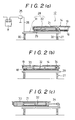
- the relay transfer device 12 illustrated in Fig. 1 is entirely reciprocated between the insulated conveyer 1 and the entering conveyer 10 or the delivery conveyer 11, but the present invention is not restricted only to such a constitution but, in a modified embodiment, only the relay conveyer 14 may be reciprocated as shown in Fig. 2(a), (b) and (c).
- FIG. 2(a), (b) and (c) show a front elevational view for the modified embodiment and the operation of the relay transfer device 12, in which an insulation stand 27 is secured at an intermediate position between the insulated conveyer 1 and the entering conveyer 10 or the delivery conveyer 11.
- a relay conveyer 14 and a sliding device 28 for reciprocally moving the relay conveyer 14 between the insulated conveyer 1 and the entering conveyer 10 or the delivery conveyer 11 are mounted on the insulation stand 27.
- the insulation stand 27 comprises a table 29 carrying the relay conveyer 14 and the sliding device 28 thereon and a plurality of insulation supports 30, 30 --- that support the table 29.
- the sliding device 28 comprises a slide rail 31 laid on the table 29 and a double head cylinder 32 for reciprocally driving a frame 18 of the relay conveyer 14 slidably supported along a slide rail 31.
- the double head cylinder 32 has a piston rod 33 secured on the side of the frame 18 and another piston rod 34 secured on the side of the table 29.
- the relay conveyer 14 trails by its chain 21 the conveyer truck 6 and transfers it from the conveyer rail 23 on the entering conveyer 10 to the conveyer rail 19 on the relay conveyer 14.
- the relay conveyer 14 again trails the conveyer truck 6 on the conveyer rail 16 by the chain 21 and transfers it to the conveyer rail 7 of the insulated conveyer 1.
- the insulated conveyer 1 is such a short conveyer as conveying the car body W only one by one, occurrence of spark discharge can be prevented also by switchingly connecting the high voltage cable 9 connected to the insulated conveyer 1 between the high voltage generator 8 and the ground, so that the insulated conveyer 1 is grounded to the earth only when the car body W is transferred between the relay conveyer 14 and the insulated conveyer 1.
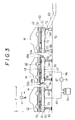
- Fig. 3 is a front elevational view illustrating a second embodiment of an electrostatic coating facility according to the present invention
- Fig. 4 is a side elevational view of a relay transfer device used for the facility
- Fig. 5 is a perspective view illustrating a principal portion of the relay transfer device
- Figs. 6(a), (b), (c) are schematic views illustrating the operation of the relay transfer device
- Fig. 7 is a perspective view for a principal portion of a modified embodiment of the relay transfer device.
- an insulated conveyer 43 is arranged in a coating zone Z, in which a coating machine 41 is disposed while being grounded to the earth.
- the insulated conveyer 43 is adapted to convey a car body W as an object to be coated carried on a conveyer truck 42 in an electrically insulated state and applying a high voltage to the car body W.
- a relay transfer device 46 is interposed between the insulated conveyer 43 and an entering conveyer 44 for carrying the car body W into the coating zone Z and between the insulated conveyer 43 and a delivery conveyer 45 for carrying the car body W out of the coating zone Z.
- the relay transfer device 46 is adapted to transfer the car body W in an electrically insulated state while keeping a required insulation distance between each of the conveyers.
- Each of the relay transfer devices 46 comprises an insulated relay conveyer 47 disposed between the insulated conveyor 43 and the entering conveyer 44 or the delivery conveyer 45 at a predetermined insulation distance, right and left conveyer rails 48 and 48 of the insulated conveyer 47, relay rails 49a and 49b stacked slidably on both ends of the relay rails and bridging devices 53a and 53b for protruding and retracting each of the relay rails 49a and 49b relative to the right and left conveyer rails 50 of the insulated conveyer 43 and the right and left conveyer rails 51 of the entering conveyer 44 or the right and left conveyer rails 52 of the delivery conveyer 45 respectively.
- the insulated relay conveyer 47 comprises a frame 55 supported by a plurality of insulation supports 54, 54, ---a pair of sprockets 46 and 46 disposed on both ends of the frame 55 and an endless chain 57 laid in parallel between the sprockets for trailing the conveyer truck 42 carrying the car body W.
- Each of the relay rails 49a and 49b disposed on both sides of the conveyer rail 48 is constituted with C-shaped steel material slidably inserted along the inside of the conveyer rail 48 on which wheels 58 of the conveyer truck 42 are caused to run.
- Each of the bridging devices 53a and 53b comprises an air cylinder S fixed at its base to the frame 55 and at its rod head to each of the relay rails 49a and 49b, so that each of the relay rails 49a and 49b is protruded or retracted by the extension and contraction of the piston rod 59 of the cylinder S.
- the insulated conveyer 43 comprises a frame 61 supported by a plurality of insulation supports 60, 60, ---at the same height as the frame 55 of the insulated relay conveyer 47, a pair of sprockets 62 and 62 disposed on both ends of the frame 61 and an endless chain 63 disposed in parallel between both of the sprockets 62 and 62 for trailing the conveyer truck 42.
- a high voltage cable 65 is connected to the insulated conveyer 43 for applying a high DC voltage of about 80 to 120 KV from a high voltage generator 64.
- a high voltage cable 66 connected to the insulated relay conveyer 47 is switchingly connected between the high voltage generator 66 and the ground by means of a relay device 67 interposed in the midway of the cable 66.
- Each of the entering conveyer 44 and the delivery conveyer 45 comprises a frame 70 supported vertically movably on a plurality of cylinders 68, 68, --- so as to be lifted from the height of a line conveyer 69 to the same height as that for the frame 55 of the insulated relay conveyer 47, a pair of sprockets 71 and 71 disposed on both ends of the frame 70 and an endless chain 72 laid in parallel between the sprockets 71 and 71 for trailing the conveyer 42.
- the entering conveyer 44 receives the conveyer truck 42 carrying a car body W from the line conveyer 69 laid along the coating line, in a state where the piston rods 73 for the respective cylinders 68, 68, ---that support the lack 70 is contracted as shown by the dotted chain in Fig. 6(c). Then, the conveyer 49 transfers the conveyer truck 42 onto the conveyer rail 51 of the entering conveyer 44.
- the bridging device 53a of the relay transfer device 46 is actuated to project the relay rail 49a from one end of the conveyer rail 48 of the insulated relay conveyer 47 to the side of the conveyer rail 51 of the entering conveyer 44, to bridge the conveyer rails 48 and 51 by the relay rail 49a.
- the entering conveyer 44 and the insulated relay conveyer 47 are actuated to transfer the conveyer truck 42 from the conveyer 51 of the entering conveyer 44 by way of the relay rail 49a to the conveyer rail 48 of the insulated relay conveyer 47.
- the relay rail 49a bridging the conveyer rail 51 of the entering conveyer 44 and the conveyer rail 48 is retracted to space apart the entering conveyer 44 and the insulated relay conveyer 47 by a predetermined insulation distance.
- the high voltage cable 66 connected to the insulated relay conveyer 47 is switchingly connected by the relay device 67 from the side of the ground to the side of the high voltage generator 66, to apply a high voltage to the insulated relay conveyer 47, as well as the conveyer truck 42 and the car body W now transferred on the conveyer rail 48.
- the bridging device 53b is actuated to project the rail 49b from the other end of the conveyer rail 48 of the insulated relay conveyer 47 to the side of the conveyer rail 50 of the insulated conveyer 43 disposed in the coating zone Z, to bridge the conveyer rails 48, 50 by the relay rail 49a.
- the insulated relay conveyer 47 and the insulated conveyer 43 are actuated to transfer the conveyer truck 42 from the conveyer rail 48 of the insulated relay conveyer 47 by way of the relay rail 49b to the conveyer rail 50 of the insulated conveyer 43.
- the relay rail 49b is retracted to space apart the insulated conveyer 43 and the insulated relay conveyer 47 by a predetermined insulation distance.
- the high voltage cable 66 connected to the insulated relay conveyer 47 is switchingly connected from the side of the high voltage generator 64 to the side of the ground by the relay device 67 to discharge the residual charges on the insulated relay conveyer 47.
- the car body W transferred together with the conveyer truck 42 to the insulated conveyer 43 and applied with the high voltage forms an electrostatic field between it and a coating machine 44 disposed in the state being grounded to the earth in the coating zone Z to attract and adsorb coating particles sprayed from the coating machine 41 under the effect of the electric field.
- electrostatic coating can be applied while continuously conveying objects to be coated one by one by each of the conveyers.
- the conveyer truck 42 carrying the car body W is transferred by way of the insulated relay conveyer 47 of the relay transfer device 46 to the delivery conveyer 45.
- the operation of the relay transfer device 46 in this embodiment is just opposite, in the sequence, to the operation of the relay transfer device 46 interposed between the insulation conveyer 43 and the entering conveyer 44 described previously and, accordingly, detailed descriptions will be omitted.
- the entering conveyer 44 and the delivery conveyer 45 are disposed independently of the line conveyer 69.
- the line conveyer 69 modified such that it is extended to the same height as that for the insulated relay conveyer 47 for each of the relay transfer devices 46 and may be used also as an entering conveyer or a delivery conveyer.
- the present invention also includes such a modified embodiment.
- relay rails 49a and 49b disposed on the conveyer rail 48 of the insulated relay conveyer 47 are stacked slidably on both ends of the conveyer rail 48 and protruded and retracted horizontally in this illustrated embodiment.
- the invention is not restricted only to such an embodiment, but the relay rails 49a (49b) may be connected to both ends of the conveyer rail 48 each by means of a hinge 80 and protruded and retracted vertically by the rotation for a predetermined angle by a cylinder S of the bridging devices 53a (53b) as shown in Fig. 7.
- the insulated relay conveyer 47 is switchingly connected between the high voltage generator 64 and the ground so that spark discharge is not caused between the insulated relay conveyer 47 and the insulated conveyer 43 or the entering conveyer 44 in this second embodiment as described above.
- the insulation conveyer 43 may be switchingly connected between the high voltage generator 64 and the ground upon transferring the conveyer truck 42 between the insulated relay conveyer 47 and the insulated conveyer 43.
- Fig. 8 is a circuit diagram for a relay device which is a principal portion of the third embodiment of an electrostatic coating facility according to the present invention.
- a relay device 25 in this embodiment is adapted to switchingly connect a high voltage cable 26 connected to the conveyer rail 19 or the frame 18 in each of the relay conveyers 14 between the high voltage generator 8 and the ground.
- a main switch 81 and an auxiliary switch 82 are disposed in parallel with each other, in which the contact B of the main switch 81 is connected with the high voltage generator 8, while the contact A is grounded to the earth.
- a neutral contact N is disposed between the contact A and the contact B.
- the auxiliary switch 82 is adapted to select a contact C and a contact D by way of a resistor 83 having a high resistance value set to about 1500 to 7000 M ohm, the contact C being connected with the high voltage generator 8, while the contact D being connected with the ground G.
- the relay conveyer 14 is stopped and, in turn, the floor conveyer 15 is actuated, by which the insulated truck 13 of the relay transfer device 12 is caused to run from the side of the entering conveyer 10 to the side of the insulated conveyer 1 along the conveyer rail 16 of the floor conveyer 15.
- the car body W carried together with the conveyor truck 6 in the relay transfer device 12 is conveyed in an electrically insulated state to the insulated conveyer 1 applied with a high voltage, with a required insulation distance being kept between the insulated conveyer 1 and the entering conveyer 10.
- the high voltage cable 26 of the relay device 25 is switchingly connected from the side of the ground G to the side of the high voltage generator 8, by which a high voltage is applied to the relay conveyer 14 and the car body W carried on the conveyer rail 19.
- the auxiliary switch 82 is at first switched from the contact D to the contact C and then the main switch 81 is connected to the contact B on the side of the high voltage generator 8. Then, since the voltage is gradually increased through the resistor 83 of high resistance value and the potential difference between each of the contacts is kept low by the voltage drop, spark discharge is not caused between each of the contacts upon switching each of the switches 81 and 82 and damages for each of the contacts or degradation of insulation oil or the like can be prevented.
- the relay conveyer 14 is stopped and, in turn, the floor conveyer 15 is actuated in the direction opposite to the above, by which the insulated truck 13 starts running from the side of the insulated conveyer 1 to the side of the entering conveyer 10 and, in the course of the running, the relay device 25 is actuated to switchingly connect the high voltage cable 26 connected to the relay conveyer 14 from the side of the high voltage generator 8 to the side of the ground G, to discharge residual electric charges on the relay conveyer 14.
- the relay transfer device 12 returns to the terminal end of the conveyer rail 23, without causing spark discharge between it and the entering conveyer 10, and stands-by again at that side.
- the conveyer truck 6 transferred by the relay transfer device 12 to the insulated conveyer 1 is trailed by the chain 5 and caused to run on the conveyer rail 7 applied with the high voltage.
- the car body W carried on the conveyer truck 6 is conveyed in an electrically insulated state along the coating zone in which the insulated conveyer 1 is disposed and, at the same time, applied with the high voltage by way of the conveyer truck 6 from the conveyer rail 7 and forms an electrostatic field between it and the coating machine disposed in the coating zone in a state grounded to the earth.
- coating particles sprayed from the coating machine are attracted and adsorbed on the surface of the car body W.
- the car body W after the completion of the electrostatic coating, is conveyed by the insulated conveyer 1 to the terminal end of the conveyer rail 7 and then transferred in an electrically insulated state to the delivery conveyer 11 by the relay transfer device 12 that has stood by on the side of the terminal end with keeping a predetermined insulation distance being kept between the insulated conveyer 1 and the delivery conveyer 11.
- the relay transfer device 12 is adapted to move reciprocally for its whole portion between the insulated conveyer 1 and the entering conveyer 10 or the delivery conveyer 11.
- the present invention is not necessarily restricted only to such an embodiment but it may be modified such that only the relay conveyer 14 is reciprocated by means of a sliding device or the like.
- main switch 81 in the relay device 25 is constituted by a single switch in this embodiment, the present invention is not restricted only to such an embodiment but it may be modified such that individual switches are used for the connection on the side of the high generator 8 and for the connection on the side of the ground G separately.
- Fig. 9 is a schematic view illustrating a voltage controller which is a principal portion of an electrostatic coating facility of the present invention.
- a voltage controller 95 is connected between a high voltage generator 8 and the ground G for properly increasing and lowering a voltage applied to each relay transfer device 14.
- a linear resistor 91 having a high resistance value set to about 1000 to 7000 M ohm is disposed within an insulation box filled with an insulation oil, an insulation gas or the like (not illustrated), and a movable contact 93 driven rightward and leftward by an insulated cylinder mechanism 92 is brought into sliding contact with the surface of the resistor 91.
- Electroconductive roller 93a is disposed to the surface of the sliding contact 93 in contact with the resistor 91 for smoothing the movement of the movable contact in the rightward and leftward, to prevent the abrasion of the resistor 91.
- the resistor 91 is connected at its left end by way of a high voltage cable to a high voltage generator 8, while at its right end to the ground G in the same manner.
- the movable contact 93 is connected by way of a high voltage cable to the relay transfer device 12.
- the relay conveyer 14 is stopped and, in turn, the floor conveyer 15 is actuated, by which the insulated truck 13 of the relay transfer device 12 is caused to run along the conveyer rail 16 of the floor conveyer 15 from the side of the entering conveyer 10 to the side of the insulated conveyer 1.
- the car body W carried together with the conveyer truck 6 on the relay transfer device 12 is transferred in an electrically insulated state toward the insulated conveyer 1 applied with a high voltage with a predetermined insulation distance being kept between the insulated conveyer 1 and the entering conveyer 10.
- the cylinder mechanism 92 of the voltage controller 95 is actuated to displace the moving contact 93 from the right end of the resistor 91, that is, from the side of the ground G to the left end of the resistor 91 that is, to the side of the high voltage generator 8, by which the voltage applied to the relay transfer device 12 is gradually raised into an identical potential to that of the insulated conveyer 1.
- the floor conveyer 15 is stopped and, in turn, the relay conveyer 14 mounted on the insulated truck 13 is actuated again, by which the conveyer truck 6 on the conveyer rail 19 of the conveyer 14 is trailed by the chain 21 and moves to the conveyer rail 7 of the insulated conveyer 1.
- the relay conveyer 14 is stopped and, in turn, the floor conveyer 16 is actuated in the direction opposite to the above, by which the insulated truck 13 starts running from the side of the insulated conveyer 1 toward the entering conveyer 10 and, in the course of the running, the voltage controller 95 is operated to gradually release the residual charges on the relay transfer device 12 to lower the potential to that of the ground potential.
- the relay transfer device 12 returns without causing spark discharge between it and the entering conveyer 10 to the terminal end of the conveyer rail 23 and again stands by on that side.
- the conveyer truck 6 transferred by the relay transfer device 12 to the insulated conveyer 1 is trailed by the chain 5 and caused to run on the conveyer rail 7 applied with the high voltage.
- the car body W carried on the conveyer truck 6 is conveyed in an electrically insulated state along the coating zone in which the insulated conveyer 1 is disposed and, at the same time, applied with the high voltage from the conveyer rail 7 by way of the conveyer truck 6 and forms a static electric field between it and the coating machine disposed to the coating zone being grounded to the earth.
- coating particles sprayed from the coating machine are attracted and adsorbed on the surface of the car body W under the effect of the electric field.
- the car body W completed with the electrostatic coating is conveyed by the insulated conveyer 1 to the terminal end of the conveyer rail 7 and transferred in an electrically insulated state by the relay transfer device 12 that has stood by on the side of the terminal end and then transferred to the delivery conveyer 11 with a predetermined insulation distance being kept between the insulation conveyer 1 and the delivery conveyer 11.
- the relay transfer device 12 is adapted to be reciprocated as a whole portion between the insulated conveyer 1 and the entering conveyer 10 or the delivery conveyer 11.
- the present invention is not necessarily restricted only to such an embodiment but it may be modified such that only the relay conveyer 14 is reciprocated by means of a sliding device or the like.
- the voltage controller 25 is not necessarily restricted to the slidable type as shown in this embodiment but, for example, a rotary type adapted to rotate the contact along with an arcuate resistor may also be used.
- electrostatic coating is applied in a state of grounding a coating machine to the earth while applying a high voltage to an object to be coated, it can provide an excellent effect of no more requiring insulative countermeasures to the coating material supply system of the coating machine that sprays an electroconductive coating material such as an aqueous coating material which are troublesome and require expensive installation cost as well.
- objects to be coated can be transferred successively between the insulated conveyer for applying a high voltage to the objects in the coating zone and the entering conveyer for carrying the objects into the coating zone or the delivery conveyer for taking the objects out of the coating zone, without causing electric leakage due to high voltage from the insulated conveyer to the entering conveyer or the delivery conveyer, it can also provide an excellent effect that the coating productivity for the objects to be coated is excellent.
- the present invention can promote the substitution of the insulative resin coating materials with the aqueous coating materials free from public pollution in the electrostatic coating and it has extremely high usefulness.
Landscapes
- Electrostatic Spraying Apparatus (AREA)
Description
- The present invention concerns an electrostatic coating facility for applying an electroconductive coating material comprising a coating machine disposed in a coating zone while being grounded to the earth, an insulated conveyer disposed in said coating zone for conveying an object to be coated in an electrically insulated state, an entering conveyer disposed for carrying the object to be coated into said coating zone, and a delivery conveyer for carrying the coated object after coating out of said coating zone.
- An electrostatic coating facility in which the coating machine is grounded to the earth and the objects to be coated are applied with a high voltage while being conveyed in an electrically insulated state is particularly advantageous for multicolor coating with aqueous coating materials, since insulating supply pipes, reservoirs, etc. for each coating material or insulative resin coating materials that consume a great amount of deleterious organic solvents are avoided.
- An electrostatic coating facility of the above-mentioned kind is known from the document EP-A-0 308 142. As insulated conveyer, a hanger-type conveyer is provided between the entering conveyer and the delivery conveyer. For electrically insulating the object suspended from the hanger conveyer, each hanger rod of the conveyer includes an insulator element. Further, on the floor of the coating zone, there is provided a clamp device for clamping the object in preparation of the spraying procedure. Upon this clamping, the insulated object is impressed with a high voltage transmitted by the clamping device.
- Since the insulator elements of the hanger rods may come into contact with the coating material, leakage of the high voltage applied to the objects to be conveyed through the hanger conveyer might occur.
- It is, accordingly, an object of the present invention to prevent the high voltage applied to the objects to be conveyed from leaking through the conveyer when such objects are conveyed continuously by way of the conveyer.
- The foregoing object of the present invention can be attained by an electrostatic coating facility of the initially mentioned kind wherein
the insulated conveyer serves to apply a high voltage to the object to be coated, and
a relay transfer device is interposed between said insulated conveyer and said entering conveyer, and between said insulated conveyer and said delivery conveyer for transferring the object in an electrically insulated state while keeping a required insulation distance between it and each of the conveyers. - In accordance with the present invention, an object to be coated carried into by the entering conveyer is transferred by the relay transfer device interposed between the entering conveyer and the insulated conveyer in the electrically insulated state from the entering conveyer to the insulated conveyer disposed in the coating zone, while keeping a required insulation distance between both of the conveyers.
- Then, the object to be coated transferred to the insulated conveyer is applied with a high voltage to form a static electric field between it and the coating machine disposed in the coating zone while being grounded to the earth and coating particles sprayed from the coating machine are attracted and adsorbed onto the object under the effect of the electric field.
- The object after the electrostatic coating is transferred by the relay transfer device interposed between the insulated conveyer and the delivery conveyer in the electrically insulated state from the insulated conveyer to the delivery conveyer, while keeping the required insulation distance between both of the conveyers.
- In a preferred embodiment of the present invention, the relay transfer device comprises an insulated truck running reciprocally between the insulated conveyer and the entering conveyer or between the insulated conveyer and the delivery conveyer, and a relay conveyer mounted on said insulated truck for transferring the object to be coated.
- In another embodiment of the present invention, the relay transfer device comprises an insulation stand secured at a position between the insulated conveyer and the entering conveyer or between the insulated conveyer and the delivery conveyer, and a relay conveyer for transferring the object to be coated and a sliding device for reciprocally moving said relay conveyer between the insulated conveyer and the entering conveyer or between the insulated conveyer and the delivery conveyer mounted on said insulation stand.
- In a further development of the present invention, the relay transfer device comprises an insulated relay conveyer disposed at a predetermined insulation distance relative to said insulated conveyer, a conveyer rail of said insulated conveyer, relay rails disposed on both ends of said conveyer rail and bridging devices for advancing and retracting said relay rails relative to a conveyer rail of the insulated conveyer disposed in the coating zone, and to a conveyer rail of the entering conveyer or the delivery conveyer, respectively.
- According to another development of the invention, it may be provided a relay device disposed for applying a high voltage to said relay transfer device forwarding to the side of said insulated conveyer and connecting the relay transfer device forwarding to the side of said entering conveyer or to the side of the delivery conveyer to the ground, a high voltage generator and a circuit for connecting said high voltage generator with said relay transfer device, in which said circuit comprises a main switch and an auxiliary switch disposed in parallel, said main switch comprising a neutral position is adapted to be switched between the contact on the side of said high voltage generator and the contact on the side of the ground and said auxiliary switch is adapted to be switched between the contact on the side of said high voltage generator and the contact on the side of the ground by way of a resistor having a high resistance value.
- According to still another development of the invention, it is provided a voltage controller disposed for gradually increasing a voltage applied to said relay transfer device forwarding from the side of said entering conveyer or the side of said delivery conveyer toward the side of said insulated conveyer into an identical potential with that of said insulated conveyer and gradually decreasing the voltage applied to said relay transfer device forwarding from the side of said insulated conveyer to the side of said entering conveyer or the side of said delivery conveyer to the grounding potential.
- Preferably, the voltage controller comprises a linear resistor having a high resistance value and a contact member disposed on said resistor, with both ends of which being electrically connected to the side of the ground and the high voltage respectively, and the contact member being electrically connected with said relay transfer device.
- Preferred embodiments of the present invention are described in the following with reference to the accompanying drawings, wherein:
- Fig. 1 is a front elevational view illustrating a first embodiment of an electrostatic coating facility according to the present invention;
- Figs. 2(a), (b) and (c) are front elevational views illustrating a modified embodiment of a relay transfer device which constitutes a principal portion of the coating facility;
- Fig. 3 is a front elevational view illustrating a second embodiment of an electrostatic coating facility according to the present invention;
- Fig. 4 is a side elevational view of a relay transfer device used in the facility;
- Fig. 5 is a perspective view illustrating a principal portion of the relay transfer device;
- Figs. 6(a), (b) and (c) are schematic views illustrating the operation of the relay transfer device;
- Fig. 7 is a perspective view for a principal portion illustrating a modified embodiment of the relay transfer device;
- Fig. 8 is a circuit diagram for a relay device which constitutes a principal portion of a third embodiment of an electrostatic coating facility according to the present invention; and
- Fig. 9 is a schematic view illustrating a voltage controller which constitutes a principal portion of a fourth embodiment of an electrostatic coating facility according to the present invention.
- The present invention will now be described more specifically by way of its preferred embodiments with reference to the accompanying drawings.
- At first, Fig. 1 is a front elevational view illustrating a first embodiment of an electrostatic coating facility according to the present invention.
- In this embodiment, an insulated conveyer 1 is arranged along a coating zone in which a coating machine is disposed while being grounded to the earth. The insulated conveyer 1 serves to apply a high DC voltage of about 80 to 120 KV to a car body W as an object to be coated.
- The insulated conveyer 1 comprises insulation supports 2 and 2 each standing vertically at a predetermined distance along the coating Zone, a
frame 3 supported horizontally between them, a pair ofsprockets 4a and 4b disposed at both front and rear ends of theframe 3, and anendless chain 5 laid horizontally between both of thesprockets 4a and 4b, so that a conveyer truck 6 carrying the car body W thereon is trailed and caused to run along aconveyer rail 7 disposed along the upper end of theframe 3. - Further, a
high voltage cable 9 from ahigh voltage generator 8 is connected to theconveyer rail 7 or theframe 3, so that a high voltage is applied from theconveyer rail 7 by way of the conveyer truck 6 to the car body W. - An entering
conveyer 10 for carrying the car body W into the coating zone and adelivery conveyer 11 for carrying the car body W out of the coating zone are disposed, and arelay transfer device 12 is interposed between theconveyers - The
relay transfer device 12 comprises aninsulated truck 13 that reciprocates between the insulated conveyer 1 and the enteringconveyer 10 or thedelivery conveyer 11, and arelay conveyer 14 mounted on the insulatedtruck 13 for transferring the car body W carried on the conveyer truck 6. - The insulated
truck 13 is adapted to run reciprocally at a predetermined stroke on aconveyer rail 16 of afloor conveyer 15 laid between the insulated conveyer 1 and the enteringconveyer 10 or thedelivery conveyer 11. Arelay conveyer 14 and itsconveyer rail 19 are disposed on aframe 18 supported horizontally on each of a plurality of insulation supports 17, 17 ---. - A pair of
sprockets frame 18 and anendless chain 21 is laid in parallel between them for trailing the conveyer truck 6. Thechain 21 is driven intermittently in one direction by amotor 22 mounted on theframe 18, so that the conveyer truck 6 carrying the car body W is transferred from aconveyer rail 23 on the enteringconveyer 10 by way of theconveyer rail 19 to theconveyer rail 7 on the insulated conveyer 1 or from theconveyer rail 7 on the insulated conveyer 1 by way of theconveyer rail 19 on therelay conveyer 14 to aconveyer rail 24 on thedelivery conveyer 11. - A
relay device 25 is disposed for switchingly connecting ahigh voltage cable 26 connected to theconveyer rail 19 or theframe 18 of each relay conveyer 14 between thehigh voltage generator 8 and the ground G. - In this embodiment, when the car body W carried on the conveyer truck 6 arrives at the terminal end of the
conveyer rail 23 on the enteringconveyer 10, therelay conveyer 14 of therelay transfer device 12 which has stood by on the side of the terminal end is actuated, by which the conveyer truck 6 on theconveyer rail 23 of the enteringconveyer 10 is trailed by thechain 21 of therelay conveyer 14 and moved onto theconveyer rail 19. - Then, when the conveyer truck 6 is transferred to the
conveyer rail 19, therelay conveyer 14 is stopped and, in turn, thefloor conveyer 15 is actuated, and the insulatedtruck 13 of therelay transfer device 12 is caused to run from the enteringconveyer 10 to the insulated conveyer 1 along theconveyer rail 16 on thefloor conveyer 15. - Thus, the car body W mounted together with the conveyer truck 6 on the
relay transfer device 12 is transferred electrically insulated state, to the insulated conveyer 1 applied with a high voltage, with a required insulation distance being kept between insulated conveyer 1 and the enteringconveyer 10. - Then, when the relay conveyer 14 of the
relay transfer device 12 and the enteringconveyer 10 are spaced apart from each other by more than a predetermined insulation distance, therelay device 25 switchingly connects thehigh voltage cable 26 from the side of the ground G to the side of thehigh voltage generator 8 to apply a high voltage to therelay conveyer 14 and the car body W carried on theconveyer rail 19. - Then, when the insulated
truck 13 of therelay transfer device 12 arrives at the beginning end of the insulated conveyer 1, thefloor conveyer 15 is stopped and, in turn, therelay conveyer 14 mounted on theinsulation truck 13 is actuated again, by which the conveyer truck 6 on theconveyer rail 19 of theconveyer 14 is trailed by thechain 21 and moved to theconveyer rail 7 of the insulated conveyer 1. - In this case, since the relay conveyer 14, as well as the conveyer truck 6 and the car body W on the
conveyer rail 19 are previously applied with the high voltage and charged up to an identical potential level with that of the insulated conveyer 1, there is no risk of causing spark discharge between the insulated conveyer 1 and therelay conveyer 14 or the conveyer truck 6 and the car body W. - In this way, when the car body W carried on the conveyer truck 6 is transferred to the insulated conveyer 1, the
relay conveyer 14 is stopped and, in turn, thefloor conveyer 15 is actuated in the direction opposite to the above, by which the insulatedtruck 13 starts running from the insulated conveyer 1 to the enteringconveyer 10 and, in the course of the running, therelay device 25 is actuated to switchingly connect thehigh voltage cable 26 connected to therelay conveyer 14 from the side of the high voltage generator 6 to the side of the ground, to thereby discharge residual electric charges on therelay conveyer 14. - Thus, the
relay transfer device 12 returns to the terminal end of theconveyer rail 23 of the enteringconveyer 10 without causing spark discharge between them and then stands by again on that side. - Meanwhile, the conveyer truck 6 transferred by the
relay transfer device 12 to the insulated conveyer 1 is trailed by thechain 5 and caused to run on theconveyer rail 7 applied with the high voltage. - Thus, the car body W carried on the conveyer truck 6 is conveyed in an electrically insulated state along the coating zone in which the insulated conveyer 1 is disposed and, at the same time, applied with the high voltage from the
conveyer rail 7 by way of the conveyer truck 6 to form a static electric field between it and the coating machine disposed in a state grounded to the earth in the coating zone. - Then, coating particles sprayed from the coating machine are attracted and adsorbed on the surface of the car body W under the effect of the electric field.
- With such a constitution, there is no more trouble of applying an insulative countermeasure to the coating material supply system of the coating machine that sprays the electroconductive coating material such as an aqueous coating material, and the high voltage applied to the car body W to be electrostatically coated by the coating machine does not leak from the insulated conveyer 1 to the side of the entering
conveyer 10. - Then, the car body W completed with the electrostatic coating is conveyed by way of the insulated conveyer 1 to the terminal end of the
conveyer rail 7 and then transferred by therelay transfer device 12 that has stood by the side of the terminal end to thedelivery conveyer 11 in an electrically insulated state, with a required insulation distance being kept between the insulated conveyer 1 and thedelivery conveyer 11. - Thus, since the high voltage does not leak from the insulated conveyer 1 to the
delivery conveyer 11, electrostatic coating can be applied while continuously conveying successive car bodies W. - Accordingly, the coating productivity for the car bodies W is not reduced.
- In this embodiment, the
relay transfer device 12 illustrated in Fig. 1 is entirely reciprocated between the insulated conveyer 1 and the enteringconveyer 10 or thedelivery conveyer 11, but the present invention is not restricted only to such a constitution but, in a modified embodiment, only therelay conveyer 14 may be reciprocated as shown in Fig. 2(a), (b) and (c). - That is, Fig. 2(a), (b) and (c) show a front elevational view for the modified embodiment and the operation of the
relay transfer device 12, in which aninsulation stand 27 is secured at an intermediate position between the insulated conveyer 1 and the enteringconveyer 10 or thedelivery conveyer 11. Arelay conveyer 14 and asliding device 28 for reciprocally moving therelay conveyer 14 between the insulated conveyer 1 and the enteringconveyer 10 or thedelivery conveyer 11 are mounted on theinsulation stand 27. - The
insulation stand 27 comprises a table 29 carrying therelay conveyer 14 and thesliding device 28 thereon and a plurality of insulation supports 30, 30 --- that support the table 29. - The
sliding device 28 comprises aslide rail 31 laid on the table 29 and adouble head cylinder 32 for reciprocally driving aframe 18 of therelay conveyer 14 slidably supported along aslide rail 31. Thedouble head cylinder 32 has apiston rod 33 secured on the side of theframe 18 and anotherpiston rod 34 secured on the side of the table 29. - In a case where the
relay transfer device 12 having thus been constituted is disposed between the insulated conveyer 1 and the enteringconveyer 10 shown in Fig. 1, when both of thepiston rods double head cylinder 32 are contracted as shown in Fig. 2(a), therelay conveyer 14 moves while sliding on theslide rail 31 to the side of the enteringconveyer 10 and stands by on the side of the terminal end of theconveyer rail 23 of theconveyer 10. - When a conveyer truck 6 carrying a car body W arrives at the terminal end, the
relay conveyer 14 trails by itschain 21 the conveyer truck 6 and transfers it from theconveyer rail 23 on the enteringconveyer 10 to theconveyer rail 19 on therelay conveyer 14. - Then, only one
piston rod 33 of the double head cylinder is extended to slidably move therelay conveyer 14 to such an intermediate position that a certain insulation distance can be kept between it and each of the enteringconveyer 10 and the insulated conveyer 1 and, at that position, ahigh voltage cable 26 connected to arelay conveyer 14 is switchingly connected from the side of the ground to the side of thehigh voltage generator 8 to apply a high voltage to therelay conveyer 14. - Then, the
other piston rod 34 is also extended to displace therelay conveyer 14 to the side of the insulated conveyer 1 as shown in Fig. 2(c). - Then, when the
relay conveyer 14 arrives at the beginning end of theconveyer rail 7 of the insulated conveyer 1 shown in Fig. 1, therelay conveyer 14 again trails the conveyer truck 6 on theconveyer rail 16 by thechain 21 and transfers it to theconveyer rail 7 of the insulated conveyer 1. - In this way, since the car body W carried on the conveyer truck 6 is conveyed in an electrically insulated state and transferred from the entering
conveyer 10 to the insulated conveyer 1 with a required insulation distance being kept between the insulated conveyer 1 and the enteringconveyer 10, the high voltage applied to the insulated conveyer 1 does not leak to the enteringconveyer 10. - In addition, since the high voltage is applied to the
relay conveyer 14 that transfers the car body W while reciprocating between the enteringconveyer 10 and the insulated conveyer 1, in the course of movement from the enteringconveyer 10 to the insulated conveyer 1, there is no risk of causing spark discharge due to a potential difference formed between therelay conveyer 14 and the insulated conveyer 1. - In a case where the insulated conveyer 1 is such a short conveyer as conveying the car body W only one by one, occurrence of spark discharge can be prevented also by switchingly connecting the
high voltage cable 9 connected to the insulated conveyer 1 between thehigh voltage generator 8 and the ground, so that the insulated conveyer 1 is grounded to the earth only when the car body W is transferred between therelay conveyer 14 and the insulated conveyer 1. - A second embodiment according to the present invention will now be described with reference to Fig. 3 through Fig. 7.
- Fig. 3 is a front elevational view illustrating a second embodiment of an electrostatic coating facility according to the present invention, Fig. 4 is a side elevational view of a relay transfer device used for the facility, Fig. 5 is a perspective view illustrating a principal portion of the relay transfer device, Figs. 6(a), (b), (c) are schematic views illustrating the operation of the relay transfer device and Fig. 7 is a perspective view for a principal portion of a modified embodiment of the relay transfer device.
- In the coating facility of this embodiment, an
insulated conveyer 43 is arranged in a coating zone Z, in which acoating machine 41 is disposed while being grounded to the earth. Theinsulated conveyer 43 is adapted to convey a car body W as an object to be coated carried on aconveyer truck 42 in an electrically insulated state and applying a high voltage to the car body W. Arelay transfer device 46 is interposed between theinsulated conveyer 43 and an enteringconveyer 44 for carrying the car body W into the coating zone Z and between theinsulated conveyer 43 and adelivery conveyer 45 for carrying the car body W out of the coating zone Z. Therelay transfer device 46 is adapted to transfer the car body W in an electrically insulated state while keeping a required insulation distance between each of the conveyers. - Each of the
relay transfer devices 46 comprises aninsulated relay conveyer 47 disposed between theinsulated conveyor 43 and the enteringconveyer 44 or thedelivery conveyer 45 at a predetermined insulation distance, right and left conveyer rails 48 and 48 of theinsulated conveyer 47, relay rails 49a and 49b stacked slidably on both ends of the relay rails andbridging devices insulated conveyer 43 and the right and left conveyer rails 51 of the enteringconveyer 44 or the right and left conveyer rails 52 of thedelivery conveyer 45 respectively. - The
insulated relay conveyer 47 comprises aframe 55 supported by a plurality of insulation supports 54, 54, ---a pair ofsprockets frame 55 and anendless chain 57 laid in parallel between the sprockets for trailing theconveyer truck 42 carrying the car body W. - Each of the relay rails 49a and 49b disposed on both sides of the
conveyer rail 48 is constituted with C-shaped steel material slidably inserted along the inside of theconveyer rail 48 on whichwheels 58 of theconveyer truck 42 are caused to run. - Each of the
bridging devices frame 55 and at its rod head to each of the relay rails 49a and 49b, so that each of the relay rails 49a and 49b is protruded or retracted by the extension and contraction of thepiston rod 59 of the cylinder S. - The
insulated conveyer 43 comprises aframe 61 supported by a plurality of insulation supports 60, 60, ---at the same height as theframe 55 of theinsulated relay conveyer 47, a pair ofsprockets frame 61 and an endless chain 63 disposed in parallel between both of thesprockets conveyer truck 42. - Then, a
high voltage cable 65 is connected to theinsulated conveyer 43 for applying a high DC voltage of about 80 to 120 KV from ahigh voltage generator 64. - A
high voltage cable 66 connected to theinsulated relay conveyer 47 is switchingly connected between thehigh voltage generator 66 and the ground by means of arelay device 67 interposed in the midway of thecable 66. - Each of the entering
conveyer 44 and thedelivery conveyer 45 comprises aframe 70 supported vertically movably on a plurality ofcylinders line conveyer 69 to the same height as that for theframe 55 of theinsulated relay conveyer 47, a pair ofsprockets frame 70 and anendless chain 72 laid in parallel between thesprockets conveyer 42. - In this embodiment, the entering
conveyer 44 receives theconveyer truck 42 carrying a car body W from theline conveyer 69 laid along the coating line, in a state where thepiston rods 73 for therespective cylinders lack 70 is contracted as shown by the dotted chain in Fig. 6(c). Then, the conveyer 49 transfers theconveyer truck 42 onto theconveyer rail 51 of the enteringconveyer 44. - Then, the
piston rods 73 for therespective cylinders frame 70, so that theconveyer rail 51 carrying theconveyer truck 42 is raised to the same height as theconveyer rail 48 of theinsulated relay conveyer 47 constituting therelay transfer device 46. - In this state, the
bridging device 53a of therelay transfer device 46 is actuated to project therelay rail 49a from one end of theconveyer rail 48 of theinsulated relay conveyer 47 to the side of theconveyer rail 51 of the enteringconveyer 44, to bridge the conveyer rails 48 and 51 by therelay rail 49a. At the same time, the enteringconveyer 44 and theinsulated relay conveyer 47 are actuated to transfer theconveyer truck 42 from theconveyer 51 of the enteringconveyer 44 by way of therelay rail 49a to theconveyer rail 48 of theinsulated relay conveyer 47. - Then, when the
conveyer truck 42 is transferred to theconveyer rail 48 of theinsulated relay conveyer 47, therelay rail 49a bridging theconveyer rail 51 of the enteringconveyer 44 and theconveyer rail 48 is retracted to space apart the enteringconveyer 44 and theinsulated relay conveyer 47 by a predetermined insulation distance. Subsequently, thehigh voltage cable 66 connected to theinsulated relay conveyer 47 is switchingly connected by therelay device 67 from the side of the ground to the side of thehigh voltage generator 66, to apply a high voltage to theinsulated relay conveyer 47, as well as theconveyer truck 42 and the car body W now transferred on theconveyer rail 48. - Then, the
bridging device 53b is actuated to project therail 49b from the other end of theconveyer rail 48 of theinsulated relay conveyer 47 to the side of theconveyer rail 50 of theinsulated conveyer 43 disposed in the coating zone Z, to bridge the conveyer rails 48, 50 by therelay rail 49a. - In this case, since the
insulated relay conveyer 47 and theconveyer truck 42 and the car body W carried on theconveyer rail 48 are previously applied with the high voltage and charged to an identical potential level with that of theinsulated conveyer 43, there is no risk of causing spark discharge between theinsulated relay conveyer 47 and theinsulated conveyer 43. - Then, the
insulated relay conveyer 47 and theinsulated conveyer 43 are actuated to transfer theconveyer truck 42 from theconveyer rail 48 of theinsulated relay conveyer 47 by way of therelay rail 49b to theconveyer rail 50 of theinsulated conveyer 43. - In this way, when the
conveyer truck 42 carrying the car body W is transferred to theinsulated conveyer 43, therelay rail 49b is retracted to space apart theinsulated conveyer 43 and theinsulated relay conveyer 47 by a predetermined insulation distance. Subsequently, thehigh voltage cable 66 connected to theinsulated relay conveyer 47 is switchingly connected from the side of thehigh voltage generator 64 to the side of the ground by therelay device 67 to discharge the residual charges on theinsulated relay conveyer 47. - Thus, there is no more a risk of causing spark discharges when the
insulated relay conveyer 47 receives thesubsequent conveyer truck 42 from the enteringconveyer 44. - Meanwhile, the car body W transferred together with the
conveyer truck 42 to theinsulated conveyer 43 and applied with the high voltage forms an electrostatic field between it and acoating machine 44 disposed in the state being grounded to the earth in the coating zone Z to attract and adsorb coating particles sprayed from thecoating machine 41 under the effect of the electric field. - With such a constitution, there is no more required to apply extremely expensive and troublesome insulative countermeasures to the coating material supply system of the
coating machine 41 that sprays an electroconductive coating material such as an aqueous coating material. - Further, since the high voltage applied to the car body W to be electrostatically coated by the
coating machine 41 does not leak from theinsulated conveyer 43 to the enteringconveyer 44 or theline conveyer 69, electrostatic coating can be applied while continuously conveying objects to be coated one by one by each of the conveyers. - Then, when electrostatic coating to the car body W has been completed, the
conveyer truck 42 carrying the car body W is transferred by way of theinsulated relay conveyer 47 of therelay transfer device 46 to thedelivery conveyer 45. - The operation of the
relay transfer device 46 in this embodiment is just opposite, in the sequence, to the operation of therelay transfer device 46 interposed between theinsulation conveyer 43 and the enteringconveyer 44 described previously and, accordingly, detailed descriptions will be omitted. - In this embodiment, the entering
conveyer 44 and thedelivery conveyer 45 are disposed independently of theline conveyer 69. However, theline conveyer 69 modified such that it is extended to the same height as that for theinsulated relay conveyer 47 for each of therelay transfer devices 46 and may be used also as an entering conveyer or a delivery conveyer. The present invention also includes such a modified embodiment. - Further, the relay rails 49a and 49b disposed on the
conveyer rail 48 of theinsulated relay conveyer 47 are stacked slidably on both ends of theconveyer rail 48 and protruded and retracted horizontally in this illustrated embodiment. However, the invention is not restricted only to such an embodiment, but the relay rails 49a (49b) may be connected to both ends of theconveyer rail 48 each by means of ahinge 80 and protruded and retracted vertically by the rotation for a predetermined angle by a cylinder S of thebridging devices 53a (53b) as shown in Fig. 7. - Further, the
insulated relay conveyer 47 is switchingly connected between thehigh voltage generator 64 and the ground so that spark discharge is not caused between theinsulated relay conveyer 47 and theinsulated conveyer 43 or the enteringconveyer 44 in this second embodiment as described above. However, the invention is not restricted only to such an embodiment but theinsulation conveyer 43 may be switchingly connected between thehigh voltage generator 64 and the ground upon transferring theconveyer truck 42 between theinsulated relay conveyer 47 and theinsulated conveyer 43. - Description will now be made to a third embodiment according to the present invention specifically with reference to Fig. 8.
- Fig. 8 is a circuit diagram for a relay device which is a principal portion of the third embodiment of an electrostatic coating facility according to the present invention.
- The entire constitution of this embodiment is substantially identical with that of the first embodiment shown in Fig. 1 and detailed explanations therefor will be omitted.
- A
relay device 25 in this embodiment is adapted to switchingly connect ahigh voltage cable 26 connected to theconveyer rail 19 or theframe 18 in each of therelay conveyers 14 between thehigh voltage generator 8 and the ground. As shown in Fig. 8, amain switch 81 and anauxiliary switch 82 are disposed in parallel with each other, in which the contact B of themain switch 81 is connected with thehigh voltage generator 8, while the contact A is grounded to the earth. A neutral contact N is disposed between the contact A and the contact B. - The
auxiliary switch 82 is adapted to select a contact C and a contact D by way of aresistor 83 having a high resistance value set to about 1500 to 7000 M ohm, the contact C being connected with thehigh voltage generator 8, while the contact D being connected with the ground G. - Selective connection to each of the contacts is conducted, for example, by the operation of an insulated cylinder device or the like and the contacts are kept in an insulated state in the
relay device 25 by an insulative oil or insulative gas filled therein. - Description will now be made to the operation of this embodiment.
- When a car body W carried on the conveyer truck 6 arrives at the terminal end of the
conveyer rail 23 of the enteringconveyer 10, therelay conveyer 14 of therelay transfer device 12 that has stood by on the side of the terminal end is actuated, and the conveyer truck 6 on theconveyer rail 23 of the enteringconveyer 10 is trailed by thechain 21 of therelay conveyer 14 and moved to theconveyer rail 19. - Then, when the conveyer truck 6 transfers to the
conveyer rail 19, therelay conveyer 14 is stopped and, in turn, thefloor conveyer 15 is actuated, by which theinsulated truck 13 of therelay transfer device 12 is caused to run from the side of the enteringconveyer 10 to the side of the insulated conveyer 1 along theconveyer rail 16 of thefloor conveyer 15. - Thus, the car body W carried together with the conveyor truck 6 in the
relay transfer device 12 is conveyed in an electrically insulated state to the insulated conveyer 1 applied with a high voltage, with a required insulation distance being kept between the insulated conveyer 1 and the enteringconveyer 10. - Then, when the
relay conveyer 14 of therelay transfer device 12 and the enteringconveyer 10 are spaced apart by more than a predetermined insulation distance, thehigh voltage cable 26 of therelay device 25 is switchingly connected from the side of the ground G to the side of thehigh voltage generator 8, by which a high voltage is applied to therelay conveyer 14 and the car body W carried on theconveyer rail 19. - In the case of switchingly connecting the
relay device 25 from the side of the ground G to the side of thehigh voltage generator 8, theauxiliary switch 82 is at first switched from the contact D to the contact C and then themain switch 81 is connected to the contact B on the side of thehigh voltage generator 8. Then, since the voltage is gradually increased through theresistor 83 of high resistance value and the potential difference between each of the contacts is kept low by the voltage drop, spark discharge is not caused between each of the contacts upon switching each of theswitches - Successively, when the
insulated truck 13 of therelay transfer device 12 arrives at the beginning end of the insulated conveyer 1, thefloor conveyer 15 is stopped and, in turn, therelay conveyer 14 mounted on theinsulation truck 13 is actuated again, by which the conveyer truck 6 on theconveyer rail 19 of theconveyer 14 is trailed by thechain 21 and transferred to theconveyer rail 7 of the insulated conveyer 1. - In this case, since the
relay conveyer 14 and the conveyer truck 6 and the car body W on theconveyer rail 19 were previously applied with the high voltage and charged to the identical level with that of the insulated conveyer 1, there is no risk of causing spark discharge between the insulated conveyer 1 and therelay conveyer 14 or the conveyer truck 6 and the car body W. - In this way, when the car body W carried on the conveyer truck 6 is transferred to the insulated conveyer 1, the
relay conveyer 14 is stopped and, in turn, thefloor conveyer 15 is actuated in the direction opposite to the above, by which theinsulated truck 13 starts running from the side of the insulated conveyer 1 to the side of the enteringconveyer 10 and, in the course of the running, therelay device 25 is actuated to switchingly connect thehigh voltage cable 26 connected to therelay conveyer 14 from the side of thehigh voltage generator 8 to the side of the ground G, to discharge residual electric charges on therelay conveyer 14. - In this case, when the
main switch 81 of therelay device 25 is once opened and situated on the neutral contact N, then theauxiliary switch 82 is switched from the contact C to the contact D on the side of the ground G and, subsequently, themain switch 81 is connected from the contact N to the contact A on the side of the ground G, electric charges on therelay transfer device 8 are gradually discharged through the resistor 83 a high resistance value and the potential difference between each of the contacts is kept low due to the voltage drop. Accordingly, the spark discharge is not caused and damages in each of the contacts and degradation of the insulation oil or the like can be suppressed. - Then, the
relay transfer device 12 returns to the terminal end of theconveyer rail 23, without causing spark discharge between it and the enteringconveyer 10, and stands-by again at that side. - Meanwhile, the conveyer truck 6 transferred by the
relay transfer device 12 to the insulated conveyer 1 is trailed by thechain 5 and caused to run on theconveyer rail 7 applied with the high voltage. - Thus, the car body W carried on the conveyer truck 6 is conveyed in an electrically insulated state along the coating zone in which the insulated conveyer 1 is disposed and, at the same time, applied with the high voltage by way of the conveyer truck 6 from the
conveyer rail 7 and forms an electrostatic field between it and the coating machine disposed in the coating zone in a state grounded to the earth. - Then, coating particles sprayed from the coating machine are attracted and adsorbed on the surface of the car body W.
- With such a constitution, there is no troubles of taking insulative countermeasures to the coating material supply system of the coating machine that sprays an electroconductive coating material such as an aqueous coating material and the high voltage applied to the car body W to be electrostatically coated by the coating machine does not leak from the insulated conveyer 1 to the side of the entering
conveyer 10. - Subsequently, the car body W, after the completion of the electrostatic coating, is conveyed by the insulated conveyer 1 to the terminal end of the
conveyer rail 7 and then transferred in an electrically insulated state to thedelivery conveyer 11 by therelay transfer device 12 that has stood by on the side of the terminal end with keeping a predetermined insulation distance being kept between the insulated conveyer 1 and thedelivery conveyer 11. - With this constitution, since the high voltage does not leak from the insulated conveyer 1 to the
delivery conveyer 11, electrostatic coating can be conducted while continuously conveying respective car bodies W. Accordingly, the coating productivity for the car body W is not lowered. - In this embodiment, the
relay transfer device 12 is adapted to move reciprocally for its whole portion between the insulated conveyer 1 and the enteringconveyer 10 or thedelivery conveyer 11. However, the present invention is not necessarily restricted only to such an embodiment but it may be modified such that only therelay conveyer 14 is reciprocated by means of a sliding device or the like. - Further, although the
main switch 81 in therelay device 25 is constituted by a single switch in this embodiment, the present invention is not restricted only to such an embodiment but it may be modified such that individual switches are used for the connection on the side of thehigh generator 8 and for the connection on the side of the ground G separately. - Description will now be made to a fourth embodiment of an electrostatic coating facility according to the present invention with reference to Fig. 9.
- Fig. 9 is a schematic view illustrating a voltage controller which is a principal portion of an electrostatic coating facility of the present invention.
- The entire constitution of this embodiment is substantially the same as that for the first embodiment described above with reference to Fig. 1, and duplicate explanations therefor will be omitted.
- In this embodiment, a
voltage controller 95 is connected between ahigh voltage generator 8 and the ground G for properly increasing and lowering a voltage applied to eachrelay transfer device 14. As shown in Fig. 9, alinear resistor 91 having a high resistance value set to about 1000 to 7000 M ohm is disposed within an insulation box filled with an insulation oil, an insulation gas or the like (not illustrated), and amovable contact 93 driven rightward and leftward by aninsulated cylinder mechanism 92 is brought into sliding contact with the surface of theresistor 91. -
Electroconductive roller 93a is disposed to the surface of the slidingcontact 93 in contact with theresistor 91 for smoothing the movement of the movable contact in the rightward and leftward, to prevent the abrasion of theresistor 91. - The
resistor 91 is connected at its left end by way of a high voltage cable to ahigh voltage generator 8, while at its right end to the ground G in the same manner. - The
movable contact 93 is connected by way of a high voltage cable to therelay transfer device 12. - Description will be made to the operation of this embodiment with reference to Fig. 1 in conjunction with Fig. 1.
- When a car body W carried on the conveyer truck 6 reaches the terminal end of the
conveyer rail 23 of the enteringconveyer 10, therelay conveyer 14 of therelay transfer device 12 that has stood by on the side of the terminal end is actuated, by which the conveyer truck 6 on theconveyer rail 23 of the enteringconveyer 10 is trailed by thechain 21 of therelay conveyer 14 and moves to theconveyer rail 19. - Then, when the conveyer truck 6 transfers to the
conveyer rail 19, therelay conveyer 14 is stopped and, in turn, thefloor conveyer 15 is actuated, by which theinsulated truck 13 of therelay transfer device 12 is caused to run along theconveyer rail 16 of thefloor conveyer 15 from the side of the enteringconveyer 10 to the side of the insulated conveyer 1. - Thus, the car body W carried together with the conveyer truck 6 on the
relay transfer device 12 is transferred in an electrically insulated state toward the insulated conveyer 1 applied with a high voltage with a predetermined insulation distance being kept between the insulated conveyer 1 and the enteringconveyer 10. - Then, when the
relay conveyer 14 of therelay transfer device 12 and the enteringconveyer 10 are spaced apart by more than a predetermined insulation distance, thecylinder mechanism 92 of thevoltage controller 95 is actuated to displace the movingcontact 93 from the right end of theresistor 91, that is, from the side of the ground G to the left end of theresistor 91 that is, to the side of thehigh voltage generator 8, by which the voltage applied to therelay transfer device 12 is gradually raised into an identical potential to that of the insulated conveyer 1. - In this instance, since the
movable contact 93 of thevoltage controller 95 is moved relatively slowly by thecylinder mechanism 92 and the movement is conducted smoothly due to theconductive roller 93a disposed to the surface of themovable contact 93 in contact with theresistor 91, no spark discharge is caused between themovable contact 93 and theresistor 91, so that degradation or abrasion of theresistor 91 or the movable contact 98 can be prevented. - Furthermore, since the
resistor 91 and themovable contact 93 are placed in the insulation box filled with the insulation oil or the insulation gas, creeping leakage is not caused. - Then, when the
insulated truck 13 of therelay transfer device 12 arrives at the beginning end of the insulated conveyer 1, thefloor conveyer 15 is stopped and, in turn, therelay conveyer 14 mounted on theinsulated truck 13 is actuated again, by which the conveyer truck 6 on theconveyer rail 19 of theconveyer 14 is trailed by thechain 21 and moves to theconveyer rail 7 of the insulated conveyer 1. - In this instance, since the
relay conveyer 14, as well as the conveyer truck 6 and the car body W on theconveyer rail 19 are previously applied with the high voltage by thevoltage controller 95 and charged to an identical potential with that of the insulated conveyer 1, there is no risk of causing spark discharge between the insulated conveyer 1 and therelay conveyer 14 or the conveyer truck 6 and the car body W. - In this way, when the car body W carried on the conveyer truck 6 is transferred to the insulated conveyer 1, the
relay conveyer 14 is stopped and, in turn, thefloor conveyer 16 is actuated in the direction opposite to the above, by which theinsulated truck 13 starts running from the side of the insulated conveyer 1 toward the enteringconveyer 10 and, in the course of the running, thevoltage controller 95 is operated to gradually release the residual charges on therelay transfer device 12 to lower the potential to that of the ground potential. - In this case, since the
voltage controller 95 gradually lowers the voltage, no spark discharge is caused between theresistor 91 and themovable contact 93. - Then, the
relay transfer device 12 returns without causing spark discharge between it and the enteringconveyer 10 to the terminal end of theconveyer rail 23 and again stands by on that side. - Meanwhile, the conveyer truck 6 transferred by the
relay transfer device 12 to the insulated conveyer 1 is trailed by thechain 5 and caused to run on theconveyer rail 7 applied with the high voltage. - With such a constitution, the car body W carried on the conveyer truck 6 is conveyed in an electrically insulated state along the coating zone in which the insulated conveyer 1 is disposed and, at the same time, applied with the high voltage from the
conveyer rail 7 by way of the conveyer truck 6 and forms a static electric field between it and the coating machine disposed to the coating zone being grounded to the earth. - Then, coating particles sprayed from the coating machine are attracted and adsorbed on the surface of the car body W under the effect of the electric field.
- In this way, there is no trouble of taking insulated countermeasures to the coating material supply system of the coating machine that sprays an electroconductive coating material such as an aqueous coating material and, in addition, the high voltage applied to the car body W to be electrostatically coated by the coating machine does not leak from the insulated conveyer 1 to the side of the entering
conveyer 10. - Subsequently, the car body W completed with the electrostatic coating is conveyed by the insulated conveyer 1 to the terminal end of the
conveyer rail 7 and transferred in an electrically insulated state by therelay transfer device 12 that has stood by on the side of the terminal end and then transferred to thedelivery conveyer 11 with a predetermined insulation distance being kept between the insulation conveyer 1 and thedelivery conveyer 11. - Thus, since the high voltage does not leak from the insulated conveyer 1 to the
delivery conveyer 11, electrostatic coating can be applied while continuously conveying the respective car bodies W. Therefore, the coating productivity of the car bodies W is not lowered. - In this embodiment, the
relay transfer device 12 is adapted to be reciprocated as a whole portion between the insulated conveyer 1 and the enteringconveyer 10 or thedelivery conveyer 11. However, the present invention is not necessarily restricted only to such an embodiment but it may be modified such that only therelay conveyer 14 is reciprocated by means of a sliding device or the like. - Further, the
voltage controller 25 is not necessarily restricted to the slidable type as shown in this embodiment but, for example, a rotary type adapted to rotate the contact along with an arcuate resistor may also be used. - As has been described above, according to the present invention, since electrostatic coating is applied in a state of grounding a coating machine to the earth while applying a high voltage to an object to be coated, it can provide an excellent effect of no more requiring insulative countermeasures to the coating material supply system of the coating machine that sprays an electroconductive coating material such as an aqueous coating material which are troublesome and require expensive installation cost as well.
- In addition, since objects to be coated can be transferred successively between the insulated conveyer for applying a high voltage to the objects in the coating zone and the entering conveyer for carrying the objects into the coating zone or the delivery conveyer for taking the objects out of the coating zone, without causing electric leakage due to high voltage from the insulated conveyer to the entering conveyer or the delivery conveyer, it can also provide an excellent effect that the coating productivity for the objects to be coated is excellent.
- Accordingly, the present invention can promote the substitution of the insulative resin coating materials with the aqueous coating materials free from public pollution in the electrostatic coating and it has extremely high usefulness.
Claims (7)
- An electrostatic coating facility for applying an electroconductive coating material comprising,
a coating machine (41) disposed in a coating zone (Z) while being grounded to the earth (G),
an insulated conveyer (1; 43) disposed in said coating zone (Z) for conveying an object (W) to be coated in an electrically insulated state,
an entering conveyer (10; 44) disposed for carrying the object (W) to be coated into said coating zone (Z),
a delivery conveyer (11; 45) for carrying the coated object (W) after coating out of said coating zone (Z),
characterized in that
the insulated conveyer (1; 43) serves to apply a high voltage to the object (W) to be coated, and a relay transfer device (12; 46) is interposed between said insulated conveyer (1; 43) and said entering conveyer (10; 44), and between said insulated conveyer (1; 43) and said delivery conveyer (11; 45) for transferring the object (W) in an electrically insulated state while keeping a required insulation distance between it and each of the conveyers. - An electrostatic coating facility according to claim 1, characterized in that the relay transfer device (12) comprises an insulated truck (13) running reciprocally between the insulated conveyer (1) and the entering conveyer (10) or between the insulated conveyer (1) and the delivery conveyer (11), and a relay conveyer (14) mounted on said insulated truck (13) for transferring the object (W) to be coated.
- An electrostatic coating facility according to claim 1, characterized in that the relay transfer device (12) comprises an insulation stand (27) secured at a position between the insulated conveyer (1) and the entering conveyer (10) or between the insulated conveyer (1) and the delivery conveyer (11), and a relay conveyer (14) for transferring the object (W) to be coated and a sliding device (28) for reciprocally moving said relay conveyer (14) between the insulated conveyer (1) and the entering conveyer (10) or between the insulated conveyer (1) and the delivery conveyer (11) mounted on said insulation stand (13).
- An electrostatic coating facility according to claim 1, characterized in that said relay transfer device (46) comprises an insulated relay conveyer (47) disposed at a predetermined insulation distance relative to said insulated conveyer (43), a conveyer rail (48) of said insulated conveyer (47), relay rails (49a and 49b) disposed on both ends of said conveyer rail (48) and bridging devices (53a and 53b) for advancing and retracting said relay rails (49a and 49b) relative to a conveyer rail (50) of the insulated conveyer (43) disposed in the coating zone (Z), and to a conveyer rail (51 or 52) of the entering conveyer (44) or the delivery conveyer (45), respectively.
- An electrostatic coating facility according to claim 1, characterized by a relay device (25) disposed for applying a high voltage to said relay transfer device (12) forwarding to the side of said insulated conveyer (1) and connecting the relay transfer device (12) forwarding to the side of said entering conveyer (10) or to the side of the delivery conveyer (11) to the ground (G), a high voltage generator (8) and
a circuit for connecting said high voltage generator (8) with said relay transfer device (12), in which said circuit comprises a main switch (81) and an auxiliary switch (82) disposed in parallel, said main switch (81) comprising a neutral position (N) is adapted to be switched between the contact (B) on the side of said high voltage generator (8) and the contact (A) on the side of the ground (G) and said auxiliary switch (82) is adapted to be switched between the contact (C) on the side of said high voltage generator (8) and the contact (D) on the side of the ground (G) by way of a resistor (83) having a high resistance value. - An electrostatic coating facility according to claim 1, characterized by a voltage controller (95) disposed for gradually increasing a voltage applied to said relay transfer device (12) forwarding from the side of said entering conveyer (10) or the side of said delivery conveyer (11) toward the side of said insulated conveyer (1) into an identical potential with that of said insulated conveyer (1) and gradually decreasing the voltage applied to said relay transfer device (12) forwarding from the side of said insulated conveyer (1) to the side of said entering conveyer (10) or the side of said delivery conveyer (11) to the grounding potential.
- An electrostatic coating facility according to claim 6, wherein the voltage controller (95) comprises a linear resistor (91) having a high resistance value and a contact member (92) disposed on said resistor (91), with both ends of which being electrically connected to the side of the ground (G) and the high voltage respectively, and the contact member (92) being electrically connected with said relay transfer device (12).
Applications Claiming Priority (2)
| Application Number | Priority Date | Filing Date | Title |
|---|---|---|---|
| JP226656/90 | 1990-08-30 | ||
| JP2226656A JP2567506B2 (en) | 1990-08-30 | 1990-08-30 | Electrostatic coating equipment for conductive paint |
Publications (3)
| Publication Number | Publication Date |
|---|---|
| EP0473156A2 EP0473156A2 (en) | 1992-03-04 |
| EP0473156A3 EP0473156A3 (en) | 1992-05-06 |
| EP0473156B1 true EP0473156B1 (en) | 1995-05-24 |
Family
ID=16848601
Family Applications (1)
| Application Number | Title | Priority Date | Filing Date |
|---|---|---|---|
| EP91114543A Expired - Lifetime EP0473156B1 (en) | 1990-08-30 | 1991-08-29 | Electrostatic coating facility for electroconductive coating material |
Country Status (3)
| Country | Link |
|---|---|
| EP (1) | EP0473156B1 (en) |
| JP (1) | JP2567506B2 (en) |
| DE (1) | DE69109972T2 (en) |
Families Citing this family (2)
| Publication number | Priority date | Publication date | Assignee | Title |
|---|---|---|---|---|
| JP3244932B2 (en) * | 1994-04-01 | 2002-01-07 | トリニティ工業株式会社 | Conveyor device |
| CN112892946B (en) * | 2021-03-03 | 2026-02-24 | 浙江迈睿达科技有限公司 | Plastic spraying device for producing new energy automobile parts |
Family Cites Families (1)
| Publication number | Priority date | Publication date | Assignee | Title |
|---|---|---|---|---|
| JPS6475077A (en) * | 1987-09-12 | 1989-03-20 | Taikisha Kk | Spray electrostatic coating method |
-
1990
- 1990-08-30 JP JP2226656A patent/JP2567506B2/en not_active Expired - Fee Related
-
1991
- 1991-08-29 DE DE69109972T patent/DE69109972T2/en not_active Expired - Fee Related
- 1991-08-29 EP EP91114543A patent/EP0473156B1/en not_active Expired - Lifetime
Also Published As
| Publication number | Publication date |
|---|---|
| JP2567506B2 (en) | 1996-12-25 |
| EP0473156A2 (en) | 1992-03-04 |
| DE69109972T2 (en) | 1996-02-22 |
| DE69109972D1 (en) | 1995-06-29 |
| JPH04108550A (en) | 1992-04-09 |
| EP0473156A3 (en) | 1992-05-06 |
Similar Documents
| Publication | Publication Date | Title |
|---|---|---|
| US5701992A (en) | Sorting equipment | |
| US4867099A (en) | Method of electrostatically spray coating edge-supported substrates | |
| US5190588A (en) | Electrostatic coating facility for electroconductive coating material | |
| CA2123625A1 (en) | Apparatus and method for dispensing electrically conductive coating material including a pneumatic/mechanical control | |
| EP0473156A2 (en) | Electrostatic coating facility for electroconductive coating material | |
| JP3244932B2 (en) | Conveyor device | |
| US4512869A (en) | Overhead conveyor installation for motor vehicle bodies particularly for electrophoresis paint lines, and a body carrier usable in this installation | |
| CA2050075C (en) | Electrostatic coating facility for electroconductive coating material | |
| US7051670B2 (en) | Equipment for preparing for electrostatic painting three-dimensional articles with a predominantly flat extension | |
| JP2769041B2 (en) | Electrostatic coating equipment for conductive paint | |
| JP2810796B2 (en) | Electrostatic coating equipment for conductive paint | |
| JP2583253Y2 (en) | Charged electrostatic discharge device for transport equipment | |
| JP2619098B2 (en) | Electrostatic coating equipment for conductive paint and collector rails used for it | |
| JP2567507B2 (en) | Electrostatic coating equipment for conductive paint | |
| RU2057046C1 (en) | Mobile walking robot | |
| JP5789412B2 (en) | Electrostatic powder coating apparatus and coating method | |
| JPS6057905B2 (en) | Electrostatic coating method and device | |
| JP2528190B2 (en) | Electrostatic coating equipment for conductive paint | |
| JPS6211000Y2 (en) | ||
| JPH0329906Y2 (en) | ||
| CN219400626U (en) | Grounding device of electrostatic powder spraying equipment | |
| JP2515918B2 (en) | Charging device for electrostatic coating | |
| CN224257650U (en) | Electrostatic discharge buffer contact device for automated production lines | |
| FI98359C (en) | A method and apparatus for continuously loading products brought into the platform by a conveyor belt | |
| IT201800007462A1 (en) | Robot for photovoltaic paint deposition and contacts between surfaces of any kind, even isolated |
Legal Events
| Date | Code | Title | Description |
|---|---|---|---|
| PUAI | Public reference made under article 153(3) epc to a published international application that has entered the european phase |
Free format text: ORIGINAL CODE: 0009012 |
|
| AK | Designated contracting states |
Kind code of ref document: A2 Designated state(s): DE FR GB |
|
| PUAL | Search report despatched |
Free format text: ORIGINAL CODE: 0009013 |
|
| AK | Designated contracting states |
Kind code of ref document: A3 Designated state(s): DE FR GB |
|
| 17P | Request for examination filed |
Effective date: 19921022 |
|
| 17Q | First examination report despatched |
Effective date: 19940208 |
|
| GRAA | (expected) grant |
Free format text: ORIGINAL CODE: 0009210 |
|
| AK | Designated contracting states |
Kind code of ref document: B1 Designated state(s): DE FR GB |
|
| REF | Corresponds to: |
Ref document number: 69109972 Country of ref document: DE Date of ref document: 19950629 |
|
| ET | Fr: translation filed | ||
| PLBE | No opposition filed within time limit |
Free format text: ORIGINAL CODE: 0009261 |
|
| STAA | Information on the status of an ep patent application or granted ep patent |
Free format text: STATUS: NO OPPOSITION FILED WITHIN TIME LIMIT |
|
| 26N | No opposition filed | ||
| PGFP | Annual fee paid to national office [announced via postgrant information from national office to epo] |
Ref country code: GB Payment date: 19990809 Year of fee payment: 9 |
|
| PGFP | Annual fee paid to national office [announced via postgrant information from national office to epo] |
Ref country code: FR Payment date: 19990817 Year of fee payment: 9 |
|
| PGFP | Annual fee paid to national office [announced via postgrant information from national office to epo] |
Ref country code: DE Payment date: 19991016 Year of fee payment: 9 |
|
| PG25 | Lapsed in a contracting state [announced via postgrant information from national office to epo] |
Ref country code: GB Free format text: LAPSE BECAUSE OF NON-PAYMENT OF DUE FEES Effective date: 20000829 |
|
| GBPC | Gb: european patent ceased through non-payment of renewal fee |
Effective date: 20000829 |
|
| PG25 | Lapsed in a contracting state [announced via postgrant information from national office to epo] |
Ref country code: FR Free format text: LAPSE BECAUSE OF NON-PAYMENT OF DUE FEES Effective date: 20010430 |
|
| PG25 | Lapsed in a contracting state [announced via postgrant information from national office to epo] |
Ref country code: DE Free format text: LAPSE BECAUSE OF NON-PAYMENT OF DUE FEES Effective date: 20010501 |
|
| REG | Reference to a national code |
Ref country code: FR Ref legal event code: ST |