EP0472995B1 - Liquid aerating apparatus - Google Patents
Liquid aerating apparatus Download PDFInfo
- Publication number
- EP0472995B1 EP0472995B1 EP91113544A EP91113544A EP0472995B1 EP 0472995 B1 EP0472995 B1 EP 0472995B1 EP 91113544 A EP91113544 A EP 91113544A EP 91113544 A EP91113544 A EP 91113544A EP 0472995 B1 EP0472995 B1 EP 0472995B1
- Authority
- EP
- European Patent Office
- Prior art keywords
- bottle
- valve
- aerating
- pressure
- reference surface
- Prior art date
- Legal status (The legal status is an assumption and is not a legal conclusion. Google has not performed a legal analysis and makes no representation as to the accuracy of the status listed.)
- Expired - Lifetime
Links
Images

Classifications
-
- A—HUMAN NECESSITIES
- A47—FURNITURE; DOMESTIC ARTICLES OR APPLIANCES; COFFEE MILLS; SPICE MILLS; SUCTION CLEANERS IN GENERAL
- A47J—KITCHEN EQUIPMENT; COFFEE MILLS; SPICE MILLS; APPARATUS FOR MAKING BEVERAGES
- A47J31/00—Apparatus for making beverages
-
- B—PERFORMING OPERATIONS; TRANSPORTING
- B67—OPENING, CLOSING OR CLEANING BOTTLES, JARS OR SIMILAR CONTAINERS; LIQUID HANDLING
- B67D—DISPENSING, DELIVERING OR TRANSFERRING LIQUIDS, NOT OTHERWISE PROVIDED FOR
- B67D1/00—Apparatus or devices for dispensing beverages on draught
- B67D1/08—Details
- B67D1/12—Flow or pressure control devices or systems, e.g. valves, gas pressure control, level control in storage containers
- B67D1/125—Safety means, e.g. over-pressure valves
-
- B—PERFORMING OPERATIONS; TRANSPORTING
- B01—PHYSICAL OR CHEMICAL PROCESSES OR APPARATUS IN GENERAL
- B01F—MIXING, e.g. DISSOLVING, EMULSIFYING OR DISPERSING
- B01F23/00—Mixing according to the phases to be mixed, e.g. dispersing or emulsifying
- B01F23/20—Mixing gases with liquids
- B01F23/23—Mixing gases with liquids by introducing gases into liquid media, e.g. for producing aerated liquids
- B01F23/236—Mixing gases with liquids by introducing gases into liquid media, e.g. for producing aerated liquids specially adapted for aerating or carbonating beverages
- B01F23/2361—Mixing gases with liquids by introducing gases into liquid media, e.g. for producing aerated liquids specially adapted for aerating or carbonating beverages within small containers, e.g. within bottles
-
- B—PERFORMING OPERATIONS; TRANSPORTING
- B01—PHYSICAL OR CHEMICAL PROCESSES OR APPARATUS IN GENERAL
- B01F—MIXING, e.g. DISSOLVING, EMULSIFYING OR DISPERSING
- B01F33/00—Other mixers; Mixing plants; Combinations of mixers
- B01F33/50—Movable or transportable mixing devices or plants
- B01F33/501—Movable mixing devices, i.e. readily shifted or displaced from one place to another, e.g. portable during use
- B01F33/5014—Movable mixing devices, i.e. readily shifted or displaced from one place to another, e.g. portable during use movable by human force, e.g. kitchen or table devices
-
- B—PERFORMING OPERATIONS; TRANSPORTING
- B01—PHYSICAL OR CHEMICAL PROCESSES OR APPARATUS IN GENERAL
- B01F—MIXING, e.g. DISSOLVING, EMULSIFYING OR DISPERSING
- B01F35/00—Accessories for mixers; Auxiliary operations or auxiliary devices; Parts or details of general application
- B01F35/60—Safety arrangements
-
- B—PERFORMING OPERATIONS; TRANSPORTING
- B67—OPENING, CLOSING OR CLEANING BOTTLES, JARS OR SIMILAR CONTAINERS; LIQUID HANDLING
- B67D—DISPENSING, DELIVERING OR TRANSFERRING LIQUIDS, NOT OTHERWISE PROVIDED FOR
- B67D1/00—Apparatus or devices for dispensing beverages on draught
- B67D1/04—Apparatus utilising compressed air or other gas acting directly or indirectly on beverages in storage containers
- B67D1/0406—Apparatus utilising compressed air or other gas acting directly or indirectly on beverages in storage containers with means for carbonating the beverage, or for maintaining its carbonation
-
- B—PERFORMING OPERATIONS; TRANSPORTING
- B67—OPENING, CLOSING OR CLEANING BOTTLES, JARS OR SIMILAR CONTAINERS; LIQUID HANDLING
- B67D—DISPENSING, DELIVERING OR TRANSFERRING LIQUIDS, NOT OTHERWISE PROVIDED FOR
- B67D1/00—Apparatus or devices for dispensing beverages on draught
- B67D1/08—Details
- B67D1/12—Flow or pressure control devices or systems, e.g. valves, gas pressure control, level control in storage containers
Definitions
- This invention relates to apparatus for aerating liquids, and in particular to portable machines for preparing aerated beverages. More especially, the invention concerns such machines intended for use in the home and adapted to be operated manually.
- a bottle containing the liquid to be aerated is loaded onto the machine and gas is introduced into the machine and passed through the liquid contained in the bottle. The bottle is subsequently removed, when the aerating has been completed.
- the gas used for aerating is supplied from a cylinder fitted to the machine, which is replaced when it has become exhausted.
- a valve is provided to control the flow of gas from the cylinder, which, in the case of rechargeable cylinders, may form part of the cylinder, or in the case of disposable cylinders may form part of the machine.
- gas may pass into the machine and through the liquid, generating an internal pressure inside the machine and bottle, which is limited to a given maximum level by a pressure relief and safety valve.
- the pressure inside the machine and bottle is reduced to atmospheric level by opening a valve.
- U.S. Patent 3,658,694 discloses a disposable bottle for dispensing liquids, having inherently resilient, easily penetrable plastic walls and a capped mouth that is separately inserted into a rigid receptacle in which are mounted fixed bottle-piercing devices that also serve respectively as an outlet for the liquid contents of the bottle and as an inlet for propellant gas under pressure. No means are provided, however, for monitoring any defects in the shape or dimensions of the bottle or any change thereof during the pressurizing nor for preventing or discontinuing the pressurizing if such defects are present or occur. A defective bottle will be pressurized and, if it is unable to withstand the pressure, will explode.
- the liquid aerating apparatus comprises a reference surface for detecting any irregularity in the shape and/or dimensions of the bottle means for causing a bottle loaded on the apparatus to come into matching relationship with the reference surface, and means for preventing the build-up of pressure or releasing the pressure in the bottle, when in such a relationship with the reference surface, does not correspond or ceases to correspond to the position of a bottle having the correct shape and dimensions.
- said matching relationship is achieved through direct contact of the bottle with the reference surface.
- the liquid aerating apparatus is provided with means for causing the bottle to come into contact with the reference surface, which comprise means for receiving the bottle in removable engagement, said bottle receiving means comprising means for allowing the engaged bottle to become displaced towards the reference surface and abut against the same by gravity.
- the means for allowing the engaged bottle to become displaced towards the reference surface and abut against the same by gravity comprise a pivot coupling between said bottle receiving means and support means rigid with the body of the apparatus, said receiving means being so structured that the cumulative centre of gravity of the bottle and the bottle receiving means, when they are mutually engaged, is offset with respect to the centre of said pivot coupling whereby to cause the weight of the bottle to urge the same towards the reference surface.
- the apparatus comprises at least a valve for placing the bottle and the parts of the apparatus which communicate therewith in the pressurizing operation in communication with the atmosphere, when open, and means for causing said valve to be open when the axis of the bottle is not in the correct position.
- the means for causing said valve to open comprise a plunger for displacing the valve closure element from its seat and cam means fixedly carried by the apparatus body and so shaped as to actuate said plunger when the bottle axis, and consequently the receiving means, are angularly displaced from the respective correct positions.
- the minimum displacement angle that will cause the cam to actuate the plunger is in the order of a few degrees and the corresponding displacement of the point of contact of the plunger with the cam is in the order of a few millimeters.
- said minimum displacement angle and said corresponding displacement of the point of contact of the plunger with the cam are smaller in the direction corresponding to bottle diameter smaller than standard than in the opposite direction.
- the apparatus comprises two valves one of which operates as an exhaust valve to release pressure, even if the bottle is in its correct position, when the pressure has reached a threshold value and the aerating has been completed, while the other operates in like manner at a higher threshold value, to provide additional safety in case of malfunction of the first.
- At least one of said valves and more preferably both valves are also cam-actuated to release pressure when the bottle is displaced from the correct position even if threshold pressure values have not been reached.
- the cams and other parts of the apparatus are so structured that the said valve or valves will operate to discharge pressure and/or to prevent pressure from being built up when the bottle axis and the receiving means are displaced from the respective correct positions in either direction, whereby bottles that are too thin or have excessively thin contour portions will also not be pressurized.
- the apparatus comprises in combination with hand-operatable means for placing a gas cylinder, loaded onto it, in commuication with the inside of a bottle also loaded onto it, means for preventing said hand-operatable means form being actuated if the bottle axis and the bottle receiving means are displaced from the correct position by an amount insufficient to permit unloading the bottle form the apparatus but greater than the amount required to actuate the pressure releasing valves to release pressure.
- the liquid aerating apparatus comprises about a body an aerating head having means for attaching thereto in gas tight sealing relationship a bottle containing liquid to be aerated and pivoted to said body a point vertically offset from the cumulative centre of gravity of said head and a filled bottle attached thereto, a reference surface attached to said body and so positioned that a bottle attached to said head will swing into contact with it by action of gravity, means in said body for receiving a gas cylinder provided with aerating valve means, means for actuating said aerating valve means, conduit means connecting said aerating valve means through said aerating head with the inside of the bottle, whereby to aerate the liquid contained therein when the aerating valve means are operated, gas venting means operative to discharge pressure from the bottle and the cons intermediaring parts of the apparatus when the aeration has been completed, and valve means operative so to discarge pressure and to prevent formation of pressure when the bottle attached to the aerating head is not in a predetermined
- the apparatus comprises cam means defined on the apparatus body and engaging plungers operative to cause opening of at least a valve means to release or preventing formation of pressure when the bottle attached to the aerating head is not in the correct position.
- the apparatus comprises means for preventing the actuation of the aerating valve applied to the cylinder when the bottle attached to the aerating head is not in the correct position.
- said actuation preventing means do not cause interference of aerating valve actuating means with the operation of the safety valve.
- an apparatus comprises a main body generally indicated at 10.
- a bottle receiving means viz. an aerating head assembly 11, hinged on the body at 12 so as to be capable of being swung outwards (in counter-clockwise direction, as seen in Fig. 1) for insertion of a bottle indicated at 13.
- a bottle is fitted on said head assembly and released, it will swing back under its own weight, rotating about hinge 12, until it comes into contact with a surface 14, hereinafter called “reference surface”. This occurs because the center of gravity of the bottle and aerating assembly together is offset outwardly with respect to the pivot 12.
- the profile of the bottle is not as it should be, only parts thereof, particularly the parts that jut outwardly with respect to the ideal profile, will contact the surface 14.
- Other, direct or indirect, means could be provided by skilled persons for comparing the profile of the bottle with that of the reference surface, which could be mounted in the apparatus in a different position and in a different way, and for detecting any discrepancies between them.
- the bottle 13, containing liquid to be aerated is engaged with said head 11 and is held in engagement with the same by means of an external thread 15 provided on the bottle which engages an internal thread 16 provided in the head 11, or other suitable means, a flange 17 or like means being provided on the neck of the bottle for limiting the distance by which the bottle 13 screws into the aerating head assembly 11.
- an elastic gasket 18, preferably made of rubber and provided with a rigid stiffening sleeve 19, or like means with sufficient pressure to create a gas and fluid tight seal.
- a fluid or gas tight seal will not be effected, and the bottle will not become pressurized.
- the aerating head assembly 11 accommodates a tube 20 which extends through gasket 18, against which the mouth of the neck of the bottle 13 is engaged, and down inside the bottle 13. At its lower end the tube is threaded into a jet 21 which has a small bore 22 matching with the bore of said tube at 23.
- the aerating head 11 comprises an upper part 24 and a lower part 25, which is connected to the upper part in any suitable way, e.g. by means of screws 26.
- a suitable sealing means in this case a ring 27, which is part of the gasket 18, insures liquid and gas tight seal between the two parts of the aerating head 11.
- tube 20 is threaded at 28 into the upper part 24 of the aerating head 11 and communicates at its upper end with a passage or bore 29, which is connected to a flexible tube 30 by a connection 31, which ends in a bore 32 of a gas cylinder holder 33 and is held therein by a connector 34. Bore 32 in turn communicates with chamber 36 of cylinder holder 33.
- Cylinder holder 33 is threaded internally at 37 to receive an externally threaded boss 38 of a valve body 39 which is screwed at 40 onto the neck 41 of a small gas cylinder 42.
- the valve body 39 is part of a valve assembly 45 which is fitted on each gas cylinder 42, so that a used gas cylinder can be removed together with its valve assembly from the cylinder holder 33 and a fully charged cylinder with its own valve assembly 45 can be fitted in its place.
- the valve body 39 has a valve chamber 44 which houses a spring 43.
- the valve assembly 45 further comprises a valve pin 46 bonded to a gasket 47, which pin is urged by spring 43 against a seat formed at the lower end of an insert 49, which is provided with a bore through which a projection 50 of pin 46 passes.
- the cylinder holder 33 is fitted with a plunger 51 which can be depressed by an external, manually operated, swingable, finger-actuated lever 52, pivoted at 53 on said cylinder holder. Depression of lever 52 causes plunger 51 to slide downwards and press downwards projection 50 of valve pin 46, against the reaction of spring 43, whereby to permit gas to pass from cylinder 42 through the bore of insert 49 and into chamber 36 of the cylinder holder, therefrom through flexible tube 30 and then into tube 20 which extends downward into the bottle 13 containing the liquid to be aerated.
- the spring 43 reasserts itself to urge the valve pin 46 upwards against its seat and close the valve 45, concurrently returning the plunger 51 upwards to its starting position.
- the valve body 39 may be provided with a subsidiary safety device, such as a blow out disk 55 which acts to release excess pressure in the gas cylinder 42.
- the finger actuated lever 52 can be depressed when the aerating head 11 is in the vicinity of its fully swung downwards position, which is the aerating position. This is because the aerating head 11 is solid with a plate 56 which, as seen in Fig. 1, prohibits depression of lever 52 when it is swung away from the aerating position by an angle greater than a predetermined tolerance angle, as will be explained hereinafter, whereby to prevent undesirable or unsafe discharge of gas.
- the aerating head assembly 11 comprises an upper aerating head 24, fitted with a pressure release valve carrier assembly 57 and a safety valve carrier assembly 58, both fastened to the upper aerating head 24 by screws 59 and more particularly seen in Fig. 3.
- the inner chamber 70 of the upper aerating head 24 communicates with exhaust valve carrier assembly 57 by means of a bore 60 and with safety valve carrier assembly 58 by means of a bore 61.
- the exhaust valve carrier assembly 57 comprises an exhaust valve carrier body 62, fitted with an exhaust valve 63, and a plunger 64 with a ring 65, which seals at 66 against the exhaust valve carrier body 62 when internal pressure is applied.
- plunger 64 falls back due to gravity until its lower end rests lightly on a poppet 67 of the valve, which is forced against a seat by a spring 68.
- pressure is applied to the system with the aerating head in its correct position, plunger 64 is urged upwards until a gas tight seal is made by ring 65 seating 66.
- spring 68 will yield and the gas will be vented to the atmosphere.
- Fig. 4 shows a bottle 13 having the correct, standard profile, which bottle therefore is in its correct position, when loaded in the apparatus.
- the plunger 64 of exhaust valve assembly 57 is close to a zone 78 of cam 69, which represents a recess in the cam profile, a slight gap remaining therebetween, so that the plunger is in its uppermost position, poppet 67 engages its seat and the exhaust valve is closed (of course, if the pressure is below its threshold value).
- a bottle 13' has swollen under pressure or had from the start a diameter in excess of the correct value at any point of its contour, as in Fig. 4 (b)
- the bottle will be shifted (in a counterclockwise direction, looking at the drawings) from its correct position.
- the point of contact of plunger 64 with cam 69 will have shifted, as shown in Fig.
- Portion 80 is more sharply slanted outwards than portion 79, so that a smaller angular displacement of the aerating head and a smaller linear displacement of the point of contact of the plunger with the cam will now suffice to actuate the ring 65 from its seating face 66 to release pressure.
- Plunger 75 of safety valve 72 will cooperate in a similar manner with cam 77.
- the actuation of the exhaust valve in the situation of Fig. 4 (b) will occur when the plunger 64 has travelled a few millimeters, preferably not more than 3 mm and still more preferably about 1.7 mm, along portion 78 of the cam arc.
- the initial distance of the pivot 12 from the vertex of zone 78 of cam 69 is 87 mm
- a linear displacement of the plunger of 3 mm corresponds to a displacement angle of about 2°.
- This figure indicates the order of magnitude of the angular displacement which actuates plunger 64 and therefore of the sensitivity of the safety device represented by ring 65 and its seating 66.
- the displacement angle may change depending on the dimensions of the device, and e. g.
- the minimum linear displacement of the plunger, with respect to the pivot, that will displace ring 65 off its seat 66, as described, can also change depending on the various dimensions mentioned, but it can be easily determined by a skilled person in each particular instance, based on the typical values indicated herein.
- the punger 64 will be actuated in the same way, to displace ring 65 from its seat, if a bottle the diameter of which is greater than the correct one at any point of its contour is loaded on the machine.
- the aerating head will be angularly displaced from its correct position, because of the excess diameter, exactly as if a bottle having the right size and shape had been loaded and had expanded as a result of pressurization, and plunger 64 will be displaced in the same manner along cam 69 and be depressed thereby, thus displacing ring 65 from its seat.
- the same values of linear and angular displacements, set forth hereinbefore for the case of an expanded bottle, will apply to this case.
- the poppet had become stuck to its seat, due to the machine's not having been used for some time or for any other cause, it will be freed when the plunger 64 is depressed by the cam 69 as the aerating head is swung forward for the purpose of inserting a bottle, and this will guarantee that the valve operates properly when the system is pressurized.
- the safety valve assembly 58 comprises safety valve carrier body 71 fitted with a safety, pressure release valve 72 which comprises a valve ball 73 and a spring 74 urging the ball 73 against its seat.
- a plunger 75 provided with a rubber ring 76, is slidably mounted.
- the safety valve 72 will also be actuated whenever the aerating head assembly is swung forwards (counterclockwise in the drawings) in a manner similar to that of the exhaust valve, as already noted, because plunger 75 will bear against cam 77 and be depressed by it, thus displacing ball 73 off its seat.
- the profile of cam 77 and its relationship to plunger 75 are such that the displacement angle required so to actuate the safety valve 72 is larger than that required to actuate exhaust valve 63, though smaller than that required to unload the bottle from the apparatus.
- plunger 75 on ball 73 will also occur when the aerating head is swung forwards for inserting a bottle and will thus guarantee proper functioning of the valve during the aerating procedure and thereafter, even if the ball 73 should have become stuck to its seat because of lack of use of the machine or for any other reason.
- the reference surface 14 is so formed that when a bottle having the correct shape and size and correctly screwed onto the aerating head 11 rests against it, cams 69 and 77 will not actuate plungers 64 and 75 and the release and safety valves will not be opened by them.
- the inside of the bottle and the parts of the apparatus in communication with it will be sealed off from the atmosphere and actuation of the lever 52 will cause gas to pass from the cylinder 42 to the bottle, until the predetermined maximum pressure has been reached.
- the plungers and their valves can be actuated, as a result e.g. of a swelling of the bottle, even though lever 52 is still being depressed to effect pressurization.
- This is important, because the person operating the apparatus will generally not be aware that the bottle is swelling during the aerating process and will keep depressing the lever 52, and if this latter should engage plate 56 at too small an angle from the correct position of the aerating head, the mechanical functions which produce release of the pressure, as hereinbefore described, would be impeded.
Description
- This invention relates to apparatus for aerating liquids, and in particular to portable machines for preparing aerated beverages. More especially, the invention concerns such machines intended for use in the home and adapted to be operated manually.
- In aerating machines of the foregoing kind, a bottle containing the liquid to be aerated is loaded onto the machine and gas is introduced into the machine and passed through the liquid contained in the bottle. The bottle is subsequently removed, when the aerating has been completed.
- The gas used for aerating is supplied from a cylinder fitted to the machine, which is replaced when it has become exhausted. A valve is provided to control the flow of gas from the cylinder, which, in the case of rechargeable cylinders, may form part of the cylinder, or in the case of disposable cylinders may form part of the machine. When the valve is operated, gas may pass into the machine and through the liquid, generating an internal pressure inside the machine and bottle, which is limited to a given maximum level by a pressure relief and safety valve. When the aerating process has been completed, the pressure inside the machine and bottle is reduced to atmospheric level by opening a valve.
- When plastic bottles are used, undesired and often dangerous phenomena may occur. Thus, if the pressure relief and safety valves malfunction while the machine is being operated, gas pressure may continue to build up inside the bottle to the point where the bottle material yields and the bottle expands in a ductile way. The bottle expansion takes place on the outside diameter, this being the most highly stressed area. In prior art machines, this expansion may continue until the bottle surface engages the internal profile of the surrounding cavity and pressurization continues to take place until bottle or machine failure results. This often causes explosion of the bottle and injury to the user may result. Prior art machines are incapable of preventing or controlling such harmful phenomena.
- Even if the valves operate perfectly and no malfunction occurs, a bottle may be defective or become defective because of abuse in use. Distortion of the body shoulder or base shape coupled with a change in material properties may then occur. This can result in failure of the bottle when subjected to stresses caused by internal pressurization. Prior art machines will permit distorted bottles to be loaded in the normal manner and pressurized.
- U.S. Patent 3,658,694 discloses a disposable bottle for dispensing liquids, having inherently resilient, easily penetrable plastic walls and a capped mouth that is separately inserted into a rigid receptacle in which are mounted fixed bottle-piercing devices that also serve respectively as an outlet for the liquid contents of the bottle and as an inlet for propellant gas under pressure. No means are provided, however, for monitoring any defects in the shape or dimensions of the bottle or any change thereof during the pressurizing nor for preventing or discontinuing the pressurizing if such defects are present or occur. A defective bottle will be pressurized and, if it is unable to withstand the pressure, will explode.
- It is a purpose of this invention to provide apparatus for preparing aerated beverages which provides complete safety even when plastic bottles are used. More specifically, it is a purpose of this invention to provide such an apparatus which will not permit a bottle to be pressurized if it is dimensionally defective and in particular if it does not have the correct profile and is, e.g., larger or smaller than it should be.
- It is another purpose of this invention to provide such an apparatus which will prevent explosion of the bottle or failure of the apparatus itself if a bottle yields and expands during pressurization.
- It is a further purpose of the invention to provide an apparatus of the kind described which will prevent undesired and/or unsafe discharge of gas.
- It is a still further purpose of the invention to provide an apparatus of the kind described, the safety features of which are operative even while the user actuates the aerating controls.
- Other purposes and advantages of the invention will become apparent as the description proceeds.
-
- The liquid aerating apparatus according to the invention comprises a reference surface for detecting any irregularity in the shape and/or dimensions of the bottle means for causing a bottle loaded on the apparatus to come into matching relationship with the reference surface, and means for preventing the build-up of pressure or releasing the pressure in the bottle, when in such a relationship with the reference surface, does not correspond or ceases to correspond to the position of a bottle having the correct shape and dimensions.
According to an aspect of the invention, said matching relationship is achieved through direct contact of the bottle with the reference surface.
In a preferred embodiment of the invention, the liquid aerating apparatus is provided with means for causing the bottle to come into contact with the reference surface, which comprise means for receiving the bottle in removable engagement, said bottle receiving means comprising means for allowing the engaged bottle to become displaced towards the reference surface and abut against the same by gravity.
Preferably, the means for allowing the engaged bottle to become displaced towards the reference surface and abut against the same by gravity comprise a pivot coupling between said bottle receiving means and support means rigid with the body of the apparatus, said receiving means being so structured that the cumulative centre of gravity of the bottle and the bottle receving means, when they are mutually engaged, is offset with respect to the centre of said pivot coupling whereby to cause the weight of the bottle to urge the same towards the reference surface.
In a further preferred embodiment of the invention, the apparatus comprises at least a valve for placing the bottle and the parts of the apparatus which communicate therewith in the pressurizing operation in communication with the atmosphere, when open, and means for causing said valve to be open when the axis of the bottle is not in the correct position.
In a preferred embodiment of the invention, the means for causing said valve to open comprise a plunger for displacing the valve closure element from its seat and cam means fixedly carried by the apparatus body and so shaped as to actuate said plunger when the bottle axis, and consequently the receiving means, are angularly displaced from the respective correct positions.
The minimum displacement angle that will cause the cam to actuate the plunger is in the order of a few degrees and the corresponding displacement of the point of contact of the plunger with the cam is in the order of a few millimeters.
Preferably said minimum displacement angle and said corresponding displacement of the point of contact of the plunger with the cam are smaller in the direction corresponding to bottle diameter smaller than standard than in the opposite direction.
In a preferred embodiment of the invention, the apparatus comprises two valves one of which operates as an exhaust valve to release pressure, even if the bottle is in its correct position, when the pressure has reached a threshold value and the aerating has been completed, while the other operates in like manner at a higher threshold value, to provide additional safety in case of malfunction of the first.
Preferably at least one of said valves and more preferably both valves are also cam-actuated to release pressure when the bottle is displaced from the correct position even if threshold pressure values have not been reached.
Further preferably, the cams and other parts of the apparatus are so structured that the said valve or valves will operate to discharge pressure and/or to prevent pressure from being built up when the bottle axis and the receiving means are displaced from the respective correct positions in either direction, whereby bottles that are too thin or have excessively thin contour portions will also not be pressurized.
In a further preferred embodiment of the invention, the apparatus comprises in combination with hand-operatable means for placing a gas cylinder, loaded onto it, in commuication with the inside of a bottle also loaded onto it, means for preventing said hand-operatable means form being actuated if the bottle axis and the bottle receiving means are displaced from the correct position by an amount insufficient to permit unloading the bottle form the apparatus but greater than the amount required to actuate the pressure releasing valves to release pressure.
Alternatively the liquid aerating apparatus according to the invention comprises about a body an aerating head having means for attaching thereto in gas tight sealing relationship a bottle containing liquid to be aerated and pivoted to said body a point vertically offset from the cumulative centre of gravity of said head and a filled bottle attached thereto, a reference surface attached to said body and so positioned that a bottle attached to said head will swing into contact with it by action of gravity, means in said body for receiving a gas cylinder provided with aerating valve means, means for actuating said aerating valve means, conduit means connecting said aerating valve means through said aerating head with the inside of the bottle, whereby to aerate the liquid contained therein when the aerating valve means are operated, gas venting means operative to discharge pressure from the bottle and the comunincating parts of the apparatus when the aeration has been completed, and valve means operative so to discarge pressure and to prevent formation of pressure when the bottle attached to the aerating head is not in a predetermined correct position corresponding to a correct shape and dimensions of the bottle.
Preferably, the apparatus according to the invention comprises cam means defined on the apparatus body and engaging plungers operative to cause opening of at least a valve means to release or preventing formation of pressure when the bottle attached to the aerating head is not in the correct position.
Further preferably, the apparatus comprises means for preventing the actuation of the aerating valve applied to the cylinder when the bottle attached to the aerating head is not in the correct position.
Preferably, said actuation preventing means do not cause interference of aerating valve actuating means with the operation of the safety valve. - Other preferred or optional features of the invention will become clear as the description proceeds. In any case, it should be understood that the apparatus may incorporate any additional safety and operating features already known in the art.
- The invention will be better understood from a description of a preferred embodiment thereof, with reference to the appended drawings, wherein:
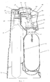
- Fig. 1 is a vertical view of an apparatus according to an embodiment of the invention, parts of it being in cross-section;
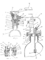
- Fig. 2 is a vertical cross-section at an enlarged scale of part of the apparatus of Fig. 1;
- Fig. 3 is a cross-section of a detail of Fig. 2, taken on the plane III-III of Fig. 2, looking in the direction of the arrows; and
- Fig. 4 (a), (b) and (c) is a schematic illustration, in vertical view with details shown at an enlarged scale, of how a pressure release valve, according to an embodiment of the invention, is actuated to release pressure or prevent formation thereof when the bottle, which is in the apparatus, is not in the correct position.
- With reference now to the drawings, an apparatus according to an embodiment of the invention comprises a main body generally indicated at 10. Mounted on said
body 10 is a bottle receiving means, viz. an aeratinghead assembly 11, hinged on the body at 12 so as to be capable of being swung outwards (in counter-clockwise direction, as seen in Fig. 1) for insertion of a bottle indicated at 13. Once a bottle is fitted on said head assembly and released, it will swing back under its own weight, rotating abouthinge 12, until it comes into contact with asurface 14, hereinafter called "reference surface". This occurs because the center of gravity of the bottle and aerating assembly together is offset outwardly with respect to thepivot 12. If the profile of the bottle is not as it should be, only parts thereof, particularly the parts that jut outwardly with respect to the ideal profile, will contact thesurface 14. Other, direct or indirect, means could be provided by skilled persons for comparing the profile of the bottle with that of the reference surface, which could be mounted in the apparatus in a different position and in a different way, and for detecting any discrepancies between them. - The
bottle 13, containing liquid to be aerated, is engaged with saidhead 11 and is held in engagement with the same by means of anexternal thread 15 provided on the bottle which engages aninternal thread 16 provided in thehead 11, or other suitable means, aflange 17 or like means being provided on the neck of the bottle for limiting the distance by which thebottle 13 screws into the aeratinghead assembly 11. When fully screwed in, the open top end of thebottle 13 contacts anelastic gasket 18, preferably made of rubber and provided with a rigidstiffening sleeve 19, or like means, with sufficient pressure to create a gas and fluid tight seal. Of course, if thebottle 13 is not correctly fitted against thegasket 18, a fluid or gas tight seal will not be effected, and the bottle will not become pressurized. - The aerating
head assembly 11 accommodates atube 20 which extends throughgasket 18, against which the mouth of the neck of thebottle 13 is engaged, and down inside thebottle 13. At its lower end the tube is threaded into ajet 21 which has asmall bore 22 matching with the bore of said tube at 23. - The aerating
head 11 comprises anupper part 24 and alower part 25, which is connected to the upper part in any suitable way, e.g. by means ofscrews 26. A suitable sealing means, in this case aring 27, which is part of thegasket 18, insures liquid and gas tight seal between the two parts of the aeratinghead 11. - The upper end of
tube 20 is threaded at 28 into theupper part 24 of the aeratinghead 11 and communicates at its upper end with a passage or bore 29, which is connected to aflexible tube 30 by aconnection 31, which ends in abore 32 of agas cylinder holder 33 and is held therein by aconnector 34.Bore 32 in turn communicates withchamber 36 ofcylinder holder 33. -
Cylinder holder 33 is threaded internally at 37 to receive an externally threadedboss 38 of avalve body 39 which is screwed at 40 onto theneck 41 of asmall gas cylinder 42. Thevalve body 39 is part of avalve assembly 45 which is fitted on eachgas cylinder 42, so that a used gas cylinder can be removed together with its valve assembly from thecylinder holder 33 and a fully charged cylinder with itsown valve assembly 45 can be fitted in its place. - The
valve body 39 has avalve chamber 44 which houses aspring 43. Thevalve assembly 45 further comprises avalve pin 46 bonded to agasket 47, which pin is urged byspring 43 against a seat formed at the lower end of aninsert 49, which is provided with a bore through which aprojection 50 ofpin 46 passes. - The
cylinder holder 33 is fitted with aplunger 51 which can be depressed by an external, manually operated, swingable, finger-actuatedlever 52, pivoted at 53 on said cylinder holder. Depression oflever 52 causes plunger 51 to slide downwards and press downwardsprojection 50 ofvalve pin 46, against the reaction ofspring 43, whereby to permit gas to pass fromcylinder 42 through the bore ofinsert 49 and intochamber 36 of the cylinder holder, therefrom throughflexible tube 30 and then intotube 20 which extends downward into thebottle 13 containing the liquid to be aerated. When thelever 52 is released, thespring 43 reasserts itself to urge thevalve pin 46 upwards against its seat and close thevalve 45, concurrently returning theplunger 51 upwards to its starting position. Thevalve body 39 may be provided with a subsidiary safety device, such as a blow outdisk 55 which acts to release excess pressure in thegas cylinder 42. - The finger actuated
lever 52 can be depressed when the aeratinghead 11 is in the vicinity of its fully swung downwards position, which is the aerating position. This is because the aeratinghead 11 is solid with aplate 56 which, as seen in Fig. 1, prohibits depression oflever 52 when it is swung away from the aerating position by an angle greater than a predetermined tolerance angle, as will be explained hereinafter, whereby to prevent undesirable or unsafe discharge of gas. - The aerating
head assembly 11 comprises anupper aerating head 24, fitted with a pressure releasevalve carrier assembly 57 and a safetyvalve carrier assembly 58, both fastened to theupper aerating head 24 byscrews 59 and more particularly seen in Fig. 3. Theinner chamber 70 of theupper aerating head 24 communicates with exhaustvalve carrier assembly 57 by means of a bore 60 and with safetyvalve carrier assembly 58 by means of abore 61. - The exhaust
valve carrier assembly 57 comprises an exhaustvalve carrier body 62, fitted with anexhaust valve 63, and aplunger 64 with aring 65, which seals at 66 against the exhaustvalve carrier body 62 when internal pressure is applied. In the absence of pressure,plunger 64 falls back due to gravity until its lower end rests lightly on apoppet 67 of the valve, which is forced against a seat by aspring 68. When pressure is applied to the system with the aerating head in its correct position,plunger 64 is urged upwards until a gas tight seal is made byring 65seating 66. When the pressure in the system has reached a predetermined threshoid value, e. g. 105 psi, and the aerating has been completed,spring 68 will yield and the gas will be vented to the atmosphere. - Further, independently of the degree of pressure in the bottle, when the aerating head is swung away from its correct position,
plunger 64 will be depressed bycam 69 and will pushring 65 off its seat, thereby allowing pressure to escape, as gas fromchamber 70 passes through the clearance between the plunger and the bore of thevalve body 62. How this occurs, is schematically illustrated in Fig. 4, the cam and the plunger being also shown therein as a detail at an enlarged scale. Fig. 4 (a) shows abottle 13 having the correct, standard profile, which bottle therefore is in its correct position, when loaded in the apparatus. In this case, theplunger 64 ofexhaust valve assembly 57 is close to azone 78 ofcam 69, which represents a recess in the cam profile, a slight gap remaining therebetween, so that the plunger is in its uppermost position,poppet 67 engages its seat and the exhaust valve is closed (of course, if the pressure is below its threshold value). If a bottle 13' has swollen under pressure or had from the start a diameter in excess of the correct value at any point of its contour, as in Fig. 4 (b), the bottle will be shifted (in a counterclockwise direction, looking at the drawings) from its correct position. The point of contact ofplunger 64 withcam 69 will have shifted, as shown in Fig. 4 (b), to the left looking at the drawing, and will now be onsurface 79 of the cam, which is slanted outwards with respect tozone 78, wherebyplunger 64 will have been depressed, displacingring 65 off its seating face at 66 to release pressure. The same depression of the plunger will occur if the bottle has a diameter which is below the correct, standard value, as shown in Fig. 4 (c). The point of contact ofplunger 64 withcam 69 will now be inportion 80 of the cam arc, to the right (looking at the drawing) ofzone 78 .Portion 80 is more sharply slanted outwards thanportion 79, so that a smaller angular displacement of the aerating head and a smaller linear displacement of the point of contact of the plunger with the cam will now suffice to actuate thering 65 from itsseating face 66 to release pressure.Plunger 75 ofsafety valve 72 will cooperate in a similar manner withcam 77. - The actuation of the exhaust valve in the situation of Fig. 4 (b) will occur when the
plunger 64 has travelled a few millimeters, preferably not more than 3 mm and still more preferably about 1.7 mm, alongportion 78 of the cam arc. In the embodiment described, the initial distance of thepivot 12 from the vertex ofzone 78 ofcam 69 is 87 mm, and a linear displacement of the plunger of 3 mm corresponds to a displacement angle of about 2°. This figure indicates the order of magnitude of the angular displacement which actuatesplunger 64 and therefore of the sensitivity of the safety device represented byring 65 and itsseating 66. Of course, the displacement angle may change depending on the dimensions of the device, and e. g. on the distance of the displacement pivot, such as 12, from the correct contact point of plunger and cam (which is the radius of the angular displacement), on the distance from said pivot to the zones of the bottle where an expansion may take place and on the extent to which such an expansion may be tolerated. The minimum linear displacement of the plunger, with respect to the pivot, that will displacering 65 off itsseat 66, as described, can also change depending on the various dimensions mentioned, but it can be easily determined by a skilled person in each particular instance, based on the typical values indicated herein. - The
punger 64 will be actuated in the same way, to displacering 65 from its seat, if a bottle the diameter of which is greater than the correct one at any point of its contour is loaded on the machine. The aerating head will be angularly displaced from its correct position, because of the excess diameter, exactly as if a bottle having the right size and shape had been loaded and had expanded as a result of pressurization, andplunger 64 will be displaced in the same manner alongcam 69 and be depressed thereby, thus displacingring 65 from its seat. The same values of linear and angular displacements, set forth hereinbefore for the case of an expanded bottle, will apply to this case. - On the other hand, if the bottle diameter is below it correct value, the situation which is created is that of Fig, 4 (c) and the minimum displacement which causes displacement of
ring 65 from its seat to release pressure will be in the same order of magnitude, but preferably smaller, e. g. by about one third, than that which causes such actuation in the case of Fig. 4 (b). E. g. its minimum value should preferably be not greater than 2 mm and still more preferably should be about 1 mm. - Considering now the aerating of a bottle of correct dimensions, pressure is released once the aerating has been completed and the pressure threshold has been reached, and then the bottle is swung with the aerating head in the direction required to unload the bottle - counterclockwise, as seen in the drawings. This swinging of the aerating head continues beyond the angle which actuates
valve 63, and at that time, and before a position is reached in which it is possible to remove the bottle from the apparatus, theplunger 64 will be pushed down bycam 69 and will displacepoppet 67 from its seat. This will not normally vent any pressure, as pressure should normally have been released already, but provides an additional safety in case of any malfunction that might have caused any pressure to remain in the system. Further, in the case that the poppet had become stuck to its seat, due to the machine's not having been used for some time or for any other cause, it will be freed when theplunger 64 is depressed by thecam 69 as the aerating head is swung forward for the purpose of inserting a bottle, and this will guarantee that the valve operates properly when the system is pressurized. - The
safety valve assembly 58 comprises safetyvalve carrier body 71 fitted with a safety,pressure release valve 72 which comprises avalve ball 73 and aspring 74 urging theball 73 against its seat. In the body 71 aplunger 75, provided with arubber ring 76, is slidably mounted. When a predetermined threshold pressure, marginally higher than the threshold pressure of the exhuast valve, e. g. 130 psi, has been reached because the exhaust valve has not released it for any reason,spring 74 will yield,valve ball 73 will be displaced from its seat, and pressure be released from the bottle throughchamber 70 and bore 61 to the atmosphere. Thesafety valve 72 will also be actuated whenever the aerating head assembly is swung forwards (counterclockwise in the drawings) in a manner similar to that of the exhaust valve, as already noted, becauseplunger 75 will bear againstcam 77 and be depressed by it, thus displacingball 73 off its seat. However the profile ofcam 77 and its relationship to plunger 75 are such that the displacement angle required so to actuate thesafety valve 72 is larger than that required to actuateexhaust valve 63, though smaller than that required to unload the bottle from the apparatus. The aforesaid action ofplunger 75 onball 73 will also occur when the aerating head is swung forwards for inserting a bottle and will thus guarantee proper functioning of the valve during the aerating procedure and thereafter, even if theball 73 should have become stuck to its seat because of lack of use of the machine or for any other reason. - The
reference surface 14 is so formed that when a bottle having the correct shape and size and correctly screwed onto the aeratinghead 11 rests against it,cams plungers lever 52 will cause gas to pass from thecylinder 42 to the bottle, until the predetermined maximum pressure has been reached. - It is appreciated that it is the engagement of the bottle surface with the
reference surface 14 which determines the position of the bottle axis, and since this is necessarily aligned with the axis of the aerating head, determines the position of the aerating head. The "correct positions" of both are those which they assume when a bottle having the correct shape and size has come into contact withreference surface 14. However, there is a certain tolerance in the bottle's shapes and sizes, and therefore minor departures from the theoretical position, corresponding to an ideal perfect bottle, are tolerated, so that the expression "correct position" should be understood as including all positions differing from the ideal one by a tolerated amount. The tolerated amount is expressed by an angular tolerance, viz. by the angle by which the bottle and the aerating head must be displaced from the ideal position to cause thecams - Obviously, when the liquid in the bottle has been completely aerated and the bottle is swung upwards in order to remove it from the apparatus, the swinging motion will bring
plungers cams plate 56 reaches a position in which it preventslever 52 from being depressed and thus prohibits release of gas into the apparatus. However the angle by which the aerating head must be swung away from its correct position forplate 56 completely to prevent depression oflever 52, is substantially larger than the angle by which it must be swung forcam 69 to actuateplunger 64, e.g. it should be no less than 5°. Therefore the plungers and their valves can be actuated, as a result e.g. of a swelling of the bottle, even thoughlever 52 is still being depressed to effect pressurization. This is important, because the person operating the apparatus will generally not be aware that the bottle is swelling during the aerating process and will keep depressing thelever 52, and if this latter should engageplate 56 at too small an angle from the correct position of the aerating head, the mechanical functions which produce release of the pressure, as hereinbefore described, would be impeded.
Claims (16)
- Apparatus for aerating liquids contained in bottles, comprising a reference surface (14) for detecting any irregularity in the shape and/or dimensions of the bottle, means (12) for causing a bottle loaded on the apparatus to come into matching relationship with the reference surface, and means (69, 64) for preventing the build-up of pressure or releasing the pressure in the bottle, if the position of the bottle, when in such a relationship with the reference surface, does not correspond or ceases to correspond to the position of a bottle having the correct shape and dimensions.
- Apparatus according to claim 1, wherein said matching relationship is achieved through direct contact of the bottle with the reference surface.
- Apparatus according to claim 1, comprising means for causing the bottle to come into contact with the reference surface, which comprise means (11) for receiving the bottle in removable engagement, said bottle receiving means comprising means (12) for allowing the engaged bottle to become displaced towards the reference surface and abut against the same by gravity.
- Apparatus according to claim 3, wherein the means for allowing the engaged bottle to become displaced towards the reference surface and abut against the same by gravity comprise a pivot coupling (12) between said bottle receiving means (11) and support means rigid with the body (10) of the apparatus, said receiving means (11) being so structured that the cumulative centre of gravity of the bottle and the bottle receiving means, when they are mutually engaged, is offset with respect to the centre of said pivot coupling (12), whereby to cause the weight of the bottle to urge the same towards the reference surface (14).
- Apparatus according to claim 1, comprising at least a valve (65, 66) for placing the bottle and the parts of the apparatus which communicate therewith in the pressurizing operation in communication with the atmosphere, when open, and means (69, 64) for causing said valve to be open when the axis of the bottle is not in the correct position.
- Apparatus according to claim 5, wherein the means for causing said valve to open comprise a plunger (64) for displacing the valve closure element (65) from its seat and cam means (69) fixedly carried by the apparatus body and so shaped as to actuate said plunger when the bottle axis, and consequently the receiving means, are angularly displaced from the respective correct positions.
- Apparatus according to claim 6, wherein the minimum displacement angle that will cause the cam (69) to actuate the plunger (64) is in the order of a few degrees and the corresponding displacement of the point of contact of the plunger with the cam is in the order of a few millimeters.
- Apparatus according to claim 7, wherein said minimum displacement angle and said corresponding displacement of the point of contact of the plunger with the cam are smaller in the direction corresponding to bottle diameter smaller than standard than in the opposite direction.
- Apparatus according to claim 1, comprising two valves (63) and (72), one of which operates as an exhaust valve to release pressure, even if the bottle is in its correct position, when the pressure has reached a threshold value and the aerating has been completed, while the other operates in like manner at a higher threshold value, to provide additional safety in case of malfunction of the first.
- Apparatus according to claim 9, wherein at least one of said valves and preferably both valves are also cam-actuated to release pressure when the bottle is displaced from the correct position even if threshold pressure values have not been reached.
- Apparatus according to claim 10, wherein the cams (69, 77) and other parts of the apparatus are so structured that the said valve or valves will operate to discharge pressure and/or to prevent pressure from being built up when the bottle axis and the receiving means are displaced from the respective correct positions in either direction, whereby bottles that are too thin or have excessively thin contour portions will also not be pressurized.
- Apparatus according to claim 5, comprising, in combination with hand-operatable means (52) for placing a gas cylinder, loaded onto it, in communication with the inside of a bottle also loaded onto it, means (56) for preventing said hand-operatable means from being actuated if the bottle axis and the bottle receiving means are displaced from the correct position by an amount insufficient to permit unloading the bottle from the apparatus but greater than the amount required to actuate the pressure releasing valves to release pressure.
- Apparatus according to claim 1, comprising a body (10), an aerating head (11) having means for attaching thereto in gas tight sealing relationship a bottle containing liquid to be aerated and pivoted to said body about a point (12) vertically offset from the cumulative centre of gravity of said head and a filled bottle attached thereto, a reference surface (14) attached to said body and so positioned that a bottle attached to said head will swing into contact with it by action of gravity, means (33, 37) in said body for receiving a gas cylinder provided with aerating valve means (45), means (51, 52) for actuating said aerating valve means, conduit means (20, 30) connecting said aerating valve means through said aerating head with the inside of the bottle, whereby to aerate the liquid contained therein when the aerating valve means are operated, gas venting means (63) operative to discharge pressure from the bottle and the comunicating parts of the apparatus when the aeration has been completed, and valve means (65, 66) operative so to discharge pressure and to prevent formation of pressure when the bottle attached to the aerating head is not in a predetermined correct position corresponding to a correct shape and dimensions of the bottle.
- Apparatus according to claim 13, comprising cam means (69, 77) defined on the apparatus body and engaging plungers (64, 75) operative to cause opening of at least a valve means to release or preventing formation of pressure when the bottle attached to the aerating head is not in the correct position.
- Apparatus according to claim 13, comprising means (56) for preventing the actuation of the aerating valve applied to the cylinder when the bottle attached to the aerating head is not in the correct position.
- Apparatus according to claim 15, wherein said actuation preventing means do not cause interference of aerating valve actuating means with the operation of the safety valve.
Applications Claiming Priority (2)
| Application Number | Priority Date | Filing Date | Title |
|---|---|---|---|
| IL9541390A IL95413A (en) | 1990-08-17 | 1990-08-17 | Liquid aerating apparatus |
| IL95413 | 1990-08-17 |
Publications (2)
| Publication Number | Publication Date |
|---|---|
| EP0472995A1 EP0472995A1 (en) | 1992-03-04 |
| EP0472995B1 true EP0472995B1 (en) | 1994-07-13 |
Family
ID=11061519
Family Applications (1)
| Application Number | Title | Priority Date | Filing Date |
|---|---|---|---|
| EP91113544A Expired - Lifetime EP0472995B1 (en) | 1990-08-17 | 1991-08-13 | Liquid aerating apparatus |
Country Status (26)
| Country | Link |
|---|---|
| US (1) | US5209378A (en) |
| EP (1) | EP0472995B1 (en) |
| JP (1) | JP2803767B2 (en) |
| KR (1) | KR100220116B1 (en) |
| AR (1) | AR247367A1 (en) |
| AT (1) | ATE108417T1 (en) |
| AU (1) | AU639130B2 (en) |
| BR (1) | BR9103534A (en) |
| CA (1) | CA2049363C (en) |
| CZ (1) | CZ283120B6 (en) |
| DE (1) | DE69102842T2 (en) |
| DK (1) | DK0472995T3 (en) |
| ES (1) | ES2056534T3 (en) |
| HU (1) | HU215101B (en) |
| IL (1) | IL95413A (en) |
| LT (1) | LT3739B (en) |
| LV (1) | LV11053B (en) |
| MX (1) | MX9100694A (en) |
| NO (1) | NO302464B1 (en) |
| NZ (1) | NZ239439A (en) |
| PL (1) | PL167522B1 (en) |
| RU (1) | RU2040708C1 (en) |
| SK (1) | SK280712B6 (en) |
| TW (1) | TW208690B (en) |
| UA (1) | UA26129A (en) |
| ZA (1) | ZA916513B (en) |
Cited By (7)
| Publication number | Priority date | Publication date | Assignee | Title |
|---|---|---|---|---|
| EP0894769A2 (en) * | 1997-08-01 | 1999-02-03 | Eduard Wintner | Apparatus for releasing carbon dioxide into drinking water |
| DE19746044C1 (en) * | 1997-10-17 | 1999-07-22 | Benno Fell Fa | Device for introducing gases into liquids |
| TR199900281A2 (en) | 1999-01-11 | 2000-08-21 | Peter Kautz | Device for adding gas to liquids. |
| WO2001041907A2 (en) * | 1999-12-11 | 2001-06-14 | Soda-Club (Co¿2?) Sa | Carbonating device |
| US6319414B1 (en) * | 1997-10-05 | 2001-11-20 | Soda Club (Co2) Atlantic Gmbh | Water purifying and dispensing apparatus |
| AU762280B2 (en) * | 1998-09-17 | 2003-06-19 | Soda-Club (Co2) Sa | Safety device for liquid aerating apparatus |
| US6789698B2 (en) | 2002-01-23 | 2004-09-14 | Kwc Ag | Device by means of which a supply container is connected in a sealed manner to a consumer element, and consumer element |
Families Citing this family (20)
| Publication number | Priority date | Publication date | Assignee | Title |
|---|---|---|---|---|
| FR2700159B1 (en) * | 1993-01-05 | 1995-02-10 | Air Liquide | Unit unit of beverage keg and gas tank. |
| EP0935992A1 (en) | 1998-02-10 | 1999-08-18 | Kautz, Peter | Apparatus for enriching a liquid with gas |
| TR199801497U (en) | 1998-08-03 | 2000-03-21 | Çağlar Şeref | Innovation in soda machines. |
| KR100689643B1 (en) | 2004-12-31 | 2007-03-09 | (주)포사이버 | The drinks-maker |
| US10631558B2 (en) | 2006-03-06 | 2020-04-28 | The Coca-Cola Company | Methods and apparatuses for making compositions comprising an acid and an acid degradable component and/or compositions comprising a plurality of selectable components |
| EP1905504A1 (en) * | 2006-09-26 | 2008-04-02 | Kuei-Tang Chang | Gas feeding device for soda machine |
| RU2333781C1 (en) * | 2007-03-13 | 2008-09-20 | Общество С Ограниченной Ответственностью "Евростандарт" | Device for treatment and purification of liquid product |
| US8162176B2 (en) | 2007-09-06 | 2012-04-24 | The Coca-Cola Company | Method and apparatuses for providing a selectable beverage |
| CN201995545U (en) * | 2011-03-15 | 2011-10-05 | 宋宁 | Aerated water machine with pressure regulator |
| CN201995544U (en) * | 2011-03-15 | 2011-10-05 | 宋宁 | Aerated water machine with safety device |
| RS57826B1 (en) * | 2011-08-10 | 2018-12-31 | Sodastream Ind Ltd | Soda machine pronged clamp |
| USD679933S1 (en) | 2011-11-22 | 2013-04-16 | Primo Products, LLC | Beverage maker |
| WO2015198233A1 (en) * | 2014-06-24 | 2015-12-30 | Sodastream Industries Ltd. | Automatic release of pressure in a home soda machine |
| CN204394246U (en) * | 2015-01-12 | 2015-06-17 | 宋宁 | A kind of split type beverage machine |
| CN108799512A (en) * | 2018-08-30 | 2018-11-13 | 深圳市长治电子科技有限公司 | A kind of high pressure valve |
| KR20200053097A (en) | 2018-11-08 | 2020-05-18 | 유민규 | Carbonated beverage maker using tea bag type container |
| CN210520794U (en) * | 2019-04-01 | 2020-05-15 | 关进业 | Submachine with fast and slow exhaust function |
| CN110529604B (en) * | 2019-10-23 | 2020-12-01 | 时新(上海)产品设计有限公司 | Gas control valve and control method thereof, and beverage aerating device |
| JP2023516768A (en) * | 2020-03-05 | 2023-04-20 | ソーダキング アイピーブイ ピーティーワイ リミテッド | On-demand beverage carbonator |
| CA3225685A1 (en) * | 2021-07-15 | 2023-01-19 | Stefan Stalder | Receiving device for receiving a gas cartridge for a carbonation machine; carbonation machine; method for using a carbonation machine |
Family Cites Families (9)
| Publication number | Priority date | Publication date | Assignee | Title |
|---|---|---|---|---|
| GB1055000A (en) * | 1963-10-26 | 1900-01-01 | ||
| US3685694A (en) * | 1969-12-18 | 1972-08-22 | Yan Nell Corp | Liquid dispenser plastic bottle and receptacle with piercing units |
| US3658694A (en) | 1969-12-22 | 1972-04-25 | Phillips Petroleum Co | Method for treating fluid hydrocarbons containing sulfur and other impurities in a solid reagent hydrocarbon treater and separator |
| GB1453363A (en) * | 1974-04-24 | 1976-10-20 | Sodastream Ltd | Apparatus for aerating liquids |
| US4082123A (en) * | 1976-10-26 | 1978-04-04 | Sodaflo Drinks Limited | Carbonating apparatus |
| EP0037670B1 (en) * | 1980-04-02 | 1983-06-29 | THORN EMI Domestic Appliances Limited | Aerated drinks machine |
| US4407432A (en) * | 1980-12-22 | 1983-10-04 | United States Surgical Corporation | Pressure relief system for pressurized gas containers |
| GB2093714A (en) * | 1981-02-24 | 1982-09-08 | Thorn Cascade Co Ltd | Carbonated drinks machine |
| IL71353A (en) * | 1983-04-08 | 1987-10-20 | Sodastream Ltd | Liquid carbonating apparatus |
-
1990
- 1990-08-17 IL IL9541390A patent/IL95413A/en unknown
-
1991
- 1991-08-13 DE DE69102842T patent/DE69102842T2/en not_active Expired - Lifetime
- 1991-08-13 EP EP91113544A patent/EP0472995B1/en not_active Expired - Lifetime
- 1991-08-13 DK DK91113544.0T patent/DK0472995T3/en active
- 1991-08-13 AT AT91113544T patent/ATE108417T1/en not_active IP Right Cessation
- 1991-08-13 ES ES91113544T patent/ES2056534T3/en not_active Expired - Lifetime
- 1991-08-15 NO NO913192A patent/NO302464B1/en unknown
- 1991-08-15 US US07/746,113 patent/US5209378A/en not_active Expired - Lifetime
- 1991-08-16 JP JP3206052A patent/JP2803767B2/en not_active Expired - Fee Related
- 1991-08-16 AR AR91320424A patent/AR247367A1/en active
- 1991-08-16 CA CA002049363A patent/CA2049363C/en not_active Expired - Fee Related
- 1991-08-16 MX MX9100694A patent/MX9100694A/en not_active IP Right Cessation
- 1991-08-16 RU SU915001445A patent/RU2040708C1/en active
- 1991-08-16 CZ CS912555A patent/CZ283120B6/en not_active IP Right Cessation
- 1991-08-16 AU AU82541/91A patent/AU639130B2/en not_active Ceased
- 1991-08-16 NZ NZ239439A patent/NZ239439A/en not_active IP Right Cessation
- 1991-08-16 ZA ZA916513A patent/ZA916513B/en unknown
- 1991-08-16 HU HU912735A patent/HU215101B/en not_active IP Right Cessation
- 1991-08-16 UA UA5001445A patent/UA26129A/en unknown
- 1991-08-16 PL PL91291447A patent/PL167522B1/en unknown
- 1991-08-16 SK SK2555-91A patent/SK280712B6/en unknown
- 1991-08-16 BR BR919103534A patent/BR9103534A/en not_active IP Right Cessation
- 1991-08-17 KR KR1019910014207A patent/KR100220116B1/en not_active IP Right Cessation
- 1991-08-22 TW TW080106663A patent/TW208690B/zh active
-
1993
- 1993-06-29 LV LVP-93-749A patent/LV11053B/en unknown
-
1994
- 1994-01-27 LT LTIP1805A patent/LT3739B/en not_active IP Right Cessation
Cited By (8)
| Publication number | Priority date | Publication date | Assignee | Title |
|---|---|---|---|---|
| EP0894769A2 (en) * | 1997-08-01 | 1999-02-03 | Eduard Wintner | Apparatus for releasing carbon dioxide into drinking water |
| US6319414B1 (en) * | 1997-10-05 | 2001-11-20 | Soda Club (Co2) Atlantic Gmbh | Water purifying and dispensing apparatus |
| DE19746044C1 (en) * | 1997-10-17 | 1999-07-22 | Benno Fell Fa | Device for introducing gases into liquids |
| AU762280B2 (en) * | 1998-09-17 | 2003-06-19 | Soda-Club (Co2) Sa | Safety device for liquid aerating apparatus |
| US6648028B2 (en) * | 1998-09-17 | 2003-11-18 | Soda-Club (Co2) Atlantic Gmbh | Safety device for liquid aerating apparatus |
| TR199900281A2 (en) | 1999-01-11 | 2000-08-21 | Peter Kautz | Device for adding gas to liquids. |
| WO2001041907A2 (en) * | 1999-12-11 | 2001-06-14 | Soda-Club (Co¿2?) Sa | Carbonating device |
| US6789698B2 (en) | 2002-01-23 | 2004-09-14 | Kwc Ag | Device by means of which a supply container is connected in a sealed manner to a consumer element, and consumer element |
Also Published As
Similar Documents
| Publication | Publication Date | Title |
|---|---|---|
| EP0472995B1 (en) | Liquid aerating apparatus | |
| US4298551A (en) | Appliance for making an aerated beverage | |
| US4265374A (en) | Pressure liquid dispenser | |
| EP1113977B1 (en) | Safety device for liquid aerating apparatus | |
| EP0248083A1 (en) | Filling valve for counterpressure filling of cans | |
| JPS6230809B2 (en) | ||
| CA1302213C (en) | Tire inflating device, particularly for inflating bicycle tires | |
| US20100140265A1 (en) | Container having co2 compressed gas source and overpressure burst safeguard | |
| JP2001139095A (en) | Gas flush filling machine | |
| EP3877321A2 (en) | Bag-in-keg container with valve sealing lip | |
| JP2023516553A (en) | Beverage container stopper and pressure system | |
| GB2190007A (en) | Liquid aerating apparatus with safety valve | |
| RU205886U1 (en) | Pressure relief cap | |
| JPS6036330Y2 (en) | carbonated beverage manufacturing equipment | |
| JPH0738228Y2 (en) | Liquid filling container base | |
| JPH082147Y2 (en) | Tip stop type adapter for pressurized fluid ejector | |
| IL141662A (en) | Safety device for liquid aerating apparatus | |
| AU2120088A (en) | Improved beverage dispenser | |
| CZ279770B6 (en) | Filling valve of an excessive-pressure bottle-filling machine |
Legal Events
| Date | Code | Title | Description |
|---|---|---|---|
| PUAI | Public reference made under article 153(3) epc to a published international application that has entered the european phase |
Free format text: ORIGINAL CODE: 0009012 |
|
| AK | Designated contracting states |
Kind code of ref document: A1 Designated state(s): AT BE CH DE DK ES FR GB GR IT LI LU NL SE |
|
| 17P | Request for examination filed |
Effective date: 19920713 |
|
| 17Q | First examination report despatched |
Effective date: 19930127 |
|
| GRAA | (expected) grant |
Free format text: ORIGINAL CODE: 0009210 |
|
| AK | Designated contracting states |
Kind code of ref document: B1 Designated state(s): AT BE CH DE DK ES FR GB GR IT LI LU NL SE |
|
| REF | Corresponds to: |
Ref document number: 108417 Country of ref document: AT Date of ref document: 19940715 Kind code of ref document: T |
|
| REF | Corresponds to: |
Ref document number: 69102842 Country of ref document: DE Date of ref document: 19940818 |
|
| REG | Reference to a national code |
Ref country code: DK Ref legal event code: T3 |
|
| REG | Reference to a national code |
Ref country code: ES Ref legal event code: FG2A Ref document number: 2056534 Country of ref document: ES Kind code of ref document: T3 |
|
| ITF | It: translation for a ep patent filed |
Owner name: SAIC BREVETTI S.R.L. |
|
| ET | Fr: translation filed | ||
| REG | Reference to a national code |
Ref country code: GR Ref legal event code: FG4A Free format text: 3013443 |
|
| EAL | Se: european patent in force in sweden |
Ref document number: 91113544.0 |
|
| PLBE | No opposition filed within time limit |
Free format text: ORIGINAL CODE: 0009261 |
|
| STAA | Information on the status of an ep patent application or granted ep patent |
Free format text: STATUS: NO OPPOSITION FILED WITHIN TIME LIMIT |
|
| 26N | No opposition filed | ||
| REG | Reference to a national code |
Ref country code: GB Ref legal event code: 732E |
|
| REG | Reference to a national code |
Ref country code: GB Ref legal event code: IF02 |
|
| REG | Reference to a national code |
Ref country code: CH Ref legal event code: NV Representative=s name: HEPP, WENGER & RYFFEL AG Ref country code: CH Ref legal event code: PFA Owner name: SODA CLUB HOLDINGS N.V. Free format text: SODA CLUB HOLDINGS N.V.#DE RUYTERKADE 62 P.O. BOX 812#CURACAO (AN) -TRANSFER TO- SODA CLUB HOLDINGS N.V.#DE RUYTERKADE 62 P.O. BOX 812#CURACAO (AN) |
|
| PGFP | Annual fee paid to national office [announced via postgrant information from national office to epo] |
Ref country code: LU Payment date: 20050921 Year of fee payment: 15 |
|
| PGFP | Annual fee paid to national office [announced via postgrant information from national office to epo] |
Ref country code: ES Payment date: 20050927 Year of fee payment: 15 |
|
| PGFP | Annual fee paid to national office [announced via postgrant information from national office to epo] |
Ref country code: NL Payment date: 20060803 Year of fee payment: 16 |
|
| PGFP | Annual fee paid to national office [announced via postgrant information from national office to epo] |
Ref country code: AT Payment date: 20060811 Year of fee payment: 16 |
|
| PGFP | Annual fee paid to national office [announced via postgrant information from national office to epo] |
Ref country code: DK Payment date: 20060815 Year of fee payment: 16 |
|
| PGFP | Annual fee paid to national office [announced via postgrant information from national office to epo] |
Ref country code: IT Payment date: 20060831 Year of fee payment: 16 |
|
| PGFP | Annual fee paid to national office [announced via postgrant information from national office to epo] |
Ref country code: BE Payment date: 20061013 Year of fee payment: 16 |
|
| REG | Reference to a national code |
Ref country code: ES Ref legal event code: FD2A Effective date: 20060814 |
|
| PG25 | Lapsed in a contracting state [announced via postgrant information from national office to epo] |
Ref country code: ES Free format text: LAPSE BECAUSE OF NON-PAYMENT OF DUE FEES Effective date: 20060814 |
|
| BERE | Be: lapsed |
Owner name: *SODA CLUB HOLDINGS N.V. Effective date: 20070831 |
|
| REG | Reference to a national code |
Ref country code: DK Ref legal event code: EBP |
|
| PG25 | Lapsed in a contracting state [announced via postgrant information from national office to epo] |
Ref country code: NL Free format text: LAPSE BECAUSE OF NON-PAYMENT OF DUE FEES Effective date: 20080301 |
|
| NLV4 | Nl: lapsed or anulled due to non-payment of the annual fee |
Effective date: 20080301 |
|
| PGFP | Annual fee paid to national office [announced via postgrant information from national office to epo] |
Ref country code: GR Payment date: 20070813 Year of fee payment: 17 |
|
| PG25 | Lapsed in a contracting state [announced via postgrant information from national office to epo] |
Ref country code: AT Free format text: LAPSE BECAUSE OF NON-PAYMENT OF DUE FEES Effective date: 20070813 |
|
| PG25 | Lapsed in a contracting state [announced via postgrant information from national office to epo] |
Ref country code: DK Free format text: LAPSE BECAUSE OF NON-PAYMENT OF DUE FEES Effective date: 20070831 Ref country code: LU Free format text: LAPSE BECAUSE OF NON-PAYMENT OF DUE FEES Effective date: 20060813 |
|
| PG25 | Lapsed in a contracting state [announced via postgrant information from national office to epo] |
Ref country code: BE Free format text: LAPSE BECAUSE OF NON-PAYMENT OF DUE FEES Effective date: 20070831 |
|
| REG | Reference to a national code |
Ref country code: CH Ref legal event code: PFA Owner name: SODA-CLUB ENTERPRISES N.V. Free format text: SODA CLUB HOLDINGS N.V.#DE RUYTERKADE 62 P.O. BOX 812#CURACAO (AN) -TRANSFER TO- SODA-CLUB ENTERPRISES N.V.#DE RUYTERKADE 62 P.O. BOX 812#CURACAO (AN) |
|
| PG25 | Lapsed in a contracting state [announced via postgrant information from national office to epo] |
Ref country code: GR Free format text: LAPSE BECAUSE OF NON-PAYMENT OF DUE FEES Effective date: 20090304 |
|
| PG25 | Lapsed in a contracting state [announced via postgrant information from national office to epo] |
Ref country code: IT Free format text: LAPSE BECAUSE OF NON-PAYMENT OF DUE FEES Effective date: 20070813 |
|
| PGFP | Annual fee paid to national office [announced via postgrant information from national office to epo] |
Ref country code: SE Payment date: 20100812 Year of fee payment: 20 Ref country code: FR Payment date: 20100901 Year of fee payment: 20 Ref country code: DE Payment date: 20100812 Year of fee payment: 20 |
|
| PGFP | Annual fee paid to national office [announced via postgrant information from national office to epo] |
Ref country code: GB Payment date: 20100811 Year of fee payment: 20 |
|
| PGFP | Annual fee paid to national office [announced via postgrant information from national office to epo] |
Ref country code: CH Payment date: 20101026 Year of fee payment: 20 |
|
| REG | Reference to a national code |
Ref country code: DE Ref legal event code: R071 Ref document number: 69102842 Country of ref document: DE |
|
| REG | Reference to a national code |
Ref country code: DE Ref legal event code: R071 Ref document number: 69102842 Country of ref document: DE |
|
| REG | Reference to a national code |
Ref country code: CH Ref legal event code: PL |
|
| REG | Reference to a national code |
Ref country code: GB Ref legal event code: PE20 Expiry date: 20110812 |
|
| REG | Reference to a national code |
Ref country code: SE Ref legal event code: EUG |
|
| PG25 | Lapsed in a contracting state [announced via postgrant information from national office to epo] |
Ref country code: GB Free format text: LAPSE BECAUSE OF EXPIRATION OF PROTECTION Effective date: 20110812 |
|
| PG25 | Lapsed in a contracting state [announced via postgrant information from national office to epo] |
Ref country code: DE Free format text: LAPSE BECAUSE OF EXPIRATION OF PROTECTION Effective date: 20110814 |