EP0472928A1 - Circuit arrangement to reduce harmonic currents - Google Patents
Circuit arrangement to reduce harmonic currents Download PDFInfo
- Publication number
- EP0472928A1 EP0472928A1 EP91112660A EP91112660A EP0472928A1 EP 0472928 A1 EP0472928 A1 EP 0472928A1 EP 91112660 A EP91112660 A EP 91112660A EP 91112660 A EP91112660 A EP 91112660A EP 0472928 A1 EP0472928 A1 EP 0472928A1
- Authority
- EP
- European Patent Office
- Prior art keywords
- phase
- ils
- ills
- circuit arrangement
- harmonic currents
- Prior art date
- Legal status (The legal status is an assumption and is not a legal conclusion. Google has not performed a legal analysis and makes no representation as to the accuracy of the status listed.)
- Ceased
Links
Images
Classifications
-
- H—ELECTRICITY
- H02—GENERATION; CONVERSION OR DISTRIBUTION OF ELECTRIC POWER
- H02M—APPARATUS FOR CONVERSION BETWEEN AC AND AC, BETWEEN AC AND DC, OR BETWEEN DC AND DC, AND FOR USE WITH MAINS OR SIMILAR POWER SUPPLY SYSTEMS; CONVERSION OF DC OR AC INPUT POWER INTO SURGE OUTPUT POWER; CONTROL OR REGULATION THEREOF
- H02M1/00—Details of apparatus for conversion
- H02M1/12—Arrangements for reducing harmonics from ac input or output
-
- H—ELECTRICITY
- H02—GENERATION; CONVERSION OR DISTRIBUTION OF ELECTRIC POWER
- H02M—APPARATUS FOR CONVERSION BETWEEN AC AND AC, BETWEEN AC AND DC, OR BETWEEN DC AND DC, AND FOR USE WITH MAINS OR SIMILAR POWER SUPPLY SYSTEMS; CONVERSION OF DC OR AC INPUT POWER INTO SURGE OUTPUT POWER; CONTROL OR REGULATION THEREOF
- H02M7/00—Conversion of ac power input into dc power output; Conversion of dc power input into ac power output
- H02M7/02—Conversion of ac power input into dc power output without possibility of reversal
- H02M7/04—Conversion of ac power input into dc power output without possibility of reversal by static converters
- H02M7/06—Conversion of ac power input into dc power output without possibility of reversal by static converters using discharge tubes without control electrode or semiconductor devices without control electrode
- H02M7/08—Conversion of ac power input into dc power output without possibility of reversal by static converters using discharge tubes without control electrode or semiconductor devices without control electrode arranged for operation in parallel
Definitions
- the present invention relates to a method and a circuit arrangement according to the preamble of patent claims 1 and 4, respectively.
- Rectifier units used in power supply systems typically generate harmonic currents that are returned to the supply network.
- the maximum permissible values for these harmonic currents are specified in the national and international regulations and must not be exceeded by the consumer.
- Information about harmonic currents and their limit values for the Swiss power supply network are e.g. in the Swiss standard 413600 or EN 60555 (SEV 3600 or SEV 8601).
- harmonic currents are usually reduced in practice by means of harmonic filters, reactive current capacitors and series chokes.
- this reduction in harmonic currents is often insufficient, so that the consumer is additionally forced to reduce the power consumption from the power supply network.
- the filter elements mentioned are very expensive.
- the present invention is therefore based on the object of specifying a method and a circuit arrangement which allows a partial or complete reduction of the disturbing harmonic currents.
- the circuit arrangement should also be realizable with little effort.
- the method according to the invention has the following advantages: Several harmonic currents of any atomic number can be almost completely reduced.
- the circuit arrangements for carrying out the method can be implemented with little effort, in particular when reducing harmonic currents which are only less critical.
- the basis for the method for reducing a harmonic current with the atomic number n is provided by the fact that when the fundamental wave is shifted in phase by the angle a, the nth harmonic is shifted by the n-fold angle (n x a).
- harmonic currents can be eliminated.
- phase shifts by 30 ° can be implemented relatively easily using a star-delta transformation.
- the variables A, B stand for the amplitudes of the currents i R and i Ip , i ll p; the variable w corresponds to the angular frequency of the fundamental wave.
- the phase shift a between the voltages delivered to the rectifier units GE1 and GE2 is chosen in such a way that the partial currents i R , i Ip , i IIp cancel each other out.
- the harmonic currents with the atomic number n then cancel each other out or complement each other to form an alternating current, the main component of which has the frequency of the fundamental wave. This also improves the power factor with which electrical power is delivered to the consumer.
- the power consumption via the rectifier units GE1, GE2 must of course be selected in such a way that the disturbing harmonic currents at the input of the rectifier units GE1 and GE2 have the same amplitude and the same shape. This ensures the complete reduction of these harmonic currents.
- the correct phase shift a can of course also be determined by professional measurement in the laboratory. That is, by continuously increasing the value for the phase shift a, it is determined at which values for a which harmonic currents are extinguished. With smaller values for a, harmonic currents with a higher atomic number are eliminated.
- possibilities for delivering phase-shifted voltages to rectifier units also result from transformers with a different connection of primary and secondary windings.
- a transformer whose primary windings are connected in star or delta can have three secondary windings connected in star and three in delta on the secondary side.
- the use of two or more transformers with a delta or star connection on the secondary side is functionally equivalent.
- phase-shifted voltages are in turn output to at least two rectifier units GE via the star or delta connections on the secondary side.
- a star-delta transformer for phase shifting, however, it is disadvantageous that the full apparent power must be transmitted via the three-phase transformer DT1, which necessitates a corresponding dimensioning of the three-phase transformer DT1.
- the value of the phase shift a cannot be changed arbitrarily.
- the supply lines R, S, T are connected on the one hand to the primary lp, illp, ilp connected in a delta connection and the center taps of the secondary windings ills, ils, is of a three-phase transformer DT2.
- the supply line R is connected to the primary and secondary windings Ip and Ills.
- the specified wiring of the three-phase transformer DT2 results in voltages ux, vy, wz in the secondary windings Ills, Ils, Is, the vectors of which are perpendicular to the vectors of the voltages which, via the supply lines R, S, T, the corresponding center taps of the secondary windings Ills, Ils, Is fed.
- the upper and lower connections of the secondary windings Is, Ils, Ills are also connected to rectifier units GE3 and GE4.
- the vectors of the voltages uvw, xyz output from the three-phase transformer DT2 to the rectifier units GE3 and GE4 are recorded in FIG. 3. It can easily be seen that the vector of the voltage of the supply line R is perpendicular to the vector of the voltage on the secondary winding Ills and is connected to it in the middle.
- the vectors of the voltages of the primary and secondary windings lp, Is; Ilp, Ils; Illp, Ills are parallel to each other.
- rectifier units GE3 and GE4 can be connected to the three-phase transformer DT2.
- three rectifier units GE can be provided, which are controlled with phase shifts of 0 and +/- a / 2 relative to the supply voltages.
- rectifier units GE can also be connected to further taps preferably provided symmetrically on the secondary windings (IS, ILS, ILS).
- the use of a three-phase transformer as shown in FIG. 3 also has the advantage that only a fraction of the apparent power has to be transmitted via the three-phase transformer DT2, the Apparent power is smaller on the primary side than on the secondary side.
- the three-phase transformer DT2 in the present case is mainly designed to generate the desired phase shift a.
- a plurality of three-phase transformers DTa, DTb, DTc can be cascaded together. If, by using two three-phase transformers DTa, DTb e.g. the harmonic currents with the atomic numbers 5, 7, 17 and 19 have been eliminated, remaining disturbing harmonic currents can be eliminated in a further step by connecting the three-phase transformer DTc. The phase shift a in this transformer is then selected according to the specified ordinal numbers, e.g. 15 ° for the suppression of harmonic currents with atomic numbers 11, 13, 23 and 25.
Abstract
Description
Die vorliegende Erfindung betrifft ein Verfahren und eine Schaltungsanordnung nach dem Oberbegriff des Patentanspruchs 1 bzw. 4.The present invention relates to a method and a circuit arrangement according to the preamble of patent claims 1 and 4, respectively.
Gleichrichtereinheiten, die in Stromversorgungsanlagen eingesetzt werden, erzeugen normalerweise Oberwellenströme, die zurück an das Versorgungsnetz abgegeben werden. Die maximal zulässigen Werte für diese Oberwellenströme sind in den nationalen und internationalen Vorschriften festgesetzt und dürfen durch die Verbraucher nicht überschritten werden. Angaben über Oberwellenströme sowie deren Grenzwerte für das schweizerische Stromversorgungsnetz sind z.B. in der Schweizer Norm 413600 bzw. EN 60555 (SEV 3600 bzw. SEV 8601) festgelegt.Rectifier units used in power supply systems typically generate harmonic currents that are returned to the supply network. The maximum permissible values for these harmonic currents are specified in the national and international regulations and must not be exceeded by the consumer. Information about harmonic currents and their limit values for the Swiss power supply network are e.g. in the Swiss standard 413600 or EN 60555 (SEV 3600 or SEV 8601).
Zur Einhaltung der festgelegten Grenzwerte werden die Oberwellenströme in der Praxis zumeist mittels Oberwellenfiltern, Blindstromkondensatoren und Vorschaltdrosseln reduziert. Diese Reduktion der Oberwellenströme ist jedoch vielfach ungenügend, so dass der Verbraucher zusätzlich zu einer Reduktion der Leistungsentnahme aus dem Stromversorgungsnetz gezwungen wird. Ferner sind die erwähnten Filterelemente sehr teuer.To maintain the specified limit values, harmonic currents are usually reduced in practice by means of harmonic filters, reactive current capacitors and series chokes. However, this reduction in harmonic currents is often insufficient, so that the consumer is additionally forced to reduce the power consumption from the power supply network. Furthermore, the filter elements mentioned are very expensive.
Der vorliegenden Erfindung liegt daher die Aufgabe zugrunde, ein Verfahren und eine Schaltungsanordnung anzugeben, die eine teilweise oder vollständige Reduktion der störenden Oberwellenströme erlaubt. Die Schaltungsanordnung soll ferner mit einem geringen Aufwand realisierbar sein.The present invention is therefore based on the object of specifying a method and a circuit arrangement which allows a partial or complete reduction of the disturbing harmonic currents. The circuit arrangement should also be realizable with little effort.
Diese Aufgabe wird durch die im kennzeichnenden Teil der Patentansprüche 1 bzw. 4,5 und 6 angegebenen Massnahmen gelöst. Vorteilhafte Ausgestaltungen der Erfindung sind in weiteren Ansprüchen angegeben.This object is achieved by the measures specified in the characterizing part of claims 1 and 4, 5 and 6. Advantageous embodiments of the invention are specified in further claims.
Das erfindungsgemässe Verfahren weist folgende Vorteile auf: Mehrere Oberwellenströme beliebiger Ordnungszahl lassen sich nahezu vollständig reduzieren. Die Schaltungsanordnungen zur Ausführung des Verfahrens lassen sich insbesondere bei der Reduktion nur weniger kritischer Oberwellenströme mit geringem Aufwand realisieren.The method according to the invention has the following advantages: Several harmonic currents of any atomic number can be almost completely reduced. The circuit arrangements for carrying out the method can be implemented with little effort, in particular when reducing harmonic currents which are only less critical.
Die Erfindung wird nachfolgend anhand einer Zeichnung beispielsweise näher erläutert. Dabei zeigt:
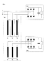
- Fig. 1 Eine Schaltungsanordnung zur Reduktion von Oberwellenströmen realisiert mit einem bekannten Drehstromtransformator
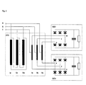
- Fig. 2 Eine Schaltungsanordnung zur Reduktion von Oberwellenströmen realisiert mit einem Spezial-Spar-Drehstromtransformator
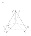
- Fig. 3 Eine Vektor-Darstellung der Funktionsweise des Spezial-Spar-Drehstromtransformators
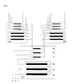
- Fig. 4 Eine Schaltungsanordnung zur vollständigen Reduktion aller Oberwellenströme
- Fig. 1 A circuit arrangement for reducing harmonic currents realized with a known three-phase transformer
- Fig. 2 A circuit arrangement for reducing harmonic currents realized with a special economy three-phase transformer
- Fig. 3 A vector representation of the operation of the special economy three-phase transformer
- Fig. 4 A circuit arrangement for the complete reduction of all harmonic currents
Die Grundlage für das Verfahren zur Reduktion eines Oberwellenstromes mit der Ordnungszahl n liefert die Tatsache, dass bei einer Phasenschiebung der Grundwelle um den Winkel a die n-te Oberwelle um den n-fachen Winkel (n x a) geschoben wird. Für bestimmte Phasenverschiebungen a lassen sich dabei Oberwellenströme eliminieren. Werden z.B. Teile von n x 30° phasenverschobenen Strömen addiert, lassen sich mehrere Oberwellenströme eliminieren. Im Dreiphasensystem lassen sich Phasenverschiebungen um 30° mittels Stern-Dreieck Transformation relativ einfach realisieren.The basis for the method for reducing a harmonic current with the atomic number n is provided by the fact that when the fundamental wave is shifted in phase by the angle a, the nth harmonic is shifted by the n-fold angle (n x a). For certain phase shifts a, harmonic currents can be eliminated. E.g. If parts of n x 30 ° phase-shifted currents are added, several harmonic currents can be eliminated. In the three-phase system, phase shifts by 30 ° can be implemented relatively easily using a star-delta transformation.
Fig. 1 zeigt einen durch Versorgungsleitungen R, S, T gespeisten Drehstromtransformator DT1 mit in Dreieck und Stern geschalteten Primär- bzw. Sekundärwicklungen. Die Versorgungsleitungen R, S und T sind einerseits mit den Eckpunkten der primärseitigen Dreieckschaltung und andererseits mit den Anschlüssen einer ersten Gleichrichtereinheit GE1 verbunden. Ferner sind die sekundärseitigen Transformatorwicklungen mit einer weiteren Gleichrichtereinheit GE2 verbunden. Der Aufbau der Gleichrichtereinheiten GE1, GE2 mit sechs Dioden, einem Kondensator und einem Widerstand ist bekannt und wird nachfolgend nicht weiter erläutert. Selbstverständlich können in den erfindungsgemässen Schaltungsanordnungen auch andersartig aufgebaute Gleichrichtereinheiten angewendet bzw. eingebaut werden. Durch die bei dieser Transformatorschaltung typischen Phasenverschiebung der Grundwelle (Harmonische mit der Ordnungszahl 1) zwischen der Eingangs- und Ausgangsspannung des Drehstromtransformators DT1 bzw. zwischen den an den Gleichrichtereinheiten GE1, GE2 anliegenden Spannungen von 30° lassen sich dabei Oberwellenströme mit den Ordnungszahlen 5 und 7 sowie 17 und 19 eliminieren. Die Gleichrichtereinheit GE2 erzeugt sekundärseitig Pulsströme, die gegenüber denjenigen des Gleichrichters GE1 um 30 phasenverschoben sind. Weiter werden die sekundärseitig erzeugten Pulsströme transformiert und auf die entsprechenden Primärwicklungen übertragen. Z.B. durch die Addition der primärseitig auftretenden, von den Gleichrichtereinheiten GE1 bzw. GE2 verursachten Oberwellenströme mit den entsprechenden Phasenverschiebungen kann leicht nachgewiesen werden, dass sich diese Spannungen gegeneinander aufheben. Mathematisch lässt sich mit der diskreten Fouriertransformation zeigen, dass dadurch Oberwellenströme der Ordnungszahlen 5, 7, 17 und 19 eliminiert werden. Ferner können z.B. die transformierten Oberwellenströme ip, illp, die von der Gleichrichtereinheit GE2 verursacht und in die Primärwicklungen lp, Ilp induziert werden, zu dem von der Gleichrichtereinheit GE1 verursachten Oberwellenstrom iR addiert werden. Für die Oberwellenströme der Ordnungszahl n wird der Strom iR der Gleichrichtereinheit GE1 in der Phase R : iR = A sin (n wt). Der Strom des Gleichrichters GE2 wird aufgeteilt und transformiert. Die zwei resultierenden Komponenten ip, illp, die sich zum Strom iR in der Phase R addieren, sind:
- iIp = B sin (n(wt-a)) und iIIp = -B sin (n(wt-a-120°)) bzw. für a = 30°:
- iIp = B sin (n (wt-30°)) und iIIp = -B sin (n(wt-150°)).
- i Ip = B sin (n (wt-a)) and i IIp = -B sin (n (wt-a-120 °)) or for a = 30 °:
- i Ip = B sin (n (wt-30 °)) and i IIp = -B sin (n (wt-150 °)).
Der zweite Teilstrom iIIp ist wegen dem Wicklungssinn negativ und zusätzlich um -120° (Phase T) verschoben. Die Addition der beiden Teilströme:
- ilp + iIIp = 2B sin (n wt-n 90 + 90°) cos (n 60° - 90°)
wird für n = 5, 7, 17 und 19 unter Berücksichtigung des Übersetzungsverhältnisses(B = A/31/2):
- i l p + i IIp = 2B sin (n wt-n 90 + 90 °) cos (n 60 ° - 90 °)
for n = 5, 7, 17 and 19 taking into account the gear ratio (B = A / 3 1/2 ):
Die Addition aller Oberwellenströme für n = 6 +/-1 + k x 12 (k = 0, 1, 2...) ergibt daher:![]()
![]()
Die Variablen A, B stehen dabei für die Amplituden der genannten Ströme iR bzw. iIp, illp; die Variable w entspricht der Kreisfrequenz der Grundwelle. Für eine festgelegte Ordnungszahl n wird die Phasenverschiebung a zwischen den an die Gleichrichtereinheiten GE1 bzw. GE2 abgegebenen Spannungen jeweils derart gewählt, dass sich die Teilströme iR, iIp, iIIp gegenseitig aufheben. Die Oberwellenströme mit der Ordnungszahl n heben sich dann auf bzw. ergänzen sich zu einem Wechselstrom, dessen Hauptkomponente die Frequenz der Grundwelle aufweist. Durch diesen Sachverhalt wird auch der Leistungsfaktor verbessert, mit dem elektrische Leistung an die Verbraucher abgegeben wird. Die Leistungsentnahme über die Gleichrichtereinheiten GE1, GE2 muss dabei natürlich derart gewählt werden, dass die störenden Oberwellenströme am Eingang der Gleichrichtereinheiten GE1 bzw. GE2 die gleiche Amplitude und die gleiche Form aufweisen. Dadurch wird die vollständige Reduktion dieser Oberwellenströme gewährleistet. Die korrekte Phasenschiebung a kann natürlich auch durch fachmännische Messung im Labor ermittelt werden. D.h. durch kontinuierliche Vergrösserung des Wertes für die Phasenschiebung a wird ermittelt, bei welchen Werten für a welche Oberwellenströme ausgelöscht werden. Bei kleineren Werten für a werden dabei Oberwellenströme mit höherer Ordnungszahl eliminiert. Möglichkeiten zur Abgabe von phasenverschobenen Spannungen an Gleichrichtereinheiten ergeben sich natürlich auch durch Transformatoren mit anderer Schaltung von Primär-und Sekundärwicklungen. So kann z.B. ein Transformator, dessen Primärwicklungen in Stern oder Dreieck geschaltet sind, sekundärseitig drei in Stern und drei in Dreieck geschaltete Sekundärwicklungen aufweisen. Funktionell gleichwertig dazu ist die Verwendung von zwei oder mehr Transformatoren, die sekundärseitig eine Dreieck- bzw.- eine Sternschaltung aufweisen. Über die sekundärseitigen Stern- bzw. Dreieckschaltungen werden dabei wiederum phasenverschobene Spannungen an mindestens zwei Gleichrichtereinheiten GE abgegeben. Bei der Verwendung eines Stern-Dreieck-Transformators zur Phasenschiebung ist jedoch nachteilig, dass über den Drehstromtransformator DT1 die vollständige Scheinleistung übertragen werden muss, was eine entsprechende Dimensionierung des Drehstromtransformators DT1 bedingt. Ferner lässt sich der Wert der Phasenschiebung a nicht beliebig verändern.The variables A, B stand for the amplitudes of the currents i R and i Ip , i ll p; the variable w corresponds to the angular frequency of the fundamental wave. For a predetermined atomic number n, the phase shift a between the voltages delivered to the rectifier units GE1 and GE2 is chosen in such a way that the partial currents i R , i Ip , i IIp cancel each other out. The harmonic currents with the atomic number n then cancel each other out or complement each other to form an alternating current, the main component of which has the frequency of the fundamental wave. This also improves the power factor with which electrical power is delivered to the consumer. The power consumption via the rectifier units GE1, GE2 must of course be selected in such a way that the disturbing harmonic currents at the input of the rectifier units GE1 and GE2 have the same amplitude and the same shape. This ensures the complete reduction of these harmonic currents. The correct phase shift a can of course also be determined by professional measurement in the laboratory. That is, by continuously increasing the value for the phase shift a, it is determined at which values for a which harmonic currents are extinguished. With smaller values for a, harmonic currents with a higher atomic number are eliminated. Of course, possibilities for delivering phase-shifted voltages to rectifier units also result from transformers with a different connection of primary and secondary windings. For example, a transformer whose primary windings are connected in star or delta can have three secondary windings connected in star and three in delta on the secondary side. The use of two or more transformers with a delta or star connection on the secondary side is functionally equivalent. In this case, phase-shifted voltages are in turn output to at least two rectifier units GE via the star or delta connections on the secondary side. When using a star-delta transformer for phase shifting, however, it is disadvantageous that the full apparent power must be transmitted via the three-phase transformer DT1, which necessitates a corresponding dimensioning of the three-phase transformer DT1. Furthermore, the value of the phase shift a cannot be changed arbitrarily.
In Fig. 2 sind die Versorgungsleitungen R, S, T einerseits mit den in Dreieckschaltung zusammengefügten Primär- lp, Illp, Ilp und den Mittelanzapfungen der Sekundärwicklungen Ills, Ils, Is eines Drehstromtransformators DT2 verbunden. D.h. die Versorgungsleitung R ist mit der Primär- und der Sekundärwicklung Ip bzw. Ills verbunden. Durch die angegebene Beschaltung des Drehstromtransformators DT2 ergeben sich Spannungen ux, vy, wz in den Sekundärwicklungen Ills, Ils, Is, deren Vektoren senkrecht zu den Vektoren der Spannungen stehen, die über die Versorgungsleitungen R, S, T den entsprechenden Mittelanzapfungen der Sekundärwicklungen Ills, Ils, Is zugeführt werden. Die oberen und die unteren Anschlüsse der Sekundärwicklungen Is, Ils, Ills sind ferner mit Gleichrichtereinheiten GE3 bzw. GE4 verbunden.In FIG. 2, the supply lines R, S, T are connected on the one hand to the primary lp, illp, ilp connected in a delta connection and the center taps of the secondary windings ills, ils, is of a three-phase transformer DT2. I.e. the supply line R is connected to the primary and secondary windings Ip and Ills. The specified wiring of the three-phase transformer DT2 results in voltages ux, vy, wz in the secondary windings Ills, Ils, Is, the vectors of which are perpendicular to the vectors of the voltages which, via the supply lines R, S, T, the corresponding center taps of the secondary windings Ills, Ils, Is fed. The upper and lower connections of the secondary windings Is, Ils, Ills are also connected to rectifier units GE3 and GE4.
Die Vektoren der vom Drehstromtransformator DT2 an die Gleichrichtereinheiten GE3 bzw. GE4 abgegebenen Spannungen uvw, xyz sind in Fig. 3 aufgezeichnet. Dabei ist leicht ersichtlich, dass der Vektor der Spannung der Versorgungsleitung R senkrecht zum Vektor der Spannung an der Sekundärwicklung Ills steht und mit ihm in der Mitte verbunden ist. Die Vektoren der Spannungen der Primär- und Sekundärwicklungen lp, Is; Ilp, Ils; Illp, Ills stehen parallel zueinander. Wird die Übersetzung wieder so gewählt, dass die an die Gleichrichtereinheiten GE3 bzw. GE4 abgegebenen Spannungen uvw, xyz bzw. deren Grundwellen um 30° phasenverschoben sind, ergibt sich eine andere Addition der pulsförmigen Ströme der Gleichrichtereinheiten GE3 und GE4. Wiederum werden jedoch Oberwellenströme mit den Ordnungszahlen 5, 7, 17 und 19 eliminiert. Ferner können auch mehr als zwei Gleichrichtereinheiten GE an den Drehstromtransformator DT2 angeschlossen werden. So können z.B. drei Gleichrichtereinheiten GE vorgesehen werden, die mit Phasenverschiebungen von 0 und +/-a/2 relativ zu den Versorgungsspannungen angesteuert werden. Es können natürlich auch an weiteren vorzugsweise symmetrisch an den Sekundärwicklungen (ls, Ils, Ills) vorgesehenen Anzapfungen Gleichrichtereinheiten GE angeschaltet werden.
Nebst der leichten Änderbarkeit der relativen Phasenverschiebung und der Amplituden der Spannungen uvw, xyz ergibt sich bei der Verwendung eines Drehstromtransformators wie er in Fig. 3 gezeigt wird auch der Vorteil, dass nur ein Bruchteil der Scheinleistung über den Drehstromtransformator DT2 übertragen werden muss, wobei die Scheinleistung auf der Primärseite kleiner ist als auf der Sekundärseite. Der Drehstromtransformator DT2 ist im vorliegenden Fall hauptsächlich darauf ausgelegt, die gewünschte Phasenverschiebung a zu erzeugen.The vectors of the voltages uvw, xyz output from the three-phase transformer DT2 to the rectifier units GE3 and GE4 are recorded in FIG. 3. It can easily be seen that the vector of the voltage of the supply line R is perpendicular to the vector of the voltage on the secondary winding Ills and is connected to it in the middle. The vectors of the voltages of the primary and secondary windings lp, Is; Ilp, Ils; Illp, Ills are parallel to each other. If the translation is chosen again so that the voltages uvw, xyz or their fundamental waves delivered to the rectifier units GE3 and GE4 or their fundamental waves are phase-shifted, a different addition of the pulsed currents of the rectifier units GE3 and GE4 results. Again, harmonic currents with atomic numbers 5, 7, 17 and 19 are eliminated. Furthermore, more than two rectifier units GE can be connected to the three-phase transformer DT2. For example, three rectifier units GE can be provided, which are controlled with phase shifts of 0 and +/- a / 2 relative to the supply voltages. Of course, rectifier units GE can also be connected to further taps preferably provided symmetrically on the secondary windings (IS, ILS, ILS).
In addition to the easy changeability of the relative phase shift and the amplitudes of the voltages uvw, xyz, the use of a three-phase transformer as shown in FIG. 3 also has the advantage that only a fraction of the apparent power has to be transmitted via the three-phase transformer DT2, the Apparent power is smaller on the primary side than on the secondary side. The three-phase transformer DT2 in the present case is mainly designed to generate the desired phase shift a.
Wenn nach einer ersten Reduktion der kritischen Oberwellenströme weitere Oberwellenströme eliminiert werden sollen, so können, wie in Fig. 4 gezeigt, mehrere Drehstromtransformatoren DTa, DTb, DTc kaskadenartig zusammengeschaltet werden. Falls durch Verwendung von zwei Drehstromtransformatoren DTa, DTb z.B. die Oberwellenströme mit den Ordnungszahlen 5, 7, 17 und 19 eliminiert wurden, können verbleibende störende Oberweilenströme in einem weiteren Schritt durch Zuschaltung des Drehstromtransformators DTc eliminiert werden. Die Phasenverschiebung a in diesem Transformator wird dann entsprechend der festgelegten Ordnungszahlen gewählt, so z.B. 15° für die Unterdrückung der Oberwellenströme mit den Ordnungszahlen 11, 13, 23 und 25.If, after a first reduction of the critical harmonic currents, further harmonic currents are to be eliminated, then, as shown in FIG. 4, a plurality of three-phase transformers DTa, DTb, DTc can be cascaded together. If, by using two three-phase transformers DTa, DTb e.g. the harmonic currents with the atomic numbers 5, 7, 17 and 19 have been eliminated, remaining disturbing harmonic currents can be eliminated in a further step by connecting the three-phase transformer DTc. The phase shift a in this transformer is then selected according to the specified ordinal numbers, e.g. 15 ° for the suppression of harmonic currents with atomic numbers 11, 13, 23 and 25.
Claims (9)
Applications Claiming Priority (2)
| Application Number | Priority Date | Filing Date | Title |
|---|---|---|---|
| CH282090A CH680888A5 (en) | 1990-08-30 | 1990-08-30 | |
| CH2820/90 | 1990-08-30 |
Publications (1)
| Publication Number | Publication Date |
|---|---|
| EP0472928A1 true EP0472928A1 (en) | 1992-03-04 |
Family
ID=4242323
Family Applications (1)
| Application Number | Title | Priority Date | Filing Date |
|---|---|---|---|
| EP91112660A Ceased EP0472928A1 (en) | 1990-08-30 | 1991-07-27 | Circuit arrangement to reduce harmonic currents |
Country Status (2)
| Country | Link |
|---|---|
| EP (1) | EP0472928A1 (en) |
| CH (1) | CH680888A5 (en) |
Cited By (3)
| Publication number | Priority date | Publication date | Assignee | Title |
|---|---|---|---|---|
| EP0584660A2 (en) * | 1992-08-18 | 1994-03-02 | Siemens Schweiz AG | Method and circuit arrangement for reduction of harmonics |
| WO2005119892A1 (en) | 2004-06-04 | 2005-12-15 | Wärtsilä Automation Norway As | Low loss propulsion system |
| EP1715572A2 (en) * | 2005-04-20 | 2006-10-25 | Siemens Aktiengesellschaft | Method of operating an electrical device |
Citations (3)
| Publication number | Priority date | Publication date | Assignee | Title |
|---|---|---|---|---|
| CH364302A (en) * | 1958-10-06 | 1962-09-15 | Oerlikon Maschf | High current rectifier system |
| US3448286A (en) * | 1963-10-31 | 1969-06-03 | Asea Ab | Balancing of harmonics at converter stations in asymmetrical working |
| GB2001486A (en) * | 1977-07-25 | 1979-01-31 | Foster Transformers Ltd | Improvements in rectifiers |
-
1990
- 1990-08-30 CH CH282090A patent/CH680888A5/de not_active IP Right Cessation
-
1991
- 1991-07-27 EP EP91112660A patent/EP0472928A1/en not_active Ceased
Patent Citations (3)
| Publication number | Priority date | Publication date | Assignee | Title |
|---|---|---|---|---|
| CH364302A (en) * | 1958-10-06 | 1962-09-15 | Oerlikon Maschf | High current rectifier system |
| US3448286A (en) * | 1963-10-31 | 1969-06-03 | Asea Ab | Balancing of harmonics at converter stations in asymmetrical working |
| GB2001486A (en) * | 1977-07-25 | 1979-01-31 | Foster Transformers Ltd | Improvements in rectifiers |
Non-Patent Citations (1)
| Title |
|---|
| SOVIET INVENTIONS ILLUSTRATED, Section X12, week 8651, 31 december 1986. Derwent Publications Ltd., London GB * |
Cited By (7)
| Publication number | Priority date | Publication date | Assignee | Title |
|---|---|---|---|---|
| EP0584660A2 (en) * | 1992-08-18 | 1994-03-02 | Siemens Schweiz AG | Method and circuit arrangement for reduction of harmonics |
| EP0584660A3 (en) * | 1992-08-18 | 1994-08-31 | Siemens Ag Albis | |
| WO2005119892A1 (en) | 2004-06-04 | 2005-12-15 | Wärtsilä Automation Norway As | Low loss propulsion system |
| US7514898B2 (en) | 2004-06-04 | 2009-04-07 | Wartsila Norway As | Low loss propulsion system |
| CN100492832C (en) * | 2004-06-04 | 2009-05-27 | 瓦尔茨雷挪威公司 | Propulsion power system |
| EP1715572A2 (en) * | 2005-04-20 | 2006-10-25 | Siemens Aktiengesellschaft | Method of operating an electrical device |
| EP1715572A3 (en) * | 2005-04-20 | 2010-01-13 | Siemens Aktiengesellschaft | Method of operating an electrical device |
Also Published As
| Publication number | Publication date |
|---|---|
| CH680888A5 (en) | 1992-11-30 |
Similar Documents
| Publication | Publication Date | Title |
|---|---|---|
| EP0212172B1 (en) | Current oscillations compensation method and device | |
| DE2644767C3 (en) | Circuit arrangement for a ripple control receiver | |
| DE3525877A1 (en) | NOISE PROTECTION FILTER | |
| DE3139340C2 (en) | ||
| DE2825240C2 (en) | Ripple control system | |
| DE2814320C2 (en) | X-ray diagnostic generator with an inverter circuit that feeds its high-voltage transformer from a mains rectifier and has two inverters | |
| DE2500065A1 (en) | Power pack for electric equipment - has detector generating voltage proportional to that at the transformer primary winding | |
| DE2159030A1 (en) | Converter arrangement | |
| DE3223409A1 (en) | FEEDING SYSTEM | |
| DE2809860A1 (en) | VOLTAGE SYMMETRATOR | |
| DE3700495A1 (en) | SUPPLY DEVICE FOR A WAVE GENERATOR FOR AN IMPULSE RADAR | |
| EP0472928A1 (en) | Circuit arrangement to reduce harmonic currents | |
| EP0584660B1 (en) | Method and circuit arrangement for reduction of harmonics | |
| DE3130958A1 (en) | DC CONVERTER | |
| DE4004412A1 (en) | DC to DC voltage converter | |
| DE2923341C2 (en) | Multiphase electronic electricity meters | |
| DE2155903A1 (en) | Arrangement for eliminating the unbalance or instability of a voltage | |
| DE3345036A1 (en) | CIRCUIT ARRANGEMENT FOR MEASURING THE ANODE CURRENT IN A PARTICULARLY SYMMETRICALLY OPERATED X-RAY PIPE | |
| DE2020264A1 (en) | Polyphase network voltage stabilizer arrangement | |
| DE10108431A1 (en) | Circuit for converting AC voltage to DC voltage | |
| DE674926C (en) | Frequency converter | |
| DE2311534C3 (en) | Filter arrangement for a converter circuit arranged between a three-phase network and a direct current network | |
| DE4012307A1 (en) | Mains power=pack supplying DC loads - has central converter stepping up mains frequency and supplying separate rectifiers for each module of system | |
| DE19611418C1 (en) | Method for specifying a predetermined output impedance of an output circuit of an inverter | |
| EP1017157A2 (en) | Method for the control of a non-harmonic network current portion of a converter, and device for carrying out the method |
Legal Events
| Date | Code | Title | Description |
|---|---|---|---|
| PUAI | Public reference made under article 153(3) epc to a published international application that has entered the european phase |
Free format text: ORIGINAL CODE: 0009012 |
|
| 17P | Request for examination filed |
Effective date: 19910808 |
|
| AK | Designated contracting states |
Kind code of ref document: A1 Designated state(s): AT BE CH DE DK ES FR GB GR IT LI LU NL SE |
|
| 17Q | First examination report despatched |
Effective date: 19931111 |
|
| STAA | Information on the status of an ep patent application or granted ep patent |
Free format text: STATUS: THE APPLICATION HAS BEEN REFUSED |
|
| 18R | Application refused |
Effective date: 19950910 |