EP0472626B1 - Optisches muster - Google Patents
Optisches muster Download PDFInfo
- Publication number
- EP0472626B1 EP0472626B1 EP90908567A EP90908567A EP0472626B1 EP 0472626 B1 EP0472626 B1 EP 0472626B1 EP 90908567 A EP90908567 A EP 90908567A EP 90908567 A EP90908567 A EP 90908567A EP 0472626 B1 EP0472626 B1 EP 0472626B1
- Authority
- EP
- European Patent Office
- Prior art keywords
- disc
- discs
- stencil
- window
- variable optical
- Prior art date
- Legal status (The legal status is an assumption and is not a legal conclusion. Google has not performed a legal analysis and makes no representation as to the accuracy of the status listed.)
- Expired - Lifetime
Links
- 230000003287 optical effect Effects 0.000 title claims abstract description 34
- 230000000712 assembly Effects 0.000 claims description 3
- 238000000429 assembly Methods 0.000 claims description 3
- 230000001419 dependent effect Effects 0.000 claims description 2
- 238000004806 packaging method and process Methods 0.000 description 3
- 235000013305 food Nutrition 0.000 description 2
- 238000004519 manufacturing process Methods 0.000 description 2
- 206010034972 Photosensitivity reaction Diseases 0.000 description 1
- 238000002508 contact lithography Methods 0.000 description 1
- 230000002452 interceptive effect Effects 0.000 description 1
- 238000007648 laser printing Methods 0.000 description 1
- 238000007639 printing Methods 0.000 description 1
Images
Classifications
-
- B—PERFORMING OPERATIONS; TRANSPORTING
- B41—PRINTING; LINING MACHINES; TYPEWRITERS; STAMPS
- B41J—TYPEWRITERS; SELECTIVE PRINTING MECHANISMS, i.e. MECHANISMS PRINTING OTHERWISE THAN FROM A FORME; CORRECTION OF TYPOGRAPHICAL ERRORS
- B41J2/00—Typewriters or selective printing mechanisms characterised by the printing or marking process for which they are designed
- B41J2/435—Typewriters or selective printing mechanisms characterised by the printing or marking process for which they are designed characterised by selective application of radiation to a printing material or impression-transfer material
- B41J2/465—Typewriters or selective printing mechanisms characterised by the printing or marking process for which they are designed characterised by selective application of radiation to a printing material or impression-transfer material using masks, e.g. light-switching masks
- B41J2/4655—Typewriters or selective printing mechanisms characterised by the printing or marking process for which they are designed characterised by selective application of radiation to a printing material or impression-transfer material using masks, e.g. light-switching masks using character templates
Definitions
- the present invention relates to an optical stencil or mask for displaying information or data, and more especially to a variable optical stencil in which each of the characters or elements comprising the information or data displayed by the stencil can be varied.
- Optical stencils are used in laser printing systems for non-contact printing of information or data, usually in the form of alpha-numeric characters. These systems have a wide range of applications, and by way of illustration they are commonly used for printing batch numbers, sell-by dates, serial numbers on the packaging of food products, household products and the like. As will be readily appreciated the unique nature of this information means that it is not usually possible to preprint it on the product packaging, and instead, it is printed on the product packaging at some point in the production process.
- laser light is directed through the stencil and focussed onto a surface of the target object to be printed where the image displayed by the stencil is reproduced either by burning or by a photo-sensitive reaction to the incident laser light.
- the size of the printed image is dependent upon the stencil and the focussing system used.
- variable optical stencils which comprise a plurality of independently driven discs, each of which carries around its periphery a full compliment of the characters or elements to be displayed at a particular position in the stencil.
- Each character or element lies in a respective window or cut-out in the surface of the disc and the characters from each disc all occupy a unique position in their window relative to that of the characters from the other discs.
- variable stencil with more than four characters be required complications arise.
- One solution is to "pair up" each additional disc required to increase the number of characters in the variable stencil with one of the four original discs and drive each disc of the pair via belts or gears and co-axial drive shafts.
- this adds considerably to the cost and complexity of the variable stencil and also introduces other problems such as gear back lash introducing errors, and gear friction increasing the motor load.
- each drive motor In order to continuously determine the relative position of each disc it is known to provide each drive motor with a shaft mounted encoder. However, these have the disadvantage of being bulky and expensive. Furthermore, should the disc slip on the shaft this can not be detected.
- each disc may incorporate its own encoder in the form of a series of unique patterns of slots, each of which is associated with a respective one of the characters on the disc and each of which extends radially from the centre of the disc.
- These slot patterns form a series of concentric rings in the disc, e.g. a 6-bit encoder would have six concentric rings. Whilst this arrangement is perfectly satisfactory in use, it does greatly increase the cost of manufacture of each disc.
- variable optical stencil assembly comprising a plurality of discs, each being of substantially equal diameter and each comprising a plurality of windows disposed around the periphery thereof, each window having at least one character therein, and drive means whereby each disc is independently rotatably driven about a respective axis of rotation, characterised in that there are not less than three discs and not more than five discs in the assembly and each disc partially overlaps each of the other discs at a central point between the axes of rotation, such that a window from each disc is aligned with a window from each of the other discs, and the drive means to each of the discs are all located on the same side of the assembly.
- the discs are so arranged relative to one another as to ensure that their edges overlap at a central point between the axes of rotation without interfering with the drive means of each disc. To this end the distance between any two axes of rotation must be greater than the radius of the discs plus the diameter of the discs central hub. Alignment of the windows is ensured by appropriate selection of the angle of the windows on each disc relative to the radial line running therethrough.
- the assembly comprises four discs which are arranged so that a square may be drawn between their respective axes of rotation.
- the windows of each disc are preferably at an angle of 45 degrees to a radial line drawn through each one.
- the angle can be varied between 0 degrees to 90 degrees, subject to the requirement that the angle of each window to the radial line therethrough must compliment the angle of each window to the radial line therethrough of the disc diagonally opposite it, and the angle to the radial line of each window of each of the other discs must be equal to, but the negative of, the angle of each window of a respective one of the first two discs.
- the windows of one disc are at 30 degrees to the radial lines passing therethrough.
- the windows of the disc diagonally opposite must be at 60 degrees to the radial lines passing therethrough, and the windows of the other two discs must be at -60 degrees and -30 degrees respectively to the radial lines passing therethrough.
- variable optical stencil assembly further comprises resetting means whereby each of the discs can be returned to a datum position.
- the resetting means comprises a datum slot in each disc and an optical sensor associated with each disc which is capable of detecting when the slot is aligned with it.
- variable characters can be further increased without any need to provide complex co-axial drive arrangements by placing two of the assemblies according to the present invention face to face.
- a variable optical stencil with between six to ten discs, each independently rotatably driven by its own drive means. In the unlikely event that yet more discs are required it would be necessary to resort to the use of a co-axial drive shafts and similar arrangements.
- each disc has a concentric ring of slots therein, the radius of which is equal to the distance from the axis of rotation of the datum slot carried by the facing disc.
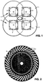
- a variable optical stencil assembly comprising four discs 1, each of which is rotatably driven about its central axis by a stepper motor 2.
- the discs 1 are arranged so that the central axis of each one lies on the corner of a square drawn between the four central axes, and all four discs 1 overlap one another at the centre of this square.
- a plurality of windows 3 are provided around the periphery of each disc 1 and within each window there is provided a particular character of a set of characters which are to be used in the information displayed by the stencil.
- each character occupies the penultimate position of eight character spaces provided in the window and the disc is intended for use in an eight variable character stencil comprising a total of eight discs in all.
- the characters occupy a respective position in this eight character space window.
- Each window 3 is arranged at an angle of 45 degrees to the radial line running through it from the centre of the disc.
- An eight variable character stencil using the disc shown in Fig. 2, and seven others is provided by placing two of the four disc variable optical assemblies shown in Fig. 1 face to face.
- each disc 1 In use, it will occasionally be necessary to return each disc 1 to a datum position and to this end a datum slot 4 is provided in the surface of each disc 1, as shown in Fig. 2.
- an optical sensor (not shown) is fixed in position relative to the disc 1 and by using the output of the optical sensor to regulate the disc drive motor 2 it is possible to stop the disc 1 with the datum slot 4 positioned in alignment with the optical sensor.
- each disc 1 will, of course, be obscured from the optical sensor associated therewith by the disc 1 directly facing it.
- a concentric ring of slots 5 is provided in each disc 1.
- the radius of the ring 5 is equal to the distance of the optical sensor associated with the facing disc 1 from the centre of the disc 1 in which the ring is provided.
- the discs 1 are shown arranged to form a square between their axes of rotation and the windows are at 45 degrees to the radial line running through each, other configurations are possible with the scope of the present invention.
- the angle of the windows may be varied with respect of the radial line, provided that the windows of all four discs align at the point where the discs overlap.
- the discs need not form a square, though this is preferable. Any quadrangle in which the sides are greater in length than the radius of the discs plus the diameter of the central hub, but the distance between opposite corners is less than the diameter of a disc will enable the assembly to operate efficiently.
- the present invention also envisages a five disc variable optical stencil assembly.
- the discs are so arranged that the central axis of each one lies on the corner of a pentagon drawn between the five central axes.
- the length of each side of the pentagon must be greater than the radius of each disc plus the diameter of its central hub, but the distance between any pair of opposite corners must be less than the diameter of each disc.
- the windows in each disc are so arranged as to ensure that one window from each disc aligns with one window from each of the other discs at the centre of the area defined by the overlapping edges.
- variable characters must be mounted on co-axial drive shafts in the same way as for a known optical stencil.
- control circuitry for the stepper motors is conventional and is not deemed to require detailed explanation herein.
Landscapes
- Printing Plates And Materials Therefor (AREA)
- Holo Graphy (AREA)
- Optical Transform (AREA)
- Prostheses (AREA)
- Optical Record Carriers And Manufacture Thereof (AREA)
- Screen Printers (AREA)
Claims (5)
- Variable optische Schablonenbaugruppe, umfassend eine Mehrzahl von Scheiben (1), wobei jede einen im wesentlichen gleichen Durchmesser hat und jede eine Mehrzahl von Fenstern (3) umfaßt, die um ihre Peripherie angeordnet sind, wobei jedes Fenster (3) wenigstens ein Zeichen enthält, sowie Antriebsmittel (2), womit jede Scheibe (1) unabhängig um eine entsprechende Rotationsachse gedreht wird, dadurch gekennzeichnet, daß nicht weniger als drei Scheiben (1) und nicht mehr als fünf Scheiben (1) in der Baugruppe vorhanden sind und daß jede Scheibe (1) alle anderen Scheiben (1) teilweise an einem Mittelpunkt zwischen den Rotationsachsen überlappt, so daß ein Fenster (3) von jeder Scheibe (1) auf ein Fenster (3) der anderen Scheiben (1) ausgerichtet ist, und daß die Antriebsmittel (2) jeder Scheibe (1) alle auf derselben Seite der Baugruppe angeordnet sind.
- Variable optische Schablonenbaugruppe nach Anspruch 1, umfassend Mittel (4) zum Zurücksetzen jeder Scheibe (1) in eine Bezugsposition.
- Variable optische Schablonenbaugruppe nach Anspruch 2, worin das Mittel zum Zurücksetzen der Scheiben (1) in eine Bezugsposition einen Bezugsschlitz (4) in der Scheibe selbst und einen optischen Sensor umfaßt, der relativ zur Scheibe (1) montiert ist.
- Variable optische Schablonenbaugruppe, umfassend zwei variable optische Schablonenbaugruppen nach einem der Ansprüche 1 bis 3, die gegenüberliegend angeordnet sind.
- Variable optische Schablonenbaugruppe nach Anspruch 4 in Abhängigkeit von Anspruch 3, worin jede Scheibe (1) einen konzentrischen Ring aus darin ausgebildeten Schlitzen (5) umfaßt, wobei der Radius des Ringes dem Abstand der Rotationsachse zum Bezugsschlitz (4) in der gegenüberliegenden Scheibe (1) entspricht.
Applications Claiming Priority (3)
| Application Number | Priority Date | Filing Date | Title |
|---|---|---|---|
| GB8911619 | 1989-05-19 | ||
| GB898911619A GB8911619D0 (en) | 1989-05-19 | 1989-05-19 | An optical stencil |
| PCT/GB1990/000779 WO1990014642A1 (en) | 1989-05-19 | 1990-05-18 | An optical stencil |
Publications (2)
| Publication Number | Publication Date |
|---|---|
| EP0472626A1 EP0472626A1 (de) | 1992-03-04 |
| EP0472626B1 true EP0472626B1 (de) | 1996-08-14 |
Family
ID=10657073
Family Applications (1)
| Application Number | Title | Priority Date | Filing Date |
|---|---|---|---|
| EP90908567A Expired - Lifetime EP0472626B1 (de) | 1989-05-19 | 1990-05-18 | Optisches muster |
Country Status (6)
| Country | Link |
|---|---|
| US (1) | US5335003A (de) |
| EP (1) | EP0472626B1 (de) |
| AT (1) | ATE141427T1 (de) |
| DE (1) | DE69028105T2 (de) |
| GB (1) | GB8911619D0 (de) |
| WO (1) | WO1990014642A1 (de) |
Families Citing this family (12)
| Publication number | Priority date | Publication date | Assignee | Title |
|---|---|---|---|---|
| US6711355B1 (en) * | 2002-10-11 | 2004-03-23 | Eastman Kodak Company | Camera having rotary optical encoder |
| US7951409B2 (en) | 2003-01-15 | 2011-05-31 | Newmarket Impressions, Llc | Method and apparatus for marking an egg with an advertisement, a freshness date and a traceability code |
| US8084712B2 (en) * | 2007-03-16 | 2011-12-27 | TEN Medias LLC | Method and apparatus for laser marking objects |
| US8455030B2 (en) * | 2010-01-20 | 2013-06-04 | Ten Media, Llc | Systems and methods for processing eggs |
| JP5913134B2 (ja) | 2010-01-20 | 2016-04-27 | テン メディア,エルエルシー | 卵および他の物体を処理するシステムおよび方法 |
| US20110177208A1 (en) * | 2010-01-20 | 2011-07-21 | Newmarket Impressions, Llc | Systems and methods for processing eggs |
| US8657098B2 (en) * | 2010-01-20 | 2014-02-25 | Ten Media, Llc | Systems and methods for processing eggs |
| US8455026B2 (en) | 2010-01-20 | 2013-06-04 | Ten Media, Llc | Systems and methods for processing eggs |
| US8823758B2 (en) | 2010-01-20 | 2014-09-02 | Ten Media, Llc | Systems and methods for processing eggs |
| US8499718B2 (en) * | 2010-01-20 | 2013-08-06 | Ten Media, Llc | Systems and methods for processing eggs |
| US8715757B2 (en) * | 2010-01-20 | 2014-05-06 | Ten Media, Llc | Systems and methods for processing eggs |
| US9315317B2 (en) | 2012-02-21 | 2016-04-19 | Ten Media, Llc | Container for eggs |
Family Cites Families (4)
| Publication number | Priority date | Publication date | Assignee | Title |
|---|---|---|---|---|
| US3750539A (en) * | 1970-12-23 | 1973-08-07 | Xerox Corp | Projection stencil assembly |
| US3865031A (en) * | 1973-02-26 | 1975-02-11 | Ibm | Ink spray printer |
| US4323317A (en) * | 1980-05-07 | 1982-04-06 | Shibuya Kogyo Company, Ltd. | Pattern controlling device for laser marker |
| FR2548068B1 (fr) * | 1983-06-29 | 1986-03-21 | Cilas Alcatel | Dispositif de marquage par laser |
-
1989
- 1989-05-19 GB GB898911619A patent/GB8911619D0/en active Pending
-
1990
- 1990-05-18 AT AT90908567T patent/ATE141427T1/de not_active IP Right Cessation
- 1990-05-18 WO PCT/GB1990/000779 patent/WO1990014642A1/en not_active Ceased
- 1990-05-18 EP EP90908567A patent/EP0472626B1/de not_active Expired - Lifetime
- 1990-05-18 DE DE69028105T patent/DE69028105T2/de not_active Expired - Fee Related
-
1991
- 1991-11-14 US US07/776,253 patent/US5335003A/en not_active Expired - Fee Related
Also Published As
| Publication number | Publication date |
|---|---|
| DE69028105D1 (de) | 1996-09-19 |
| WO1990014642A1 (en) | 1990-11-29 |
| EP0472626A1 (de) | 1992-03-04 |
| DE69028105T2 (de) | 1997-01-23 |
| US5335003A (en) | 1994-08-02 |
| ATE141427T1 (de) | 1996-08-15 |
| GB8911619D0 (en) | 1989-07-05 |
Similar Documents
| Publication | Publication Date | Title |
|---|---|---|
| EP0472626B1 (de) | Optisches muster | |
| US4730110A (en) | Shaft position encoder | |
| US3187187A (en) | Photoelectric shaft angle encoder | |
| US6389910B1 (en) | Transmission path torque transducer | |
| US4788422A (en) | High resolution rotary encoder having appositely rotating disks | |
| US4367676A (en) | Postage meter value selecting system | |
| EP1016854B1 (de) | Kodiererplatte für Rotationssensor | |
| US4785688A (en) | Torque limiter for paper feeding device of office machine and the like | |
| US4841297A (en) | Displacement coder | |
| US4660036A (en) | Amplified motion encoder | |
| US5691826A (en) | Transmission mechanism for a scanner | |
| US4246478A (en) | Position detector with two timing disks rotating at different speeds | |
| US4395147A (en) | Daisy wheel printer | |
| US3086199A (en) | Numerical position control system | |
| GB2223575A (en) | Optical position encoder | |
| EP0064963B1 (de) | Entwerter | |
| GB2098549A (en) | Phototypesetter font disk | |
| JPS63168511A (ja) | 光エンコ−ダ | |
| EP0519961B1 (de) | Geber, insbesondere für mechanische zähler | |
| JPH04335107A (ja) | 回転体の角度位置検出装置 | |
| JPS5848124Y2 (ja) | シヤシンシヨクジキニオケル カイテンデイスクガタモジバン | |
| JP2668841B2 (ja) | レーザマーキング用マスクユニット | |
| JPS6021411A (ja) | 光学式ロ−タリ−エンコ−ダ | |
| JPH0431533B2 (de) | ||
| GB1601058A (en) | Angle resolvers |
Legal Events
| Date | Code | Title | Description |
|---|---|---|---|
| PUAI | Public reference made under article 153(3) epc to a published international application that has entered the european phase |
Free format text: ORIGINAL CODE: 0009012 |
|
| 17P | Request for examination filed |
Effective date: 19910910 |
|
| AK | Designated contracting states |
Kind code of ref document: A1 Designated state(s): AT BE CH DE DK ES FR GB IT LI LU NL SE |
|
| 17Q | First examination report despatched |
Effective date: 19940325 |
|
| GRAH | Despatch of communication of intention to grant a patent |
Free format text: ORIGINAL CODE: EPIDOS IGRA |
|
| GRAH | Despatch of communication of intention to grant a patent |
Free format text: ORIGINAL CODE: EPIDOS IGRA |
|
| GRAA | (expected) grant |
Free format text: ORIGINAL CODE: 0009210 |
|
| AK | Designated contracting states |
Kind code of ref document: B1 Designated state(s): AT BE CH DE DK ES FR GB IT LI LU NL SE |
|
| PG25 | Lapsed in a contracting state [announced via postgrant information from national office to epo] |
Ref country code: IT Free format text: LAPSE BECAUSE OF FAILURE TO SUBMIT A TRANSLATION OF THE DESCRIPTION OR TO PAY THE FEE WITHIN THE PRESCRIBED TIME-LIMIT;WARNING: LAPSES OF ITALIAN PATENTS WITH EFFECTIVE DATE BEFORE 2007 MAY HAVE OCCURRED AT ANY TIME BEFORE 2007. THE CORRECT EFFECTIVE DATE MAY BE DIFFERENT FROM THE ONE RECORDED. Effective date: 19960814 Ref country code: NL Free format text: LAPSE BECAUSE OF FAILURE TO SUBMIT A TRANSLATION OF THE DESCRIPTION OR TO PAY THE FEE WITHIN THE PRESCRIBED TIME-LIMIT Effective date: 19960814 Ref country code: DK Effective date: 19960814 Ref country code: CH Effective date: 19960814 Ref country code: AT Effective date: 19960814 Ref country code: LI Effective date: 19960814 Ref country code: ES Free format text: THE PATENT HAS BEEN ANNULLED BY A DECISION OF A NATIONAL AUTHORITY Effective date: 19960814 Ref country code: BE Effective date: 19960814 |
|
| REF | Corresponds to: |
Ref document number: 141427 Country of ref document: AT Date of ref document: 19960815 Kind code of ref document: T |
|
| ET | Fr: translation filed | ||
| REF | Corresponds to: |
Ref document number: 69028105 Country of ref document: DE Date of ref document: 19960919 |
|
| PG25 | Lapsed in a contracting state [announced via postgrant information from national office to epo] |
Ref country code: SE Effective date: 19961114 |
|
| NLV1 | Nl: lapsed or annulled due to failure to fulfill the requirements of art. 29p and 29m of the patents act | ||
| REG | Reference to a national code |
Ref country code: CH Ref legal event code: PL |
|
| PG25 | Lapsed in a contracting state [announced via postgrant information from national office to epo] |
Ref country code: LU Free format text: LAPSE BECAUSE OF NON-PAYMENT OF DUE FEES Effective date: 19970531 |
|
| PLBE | No opposition filed within time limit |
Free format text: ORIGINAL CODE: 0009261 |
|
| STAA | Information on the status of an ep patent application or granted ep patent |
Free format text: STATUS: NO OPPOSITION FILED WITHIN TIME LIMIT |
|
| 26N | No opposition filed | ||
| PGFP | Annual fee paid to national office [announced via postgrant information from national office to epo] |
Ref country code: FR Payment date: 19980511 Year of fee payment: 9 Ref country code: GB Payment date: 19980511 Year of fee payment: 9 |
|
| PGFP | Annual fee paid to national office [announced via postgrant information from national office to epo] |
Ref country code: DE Payment date: 19980522 Year of fee payment: 9 |
|
| PG25 | Lapsed in a contracting state [announced via postgrant information from national office to epo] |
Ref country code: GB Free format text: LAPSE BECAUSE OF NON-PAYMENT OF DUE FEES Effective date: 19990518 |
|
| GBPC | Gb: european patent ceased through non-payment of renewal fee |
Effective date: 19990518 |
|
| PG25 | Lapsed in a contracting state [announced via postgrant information from national office to epo] |
Ref country code: FR Free format text: LAPSE BECAUSE OF NON-PAYMENT OF DUE FEES Effective date: 20000131 |
|
| PG25 | Lapsed in a contracting state [announced via postgrant information from national office to epo] |
Ref country code: DE Free format text: LAPSE BECAUSE OF NON-PAYMENT OF DUE FEES Effective date: 20000301 |
|
| REG | Reference to a national code |
Ref country code: FR Ref legal event code: ST |