EP0472024A2 - Pulse radar system - Google Patents
Pulse radar system Download PDFInfo
- Publication number
- EP0472024A2 EP0472024A2 EP91112964A EP91112964A EP0472024A2 EP 0472024 A2 EP0472024 A2 EP 0472024A2 EP 91112964 A EP91112964 A EP 91112964A EP 91112964 A EP91112964 A EP 91112964A EP 0472024 A2 EP0472024 A2 EP 0472024A2
- Authority
- EP
- European Patent Office
- Prior art keywords
- digital
- channel
- pulse
- analog
- radar system
- Prior art date
- Legal status (The legal status is an assumption and is not a legal conclusion. Google has not performed a legal analysis and makes no representation as to the accuracy of the status listed.)
- Withdrawn
Links
Images
Classifications
-
- G—PHYSICS
- G01—MEASURING; TESTING
- G01S—RADIO DIRECTION-FINDING; RADIO NAVIGATION; DETERMINING DISTANCE OR VELOCITY BY USE OF RADIO WAVES; LOCATING OR PRESENCE-DETECTING BY USE OF THE REFLECTION OR RERADIATION OF RADIO WAVES; ANALOGOUS ARRANGEMENTS USING OTHER WAVES
- G01S13/00—Systems using the reflection or reradiation of radio waves, e.g. radar systems; Analogous systems using reflection or reradiation of waves whose nature or wavelength is irrelevant or unspecified
- G01S13/02—Systems using reflection of radio waves, e.g. primary radar systems; Analogous systems
- G01S13/06—Systems determining position data of a target
- G01S13/08—Systems for measuring distance only
- G01S13/10—Systems for measuring distance only using transmission of interrupted, pulse modulated waves
- G01S13/26—Systems for measuring distance only using transmission of interrupted, pulse modulated waves wherein the transmitted pulses use a frequency- or phase-modulated carrier wave
- G01S13/28—Systems for measuring distance only using transmission of interrupted, pulse modulated waves wherein the transmitted pulses use a frequency- or phase-modulated carrier wave with time compression of received pulses
- G01S13/282—Systems for measuring distance only using transmission of interrupted, pulse modulated waves wherein the transmitted pulses use a frequency- or phase-modulated carrier wave with time compression of received pulses using a frequency modulated carrier wave
Definitions
- the invention relates to a pulse radar system according to the preamble of patent claim 1.
- Pulse compression techniques have been used in pulse radar systems for many years in order to increase the resolution or the transmission power of the radar devices.
- the pulse compression technology also makes it possible to create radar systems that require lower peak transmission power while maintaining the same range.
- the sensitivity or the range can be increased by increasing the available energy per pulse by lengthening the transmission pulses.
- This affects the distance resolution, which is an important radar parameter.
- the distance resolution is directly related to the bandwidth of the radar pulse.
- Pulse compression systems are based on the idea of transmitting long, modulated pulses, but the pulse spectrum has the bandwidth of a signal train with short pulses.
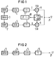
- the arrangement of a digital pulse expander previously used is shown in FIG. 1.
- the expanded signal which is fed to an IF transmission signal output 12, is generated in a single-sideband mixer consisting of two mixing stages 8 and 9.
- the IF carrier frequency is generated in an oscillator 7 and fed to the mixer 8 without a phase shift and to the mixer 9 with a phase shift of 90 degrees via a phase stage 11.
- the I and Q signals in the in-phase channel I and quadrature channel Q are read out from two read-only memories (ROMs) 1 and 2, which are supplied by a counter 3, and in digital / analog converters 4 and 5 implemented.
- a low-pass filter 6 is also interposed between converter 4 and the I-channel input at mixer stage 8.
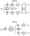
- the arrangement previously used for a digital pulse compressor on the receiving side is shown in FIG. 3.
- the received signal arriving at the IF carrier frequency level at an input 18 is demodulated analogously in two mixing stages 19 and 20.
- the IF oscillator frequency for downmixing is generated in an oscillator 21 and fed to the mixer 19 without a phase shift and to the mixer 20 via a phase link 22 with a 90 degree phase shift.
- This type of demodulation is used in digital signal processing in pulse radar technology Usual in-phase channel I and quadrature channel Q formed.
- the purpose of the quadrature channel is known to be the elimination of the effect of so-called blind phases.
- MI Skolnik pp. 119 to 121.
- the signals in the I-channel and Q-channel are each converted into digital signals in an analog / digital converter 23 or 24 in the baseband position and fed via a low-pass filter 25 or 26 to a complex correlator 27, of which the outputs 28 and 29 the I and Q signals can be taken for evaluation.
- the main problem with the implementation of the known, partly digitally operating pulse compressor is the high computing effort in the complex correlator 27.
- the object of the invention is to simplify the structure, in particular with regard to the reception-side correlator, in a pulse radar system with digital pulse expansion and digital pulse compression, and also to improve the properties as possible, in particular with regard to avoiding quadrature errors on the transmission and reception side.
- FIG. 2 shows a fully digital pulse expander of a pulse radar system according to the invention in a block diagram.
- the sample values of the modulated IF carrier are stored in a read-only memory (ROM) 14 supplied by a counter 13.
- a digital / analog converter 15 therefore generates the IF signal directly without frequency conversion.
- the analog intermediate frequency transmission signal is picked up via a low-pass filter 16 at an output 17.
- the outlay for the fully digital pulse expander shown in FIG. 2 is considerably less than in known digital pulse expander circuits, since only one digital / analog converter 15 is required.
- the level of the intermediate frequency that can be generated depends on the available sampling rate. Carrier frequencies up to approx. 20 MHz are no longer a problem today.
- FIG. 4 shows a fully digital pulse compressor of a pulse radar system according to the invention in block diagram form.
- the received signal picked up in the intermediate frequency level at an input 30 is first fed to an analog / digital converter 31.
- the digitized received signal is then input to a correlator 32 in the IF level.
- Correlator 32 thus no longer works in the baseband but in the carrier frequency level. Since the signals here are purely real, a complex correlator is no longer required. A real correlator is much simpler because it only requires one multiplier and one accumulator per stage.
- the correlated received signal in the IF level is then fed to an input of two digital mixing stages 34 and 35, the second input of which is each loaded by a read-only memory (ROM) 33.
- ROM read-only memory
- the output signals of the two mixer stages 34 and 35 mixed down to the baseband are fed to an output 38 in the I-channel via a low-pass filter 36 and to an output 39 in the Q-channel via a low-pass filter 37.
- the I and Q signals are then available at outputs 38 and 39 for further evaluation.
- An advantage of the fully digital pulse compressor according to FIG. 4 is that only one analog / digital converter 31 is required and that the quadrature errors are eliminated because of the digital quadrature demodulation.
- the processable carrier frequency depends on the level of the available clock rate of analog / digital converters and multipliers.
- carrier frequencies up to approx. 10 MHz can also be processed here, which will certainly be considerably higher in the future.
Landscapes
- Engineering & Computer Science (AREA)
- Radar, Positioning & Navigation (AREA)
- Remote Sensing (AREA)
- Computer Networks & Wireless Communication (AREA)
- Physics & Mathematics (AREA)
- General Physics & Mathematics (AREA)
- Radar Systems Or Details Thereof (AREA)
Abstract
Description
Die Erfindung bezieht sich auf ein Pulsradarsystem gemäß dem Oberbegriff des Patentanspruchs 1.The invention relates to a pulse radar system according to the preamble of patent claim 1.
Pulskompressionstechniken werden seit vielen Jahren bei Pulsradarsystemen eingesetzt, um die Auflösung bzw. die Sendeleistung der Radargeräte zu erhöhen. Durch die Pulskompressionstechnik ist es auch möglich, Radarsysteme zu erstellen, die bei gleichbleibender Reichweite geringere Sendespitzenleistungen benötigen. Bei gepulsten Radarsystemen läßt sich die Empfindlichkeit oder die Reichweite steigern, indem man durch Verlängern der Sendeimpulse die verfügbare Energie pro Impuls erhöht. Darunter leidet allerdings die Distanzauflösung, die ein wichtiger Radarparameter ist. Die Distanzauflösung hängt direkt mit der Bandbreite des Radarpulses zusammen. Pulskompressionssystemen liegt die Idee zugrunde, lange, modulierte Impulse auszusenden, wobei das Pulsspektrum jedoch die Bandbreite eines Signalzuges mit kurzen Impulsen hat.Pulse compression techniques have been used in pulse radar systems for many years in order to increase the resolution or the transmission power of the radar devices. The pulse compression technology also makes it possible to create radar systems that require lower peak transmission power while maintaining the same range. In the case of pulsed radar systems, the sensitivity or the range can be increased by increasing the available energy per pulse by lengthening the transmission pulses. However, this affects the distance resolution, which is an important radar parameter. The distance resolution is directly related to the bandwidth of the radar pulse. Pulse compression systems are based on the idea of transmitting long, modulated pulses, but the pulse spectrum has the bandwidth of a signal train with short pulses.
In üblicher Weise erfolgt heute die Signalverarbeitung analog und zwar unter Anwendung von Oberflächenwellenfiltern (SAW-Filter). Hierbei benötigt man für jedes Kompressionsverhältnis einen eigenen Zweig. Außerdem ist der erreichbare Nebenzipfelabstand bei den auf der Empfangsseite komprimierten Impulsen wegen der Toleranzen der akustischen Oberwellenfilter begrenzt. Analoge Pulskompressionssysteme mit SAW-Filtern sind in dem Aufsatz A. Steffen: "SAW-Pulskompressionssysteme", in der Zeitschrift "Bulletin SEV/VSE Jahrgang 78, Heft 3, 7.2.1987, Seiten 131 bis 135 beschrieben. Auch in dem Buch von M.I. Skolnik: "Introduction to Radar Systems", Second Edition, McGraw-Hill International Book Company, 1981, S. 420 bsi 434 sind verschiedene Möglichkeiten der Pulskompression angegeben.In the usual way, signal processing is carried out today analogously, using surface wave filters (SAW filters). Here you need a separate branch for each compression ratio. In addition, the achievable sub-lobe distance for the pulses compressed on the receiving side is limited because of the tolerances of the acoustic harmonic filters. Analog pulse compression systems with SAW filters are described in the essay A. Steffen: "SAW pulse compression systems", in the magazine "Bulletin SEV / VSE Volume 78, Issue 3, 7.2.1987, pages 131 to 135. Also in the book by MI Skolnik: "Introduction to Radar Systems", Second Edition, McGraw-Hill International Book Company, 1981, p. 420 bsi 434, various possibilities of pulse compression are given.
Unter anderem aus den vorstehend angegebenen Gründen ist man bestrebt, die Pulsexpansion bzw. Pulskompression soweit wie möglich digital zu realisieren. Auch aus dem bereits genannten Aufsatz von A.Steffen ist bereits ein Hinweis zu entnehmen, Pulskompressionssysteme in Betracht der rasanten Fortschritte in der Digitaltechnik ganz oder teilweise digital zu verwirklichen.For the reasons given above, among other things, efforts are being made to digitally implement pulse expansion or pulse compression as far as possible. There is also a hint from A.Steffen's article already mentioned to implement pulse compression systems in whole or in part digitally in view of the rapid advances in digital technology.
Die bisher verwendete Anordnung eines digitalen Pulsexpanders zeigt Figur 1. Das expandierte Signal, das einem Zf-Sendesignalausgang 12 zugeführt wird, wird in einem aus zwei Mischstufen 8 und 9 bestehenden Einseitenbandmischer erzeugt. Die Zf-Trägerfrequenz wird in einem Oszillator 7 erzeugt und der Mischstufe 8 ohne Phasenverschiebung und der Mischstufe 9 mit einer Phasenverschiebung von 90 Grad über eine Phasenstufe 11 zugeführt. Die I- und Q-Signale im In-Phase-Kanal I bzw. Quadraturkanal Q werden aus zwei Festwertspeichern (ROMs) 1 bzw. 2 ausgelesen, die von einem Zähler 3 versorgt werden, und in Digital/Analog-Wandlern 4 bzw. 5 umgesetzt. Zwischen dem Wandler 4 und dem I-Kanaleingang an der Mischstufe 8 ist noch ein Tiefpaß 6 zwischengeschaltet. In gleicher Weise liegt im Q-Kanal zwischen dem Wandler 5 und dem einen Eingang der Mischstufe 9 ein Tiefpaß 7. Die Basisbandsignale können bei dieser Anordnung beliebig genau erzeugt werden. Es bleibt aber der analoge, die beiden Mischstufen 8 und 9 aufweisende Einseitenbandmischer mit seinen Quadraturfehlern.The arrangement of a digital pulse expander previously used is shown in FIG. 1. The expanded signal, which is fed to an IF
Die bisher verwendete Anordnung für einen digitalen Pulskompressor auf der Empfangsseite zeigt Figur 3. Das in der Zf-Trägerfrequenzebene an einem Eingang 18 ankommende Empfangssignal wird in zwei Mischstufen 19 und 20 analog demoduliert. Die Zf-Oszillatorfrequenz zur Herabmischung wird in einem Oszillator 21 erzeugt und der Mischstufe 19 ohne Phasenverschiebung und der Mischstufe 20 über ein Phasenglied 22 mit 90 Grad Phasenverschiebung zugeführt. Durch diese Art von Demodulation werden der in der digitalen Signalverarbeitung in der Pulsradartechnik übliche In-Phase-Kanal I und Quadraturkanal Q gebildet. Der Zweck des Quadraturkanals ist bekanntlich die Eliminierung des Effekts von sogenannten Blindphasen. Im Zusammenhang mit der digitalen Signalverarbeitung bei Pulsradarsystemen wird auf das bereits genannte Buch von M.I. Skolnik, S. 119 bis 121 hingewiesen. Die Signale im I-Kanal und Q-Kanal werden jeweils in einem Analog/Digital-Wandler 23 bzw. 24 in der Basisbandlage in Digitalsignale umgewandelt und über einen Tiefpaß 25 bzw. 26 einem komplexen Korrelator 27 zugeführt, von dem an den Ausgängen 28 und 29 das I- und das Q-Signal zur Auswertung abgenommen werden können. Das Hauptproblem bei der Realisierung des bekannten, z.T. digital arbeitenden Pulskompressors stellt der hohe Rechenaufwand im komplexen Korrelator 27 dar.The arrangement previously used for a digital pulse compressor on the receiving side is shown in FIG. 3. The received signal arriving at the IF carrier frequency level at an
Aufgabe der Erfindung ist es, bei einem Pulsradarsystem mit digitaler Pulsexpansion und digitaler Pulskompression den Aufbau, insbesondere bezüglich des empfangsseitigen Korrelators, zu vereinfachen und dabei auch möglichst die Eigenschaften, insbesondere was eine Vermeidung von Quadraturfehlern auf der Sende- und Empfangsseite betrifft, zu verbessern.The object of the invention is to simplify the structure, in particular with regard to the reception-side correlator, in a pulse radar system with digital pulse expansion and digital pulse compression, and also to improve the properties as possible, in particular with regard to avoiding quadrature errors on the transmission and reception side.
Diese Aufgabe wird bei einer gattungsgemäßen Anordnung durch die im kennzeichnenden Teil des Patentanspruchs 1 angegebenen Merkmale gelöst. Der Schaltungsaufwand auf der Sendeseite ist beim Pulsradarsystem nach der Erfindung wesentlich geringer, da nur ein einziger Digital/Analog-Wandler auf der Sendeseite erforderlich ist. Quadraturfehler können nicht mehr auftreten, da kein Einseitenbandmischer vorhanden ist. Auf der Empfangsseite ist kein komplexer Korrelator mehr erforderlich, sondern nur noch ein wesentlich einfacher aufgebauter reeller Korrelator.This object is achieved in a generic arrangement by the features specified in the characterizing part of patent claim 1. The amount of circuitry on the transmission side is significantly lower in the pulse radar system according to the invention, since only a single digital / analog converter is required on the transmission side. Quadrature errors can no longer occur because there is no single sideband mixer. A complex correlator is no longer required on the receiving side, but only a much simpler real correlator.
Zweckmäßige Weiterbildungen der Erfindung sind in den Unteransprüchen angegeben.Appropriate developments of the invention are specified in the subclaims.
Die Erfindung wird im folgenden anhand von Figuren erläutert.The invention is explained below with reference to figures.
Es zeigen:
- Fig. 1
- den, bekannten bereits vorher beschriebenen sendeseitigen digitalen Pulsexpander in einem Schaltbild,
- Fig. 2
- das Schaltbild eines volldigitalen Pulsexpanders in einem Pulsradarsystem nach der Erfindung
- Fig. 3
- das Blockschaltbild des ebenfalls bereits beschriebenen, bekannten Pulskompressors,
- Fig. 4
- das Blockschaltbild eines volldigitalen Pulskompressors des Pulsradarsystems nach der Erfindung.
- Fig. 1
- the known, previously described transmitter-side digital pulse expander in a circuit diagram,
- Fig. 2
- the circuit diagram of a fully digital pulse expander in a pulse radar system according to the invention
- Fig. 3
- the block diagram of the known pulse compressor, which has also already been described,
- Fig. 4
- the block diagram of a fully digital pulse compressor of the pulse radar system according to the invention.
In Figur 2 ist ein voll digital arbeitender Pulsexpander eines Pulsradarsystems nach der Erfindung im Blockschaltbild dargestellt. In einem von einem Zähler 13 versorgten Festwertspeicher (ROM) 14 sind die Abtastwerte des modulierten Zf-Trägers abgespeichert. Ein Digital/Analog-Wandler 15 erzeugt das Zf-Signal daher direkt ohne Frequenzumsetzung. Abgenommen wird das analoge Zwischenfrequenz-Sendesignal über einen Tiefpaß 16 an einem Ausgang 17. Der Aufwand für den in Figur 2 dargestellten voll digitalen Pulsexpander ist wesentlich geringer als bei bekannten digitalen Pulsexpanderschaltungen, da lediglich ein Digital/Analog-Wandler 15 erforderlich ist. Auch ein Einseitenbandmischer entfällt, weshalb keine Quadraturfehler mehr auftreten können. Die Höhe der erzeugbaren Zwischenfrequenz hängt zwar von der zur Verfügung stehenden Abtastrate ab. Trägerfrequenzen bis ca. 20 MHz stellen heute aber keinerlei Problem mehr dar.FIG. 2 shows a fully digital pulse expander of a pulse radar system according to the invention in a block diagram. The sample values of the modulated IF carrier are stored in a read-only memory (ROM) 14 supplied by a counter 13. A digital / analog converter 15 therefore generates the IF signal directly without frequency conversion. The analog intermediate frequency transmission signal is picked up via a low-
In Figur 4 ist ein voll digital arbeitender Pulskompressor eines Pulsradarsystems nach der Erfindung in Blockschaltbildform dargestellt. Das in der Zwischenfrequenzebene an einem Eingang 30 abgenommene Empfangssignal wird zuerst einem Analog/Digital-Wandler 31 zugeführt. Das digitalisierte Empfangssignal wird in der Zf-Ebene dann einem Korrelator 32 eingegeben. Der Korrelator 32 arbeitet somit nicht mehr im Basisband, sondern in der Trägerfrequenzebene. Da die Signale hier rein reell sind, wird kein komplexer Korrelator mehr benötigt. Ein reeller Korrelator ist wesentlich einfacher aufgebaut, da er pro Stufe nur einen Multiplizierer und einen Akkumulator benötigt. Das korrelierte Empfangssignal in der Zf-Ebene wird dann jeweils einem Eingang zweier digitaler Mischstufen 34 bzw. 35 zugeführt, deren zweiter Eingang jeweils von einem Festwertspeicher (ROM) 33 beaufschlagt wird. Die ins Basisband heruntergemischten Ausgangssignale der beiden Mischstufen 34 und 35 werden im I-Kanal über einen Tiefpaß 36 einem Ausgang 38 und im Q-Kanal über einen Tiefpaß 37 einem Ausgang 39 zugeführt. An den Ausgängen 38 und 39 stehen dann die I- und Q-Signale zur weitern Auswertung bereit.FIG. 4 shows a fully digital pulse compressor of a pulse radar system according to the invention in block diagram form. The received signal picked up in the intermediate frequency level at an
Von Vorteil beim voll digital arbeitenden Pulskompressor nach Fig. 4 ist, daß nur ein Analog/Digital-Wandler 31 benötigt wird und daß wegen der digitalen Quadraturdemodulation die Quadraturfehler entfallen. Auch hier hängt zwar die verarbeitbare Trägerfrequenz von der Höhe der zur Verfügung stehenden Taktrate von Analog/Digital-Wandlern und Multiplizierern ab. Es lassen sich aber auch hier bereits Trägerfrequenzen bis ca. 10 MHz verarbeiten, die in Zukunft sicherlich erheblich höher liegen dürften.An advantage of the fully digital pulse compressor according to FIG. 4 is that only one analog /
Claims (3)
dadurch gekennzeichnet,
daß auf der Sendeseite im Festwertspeicher (14) die Abtastwerte der modulierten Zf-Trägerfrequenz abgespeichert sind und der Digital/Analog-Wandler (15) das Zwischenfrequenzsignal direkt ohne Umsetzung erzeugt,
daß auf der Empfangsseite im Anschluß an die schon in der Zf-Trägerfrequenzebene mittels eines einzigen Analog/Digital-Wandlers (31) durchgeführten Analog/Digital-Umwandlung die Korrelation ebenfalls in der Zf-Trägerfrequenzebene und zwar mittels eines reellen Korrelators (32) vorgenommen wird, und daß auf der Empfangsseite nach der Korrelation eine digitale Quadraturdemodulation mit Aufteilung der korrelierten Signale in den I-Kanal und den Q-Kanal mittels zweier von einem Festwertspeicher (33) beaufschlagter digitaler Mischstufen (34, 35) durchgeführt wird.Pulse radar system with pulse expansion digitally generated on the transmission side, in which the signal curve of the transmission pulses is stored point by point in a read-only memory and output via a digital / analog converter, and with pulse compression generated digitally on the receiving side using a compression filter, after an analog / digital conversion and one Correlation of the received signal with the compression filter response, an evaluation of the signals present in an in-phase channel (I channel) and a quadrature channel (Q channel) takes place,
characterized by
that the samples of the modulated IF carrier frequency are stored in the read-only memory (14) on the transmission side and the digital / analog converter (15) generates the intermediate frequency signal directly without conversion,
that on the receiving side, following the analog / digital conversion already carried out in the IF carrier frequency level by means of a single analog / digital converter (31), the correlation is also carried out in the IF carrier frequency level, namely by means of a real correlator (32) , and that on the receiving side, after the correlation, digital quadrature demodulation with division of the correlated signals into the I channel and the Q channel is carried out by means of two digital mixer stages (34, 35) loaded by a read-only memory (33).
dadurch gekennzeichnet,
daß auf der Sendeseite in der Zf-Ebene im Anschluß an den Digital/Analog-Wandler (15) ein Tiefpaß (16) folgt.Pulse radar system according to claim 1,
characterized by
that a low-pass filter (16) follows on the transmission side in the IF level following the digital / analog converter (15).
dadurch gekennzeichnet,
daß auf der Empfangsseite an den Ausgängen der beiden digitalen Mischstufen (34, 35) jeweils ein Tiefpaß (36, 37) liegt und daß die von den beiden Tiefpässen ausgehenden Signale als I- bzw. Q-Kanal-Signale dann zur Auswertung herangezogen werden.Pulse radar system according to claim 1,
characterized by
that a low-pass filter (36, 37) is located at the outputs of the two digital mixing stages (34, 35) and that the signals emanating from the two low-pass filters are then used as I or Q-channel signals for evaluation.
Applications Claiming Priority (2)
| Application Number | Priority Date | Filing Date | Title |
|---|---|---|---|
| DE4026854 | 1990-08-24 | ||
| DE4026854 | 1990-08-24 |
Publications (2)
| Publication Number | Publication Date |
|---|---|
| EP0472024A2 true EP0472024A2 (en) | 1992-02-26 |
| EP0472024A3 EP0472024A3 (en) | 1992-08-19 |
Family
ID=6412871
Family Applications (1)
| Application Number | Title | Priority Date | Filing Date |
|---|---|---|---|
| EP19910112964 Withdrawn EP0472024A3 (en) | 1990-08-24 | 1991-08-01 | Pulse radar system |
Country Status (1)
| Country | Link |
|---|---|
| EP (1) | EP0472024A3 (en) |
Cited By (4)
| Publication number | Priority date | Publication date | Assignee | Title |
|---|---|---|---|---|
| WO2003092183A2 (en) * | 2002-04-10 | 2003-11-06 | Nanotron Technologies Gmbh | Transceiver device |
| WO2014123433A1 (en) * | 2013-02-07 | 2014-08-14 | BUMAR ELEKTRONIBUMAR Spółka Akcyjna | A method of and a circuit for radar signal compression |
| WO2017063724A1 (en) | 2015-10-16 | 2017-04-20 | Oliver Bartels | Radio-based positioning process with a highly precise delay in the transponder |
| DE102016008390B3 (en) * | 2016-07-09 | 2017-05-24 | Oliver Bartels | Detector for chirp pulses with short latency and high temporal precision |
Citations (5)
| Publication number | Priority date | Publication date | Assignee | Title |
|---|---|---|---|---|
| US3794995A (en) * | 1972-08-02 | 1974-02-26 | Raytheon Co | Modulation signal generator and apparatus using such generator |
| US3852746A (en) * | 1972-11-14 | 1974-12-03 | Raytheon Co | Pulse compression radar |
| EP0080014A2 (en) * | 1981-09-26 | 1983-06-01 | Robert Bosch Gmbh | Digital demodulator for frequency-modulated signals |
| EP0145056A2 (en) * | 1983-12-07 | 1985-06-19 | Hollandse Signaalapparaten B.V. | Digital pulse compression filter |
| US4560961A (en) * | 1983-01-26 | 1985-12-24 | Republic Electronics, Inc. | Method and means for generating pulse compression pulses |
-
1991
- 1991-08-01 EP EP19910112964 patent/EP0472024A3/en not_active Withdrawn
Patent Citations (5)
| Publication number | Priority date | Publication date | Assignee | Title |
|---|---|---|---|---|
| US3794995A (en) * | 1972-08-02 | 1974-02-26 | Raytheon Co | Modulation signal generator and apparatus using such generator |
| US3852746A (en) * | 1972-11-14 | 1974-12-03 | Raytheon Co | Pulse compression radar |
| EP0080014A2 (en) * | 1981-09-26 | 1983-06-01 | Robert Bosch Gmbh | Digital demodulator for frequency-modulated signals |
| US4560961A (en) * | 1983-01-26 | 1985-12-24 | Republic Electronics, Inc. | Method and means for generating pulse compression pulses |
| EP0145056A2 (en) * | 1983-12-07 | 1985-06-19 | Hollandse Signaalapparaten B.V. | Digital pulse compression filter |
Cited By (5)
| Publication number | Priority date | Publication date | Assignee | Title |
|---|---|---|---|---|
| WO2003092183A2 (en) * | 2002-04-10 | 2003-11-06 | Nanotron Technologies Gmbh | Transceiver device |
| WO2003092183A3 (en) * | 2002-04-10 | 2004-03-25 | Nanotron Technologies Gmbh | Transceiver device |
| WO2014123433A1 (en) * | 2013-02-07 | 2014-08-14 | BUMAR ELEKTRONIBUMAR Spółka Akcyjna | A method of and a circuit for radar signal compression |
| WO2017063724A1 (en) | 2015-10-16 | 2017-04-20 | Oliver Bartels | Radio-based positioning process with a highly precise delay in the transponder |
| DE102016008390B3 (en) * | 2016-07-09 | 2017-05-24 | Oliver Bartels | Detector for chirp pulses with short latency and high temporal precision |
Also Published As
| Publication number | Publication date |
|---|---|
| EP0472024A3 (en) | 1992-08-19 |
Similar Documents
| Publication | Publication Date | Title |
|---|---|---|
| DE69826829T2 (en) | DIGITAL COMMUNICATION DEVICE | |
| EP0080014B1 (en) | Digital demodulator for frequency-modulated signals | |
| DE69735335T2 (en) | Removal of the DC offset and suppression of corrupted AM signals in a direct conversion receiver | |
| EP0597255B1 (en) | Receiver for digital audio broadcast with digital signal processing | |
| DE60310569T2 (en) | MIXER ASSEMBLY USING SOME OSCILLATORS AND SYSTEMS BASED ON THE SAME | |
| DE19713102A1 (en) | Integrated receiving circuit for mobile phone | |
| DE3145919A1 (en) | METHOD AND ARRANGEMENT FOR DEMODULATING TIME-DISCRETE FREQUENCY-MODULATED SIGNALS | |
| DE4219417A1 (en) | Narrow-band data signal receiver from long-wave transmitter - employs Hilbert transform to produce in=phase and quadrature signal components for coordinate rotation digital computer. | |
| DE69628130T2 (en) | Digital narrow band filter | |
| EP0472024A2 (en) | Pulse radar system | |
| DE69837002T2 (en) | DELAY COMPENSATING DEVICE OF A LINEARIZING LOOP OF A POWER AMPLIFIER | |
| EP0204849A1 (en) | Circuit arrangement for filtering and demodulating a frequency-modulated signal with at least one sound signal | |
| DE69926064T2 (en) | Three-port structure with modulated injection signal | |
| DE3733967C2 (en) | ||
| DE19934215C1 (en) | Quadrature mixer for HF transmission applications uses analogue demodulator providing feedback signal used for evaluation and correction of offset error for each quadrature component | |
| EP0755125B1 (en) | Method for the reduction of secondary receiving positions in homodyne receivers with time variable carrier frequency | |
| DE10027389B4 (en) | Method of synchronization | |
| DE10000958B4 (en) | Circuit arrangement for generating a quadrature amplitude modulated transmission signal | |
| DE3425782A1 (en) | FM DEMODULATION THROUGH DIGITAL DELAY AND AUTOCORRELATION | |
| EP0499827B1 (en) | Car radio comprising a circuit for Analog/Digital conversion of the IF signal | |
| DE2827422B2 (en) | Method and circuit arrangement for measuring characteristic values of a quadrupole, in particular a data transmission link | |
| DE1932291A1 (en) | Frequency converter | |
| DE3636630C1 (en) | Single channel radio direction finder | |
| DE3428318C2 (en) | ||
| DE2902616A1 (en) | VHF RECEIVER, IN PARTICULAR CAR RECEIVER |
Legal Events
| Date | Code | Title | Description |
|---|---|---|---|
| PUAI | Public reference made under article 153(3) epc to a published international application that has entered the european phase |
Free format text: ORIGINAL CODE: 0009012 |
|
| AK | Designated contracting states |
Kind code of ref document: A2 Designated state(s): DE FR GB IT |
|
| PUAL | Search report despatched |
Free format text: ORIGINAL CODE: 0009013 |
|
| AK | Designated contracting states |
Kind code of ref document: A3 Designated state(s): DE FR GB IT |
|
| 17P | Request for examination filed |
Effective date: 19921007 |
|
| STAA | Information on the status of an ep patent application or granted ep patent |
Free format text: STATUS: THE APPLICATION IS DEEMED TO BE WITHDRAWN |
|
| 18D | Application deemed to be withdrawn |
Effective date: 19940301 |