EP0471930A1 - Method for real time compensation of fluid compressibility in high pressure reciprocating pumps - Google Patents
Method for real time compensation of fluid compressibility in high pressure reciprocating pumps Download PDFInfo
- Publication number
- EP0471930A1 EP0471930A1 EP91109005A EP91109005A EP0471930A1 EP 0471930 A1 EP0471930 A1 EP 0471930A1 EP 91109005 A EP91109005 A EP 91109005A EP 91109005 A EP91109005 A EP 91109005A EP 0471930 A1 EP0471930 A1 EP 0471930A1
- Authority
- EP
- European Patent Office
- Prior art keywords
- pumping
- fluid
- pressure
- flow rate
- piston
- Prior art date
- Legal status (The legal status is an assumption and is not a legal conclusion. Google has not performed a legal analysis and makes no representation as to the accuracy of the status listed.)
- Granted
Links
- 239000012530 fluid Substances 0.000 title claims abstract description 106
- 238000000034 method Methods 0.000 title claims abstract description 12
- 238000005086 pumping Methods 0.000 claims abstract description 78
- 238000007906 compression Methods 0.000 claims abstract description 21
- 230000006835 compression Effects 0.000 claims abstract description 20
- 239000007788 liquid Substances 0.000 claims description 13
- 230000007423 decrease Effects 0.000 claims description 5
- 230000010349 pulsation Effects 0.000 claims description 4
- 238000009530 blood pressure measurement Methods 0.000 claims 1
- 230000000694 effects Effects 0.000 abstract description 5
- 238000010438 heat treatment Methods 0.000 abstract description 3
- 230000002441 reversible effect Effects 0.000 abstract description 2
- 230000004308 accommodation Effects 0.000 abstract 1
- CURLTUGMZLYLDI-UHFFFAOYSA-N Carbon dioxide Chemical compound O=C=O CURLTUGMZLYLDI-UHFFFAOYSA-N 0.000 description 16
- 238000006073 displacement reaction Methods 0.000 description 12
- 229910002092 carbon dioxide Inorganic materials 0.000 description 8
- 230000003247 decreasing effect Effects 0.000 description 5
- 238000010586 diagram Methods 0.000 description 5
- 239000001569 carbon dioxide Substances 0.000 description 4
- 238000012937 correction Methods 0.000 description 4
- 238000004811 liquid chromatography Methods 0.000 description 4
- 238000004808 supercritical fluid chromatography Methods 0.000 description 4
- 230000009977 dual effect Effects 0.000 description 3
- 239000003607 modifier Substances 0.000 description 2
- 238000012544 monitoring process Methods 0.000 description 2
- 239000002904 solvent Substances 0.000 description 2
- 238000004587 chromatography analysis Methods 0.000 description 1
- 125000004122 cyclic group Chemical group 0.000 description 1
- 230000008030 elimination Effects 0.000 description 1
- 238000003379 elimination reaction Methods 0.000 description 1
- 239000007789 gas Substances 0.000 description 1
- 238000009499 grossing Methods 0.000 description 1
- 238000004128 high performance liquid chromatography Methods 0.000 description 1
- 238000002347 injection Methods 0.000 description 1
- 239000007924 injection Substances 0.000 description 1
- 230000014759 maintenance of location Effects 0.000 description 1
- 238000005259 measurement Methods 0.000 description 1
- 238000012986 modification Methods 0.000 description 1
- 230000004048 modification Effects 0.000 description 1
- 238000000926 separation method Methods 0.000 description 1
- 239000000126 substance Substances 0.000 description 1
- 238000012546 transfer Methods 0.000 description 1
Images


Classifications
-
- F—MECHANICAL ENGINEERING; LIGHTING; HEATING; WEAPONS; BLASTING
- F04—POSITIVE - DISPLACEMENT MACHINES FOR LIQUIDS; PUMPS FOR LIQUIDS OR ELASTIC FLUIDS
- F04B—POSITIVE-DISPLACEMENT MACHINES FOR LIQUIDS; PUMPS
- F04B11/00—Equalisation of pulses, e.g. by use of air vessels; Counteracting cavitation
- F04B11/005—Equalisation of pulses, e.g. by use of air vessels; Counteracting cavitation using two or more pumping pistons
- F04B11/0075—Equalisation of pulses, e.g. by use of air vessels; Counteracting cavitation using two or more pumping pistons connected in series
-
- F—MECHANICAL ENGINEERING; LIGHTING; HEATING; WEAPONS; BLASTING
- F04—POSITIVE - DISPLACEMENT MACHINES FOR LIQUIDS; PUMPS FOR LIQUIDS OR ELASTIC FLUIDS
- F04B—POSITIVE-DISPLACEMENT MACHINES FOR LIQUIDS; PUMPS
- F04B49/00—Control, e.g. of pump delivery, or pump pressure of, or safety measures for, machines, pumps, or pumping installations, not otherwise provided for, or of interest apart from, groups F04B1/00 - F04B47/00
- F04B49/06—Control using electricity
- F04B49/065—Control using electricity and making use of computers
-
- F—MECHANICAL ENGINEERING; LIGHTING; HEATING; WEAPONS; BLASTING
- F04—POSITIVE - DISPLACEMENT MACHINES FOR LIQUIDS; PUMPS FOR LIQUIDS OR ELASTIC FLUIDS
- F04B—POSITIVE-DISPLACEMENT MACHINES FOR LIQUIDS; PUMPS
- F04B2201/00—Pump parameters
- F04B2201/02—Piston parameters
- F04B2201/0208—Leakage across the piston
-
- F—MECHANICAL ENGINEERING; LIGHTING; HEATING; WEAPONS; BLASTING
- F04—POSITIVE - DISPLACEMENT MACHINES FOR LIQUIDS; PUMPS FOR LIQUIDS OR ELASTIC FLUIDS
- F04B—POSITIVE-DISPLACEMENT MACHINES FOR LIQUIDS; PUMPS
- F04B2201/00—Pump parameters
- F04B2201/06—Valve parameters
- F04B2201/0605—Leakage over a valve
-
- F—MECHANICAL ENGINEERING; LIGHTING; HEATING; WEAPONS; BLASTING
- F04—POSITIVE - DISPLACEMENT MACHINES FOR LIQUIDS; PUMPS FOR LIQUIDS OR ELASTIC FLUIDS
- F04B—POSITIVE-DISPLACEMENT MACHINES FOR LIQUIDS; PUMPS
- F04B2205/00—Fluid parameters
- F04B2205/03—Pressure in the compression chamber
-
- F—MECHANICAL ENGINEERING; LIGHTING; HEATING; WEAPONS; BLASTING
- F04—POSITIVE - DISPLACEMENT MACHINES FOR LIQUIDS; PUMPS FOR LIQUIDS OR ELASTIC FLUIDS
- F04B—POSITIVE-DISPLACEMENT MACHINES FOR LIQUIDS; PUMPS
- F04B2205/00—Fluid parameters
- F04B2205/05—Pressure after the pump outlet
-
- F—MECHANICAL ENGINEERING; LIGHTING; HEATING; WEAPONS; BLASTING
- F04—POSITIVE - DISPLACEMENT MACHINES FOR LIQUIDS; PUMPS FOR LIQUIDS OR ELASTIC FLUIDS
- F04B—POSITIVE-DISPLACEMENT MACHINES FOR LIQUIDS; PUMPS
- F04B2205/00—Fluid parameters
- F04B2205/09—Flow through the pump
-
- F—MECHANICAL ENGINEERING; LIGHTING; HEATING; WEAPONS; BLASTING
- F04—POSITIVE - DISPLACEMENT MACHINES FOR LIQUIDS; PUMPS FOR LIQUIDS OR ELASTIC FLUIDS
- F04B—POSITIVE-DISPLACEMENT MACHINES FOR LIQUIDS; PUMPS
- F04B2205/00—Fluid parameters
- F04B2205/11—Outlet temperature
-
- G—PHYSICS
- G01—MEASURING; TESTING
- G01N—INVESTIGATING OR ANALYSING MATERIALS BY DETERMINING THEIR CHEMICAL OR PHYSICAL PROPERTIES
- G01N30/00—Investigating or analysing materials by separation into components using adsorption, absorption or similar phenomena or using ion-exchange, e.g. chromatography or field flow fractionation
- G01N30/02—Column chromatography
- G01N30/26—Conditioning of the fluid carrier; Flow patterns
- G01N30/28—Control of physical parameters of the fluid carrier
- G01N30/32—Control of physical parameters of the fluid carrier of pressure or speed
- G01N2030/324—Control of physical parameters of the fluid carrier of pressure or speed speed, flow rate
-
- G—PHYSICS
- G01—MEASURING; TESTING
- G01N—INVESTIGATING OR ANALYSING MATERIALS BY DETERMINING THEIR CHEMICAL OR PHYSICAL PROPERTIES
- G01N30/00—Investigating or analysing materials by separation into components using adsorption, absorption or similar phenomena or using ion-exchange, e.g. chromatography or field flow fractionation
- G01N30/02—Column chromatography
- G01N30/26—Conditioning of the fluid carrier; Flow patterns
- G01N30/28—Control of physical parameters of the fluid carrier
- G01N30/32—Control of physical parameters of the fluid carrier of pressure or speed
- G01N2030/326—Control of physical parameters of the fluid carrier of pressure or speed pumps
-
- G—PHYSICS
- G01—MEASURING; TESTING
- G01N—INVESTIGATING OR ANALYSING MATERIALS BY DETERMINING THEIR CHEMICAL OR PHYSICAL PROPERTIES
- G01N30/00—Investigating or analysing materials by separation into components using adsorption, absorption or similar phenomena or using ion-exchange, e.g. chromatography or field flow fractionation
- G01N30/02—Column chromatography
- G01N30/88—Integrated analysis systems specially adapted therefor, not covered by a single one of the groups G01N30/04 - G01N30/86
- G01N2030/8804—Integrated analysis systems specially adapted therefor, not covered by a single one of the groups G01N30/04 - G01N30/86 automated systems
-
- G—PHYSICS
- G01—MEASURING; TESTING
- G01N—INVESTIGATING OR ANALYSING MATERIALS BY DETERMINING THEIR CHEMICAL OR PHYSICAL PROPERTIES
- G01N30/00—Investigating or analysing materials by separation into components using adsorption, absorption or similar phenomena or using ion-exchange, e.g. chromatography or field flow fractionation
- G01N30/02—Column chromatography
Definitions
- the invention relates to a pumping apparatus for delivering liquid at a high pressure, in particular a pumping apparatus for solvent delivery in liquid chromatography or supercritical fluid chromatography.
- the pumping apparatus pumps a mobile phase and a sample to be separated through the chromatographic system which includes a separation column and various transfer lines.
- the flow rate of the liquid delivered to the column should be adjustable over a wide range. Once adjusted, it is very important to keep the flow rate constant as fluctuations cause variations in the retention time and associated areas under chromatographic peaks generated by chromatographic detectors of the separated sample.
- Flow sensitive detectors used in supercritical fluid or liquid chromatography include RI detectors, dielectric constant detectors, electrical conductivity detectors, NPD, ECD and fluorescence detectors. Since the area under the peaks are representative of the concentration of the chromatographically separated sample substances, fluctuations in the flow rate would impair the accuracy and the reproducibility of quantitative measurements. Additionally, many detectors are sensitive to flow and/or pressure ripples.
- a dual piston pump having two interconnected pump heads each with a reciprocating piston.
- the pistons may be driven via cams and a cam-shaft, a ball-screw drive or any other suitable mechanism which permits a phase difference resulting in a comparatively smooth outflow.
- a dual piston pump driven via cams and a common cam shaft is known from U.S. Pat. No. 4,352,636.
- One type of reciprocating pump which incorporates the ball-screw drive is disclosed in U.S. Patent No. 4,883,409 entitled "Pumping Apparatus for Delivering Liquid at High Pressure", and is hereby incorporated by reference.
- the '409 patent discloses a pumping apparatus having two gear driven pistons which reciprocate in opposite directions in two pump chambers, respectively.
- the pistons are coupled to ball-screw drives which translate the rotary motion of the spindles into a linear motion of the pistons.
- the stroke volume can be changed by changing the amount in which the spindles are rotated during a pump cycle.
- a ball-screw drive permits the selection of any desired piston displacement over time during a pump cycle. For example, the displacement may be varied linearly as a function of time or accelerated for a short time to obtain a pre-compression phase.
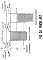
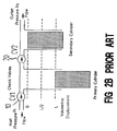
- Figure 2(a) illustrates the beginning of the intake cycle for a known ball-screw, dual chamber reciprocating pump illustrated in Figure 1 in which the output of the primary pump chamber is connected via a valve to the input of the secondary pump chamber.
- the stroke of each piston can be varied by controlling the angle of rotation of a reversible drive motor.
- the gear ratio is chosen to allow the primary piston to sweep twice as much volume as the secondary piston. If the primary and secondary cylinders have the same diameter, then the primary piston must move twice as fast as the secondary piston. Thus, if the primary piston has a volumetric stroke of L, the secondary piston will have a volumetric stroke of L/2.
- the outlet pressure can be kept constant at P o using a back pressure regulator or a flow restrictor.
- the pumping cycle for this pump is set forth in Figure 2(b).
- the primary piston moves downward, the primary pressure decreases causing check valve 10 to open and check valve 20 to close, thus sucking in a fluid volume equal to L from the inlet.
- the secondary piston delivers a volume of liquid (L/2) to the outlet.
- the pump motor then changes direction and the primary piston moves upward delivering a volume L.
- One half of this volume (L/2) is delivered to the outlet, and the other half is used to fill the vacuum generated in the secondary cylinder due to its downward motion.
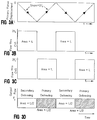
- a flow of L/cycle is maintained in accordance to Figure 3(a)-3(d).
- Eqn 1 and Eqn 2 do not correctly set forth the volumetric flow rate and mass flow rate of a reciprocating pump. Furthermore, the compressibility of the fluid is a function of both pressure and temperature. Liquid chromatography and supercritical fluid chromatography systems typically treat these compressibility factors as constants, however, they vary considerably.
- a method and apparatus for significantly improving the performance of a reciprocating pump by delivering the pumping fluid at a desired pressure and flow rate with minimal flow fluctuations.
- the method includes the step of sensing various pump parameters and adjusting the pumping speed to accommodate for the compressibility of the pumping fluid, the adiabatic heating of the pumping fluid during compression, variations in pumping fluid density, leaks in the check valves or cylinder/piston seals and the primary and secondary switching losses in the fluid flow occurring when the piston reverses direction.
- the compressibility of the pumping fluid directly effects volumetric flow rate and mass flow rate. These effects are much more noticeable when using supercritical fluids such as CO2 than in other liquids.
- the object of the invention is to significantly reduce pumping and flow noise in reciprocating pumps by taking into account the pressure and temperature dependency of the compressibility of the pumping fluid.
- the compression stroke of the pumping cycle is not isothermal as the rapid compression of the fluid causes a significant increase in fluid temperature.
- the density and the mass flow rate also vary with fluid temperature. This results in a positive flow pulse passing to the outlet and results in a flow ripple.
- the pumping fluid in the primary cylinder which is normally compressed to a volume C, is compressed to a different volume C'.
- the value of volume C' is larger than volume C and is calculated so that the fluid reaches the system pressure at the increased temperature and at a constant mass flow rate. Accordingly, it is another object of the invention to decrease the flow variations by taking into account the cyclic increase in temperature caused by the fluid compression.
- Another object of the invention is to compensate for such leaks by measuring the flow with a high pressure flowmeter and increasing the pump speed of either the primary or the secondary piston or both pistons till the expected flow rate is achieved.
- a secondary ripple in the fluid flow occurs when the piston reverses direction at the top of the stroke as some fluid escapes through the secondary check valve to the primary piston (secondary valve switching loss). It is another object of the invention to compensate for this secondary ripple by injecting a small volume of liquid in addition to the steady flow amount.
- the calculated value C'(new volume) is found to be larger from the measured empirical value due to the primary valve switching loss.
- the invention corrects the problem by continuously monitoring the pressure and adjusting the C' value to maintain a minimum pressure ripple. The difference between the calculated C' and the optimum measured C' establishes the switching loss in the primary valve.
- the fluid density in the primary cylinder increases as the fluid cools down to the temperature of the pump wall. This causes the mass flow and pressure to vary during the pumping cycle. Therefore, another objective of the invention is to modulate the pump speed so as to achieve constant mass flow rate and constant pressure.
- a fluid pump as described in U.S. Patent No. 4,883,409 is modified to provide for sensing various pump parameters and adjusting of the pumping speed, such that fluctuations in the pumping pressure and mass flow rate are reduced.
- Figure 4(a) illustrates the addition of mass flow sensors, pump head temperature sensors, inlet and outlet pressure sensors, all of which provide feedback to an electronic pump speed controller.
- the pump drive motor rotation angle, and the corresponding stroke of the two pistons (10,20) is controlled by firmware running on a microprocessor to accomodate for the compressibility of the pumping fluid, the adiabatic heating of the pumping fluid during compression, variations in pumping fluid density, leaks in the check valves or cylinder/piston seals and the primary and secondary switching losses in the fluid flow occurring when the piston reverses direction.
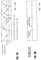
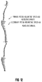
- Figures 5 illustrates the flow patterns for compressible fluids as a function of primary piston displacement, flow through CV2 and the volumetric output flow F v .
- the primary piston moves upward to a calculable position C before the pressure in the primary cylinder increases from the initial intake pressure P i to the outlet pressure P o .
- a negative flow from the outlet, which is ideally maintained at a constant pressure, to the pump will occur during the compression displacement.
- the reduced average volumetric flow rate at an uncompensated outlet pressure F v equals C x f.
- the pump motor is instructed to quickly compress the fluid upon intake by moving the primary piston twice the displacement needed to reach the outlet pressure using the maximum speed possible.
- the flow rate is returned to that of the incompressible fluid, where:
- Both l i and l o can be obtained from the equations of state of the specific fluid employed.
- the pumping fluid heats up and attempts to expand such that the outlet pressure is reached prior to the piston moving to the volume C.
- This effect causes a fast positive flow pulse to pass to the pump outlet (Figure 8b).
- the mass flow rate will be less than the calculated value due to decreased fluid density.
- the mass flow rate will continue to increase according to the time constant of heat exchange between the fluid and pump body.
- the resulting flow waveform due to this phenomena is shown in Figure 8B.
- This effect is more dramatic in fluids having high compressibility such as supercritical compressed gases. For supercritical carbon dioxide at outlet pressures above 200 bar, temperature rise of more than ten degrees centigrade have been calculated and empirically validated.
- the fluid in the primary cylinder is compressed to a different volume C'.
- the value of C' is larger than C and is calculated so that the fluid reaches system pressure at an increased temperature.
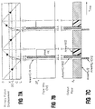
- the primary piston is moved farther by the same displacement (to volume 2C' - L) in order to fill the vacuum created in the secondary cylinder Figure 9A.
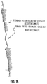
- this will result in the flow waveform shown in Figure 9(b) and the actual plot of Figure 10.
- the pump speed is also programmed to ensure constant mass flow by accounting for the lost flow due to decreased density, and the elimination of flow ripple due to varying density.
- the post-compression temperature is first expressed as a function of time such that the fluid density can be represented as a function of time. From this equation, the piston speed required for constant mass flow can be derived.
- the rate of density variation can be determined using the time function f(t) of heat exchange between the fluid in the pump and its surroundings.
- T c ' The only unknown in Eqn B is the compression temperature T c '.
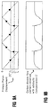
- FIG. 11(a) illustrates the relationship between primary piston displacement, constant volumetric flow rate and constant mass flow rate.
- Figure 11(b) illustrates the flow pattern for carbon dioxide using C' and programming volumetric flow so as to maintain constant mass flow rate.
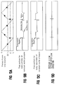
- Absolute flow correction can be made by measuring the flow rate with a high pressure flowmeter and increasing the pump speed till the expected flow rate is achieved. If either side is leaking more than the other, then the flow will be uneven during each associated pump cycle. This leads to flow ripple as illustrated in Figure 13(b) and Figure 13(c). This ripple can be minimized by increasing the speed of the piston on the side which is leaking until a steady flow is obtained ( Figure 13(d). In addition to smoothing out the ripple, this technique also corrects the absolute flow as the actual flow of the more leaky side is increased to that of the less leaky side.
- the differential leak flow ripple can be minimized by pumping fluid into a fixed restrictor whose value is chosen to obtain about the same outlet pressure and the required flow rate.
- Figures 14(b) and 14(c) illustrate the pressure patterns for both a leaky primary and secondary when using a fixed restrictor. The outlet pressure is monitored and analyzed by a microprocessor to indicate which side is leaking the most such that the corresponding piston can be moved faster to correct for the pressure ripple.
- Figure 14(d) illustrates the pressure and flow patterns after leak correction.
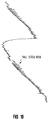
- Figure 15 is the actual plot of Figure 14(d).
- Secondary ripple is a negative ripple due to the flow lost when the pistons change direction as the secondary starts pumping, and is particularly apparent with small flow rates. Injecting an additional volume of liquid during the pumping cycle compensates for this secondary ripple and smooths out the flow rate.
- the injection is performed by setting the pump speed to the maximum speed allowed for a very short time right after the piston changes direction.
- the amount of fluid mass to be injected can be estimated using the area of the negative ripple in the flow diagram.
- a simplified block diagrams illustrating a feedback loop incorporating a pressure and flow transducer are set forth in Figure 4. While examining the output of the mass flow sensor or the pressure transducer, adjustments can be made to the pump drive to minimize the flow ripple.
- the invention also provides for automatically compensating for primary valve switching loss by continuously monitoring the pressure waveform and changing compressibility compensation to maintain the desired pressure. By analyzing the pressure waveform, firmware can detect under-compensation and over-compensation and increase or decrease the amount of compensation accordingly.
- Figure 16 is a flowchart illustrating how the system works, and in particular, the following three general steps required for automatic compensation of primary valve switching loss:
- the control loop includes a system which diverges if neither of the tracking or converging flags are set and there is no compensation reversal (this indicates that the direction of the compensation has changed from the last cycle). In this case, the window is opened up to twice its previous size. Compensation C e is then increased or decreased by the window size if the system was under-compensated or over-compensated respectively.
- the system is determined to be converging on the target if there is compensation reversal and the window size is greater than one. In this case the window gets closed to half its previous size. Compensation C e is increased or decreased by the window size if the system was under-compensated or over-compensated respectively. The converging flag is then set.
- the system is determined to be on track of the target if there is compensation reversal and the window size is set to one. In case of over compensation, the compensation value C e is decreased by on window unit. In case of under compensation, C e is increased by one window unit. Tracking flag is set.
- the tracking flag is set and there was no compensation reversal, the flag is cleared and the window size is left unchanged in order to smoothly control slow target drift while tracking.
- the converging flag is set and there was no compensation reversal, the flag is cleared and the window size is left unchanged in order to converge successfully.
Landscapes
- Engineering & Computer Science (AREA)
- Mechanical Engineering (AREA)
- General Engineering & Computer Science (AREA)
- Computer Hardware Design (AREA)
- Control Of Positive-Displacement Pumps (AREA)
- Reciprocating Pumps (AREA)
Abstract
Description
- The invention relates to a pumping apparatus for delivering liquid at a high pressure, in particular a pumping apparatus for solvent delivery in liquid chromatography or supercritical fluid chromatography. The pumping apparatus pumps a mobile phase and a sample to be separated through the chromatographic system which includes a separation column and various transfer lines.
- In chromatographic analysis, the flow rate of the liquid delivered to the column should be adjustable over a wide range. Once adjusted, it is very important to keep the flow rate constant as fluctuations cause variations in the retention time and associated areas under chromatographic peaks generated by chromatographic detectors of the separated sample. Flow sensitive detectors used in supercritical fluid or liquid chromatography include RI detectors, dielectric constant detectors, electrical conductivity detectors, NPD, ECD and fluorescence detectors. Since the area under the peaks are representative of the concentration of the chromatographically separated sample substances, fluctuations in the flow rate would impair the accuracy and the reproducibility of quantitative measurements. Additionally, many detectors are sensitive to flow and/or pressure ripples.
- The compressibility of chromatographic solvents becomes noticeable at the high pressures encountered in high performance liquid chromatography and supercritical fluid chromatography. Such compressibility results in an additional source of fluctuations in the flow rate as the piston must compress the liquid to its final delivery pressure before actual delivery of liquid starts. This results in the outflow having pulsations which occur at the frequency of the pump. The percent magnitude of pulsations remains substantially constant over a wide range of flow rates, however, as the amplitudes of the peaks in the chromatogram become smaller at low flow rates, the influence of pulsations on the chromatographic results is more pronounced.
- It is known to use a dual piston pump having two interconnected pump heads each with a reciprocating piston. The pistons may be driven via cams and a cam-shaft, a ball-screw drive or any other suitable mechanism which permits a phase difference resulting in a comparatively smooth outflow. A dual piston pump driven via cams and a common cam shaft is known from U.S. Pat. No. 4,352,636. One type of reciprocating pump which incorporates the ball-screw drive is disclosed in U.S. Patent No. 4,883,409 entitled "Pumping Apparatus for Delivering Liquid at High Pressure", and is hereby incorporated by reference. As set forth in Figure 1 the '409 patent discloses a pumping apparatus having two gear driven pistons which reciprocate in opposite directions in two pump chambers, respectively. The pistons are coupled to ball-screw drives which translate the rotary motion of the spindles into a linear motion of the pistons. The stroke volume can be changed by changing the amount in which the spindles are rotated during a pump cycle. Furthermore, a ball-screw drive permits the selection of any desired piston displacement over time during a pump cycle. For example, the displacement may be varied linearly as a function of time or accelerated for a short time to obtain a pre-compression phase.
- Figure 2(a) illustrates the beginning of the intake cycle for a known ball-screw, dual chamber reciprocating pump illustrated in Figure 1 in which the output of the primary pump chamber is connected via a valve to the input of the secondary pump chamber. The stroke of each piston can be varied by controlling the angle of rotation of a reversible drive motor. The gear ratio is chosen to allow the primary piston to sweep twice as much volume as the secondary piston. If the primary and secondary cylinders have the same diameter, then the primary piston must move twice as fast as the secondary piston. Thus, if the primary piston has a volumetric stroke of L, the secondary piston will have a volumetric stroke of L/2. The outlet pressure can be kept constant at Po using a back pressure regulator or a flow restrictor.
- The pumping cycle for this pump is set forth in Figure 2(b). As the primary piston moves downward, the primary pressure decreases causing
check valve 10 to open and checkvalve 20 to close, thus sucking in a fluid volume equal to L from the inlet. At the same time, the secondary piston delivers a volume of liquid (L/2) to the outlet. The pump motor then changes direction and the primary piston moves upward delivering a volume L. One half of this volume (L/2) is delivered to the outlet, and the other half is used to fill the vacuum generated in the secondary cylinder due to its downward motion. Assuming the fluid is incompressible, a flow of L/cycle is maintained in accordance to Figure 3(a)-3(d). The volumetric flow rate Fv for incompressible fluids can be expressed as follows:

Where: - Fv =
- Volumetric flow rate at a defined outlet pressure
- fi =
- Pump frequency in cycles per unit time required to maintain flow rate of Fv when pumping incompressible fluids.
- L =
- Primary piston stroke volume
- ℓo =
- Fluid density at the outlet pressure. Assumed constant for incompressible fluids at all pressures and temperatures.
- Since real fluids are compressible,
Eqn 1 andEqn 2 do not correctly set forth the volumetric flow rate and mass flow rate of a reciprocating pump. Furthermore, the compressibility of the fluid is a function of both pressure and temperature. Liquid chromatography and supercritical fluid chromatography systems typically treat these compressibility factors as constants, however, they vary considerably. - In accordance with this invention, a method and apparatus are described for significantly improving the performance of a reciprocating pump by delivering the pumping fluid at a desired pressure and flow rate with minimal flow fluctuations. The method includes the step of sensing various pump parameters and adjusting the pumping speed to accommodate for the compressibility of the pumping fluid, the adiabatic heating of the pumping fluid during compression, variations in pumping fluid density, leaks in the check valves or cylinder/piston seals and the primary and secondary switching losses in the fluid flow occurring when the piston reverses direction. The compressibility of the pumping fluid directly effects volumetric flow rate and mass flow rate. These effects are much more noticeable when using supercritical fluids such as CO₂ than in other liquids. The assumption of a constant compressibility leads to optimal minimization of fluid fluctuation at only one point of the pressure/temperature characteristic. At other pressures and temperatures, flow fluctuations due to overcompensation or under-compensation becomes apparent. Accordingly, the object of the invention is to significantly reduce pumping and flow noise in reciprocating pumps by taking into account the pressure and temperature dependency of the compressibility of the pumping fluid.
- The compression stroke of the pumping cycle is not isothermal as the rapid compression of the fluid causes a significant increase in fluid temperature. The density and the mass flow rate also vary with fluid temperature. This results in a positive flow pulse passing to the outlet and results in a flow ripple. To eliminate flow variations caused by temperature variations, the pumping fluid in the primary cylinder which is normally compressed to a volume C, is compressed to a different volume C'. The value of volume C' is larger than volume C and is calculated so that the fluid reaches the system pressure at the increased temperature and at a constant mass flow rate. Accordingly, it is another object of the invention to decrease the flow variations by taking into account the cyclic increase in temperature caused by the fluid compression.
- The use of very low pumping flow rates is becoming more popular in liquid chromatography. When using a reciprocating pump at very small flow rates, leaks may form at the check valves or cylinder/piston seals. Identifying these leaks and compensating for them is extremely important when pumping supercritical fluid modifiers as it directly affects the mixing of the modifier in the CO2. Therefore, another object of the invention is to compensate for such leaks by measuring the flow with a high pressure flowmeter and increasing the pump speed of either the primary or the secondary piston or both pistons till the expected flow rate is achieved.
- A secondary ripple in the fluid flow occurs when the piston reverses direction at the top of the stroke as some fluid escapes through the secondary check valve to the primary piston (secondary valve switching loss). It is another object of the invention to compensate for this secondary ripple by injecting a small volume of liquid in addition to the steady flow amount. The calculated value C'(new volume) is found to be larger from the measured empirical value due to the primary valve switching loss. The invention corrects the problem by continuously monitoring the pressure and adjusting the C' value to maintain a minimum pressure ripple. The difference between the calculated C' and the optimum measured C' establishes the switching loss in the primary valve. After the compression stroke, the fluid density in the primary cylinder increases as the fluid cools down to the temperature of the pump wall. This causes the mass flow and pressure to vary during the pumping cycle. Therefore, another objective of the invention is to modulate the pump speed so as to achieve constant mass flow rate and constant pressure.
- The present invention may be better understood, and its numerous objects and advantages will become apparent to those skilled in the art by reference to the accompanying drawings of which:
- Figure 1 is a diagram of the Prior Art pumping apparatus. Figure 2(a) and Figure 2(b) are diagrams illustrating the primary and secondary piston positions during the pumping cycle.
- Figure 3(a), 3(b), 3(c) and 3(d) are fluid displacement and flow patterns through the pump for ideally incompressible fluids.
- Figure 4(a) and 4(b) are block diagrams of the invention is which different levels of sensing devices are employed for generating feedback signals.
- Figure 5(a), 5(b) and 5(c) are fluid displacement and flow patterns of a compressible fluid.
- Figure 6(a), 6(b) and 6(c) illustrates the flow pattern for compressible fluids in which compensation for compressibility is employed.
- Figure 7(a), 7(b) and 7(c) illustrate the flow pattern for compressible fluids in which compensation for compressibility is employed but with finite pump motor speed.
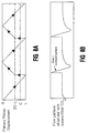
- Figure 8(a) and 8(b) represent the primary piston displacement and corresponding flow pattern observed with supercritical CO₂ with compression value calculated assuming isothermal compression. This is the actual output of a prior art pump which illustrates fluctuations in fluid flow.
- Figure 9(a) and 9(b) represent the primary piston displacement and corresponding flow pattern observed with supercritical CO₂ with adiabatic compensation C' and constant volumetric flow rate.
- Figure 10 is an actual pump output of Figure 9(b) showing flow fluctuations and ball screw noise.
- Figure 11(a) illustrates the relationship between primary piston displacement, constant volumetric flow rate and constant mass flow.
- Figure 11(b) illustrates the pressure and flow pattern for carbon dioxide using adiabatic compensation C' and programming volumetric flow so as to maintain a constant mass flow rate.
- Figure 12 is the actual pump output of Figure 11(b).
- Figure 13(a), 13(b), 13(c) and 13(d) illustrate very low flow patterns for the pump with an unbalanced at a constant outlet pressure and the pressure and flow pattern after leak correction.
- Figure 14(a), 14(b), 14(c) and 14(d) illustrate the pressure patterns for both a leaky primary and secondary when using a fixed restrictor and after leak correction.
- Figure 15 is the actual pump output of Figure 14(d).
- Figure 16 is a flow chart of the compression tracking algorithm.
- In the preferred embodiment, a fluid pump as described in U.S. Patent No. 4,883,409 is modified to provide for sensing various pump parameters and adjusting of the pumping speed, such that fluctuations in the pumping pressure and mass flow rate are reduced.
- In particular, Figure 4(a) illustrates the addition of mass flow sensors, pump head temperature sensors, inlet and outlet pressure sensors, all of which provide feedback to an electronic pump speed controller. The pump drive motor rotation angle, and the corresponding stroke of the two pistons (10,20), is controlled by firmware running on a microprocessor to accomodate for the compressibility of the pumping fluid, the adiabatic heating of the pumping fluid during compression, variations in pumping fluid density, leaks in the check valves or cylinder/piston seals and the primary and secondary switching losses in the fluid flow occurring when the piston reverses direction.
- Figures 5 illustrates the flow patterns for compressible fluids as a function of primary piston displacement, flow through CV2 and the volumetric output flow Fv. In the primary delivery stroke, the primary piston moves upward to a calculable position C before the pressure in the primary cylinder increases from the initial intake pressure Pi to the outlet pressure Po. A negative flow from the outlet, which is ideally maintained at a constant pressure, to the pump will occur during the compression displacement. The reduced average volumetric flow rate at an uncompensated outlet pressure Fv equals C x f. In order to compensate for reduced and discontinuous flow, the pump motor is instructed to quickly compress the fluid upon intake by moving the primary piston twice the displacement needed to reach the outlet pressure using the maximum speed possible. As set forth in Figure 6, the primary piston will quickly move from position L to a new position defined as:

Figure 6 (c) shows the resulting flow patterns. The pump frequency has been increased by a factor of L/C to make up for the reduced flow and is defined as:

- By compensating for the fluid compressibility, the flow rate is returned to that of the incompressible fluid, where:

- In an ideal pump, the temperature of the pumping fluid can be assumed to stay constant when the primary piston moves from position L to position C. Additionally, the mass of the fluid in the primary cylinder stays constant such that:

Or:
Where: - D =
- Primary piston dead volume
- L =
- Primary volumetric stroke
- C =
- The primary piston position at which the primary cylinder pressure has just reached the outlet pressure Po (unknown)
- ℓi =
- Fluid density right after the intake stroke (density at inlet pressure)
- ℓo =
- Fluid density right after the compression stroke (density at outlet pressure)
- Both ℓi and ℓo can be obtained from the equations of state of the specific fluid employed. When compressed, the pumping fluid heats up and attempts to expand such that the outlet pressure is reached prior to the piston moving to the volume C. This effect causes a fast positive flow pulse to pass to the pump outlet (Figure 8b). Right after the compression stroke, the mass flow rate will be less than the calculated value due to decreased fluid density. The mass flow rate will continue to increase according to the time constant of heat exchange between the fluid and pump body. The resulting flow waveform due to this phenomena is shown in Figure 8B. This effect is more dramatic in fluids having high compressibility such as supercritical compressed gases. For supercritical carbon dioxide at outlet pressures above 200 bar, temperature rise of more than ten degrees centigrade have been calculated and empirically validated.
- In order to overcome and virtually eliminate this large flow ripple, the fluid in the primary cylinder is compressed to a different volume C'. The value of C' is larger than C and is calculated so that the fluid reaches system pressure at an increased temperature. The primary piston is moved farther by the same displacement (to
volume 2C' - L) in order to fill the vacuum created in the secondary cylinder Figure 9A. For carbon dioxide with adiabatic compensation, this will result in the flow waveform shown in Figure 9(b) and the actual plot of Figure 10. - The pump speed is also programmed to ensure constant mass flow by accounting for the lost flow due to decreased density, and the elimination of flow ripple due to varying density. In particular, the post-compression temperature is first expressed as a function of time such that the fluid density can be represented as a function of time. From this equation, the piston speed required for constant mass flow can be derived.
- Since the rapid compression of the pumping fluid causes the fluid to heat up and expand, the density decreases. When heat is transferred to the pump body, the pumped fluid cools and the density increases. The rate of density variation can be determined using the time function f(t) of heat exchange between the fluid in the pump and its surroundings.
- For constant mass flow rate:

P(t) can be approximated by the following function:

- ℓi
- initial fluid density right after the fast compression stroke
- ℓf
- final density at steady state pump temperature and outlet pressure
- t
- time
- ℓ (t)
- fluid density as function of time
- V(t)
- pump volume filled with fluid at outlet pressure
- τ
- thermal time constant of heat exchange between the fluid and the pump walls. ∼ 3 seconds
- f
- required mass flow rate
- Therefore a constant entropy curve can be expressed as:


- Thus, we can write:

- The only unknown in Eqn B is the compression temperature Tc'. After solving for Tc', one can substitute Tc' in the fluid equation of State:

and find the new density at this point C' (Pc'). Density and entropy look-up tables for the specific fluid can be used as well as the equations of state for this fluid. Using a "universal" equation of state may be preferable as it can apply to many different fluids and can simplify computer mathematical manipulations. - The value of C' can be found from the equation:

Figure 11(a) illustrates the relationship between primary piston displacement, constant volumetric flow rate and constant mass flow rate. Figure 11(b) illustrates the flow pattern for carbon dioxide using C' and programming volumetric flow so as to maintain constant mass flow rate. - At very low flow rates, leaks may form through check valves or cylinder/piston seals. Absolute flow correction can be made by measuring the flow rate with a high pressure flowmeter and increasing the pump speed till the expected flow rate is achieved. If either side is leaking more than the other, then the flow will be uneven during each associated pump cycle. This leads to flow ripple as illustrated in Figure 13(b) and Figure 13(c). This ripple can be minimized by increasing the speed of the piston on the side which is leaking until a steady flow is obtained (Figure 13(d). In addition to smoothing out the ripple, this technique also corrects the absolute flow as the actual flow of the more leaky side is increased to that of the less leaky side.
- In another embodiment which does not use a high pressure flowmeter, the differential leak flow ripple can be minimized by pumping fluid into a fixed restrictor whose value is chosen to obtain about the same outlet pressure and the required flow rate. Figures 14(b) and 14(c) illustrate the pressure patterns for both a leaky primary and secondary when using a fixed restrictor. The outlet pressure is monitored and analyzed by a microprocessor to indicate which side is leaking the most such that the corresponding piston can be moved faster to correct for the pressure ripple. Figure 14(d) illustrates the pressure and flow patterns after leak correction. Figure 15 is the actual plot of Figure 14(d).
- Secondary ripple is a negative ripple due to the flow lost when the pistons change direction as the secondary starts pumping, and is particularly apparent with small flow rates. Injecting an additional volume of liquid during the pumping cycle compensates for this secondary ripple and smooths out the flow rate. The injection is performed by setting the pump speed to the maximum speed allowed for a very short time right after the piston changes direction. The amount of fluid mass to be injected can be estimated using the area of the negative ripple in the flow diagram. A simplified block diagrams illustrating a feedback loop incorporating a pressure and flow transducer are set forth in Figure 4. While examining the output of the mass flow sensor or the pressure transducer, adjustments can be made to the pump drive to minimize the flow ripple.
- The invention also provides for automatically compensating for primary valve switching loss by continuously monitoring the pressure waveform and changing compressibility compensation to maintain the desired pressure. By analyzing the pressure waveform, firmware can detect under-compensation and over-compensation and increase or decrease the amount of compensation accordingly. Figure 16 is a flowchart illustrating how the system works, and in particular, the following three general steps required for automatic compensation of primary valve switching loss:
- 1) Initially, the empirical compensation Ce is set to equal the theoretically calculated value C'.
- 2) A volumetric "window unit" is entered, for example, 0.1 micro-liter.
- 3) A control loop is entered and repeats itself every cycle starting after the compression stroke.
- The control loop includes a system which diverges if neither of the tracking or converging flags are set and there is no compensation reversal (this indicates that the direction of the compensation has changed from the last cycle). In this case, the window is opened up to twice its previous size. Compensation Ce is then increased or decreased by the window size if the system was under-compensated or over-compensated respectively.
- The system is determined to be converging on the target if there is compensation reversal and the window size is greater than one. In this case the window gets closed to half its previous size. Compensation Ce is increased or decreased by the window size if the system was under-compensated or over-compensated respectively. The converging flag is then set.
- The system is determined to be on track of the target if there is compensation reversal and the window size is set to one. In case of over compensation, the compensation value Ce is decreased by on window unit. In case of under compensation, Ce is increased by one window unit. Tracking flag is set.
- If the tracking flag is set and there was no compensation reversal, the flag is cleared and the window size is left unchanged in order to smoothly control slow target drift while tracking.
- If the converging flag is set and there was no compensation reversal, the flag is cleared and the window size is left unchanged in order to converge successfully.
- Although the best results are obtained by the forgoing pumping method and apparatus, changes and modification of the invention, as set forth in the specifically described embodiments, can be carried out without departing form the scope of the invention which is intended to be limited only by the scope of the appended claims.
(Mass per unit Eqn (2) time)
Where:
which is the volumetric flow rate (piston speed)
For any fluid, entropy "s" is a function of pressure and temperature. This can be expressed as:
Claims (12)
- A multiple cylinder reciprocating pumping apparatus for delivering a liquid or supercritical fluid at a desired pressure and flow rate with minimal fluctuations, comprising:
a first and a second pumping chamber, each having an inlet valve and an exit valve, wherein fluid to be pumped by the pumping apparatus is introduced into the inlet valve of said first pumping chamber and wherein fluid pumped by said pumping apparatus is expelled from the exit valve of said second pumping chamber; and wherein said first and second pumping chambers are coupled to each other through said first exit valve and said second inlet valve; and wherein, said first pumping chamber has a greater pumping capacity than said second pumping chamber; and
a first and second piston which reciprocate out of phase in said respective first and second pumping chambers; wherein said fluid is drawn into said first pumping chamber when said first piston is lowered, closing said check valve between said first and second chamber, while said second pumping chamber is expelling pumping fluid, and wherein said fluid both fills said second chamber and is expelled from said second chamber through said exit valve, when said first piston is raised and the second piston is lowered, as the first chamber has a greater pumping capacity than said second chamber; and
drive means for actuating said pistons; and
sensing means coupled to said pumping chamber to generate a temperature signal and a pressure signal corresponding to the temperature and pressure of the pumping fluid; and
a controller for generating drive signals responsive to said temperature and pressure signals and coupled to said drive means for controlling the speed and position of said first and second pistons to minimize pulsations in the fluid flow exiting the pumping apparatus, wherein, at the beginning of the pumping cycle, said drive means is instructed to rapidly compress the pumping fluid to the desired pressure and flow rate while compensating for the compressibility of the pumping fluid. - The pumping apparatus as claimed in claim 1, wherein said controller generates drive signals to compensate for the decrease in density of the pumping fluid caused by increased temperature upon compression.
- The pumping apparatus as claimed in claim 1, wherein said sensing means generates a fluid leak signal in response to fluid leaks at the check valves or cylinder/piston seals, wherein, said controller generates drive signals in response to said fluid leak signal, for increasing the pumping speed to maintain the desired flow rate and pressure.
- A multiple cylinder pumping apparatus for delivering a liquid or supercritical fluid at a desired pumping pressure and flow rate with minimal fluctuations, comprising:
a plurality of cylinders and associated pistons;
drive means coupled to said pistons for actuating said pistons in accordance to said control signals
sensing means for sensing pump parameters and generating feedback signals corresponding to said sensed parameters;
a controller coupled to said sensing means and said drive means for generating drive signals in response to said feedback signals to control the actuation of said pistons, wherein, said pumping apparatus delivers said liquid or supercritical fluid at a desired pumping pressure and flow rate by adjusting the actuation of said pistons to compensate for said sensed parameters. - The apparatus of claim 4, wherein said sensed pump parameter is the temperature of the fluid within said cylinder and is employed for calculating the density of said fluid such that the pump delivers the pumping fluid at a constant mass flow rate.
- The apparatus of claim 5, wherein said temperature is periodically sensed such that said controller can periodically generate drive signals to compensate for variations in fluid density.
- The apparatus of claim 4, wherein said sensed pump parameter is the pressure of the fluid at the output of the pump, and pressure measurements which are lower than expected values a leak in the pump, and wherein, said controller generates drive signals to increase the speed of primary or secondary pistons or both pistons to compensate for said leaks.
- The apparatus of claim 7, wherein variations in fluid flow rate or pressure indicates the presence of secondary valve switching loss, and wherein, said controller generates drive signals in response thereto such that an additional amount of pumping fluid is injected to maintain a minimum pressure ripple.
- The apparatus of claim 8, wherein the primary valve switching loss is compensated for by increasing the compression stroke and the said loss is automatically tracked.
- A method for delivering a pumping fluid, such as a liquid or supercritical fluid, at a desired pressure and mass flow rate with minimal fluctuations, comprising the method steps of:- sensing the temperature and pressure of the pumping fluid during and the pumping cycle; and- adjusting the pumping speed to compensate for density changes in the pumping fluid resulting from said temperature and pressure changes such that the fluid is pumped at a desired pressure and mass flow rate with minimal fluctuations.
- The method of claim 10, further comprising the step of compensating for leaks in the cylinder/piston seals by increasing the pumping speed of the leaking cylinder/piston, said leaks being identified by the method steps of- sensing the output flow or pressure waveform; and- calculating which cylinder/piston is leaking such that the corresponding pumping speed can be increased.
- The method of claim 11, further comprising the step of compensating for and auto-tracking the valves switching losses.
Applications Claiming Priority (2)
| Application Number | Priority Date | Filing Date | Title |
|---|---|---|---|
| US07/570,183 US5108264A (en) | 1990-08-20 | 1990-08-20 | Method and apparatus for real time compensation of fluid compressibility in high pressure reciprocating pumps |
| US570183 | 1990-08-20 |
Publications (2)
| Publication Number | Publication Date |
|---|---|
| EP0471930A1 true EP0471930A1 (en) | 1992-02-26 |
| EP0471930B1 EP0471930B1 (en) | 1994-12-21 |
Family
ID=24278598
Family Applications (1)
| Application Number | Title | Priority Date | Filing Date |
|---|---|---|---|
| EP91109005A Expired - Lifetime EP0471930B1 (en) | 1990-08-20 | 1991-06-02 | Method for real time compensation of fluid compressibility in high pressure reciprocating pumps |
Country Status (4)
| Country | Link |
|---|---|
| US (1) | US5108264A (en) |
| EP (1) | EP0471930B1 (en) |
| JP (1) | JPH04234578A (en) |
| DE (1) | DE69106079D1 (en) |
Cited By (9)
| Publication number | Priority date | Publication date | Assignee | Title |
|---|---|---|---|---|
| DE4209679A1 (en) * | 1992-03-25 | 1993-12-16 | Schwing Gmbh F | Slurry pump |
| WO1999040325A1 (en) * | 1998-02-04 | 1999-08-12 | Dr.Ing. K. Busch Gmbh Druck + Vakuum | Method and device for regulating a delivery quantity |
| EP1236893A1 (en) * | 2001-02-28 | 2002-09-04 | FMSW sprl | Dosing device with continuous fluid flow |
| WO2004001347A3 (en) * | 2002-06-24 | 2004-03-18 | Alois Anton Ehrler | Device for metering a volume flow |
| EP1589336A1 (en) * | 2005-02-04 | 2005-10-26 | Agilent Technologies, Inc. | Leakage checking and calibration of a liquid delivery system |
| WO2006103133A1 (en) * | 2005-03-31 | 2006-10-05 | Agilent Technologies, Inc. | Compensating temperature-induced errors during piston movement |
| EP1724576A3 (en) * | 2003-11-05 | 2007-03-21 | Agilent Technologies, Inc. | Chromatography system with fluid intake management |
| US8535016B2 (en) | 2004-07-13 | 2013-09-17 | Waters Technologies Corporation | High pressure pump control |
| WO2019086671A1 (en) * | 2017-11-06 | 2019-05-09 | Bozic Alexander | System for pumping a compressible liquid |
Families Citing this family (38)
| Publication number | Priority date | Publication date | Assignee | Title |
|---|---|---|---|---|
| US5635070A (en) * | 1990-07-13 | 1997-06-03 | Isco, Inc. | Apparatus and method for supercritical fluid extraction |
| FR2685738B1 (en) * | 1991-12-27 | 1995-12-08 | Inst Francais Du Petrole | METHOD AND DEVICE FOR OPTIMIZING THE PUMPED TRANSFER OF POLYPHASIC EFFLUENTS. |
| JP3491948B2 (en) * | 1993-03-05 | 2004-02-03 | ウォーターズ・インベストメンツ・リミテッド | Solvent pump feeder |
| US5450743A (en) * | 1994-01-10 | 1995-09-19 | Zymark Corporation | Method for providing constant flow in liquid chromatography system |
| US6135724A (en) * | 1998-07-08 | 2000-10-24 | Oilquip, Inc. | Method and apparatus for metering multiple injection pump flow |
| US6561767B2 (en) * | 2001-08-01 | 2003-05-13 | Berger Instruments, Inc. | Converting a pump for use in supercritical fluid chromatography |
| DE10330121A1 (en) * | 2003-07-04 | 2005-02-03 | Continental Aktiengesellschaft | Method for controlling the operation of a compressor |
| WO2005050190A2 (en) * | 2003-11-05 | 2005-06-02 | Agilent Technologies, Inc. | Chromatography system |
| US20050254972A1 (en) * | 2004-05-14 | 2005-11-17 | Baker Rodney W | Bench top pump |
| JP4709629B2 (en) * | 2005-10-19 | 2011-06-22 | 株式会社日立ハイテクノロジーズ | Pump device |
| DE102008006266B4 (en) | 2008-01-25 | 2011-06-09 | Dionex Softron Gmbh | Sampler for liquid chromatography, in particular for high performance liquid chromatography |
| US8215922B2 (en) | 2008-06-24 | 2012-07-10 | Aurora Sfc Systems, Inc. | Compressible fluid pumping system for dynamically compensating compressible fluids over large pressure ranges |
| US9163618B2 (en) | 2008-06-24 | 2015-10-20 | Agilent Technologies, Inc. | Automated conversion between SFC and HPLC |
| CN102112741B (en) | 2008-08-07 | 2016-01-13 | 安捷伦科技有限公司 | Synchronization of supply streams |
| WO2010020435A1 (en) * | 2008-08-22 | 2010-02-25 | Services Petroliers Schlumberger | Universal flash system and apparatus for petroleum reservoir fluids study |
| JP5922329B2 (en) * | 2008-10-07 | 2016-05-24 | 株式会社プラステコ | CO2 supply system |
| EP2244091B8 (en) * | 2009-04-21 | 2016-02-24 | Agilent Technologies, Inc. | Leak detection upstream of a mixing point |
| US8182680B2 (en) * | 2009-04-29 | 2012-05-22 | Agilent Technologies, Inc. | Primary piston correction during transfer |
| WO2010139359A1 (en) | 2009-06-03 | 2010-12-09 | Agilent Technologies, Inc. | Sample injector with metering device balancing pressure differences in an intermediate valve state |
| US8419936B2 (en) * | 2010-03-23 | 2013-04-16 | Agilent Technologies, Inc. | Low noise back pressure regulator for supercritical fluid chromatography |
| US10058835B2 (en) * | 2011-01-19 | 2018-08-28 | Waters Technologies Corporation | Gradient systems and methods |
| DE102011052848B4 (en) * | 2011-08-19 | 2017-02-09 | Dionex Softron Gmbh | Device for controlling a piston pump unit for liquid chromatography |
| DE102012105323B4 (en) * | 2012-06-19 | 2017-03-16 | Dionex Softron Gmbh | Control device for controlling a piston pump unit for liquid chromatography, in particular high performance liquid chromatography |
| JP6060028B2 (en) * | 2013-04-22 | 2017-01-11 | 株式会社神戸製鋼所 | Gas compressor and wear state determination method |
| CN104122338B (en) * | 2013-04-24 | 2015-11-18 | 中国石油化工股份有限公司 | A kind of mensuration CO 2the device and method of the partition factor in profit |
| WO2014204843A1 (en) * | 2013-06-19 | 2014-12-24 | Waters Technologies Corporation | Carbon dioxide liquid phase |
| CN104251202B (en) * | 2013-06-28 | 2017-03-01 | 伊顿公司 | Offset the control system of fluctuation method for implanting and device and pump |
| US20150078917A1 (en) * | 2013-09-19 | 2015-03-19 | General Electric Company | System and method for converterless operation of motor-driven pumps |
| GB2521523A (en) * | 2013-11-13 | 2015-06-24 | Waters Technologies Corp | A method and an apparatus for controlling fluid flowing through a chromatographic system |
| DE202016100451U1 (en) | 2015-06-25 | 2016-02-16 | Dionex Softron Gmbh | Sampler for liquid chromatography, in particular for high performance liquid chromatography |
| CN107784147B (en) * | 2016-08-31 | 2023-04-18 | 北京普源精电科技有限公司 | Method and device for controlling flow rate of main pump and auxiliary pump of high-pressure infusion pump |
| DE102017115242A1 (en) * | 2017-07-07 | 2019-01-10 | Dionex Softron Gmbh | Pump operation method, use of the method in HPLC, pump, pump system and HPLC system |
| US10480547B2 (en) | 2017-11-30 | 2019-11-19 | Umbra Cuscinetti, Incorporated | Electro-mechanical actuation system for a piston-driven fluid pump |
| FR3090756B1 (en) * | 2018-12-19 | 2021-04-09 | Air Liquide | Pumping device, installation and method of supplying liquid hydrogen |
| WO2020250315A1 (en) * | 2019-06-11 | 2020-12-17 | 株式会社島津製作所 | Mobile phase temperature-control device for supercritical fluid apparatus, and supercritical fluid apparatus |
| CN111046580A (en) * | 2019-12-27 | 2020-04-21 | 上海理工大学 | A Weakly Compressible Model of Water for Centrifugal Pumps Based on Tait's Equation |
| CN113049723B (en) * | 2021-03-26 | 2023-03-31 | 浙江福立分析仪器股份有限公司 | Online pressure rapid and accurate compensation method of automatic sample injector |
| GB2626601A (en) * | 2023-01-30 | 2024-07-31 | Agilent Technologies Inc | Analytical device for solvent characterisation |
Citations (5)
| Publication number | Priority date | Publication date | Assignee | Title |
|---|---|---|---|---|
| FR2012512A1 (en) * | 1968-07-08 | 1970-03-20 | Bayer Ag | |
| FR2490742A1 (en) * | 1980-09-23 | 1982-03-26 | Bruker Analytische Messtechnik | MULTICORPS PISTON PUMP WITH CONSTANT FLOW |
| US4566858A (en) * | 1981-10-08 | 1986-01-28 | Nikkiso Co., Ltd. | Pulsation-free volumetric pump |
| EP0264934A2 (en) * | 1986-10-22 | 1988-04-27 | Hitachi, Ltd. | Low pulsation pump device |
| EP0367099A2 (en) * | 1988-11-03 | 1990-05-09 | Bruker Franzen Analytik GmbH | Liquid piston pump for chromatographic analysis appliances |
Family Cites Families (6)
| Publication number | Priority date | Publication date | Assignee | Title |
|---|---|---|---|---|
| US3787882A (en) * | 1972-09-25 | 1974-01-22 | Ibm | Servo control of ink jet pump |
| US4352636A (en) * | 1980-04-14 | 1982-10-05 | Spectra-Physics, Inc. | Dual piston pump |
| US4681513A (en) * | 1985-02-01 | 1987-07-21 | Jeol Ltd. | Two-stage pump assembly |
| US4797207A (en) * | 1986-09-30 | 1989-01-10 | Spectra Physics, Inc. | Apparatus for controlling a pump to account for compressibility of liquids in obtaining steady flow |
| JPS63173866A (en) * | 1987-01-09 | 1988-07-18 | Hitachi Ltd | Pulsationless pump control method |
| DE3785207T2 (en) * | 1987-09-26 | 1993-07-15 | Hewlett Packard Gmbh | PUMP DEVICE FOR DISPENSING LIQUID AT HIGH PRESSURE. |
-
1990
- 1990-08-20 US US07/570,183 patent/US5108264A/en not_active Expired - Lifetime
-
1991
- 1991-06-02 EP EP91109005A patent/EP0471930B1/en not_active Expired - Lifetime
- 1991-06-02 DE DE69106079T patent/DE69106079D1/en not_active Expired - Lifetime
- 1991-08-14 JP JP3228726A patent/JPH04234578A/en active Pending
Patent Citations (5)
| Publication number | Priority date | Publication date | Assignee | Title |
|---|---|---|---|---|
| FR2012512A1 (en) * | 1968-07-08 | 1970-03-20 | Bayer Ag | |
| FR2490742A1 (en) * | 1980-09-23 | 1982-03-26 | Bruker Analytische Messtechnik | MULTICORPS PISTON PUMP WITH CONSTANT FLOW |
| US4566858A (en) * | 1981-10-08 | 1986-01-28 | Nikkiso Co., Ltd. | Pulsation-free volumetric pump |
| EP0264934A2 (en) * | 1986-10-22 | 1988-04-27 | Hitachi, Ltd. | Low pulsation pump device |
| EP0367099A2 (en) * | 1988-11-03 | 1990-05-09 | Bruker Franzen Analytik GmbH | Liquid piston pump for chromatographic analysis appliances |
Cited By (13)
| Publication number | Priority date | Publication date | Assignee | Title |
|---|---|---|---|---|
| DE4209679A1 (en) * | 1992-03-25 | 1993-12-16 | Schwing Gmbh F | Slurry pump |
| WO1999040325A1 (en) * | 1998-02-04 | 1999-08-12 | Dr.Ing. K. Busch Gmbh Druck + Vakuum | Method and device for regulating a delivery quantity |
| EP1236893A1 (en) * | 2001-02-28 | 2002-09-04 | FMSW sprl | Dosing device with continuous fluid flow |
| WO2002070896A1 (en) * | 2001-02-28 | 2002-09-12 | Cofido S.A. | Continuous-flow fluid dosing device |
| US7263900B2 (en) | 2002-06-24 | 2007-09-04 | Alois Anton Ehrler | Volumetric flow metering device |
| WO2004001347A3 (en) * | 2002-06-24 | 2004-03-18 | Alois Anton Ehrler | Device for metering a volume flow |
| EP1724576A3 (en) * | 2003-11-05 | 2007-03-21 | Agilent Technologies, Inc. | Chromatography system with fluid intake management |
| US8535016B2 (en) | 2004-07-13 | 2013-09-17 | Waters Technologies Corporation | High pressure pump control |
| US7685866B2 (en) | 2005-02-04 | 2010-03-30 | Agilent Technologies, Inc. | Leakage checking and calibrating of a liquid delivery system |
| EP1589336A1 (en) * | 2005-02-04 | 2005-10-26 | Agilent Technologies, Inc. | Leakage checking and calibration of a liquid delivery system |
| WO2006103133A1 (en) * | 2005-03-31 | 2006-10-05 | Agilent Technologies, Inc. | Compensating temperature-induced errors during piston movement |
| US8297936B2 (en) | 2005-03-31 | 2012-10-30 | Agilent Technologies, Inc. | Compensating temperature-induced errors during piston movement |
| WO2019086671A1 (en) * | 2017-11-06 | 2019-05-09 | Bozic Alexander | System for pumping a compressible liquid |
Also Published As
| Publication number | Publication date |
|---|---|
| JPH04234578A (en) | 1992-08-24 |
| DE69106079D1 (en) | 1995-02-02 |
| US5108264A (en) | 1992-04-28 |
| EP0471930B1 (en) | 1994-12-21 |
Similar Documents
| Publication | Publication Date | Title |
|---|---|---|
| EP0471930B1 (en) | Method for real time compensation of fluid compressibility in high pressure reciprocating pumps | |
| US4913624A (en) | Low pulsation displacement pump | |
| US4137011A (en) | Flow control system for liquid chromatographs | |
| US10876525B2 (en) | Liquid feed device, liquid feed control method for liquid feed device, and liquid feed control program for liquid feed device | |
| US4233156A (en) | Liquid chromatography apparatus | |
| US4919595A (en) | Fluid delivery system with deficit flow compensation | |
| US6561767B2 (en) | Converting a pump for use in supercritical fluid chromatography | |
| US4352636A (en) | Dual piston pump | |
| JP3218231B2 (en) | Pump device | |
| US5450743A (en) | Method for providing constant flow in liquid chromatography system | |
| US8535016B2 (en) | High pressure pump control | |
| US7063785B2 (en) | Pump for liquid chromatography | |
| EP0222123B1 (en) | Apparatus and method for liquid chromatography | |
| US11098702B2 (en) | Liquid delivery device and fluid chromatograph | |
| US11035350B2 (en) | Synchronization of supply flow paths | |
| EP0777887B1 (en) | Bimodal liquid chromatography pump employing artificial intelligence logic feedback control | |
| JP4377761B2 (en) | Liquid chromatograph | |
| US4552513A (en) | Multiple piston pump control | |
| US9459239B2 (en) | Intake monitoring for accurate proportioning | |
| EP2210086A1 (en) | Hplc-system with variable flow rate | |
| CN109212114B (en) | Method of pump operation, use of a method in HPLC, pump system and HPLC system | |
| US20080047611A1 (en) | Fluid pump having low pressure metering and high pressure delivering | |
| US4420393A (en) | Pump for liquid chromatography and a chromatograph including the pump | |
| EP0181437B1 (en) | Process and apparatus for chemical analysis by liquid cromatography | |
| WO2006087037A1 (en) | Fluid pump having high pressure metering and high pressure delivering |
Legal Events
| Date | Code | Title | Description |
|---|---|---|---|
| PUAI | Public reference made under article 153(3) epc to a published international application that has entered the european phase |
Free format text: ORIGINAL CODE: 0009012 |
|
| AK | Designated contracting states |
Kind code of ref document: A1 Designated state(s): DE FR GB |
|
| 17P | Request for examination filed |
Effective date: 19920317 |
|
| 17Q | First examination report despatched |
Effective date: 19930505 |
|
| GRAA | (expected) grant |
Free format text: ORIGINAL CODE: 0009210 |
|
| AK | Designated contracting states |
Kind code of ref document: B1 Designated state(s): DE FR GB |
|
| PG25 | Lapsed in a contracting state [announced via postgrant information from national office to epo] |
Ref country code: FR Effective date: 19941221 |
|
| REF | Corresponds to: |
Ref document number: 69106079 Country of ref document: DE Date of ref document: 19950202 |
|
| PG25 | Lapsed in a contracting state [announced via postgrant information from national office to epo] |
Ref country code: DE Effective date: 19950322 |
|
| EN | Fr: translation not filed | ||
| PLBE | No opposition filed within time limit |
Free format text: ORIGINAL CODE: 0009261 |
|
| STAA | Information on the status of an ep patent application or granted ep patent |
Free format text: STATUS: NO OPPOSITION FILED WITHIN TIME LIMIT |
|
| 26N | No opposition filed | ||
| REG | Reference to a national code |
Ref country code: GB Ref legal event code: 732E |
|
| REG | Reference to a national code |
Ref country code: GB Ref legal event code: IF02 |
|
| PGFP | Annual fee paid to national office [announced via postgrant information from national office to epo] |
Ref country code: GB Payment date: 20070628 Year of fee payment: 17 |
|
| GBPC | Gb: european patent ceased through non-payment of renewal fee |
Effective date: 20080602 |
|
| PG25 | Lapsed in a contracting state [announced via postgrant information from national office to epo] |
Ref country code: GB Free format text: LAPSE BECAUSE OF NON-PAYMENT OF DUE FEES Effective date: 20080602 |