EP0471908B1 - Skateboard - Google Patents
Skateboard Download PDFInfo
- Publication number
- EP0471908B1 EP0471908B1 EP90402326A EP90402326A EP0471908B1 EP 0471908 B1 EP0471908 B1 EP 0471908B1 EP 90402326 A EP90402326 A EP 90402326A EP 90402326 A EP90402326 A EP 90402326A EP 0471908 B1 EP0471908 B1 EP 0471908B1
- Authority
- EP
- European Patent Office
- Prior art keywords
- wheel
- pivot
- footboards
- spacer element
- skateboard
- Prior art date
- Legal status (The legal status is an assumption and is not a legal conclusion. Google has not performed a legal analysis and makes no representation as to the accuracy of the status listed.)
- Expired - Lifetime
Links
- 125000006850 spacer group Chemical group 0.000 claims abstract description 25
- 239000000725 suspension Substances 0.000 claims description 15
- 239000000463 material Substances 0.000 description 3
- 229920001875 Ebonite Polymers 0.000 description 1
- 230000002860 competitive effect Effects 0.000 description 1
- 230000005484 gravity Effects 0.000 description 1
- 239000002184 metal Substances 0.000 description 1
- 238000000034 method Methods 0.000 description 1
- 239000004033 plastic Substances 0.000 description 1
- 239000002990 reinforced plastic Substances 0.000 description 1
- 239000012858 resilient material Substances 0.000 description 1
Images


Classifications
-
- A—HUMAN NECESSITIES
- A63—SPORTS; GAMES; AMUSEMENTS
- A63C—SKATES; SKIS; ROLLER SKATES; DESIGN OR LAYOUT OF COURTS, RINKS OR THE LIKE
- A63C17/00—Roller skates; Skate-boards
- A63C17/01—Skateboards
- A63C17/011—Skateboards with steering mechanisms
- A63C17/013—Skateboards with steering mechanisms with parallelograms, follow up wheels or direct steering action
-
- A—HUMAN NECESSITIES
- A63—SPORTS; GAMES; AMUSEMENTS
- A63C—SKATES; SKIS; ROLLER SKATES; DESIGN OR LAYOUT OF COURTS, RINKS OR THE LIKE
- A63C17/00—Roller skates; Skate-boards
- A63C17/01—Skateboards
-
- A—HUMAN NECESSITIES
- A63—SPORTS; GAMES; AMUSEMENTS
- A63C—SKATES; SKIS; ROLLER SKATES; DESIGN OR LAYOUT OF COURTS, RINKS OR THE LIKE
- A63C17/00—Roller skates; Skate-boards
- A63C17/01—Skateboards
- A63C17/014—Wheel arrangements
- A63C17/015—Wheel arrangements with wheels arranged in two pairs
-
- A—HUMAN NECESSITIES
- A63—SPORTS; GAMES; AMUSEMENTS
- A63C—SKATES; SKIS; ROLLER SKATES; DESIGN OR LAYOUT OF COURTS, RINKS OR THE LIKE
- A63C5/00—Skis or snowboards
- A63C5/16—Devices enabling skis to be used whilst held in a particular configuration with respect to each other, e.g. for training purposes
-
- A—HUMAN NECESSITIES
- A63—SPORTS; GAMES; AMUSEMENTS
- A63C—SKATES; SKIS; ROLLER SKATES; DESIGN OR LAYOUT OF COURTS, RINKS OR THE LIKE
- A63C2203/00—Special features of skates, skis, roller-skates, snowboards and courts
- A63C2203/40—Runner or deck of boards articulated between both feet
-
- A—HUMAN NECESSITIES
- A63—SPORTS; GAMES; AMUSEMENTS
- A63C—SKATES; SKIS; ROLLER SKATES; DESIGN OR LAYOUT OF COURTS, RINKS OR THE LIKE
- A63C2203/00—Special features of skates, skis, roller-skates, snowboards and courts
- A63C2203/52—Direct actuation of steering of roller skate or skateboards, e.g. by a foot plate
Definitions
- Conventional skateboards consist of a substantially rigid board which carries two spaced wheel-sets or trucks which are fixed to its underside with the wheels of the wheel-sets lined on a common track.
- the wheels of each wheel-set, on the more elaborate boards, are very slightly steerable through an offset suspension system with the skater steering the board by shifting his feet on and his body position above the board so that the centre of gravity of his weight may be used to vary the adhesion of the wheels on a common wheel-set with the road surface.
- U.S. Patent Nos. 3,771,811 and 4,202,559 disclose boards in which one of the wheel-sets is fixed to the underside of the board while the other is attached to the underside of a rotatable platform at the other end of the board so that the platform and its wheel-set are steerable as a unit by a foot of the skater.
- the purpose of the steering platforms on both boards is, according to the specifications, to provide a board for children or novices which may easily be foot steered without positional shifting of the skaters body on the board.
- a skateboard according to the invention includes two footboards which lie in a common plane with each footboard including a foot platform and a wheel-set which carries two wheels in axial alignment which are fixed to the underside of the platform characterised in that the footboards are spaced from each other by a spacer element for holding the footboards in their spaced relationship and a pivot arrangement having a pivot axis which is perpendicular to the plane of the foot platforms connecting each footboard to the spacer element to enable both footboards to pivot about their pivot axes relatively to the spacer element thereby providing movement of said wheels which corresponds to the movement of said footboards.
- each wheel-set includes a resilient suspension member which is located in the wheel-set to enable limited resilient pivotal movement of the platform relatively to wheel-set attached to it in a direction transverse to the direction of the axis of rotation of the wheels of the wheel-set.
- each wheel-set includes a wheel body, wheel axles, which are fixed to and project from the opposite sides of the body with the wheels being journalled for rotation on the axles, a first pivot pin which is attached to the wheel body with its axis perpendicular to the plane of the foot platforms, a support arrangement on the wheel body, a second pivot pin pivotally connecting the foot platform to the support arrangement on a pivot axis normal to the wheel axis, with the resilient suspension member being located between the support arrangement and the underside of the foot platform to hold the platform horizontal and a pivot arm on the spacer element which is pivotally engaged with the first pivot pin.
- pivot arrangements on the spacer element each carry a rotatable bearing which rides on horizontal faces of the wheel-set body slots to prevent the pivot arms from binding with the wheel-set bodies during pivotal rotation of the footboards relatively to the support element.
- the skateboard may include foot straps which are attached to the foot platforms.
- skateboard of Figures 1 and 2 is shown in the drawings to consist of two footboards 10 and 12 and a spacer element 14 which is pivotally connected at each of its ends to a footboard to hold the footboards in the spaced relationship shown in the drawings.
- Each of the footboards consists, as is more clearly seen in Figures 3 and 4, of a wheel-set body 16 and a foot platform 18.
- the wheel-set bodies each include two stub axles 20 which are threadedly located in bosses 22 which project from opposite sides of the body, wheels 24 which are made from a fairly hard resilient material and rotatably located on the stub axles 20, an upper support arrangement indicated generally at 26, a sector shaped slot 28 which is more clearly seen in Figures 4 and 5, a first pivot pin 30, a resilient suspension pad 32 and a second pivot pin 34 for pivotally holding the foot platform 18 to the support arrangement 26.
- the suspension pad 32 is made from a hard rubber or suitable plastic and, as shown in Figure 3, includes a rectangular base portion and two upwardly and outwardly directed wings 35. The upper surface of the pad is grooved between the wings to locate the pad on the pivot pin 34 in use.
- the support arrangement 26 includes two upwardly directed gabled lugs 36 which are holed to receive the pivot pin 34 and a rectangular recess, not shown, in which the base of the suspension pad 32 is located in use.
- the spacer element 14 consists of an elongated frame member 37 which carries a pivot arm 38 on each of its ends.
- the frame member is made from any suitably rigid and robust material such as reinforced plastic, alluminium or the like.
- the pivot arms 38 each consist of a pivot lug 40 which carries a suitable bush 42, a roller bearing 44 and a spigot 46 which is a press fit in a bore in the end of the frame member 37.
- a locking pin 48 passes through the spigot 46 and the frame member to hold the pivot arm against rotation and withdrawal from the bore in which it is located.
- the slots 28 in the wheel-set body 16 are each outwardly stepped at 50 to a dimension at which the roller bearing 44 on the pivot arm is a nice fit as shown in Figure 4.
- the pivot arm lugs 40 are located in the slots 28 in the wheel-set bodies, the pivot pins 30 are passed from the underside of the bodies through the bush in the lugs 40 and are locked to the bodies by lock nuts 52 which are located in recesses in the bases of the suspension pad recesses in the support arrangement 26.
- the suspension pad 32 is now located in the recess in the upper surface of the support arrangement 26 and the foot platforms are pressed heavily down on to the wings 35 of the suspension pad resiliently to deform the wings downwardly against the bias of the pad material until holes in lugs 54 on the undersides of the foot platforms are in register with the holes in the support arrangement gable lugs 36.
- the pivot pin 34 is now pressed through the registering holes in the gable lugs 36 and lugs 54 on the foot platform and locked in position by means of circlips as shown in Figure 4.
- the pivot pin is now firmly located in the central groove on the upper surface of the suspension pad firmly to locate the suspension pad in the wheel-set.
- the upward bias of the suspension pad wings 35 on the underside of the foot platform holds the platform horizontal while allowing a limited resilient pivotal movement of the platform about the pivot axis of the pin 34.
- the foot platforms 10 and 12 are rotatable about the axes A of the pivot pins 30 within angular limits imposed on them by vertical edges 51 of the slots 28 in the wheel-set bodies 16.
- the chain lines B illustrate the limit positions of the angle of rotation of the support element relatively to the footboards at which the vertical side edges of the slots 28 come into contact with the sides of the pivot arm lugs 40.
- the wheels 24 are just out of breaking contact with the spacer element 37 as illustrated on the left hand side of Figure 1.
- skateboard of Figure 6 as with the skateboard of the previous embodiment, includes two footboards 10' and 12' and a spacer element 14. In this embodiment of the invention, however, the foot platforms 18 are supported on substantially conventional skateboard wheel-sets 52.
- the spacer element 14 of this embodiment of the invention consists of two metal straps 56 and a spacer 58 which is sandwiched between and fixed to the straps to keep them spaced apart vertically.
- the wheel-sets 52 each consist of separate upper and lower portions 60 and 62 and an annular rubber or like resilient torsion member 64.
- the lower portion 62 of each wheel set includes a ring portion which tightly surrounds the torsion member 64 with a ball and socket arrangement 66 connecting the outer ends of the wheel set components.
- a pivot bolt 68 passes through the spacer straps 56 and the bore of the torsion member 64 to be threadedly anchored in the wheel set portion 60.
- the footboards in this embodiment of the invention, are therefore pivotable relatively to the spacer element on the axes A.
- the lower portion 62 of the wheel-sets enable the foot platforms 18 resiliently to pivot in a direction transverse to the spacer element 14 by the torsion members 64 being able resiliently to deform and so tilt within the rings of the lower portion 62 of the wheel-sets while the tilting motion of the platforms is supported by the ball and socket joints 66 on the outer ends of the wheel-sets.
- the footboards 18 of the skateboards of the invention may conveniently include footstraps which are fixed to the platforms to pass over the upper surfaces of the boards in a direction transversed to the wheel axes.
- the upper surfaces of each of the footboards preferably carries a non-skid surface material 90.
- the skateboard of the invention is primarily intended for use as a dynamically operational vehicle for competitive use.
- the board is steered or turned by the rider of the board standing astride the board with his feet on the foot platforms with his foot direction lying in the direction of the wheel axes of the wheel-sets while the board is in motion and splaying his feet to rotate the boards 10 and 12 about their pivot axes A so that each of the wheel sets follows a common curved track with the centre of the curve being the crossing point of lines in register with the axes of the wheels on each footboard.
- the radius of the curve is determined by the degree of splay of the footboards.
- the high performance skateboards of the invention which include a resilient suspension member may, however, also be turned by the rider holding his feet parallel on the boards 10 and 12 and shifting his weight above the board to tilt the board as is the case with a conventional skateboard with non-steerable wheel-sets.
- the optimum turning method of the board of the invention is, however, a combination of both the turning of the footboards about their vertical pivot axes A and by simultaneous weight shift of the rider over the board to tilt the footboards against the bias of the pads 32.
- the rider leans forwardly or backwardly by as much as 45° towards the inside of the turn with the boards tilted to their maximum extent to resist the centrifical force generated in the turn.
- the footboards are either inwardly or outwardly splayed in dependence on whether he is leaning forwardly or backwardly so that the wheel axes point to the centre of the turning radius.
- the manoeuvreability of the board is obviously much greater than is the case with a conventional skateboard with non-steerable wheel-sets with which the wheel track of the board may only slightly be varied or a board in which only one of the wheel-sets is steerable. With boards with one steerable wheel-set, if wheel skid is ignored, the turning radius will be the meeting point of lines which lie on the axes of the two wheel-sets.
- This meeting point will be brought significantly closer to the board if the fixed wheel-set, if it were capable of rotation, was now rotated in the opposite direction to that of the first steerable wheel-set to bring the meeting point on the wheel axle lines far closer to the board significantly to decrease the turning radius of the board as is the case with the board of the invention.
- Another significant advantage which the board of the invention has over conventional boards with non-steerable wheel-sets or boards which have a single steerable wheel-set is that by pivotal movement of both the footboards and suitable weight distribution the board can be caused to follow a sharp sinusoidal track enabling the board to be propelled at fairly high speed over a flat or even an upwardly inclined surface.
Landscapes
- Artificial Filaments (AREA)
- Motorcycle And Bicycle Frame (AREA)
- Pharmaceuticals Containing Other Organic And Inorganic Compounds (AREA)
Abstract
Description
- Conventional skateboards consist of a substantially rigid board which carries two spaced wheel-sets or trucks which are fixed to its underside with the wheels of the wheel-sets lined on a common track. The wheels of each wheel-set, on the more elaborate boards, are very slightly steerable through an offset suspension system with the skater steering the board by shifting his feet on and his body position above the board so that the centre of gravity of his weight may be used to vary the adhesion of the wheels on a common wheel-set with the road surface.
- U.S. Patent Nos. 3,771,811 and 4,202,559 disclose boards in which one of the wheel-sets is fixed to the underside of the board while the other is attached to the underside of a rotatable platform at the other end of the board so that the platform and its wheel-set are steerable as a unit by a foot of the skater. The purpose of the steering platforms on both boards is, according to the specifications, to provide a board for children or novices which may easily be foot steered without positional shifting of the skaters body on the board.
- In yet a further variation of a known skateboard which is described in U.S. Patent N° 4,076,267 the footboard is transversely split at its centre with the two board halves being connected together by a pivot connection which enables the board halves to pivot relatively to each on an axis which lies in the long direction of the board. This board carries conventional wheel trucks as described above with the transversely pivotable board halves perhaps slightly improving the steering capability referred to in connection with conventional wheel trucks.
- It is the object of this invention to provide a skateboard which is steerable and is highly manoeuverable relatively to conventional boards.
- A skateboard according to the invention includes two footboards which lie in a common plane with each footboard including a foot platform and a wheel-set which carries two wheels in axial alignment which are fixed to the underside of the platform characterised in that the footboards are spaced from each other by a spacer element for holding the footboards in their spaced relationship and a pivot arrangement having a pivot axis which is perpendicular to the plane of the foot platforms connecting each footboard to the spacer element to enable both footboards to pivot about their pivot axes relatively to the spacer element thereby providing movement of said wheels which corresponds to the movement of said footboards.
- Further according to the invention each wheel-set includes a resilient suspension member which is located in the wheel-set to enable limited resilient pivotal movement of the platform relatively to wheel-set attached to it in a direction transverse to the direction of the axis of rotation of the wheels of the wheel-set.
- In one form of the invention each wheel-set includes a wheel body, wheel axles, which are fixed to and project from the opposite sides of the body with the wheels being journalled for rotation on the axles, a first pivot pin which is attached to the wheel body with its axis perpendicular to the plane of the foot platforms, a support arrangement on the wheel body, a second pivot pin pivotally connecting the foot platform to the support arrangement on a pivot axis normal to the wheel axis, with the resilient suspension member being located between the support arrangement and the underside of the foot platform to hold the platform horizontal and a pivot arm on the spacer element which is pivotally engaged with the first pivot pin.
- Still further according to the invention the pivot arrangements on the spacer element each carry a rotatable bearing which rides on horizontal faces of the wheel-set body slots to prevent the pivot arms from binding with the wheel-set bodies during pivotal rotation of the footboards relatively to the support element.
- The skateboard may include foot straps which are attached to the foot platforms.
- The invention is now described by way of example only with reference to the drawings in which :
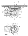
- FIGURE 1 is a partially sectioned plan view of one embodiment of the skateboard of the invention,
- FIGURE 2 is a side elevation fo the Figure 1 board,
- FIGURE 3 is an exploded perspective view as seen from below of one of the footboards of the skateboard of Figures 1 and 2,
- FIGURE 4 is a sectioned side elevation of the assembled footboard of Figure 3.
- FIGURE 5 is a plan view of the Figure 4 footboard shown sectioned on the line 5 - 5 in Figure 4, and
- FIGURE 6 is a side elevation of a second embodiment of the board of the invention.
- The skateboard of Figures 1 and 2 is shown in the drawings to consist of two
footboards spacer element 14 which is pivotally connected at each of its ends to a footboard to hold the footboards in the spaced relationship shown in the drawings. - Each of the footboards consists, as is more clearly seen in Figures 3 and 4, of a wheel-
set body 16 and afoot platform 18. - The wheel-set bodies each include two
stub axles 20 which are threadedly located inbosses 22 which project from opposite sides of the body,wheels 24 which are made from a fairly hard resilient material and rotatably located on thestub axles 20, an upper support arrangement indicated generally at 26, a sector shapedslot 28 which is more clearly seen in Figures 4 and 5, afirst pivot pin 30, aresilient suspension pad 32 and asecond pivot pin 34 for pivotally holding thefoot platform 18 to thesupport arrangement 26. - The
suspension pad 32 is made from a hard rubber or suitable plastic and, as shown in Figure 3, includes a rectangular base portion and two upwardly and outwardly directedwings 35. The upper surface of the pad is grooved between the wings to locate the pad on thepivot pin 34 in use. - The
support arrangement 26 includes two upwardly directedgabled lugs 36 which are holed to receive thepivot pin 34 and a rectangular recess, not shown, in which the base of thesuspension pad 32 is located in use. - The
spacer element 14 consists of anelongated frame member 37 which carries apivot arm 38 on each of its ends. The frame member is made from any suitably rigid and robust material such as reinforced plastic, alluminium or the like. Thepivot arms 38 each consist of apivot lug 40 which carries asuitable bush 42, a roller bearing 44 and aspigot 46 which is a press fit in a bore in the end of theframe member 37. Alocking pin 48 passes through thespigot 46 and the frame member to hold the pivot arm against rotation and withdrawal from the bore in which it is located. - The
slots 28 in the wheel-set body 16 are each outwardly stepped at 50 to a dimension at which the roller bearing 44 on the pivot arm is a nice fit as shown in Figure 4. - To assemble the skateboard the
pivot arm lugs 40 are located in theslots 28 in the wheel-set bodies, thepivot pins 30 are passed from the underside of the bodies through the bush in thelugs 40 and are locked to the bodies bylock nuts 52 which are located in recesses in the bases of the suspension pad recesses in thesupport arrangement 26. - The
suspension pad 32 is now located in the recess in the upper surface of thesupport arrangement 26 and the foot platforms are pressed heavily down on to thewings 35 of the suspension pad resiliently to deform the wings downwardly against the bias of the pad material until holes inlugs 54 on the undersides of the foot platforms are in register with the holes in the supportarrangement gable lugs 36. Thepivot pin 34 is now pressed through the registering holes in thegable lugs 36 andlugs 54 on the foot platform and locked in position by means of circlips as shown in Figure 4. The pivot pin is now firmly located in the central groove on the upper surface of the suspension pad firmly to locate the suspension pad in the wheel-set. The upward bias of thesuspension pad wings 35 on the underside of the foot platform holds the platform horizontal while allowing a limited resilient pivotal movement of the platform about the pivot axis of thepin 34. - From the above it will be appreciated that the
foot platforms pivot pins 30 within angular limits imposed on them byvertical edges 51 of theslots 28 in the wheel-set bodies 16. This is illustrated in Figures 1 and 5 in which the chain lines B illustrate the limit positions of the angle of rotation of the support element relatively to the footboards at which the vertical side edges of theslots 28 come into contact with the sides of thepivot arm lugs 40. At the limit positions of rotation of the footboards thewheels 24 are just out of breaking contact with thespacer element 37 as illustrated on the left hand side of Figure 1. - The skateboard of Figure 6, as with the skateboard of the previous embodiment, includes two footboards 10' and 12' and a
spacer element 14. In this embodiment of the invention, however, thefoot platforms 18 are supported on substantially conventional skateboard wheel-sets 52. - The
spacer element 14 of this embodiment of the invention consists of twometal straps 56 and aspacer 58 which is sandwiched between and fixed to the straps to keep them spaced apart vertically. - The wheel-
sets 52 each consist of separate upper andlower portions resilient torsion member 64. Thelower portion 62 of each wheel set includes a ring portion which tightly surrounds thetorsion member 64 with a ball andsocket arrangement 66 connecting the outer ends of the wheel set components. Apivot bolt 68 passes through thespacer straps 56 and the bore of thetorsion member 64 to be threadedly anchored in the wheel setportion 60. The footboards, in this embodiment of the invention, are therefore pivotable relatively to the spacer element on the axes A. - The
lower portion 62 of the wheel-sets enable thefoot platforms 18 resiliently to pivot in a direction transverse to thespacer element 14 by thetorsion members 64 being able resiliently to deform and so tilt within the rings of thelower portion 62 of the wheel-sets while the tilting motion of the platforms is supported by the ball andsocket joints 66 on the outer ends of the wheel-sets. - The
footboards 18 of the skateboards of the invention may conveniently include footstraps which are fixed to the platforms to pass over the upper surfaces of the boards in a direction transversed to the wheel axes. The upper surfaces of each of the footboards preferably carries a non-skid surface material 90. - The skateboard of the invention is primarily intended for use as a dynamically operational vehicle for competitive use. The board is steered or turned by the rider of the board standing astride the board with his feet on the foot platforms with his foot direction lying in the direction of the wheel axes of the wheel-sets while the board is in motion and splaying his feet to rotate the
boards boards pads 32. In practice in very sharp turns at speed, with the board of the invention the rider leans forwardly or backwardly by as much as 45° towards the inside of the turn with the boards tilted to their maximum extent to resist the centrifical force generated in the turn. His feet and so the footboards are either inwardly or outwardly splayed in dependence on whether he is leaning forwardly or backwardly so that the wheel axes point to the centre of the turning radius. The manoeuvreability of the board is obviously much greater than is the case with a conventional skateboard with non-steerable wheel-sets with which the wheel track of the board may only slightly be varied or a board in which only one of the wheel-sets is steerable. With boards with one steerable wheel-set, if wheel skid is ignored, the turning radius will be the meeting point of lines which lie on the axes of the two wheel-sets. This meeting point will be brought significantly closer to the board if the fixed wheel-set, if it were capable of rotation, was now rotated in the opposite direction to that of the first steerable wheel-set to bring the meeting point on the wheel axle lines far closer to the board significantly to decrease the turning radius of the board as is the case with the board of the invention. - Another significant advantage which the board of the invention has over conventional boards with non-steerable wheel-sets or boards which have a single steerable wheel-set is that by pivotal movement of both the footboards and suitable weight distribution the board can be caused to follow a sharp sinusoidal track enabling the board to be propelled at fairly high speed over a flat or even an upwardly inclined surface.
Claims (7)
- A skateboard including two footboards (10,12;10',12') which lie in a common plane with each footboard (10,12;10',12') including a foot platform (18) and a wheel-set (16,52) which carries two wheels (24) in axial alignment which are fixed to the underside of the platform (18) characterised in that the footboards (10,12;10',12') are spaced from each other by a spacer element (14) for holding the footboards (10,12;10',12') if their spaced relationship and a pivot arrangement (30,40;62,68) having a pivot axis (A) which is perpendicular to the plane of the foot platforms (10,12;10',12') connecting each footboard (10,12;10',12') to the spacer element (14) to enable both footboards (10,12;10',12') to pivot about their pivot axes (A) relatively to the spacer element (14) thereby providing movement of said wheels (24) which corresponds to the movement of said footboards (10,12;10';12').
- A skateboard as claimed in claim 1 characterised in that each wheel-set (16,52) includes a resilient suspension member (32,64) which is located in the wheel set (16,52) to enable limited resilient pivotal movement of the platform (18) relatively to wheel-set (16,52) attached to it in a direction transverse to the direction of the axis of rotation of the wheels (24) of the wheel-set (16,52).
- A skateboard as claimed in claim 2 characterised in that each wheel-set includes a wheel body (16), wheel axles (20), which are fixed to and project from the opposite sides of the body (16) with the wheels (24) being journalled for rotation on the axles (20), a first pivot pin (30) which is attached to the wheel body (16) with its axis (A) perpendicular to the plane of the foot platforms (10,12;10',12'), a support arrangement (26) on the wheel body (16), a second pivot pin (34) pivotally connecting the foot platform (18) to the support arrangement (26) on a pivot axis normal to the wheel axis, with the resilient suspension menber (32) being located between the support arrangement (26) and the underside of the foot platform (18) to hold the platform (18) horizontal and a pivot arm (38) on the spacer element (14) which is pivotally engaged with the first pivot pin (30).
- A skateboard as claimed in claim 3 characterised in that the wheel body (16) and the support arrangement (26) of each wheel set (16) are integral to provide a wheel-set body (16) with the pivot arms (38) on the spacer element being engaged with the first pivot pins (30) of each wheel-set (16) trough slots (28) in the wheel-set bodies (16).
- A skateboard as claimed in claim 4 characterised in that the slots (28) in the wheel set bodies (16) have radially displaced vertical edges (51) to stop rotation of the spacer element (14) pivot arms (38) on the first pivot pins (30) to prevent the wheels (24) from coming into contact with the spacer element (14).
- A skateboard as claimed in claim 4 characterised in that the pivot arms (38) on the spacer element (14) each carry a rotatable bearing (44) which rides on horizontal faces (50) of the wheel set body slots (28) to prevent the pivot arms (38) from binding with the wheel-set bodies (16) during pivotal rotation of the footboards (10,12) relatively to the support element (14).
- A skateboard as claimed in any one of the above claims including foot straps which are attached to the foot platforms (10,12).
Applications Claiming Priority (1)
| Application Number | Priority Date | Filing Date | Title |
|---|---|---|---|
| ZA88576 | 1988-01-28 |
Publications (2)
| Publication Number | Publication Date |
|---|---|
| EP0471908A1 EP0471908A1 (en) | 1992-02-26 |
| EP0471908B1 true EP0471908B1 (en) | 1994-11-02 |
Family
ID=25579155
Family Applications (1)
| Application Number | Title | Priority Date | Filing Date |
|---|---|---|---|
| EP90402326A Expired - Lifetime EP0471908B1 (en) | 1988-01-28 | 1990-08-21 | Skateboard |
Country Status (8)
| Country | Link |
|---|---|
| US (1) | US4955626A (en) |
| EP (1) | EP0471908B1 (en) |
| AT (1) | ATE113492T1 (en) |
| AU (1) | AU626705B2 (en) |
| DE (1) | DE69013910T2 (en) |
| ES (1) | ES2066164T3 (en) |
| GB (1) | GB2246076B (en) |
| ZA (1) | ZA89600B (en) |
Cited By (1)
| Publication number | Priority date | Publication date | Assignee | Title |
|---|---|---|---|---|
| US20130277939A1 (en) * | 2012-04-24 | 2013-10-24 | J.D. Japan Co., Ltd. | Skateboard |
Families Citing this family (93)
| Publication number | Priority date | Publication date | Assignee | Title |
|---|---|---|---|---|
| DE69219463T2 (en) * | 1991-03-01 | 1997-11-13 | Victor Manuel Pracas | SKATEBOARD CHASSIS |
| FR2715319A1 (en) * | 1994-01-24 | 1995-07-28 | Vikar Georges | Roller skate with plate holding pairs of rollers |
| US5540455A (en) * | 1994-02-23 | 1996-07-30 | Chambers; Lile R. | Articulating skateboard with springable connector |
| DE4422119A1 (en) * | 1994-06-24 | 1996-01-04 | Uwe Barthel | Scooter-like vehicle |
| US5458351A (en) * | 1994-12-19 | 1995-10-17 | Yu; Fu B. | Skate board combination |
| DE19515953A1 (en) * | 1995-05-02 | 1996-11-07 | Fu Bin Yu | Ski-board or snow-board combination with two skis |
| US5505474A (en) * | 1995-05-04 | 1996-04-09 | Yeh; Hsiu-Ying | Folding skateboard |
| US5794955A (en) * | 1995-07-27 | 1998-08-18 | Flynn; Raymond G. | Mountain board |
| DE19607544A1 (en) * | 1996-02-28 | 1997-09-04 | Robert Boehm | Muscle-powered mover with standing surface |
| USD397753S (en) | 1996-04-08 | 1998-09-01 | Lin liao yu-ying | Skateboard |
| US5833252A (en) * | 1996-09-20 | 1998-11-10 | Strand; Steen | Lateral sliding roller board |
| US6158752A (en) * | 1998-09-09 | 2000-12-12 | Kay; Albert R. | Wheeled vehicle with control system |
| DE19843483C1 (en) * | 1998-09-22 | 1999-12-09 | Boards Unlimited Sportartikel | Skateboard with pivotal wheel axles |
| GB2346811B (en) * | 1999-02-17 | 2001-01-10 | Joseph Thompson | Drive board |
| US6257614B1 (en) * | 1999-12-14 | 2001-07-10 | John C. Duggan | Dynamic syncronous pivoting boot and foot mounting system for sportingboards |
| US6536788B1 (en) * | 2000-10-30 | 2003-03-25 | Ferenc Kuncz | Skateboard integral interchangeable independent suspension truck-free with aerodynamic board design and rolling devices systems |
| US7083178B2 (en) * | 2001-04-11 | 2006-08-01 | Steven Dickinson Potter | Balancing skateboard |
| US6561530B2 (en) * | 2001-04-27 | 2003-05-13 | Pull-Buoy, Inc. | Gym scooter |
| USD473905S1 (en) | 2002-01-04 | 2003-04-29 | Minson Enterprises Co., Ltd. | Foldable skateboard |
| US20050029757A1 (en) * | 2002-02-01 | 2005-02-10 | Jon Fiebing | Swivelable mount for attaching a binding to a snowboard |
| US20040035616A1 (en) * | 2002-08-21 | 2004-02-26 | Fang-Chun Yu | Scooter |
| US20040035621A1 (en) * | 2002-08-21 | 2004-02-26 | Fang-Chun Yu | Scooter |
| US20040041360A1 (en) * | 2002-08-29 | 2004-03-04 | Lukoszek Benjamin Shane | Truck assemblies for skateboards |
| US20060186617A1 (en) * | 2003-07-11 | 2006-08-24 | Ryan Farrelly | Personal transportation device for supporting a user's foot having multiple transportation attachments |
| WO2005044406A1 (en) * | 2003-11-05 | 2005-05-19 | Gapsoo Lee | Partially revolving wheel assembly |
| WO2006002205A2 (en) | 2004-06-21 | 2006-01-05 | Cole Jeffrey E | Truck assembly for a skateboard, wheeled platform, or vehicle |
| US7232139B2 (en) | 2004-06-21 | 2007-06-19 | Cole Jeffrey E | Truck assembly for a skateboard, wheeled platform, or vehicle |
| CN2714112Y (en) * | 2004-09-13 | 2005-08-03 | 江显灿 | Sliding plate |
| US7237784B1 (en) | 2004-12-01 | 2007-07-03 | Joseph Monteleone | Rotating skateboard |
| US7325819B2 (en) * | 2005-01-25 | 2008-02-05 | No Un Kwak | Skateboard |
| US20060244230A1 (en) * | 2005-01-31 | 2006-11-02 | Dwayne Glowner | Skateboard with rollers |
| GB2440894A (en) * | 2005-05-10 | 2008-02-13 | Seung Youl Lee | Skateboard capable of all-direction running |
| KR100711650B1 (en) * | 2005-05-10 | 2007-04-27 | 이승열 | Skateboard capable of all-direction running |
| WO2006129918A1 (en) * | 2005-06-01 | 2006-12-07 | Hong-Kee Kim | Link type skateboard |
| US7635136B2 (en) | 2005-06-21 | 2009-12-22 | Jeffrey E. Cole | Truck assembly for a skateboard, wheeled platform, or vehicle |
| US8628099B2 (en) * | 2005-08-03 | 2014-01-14 | Portaboard, LLC | Removable wheel mounting assembly |
| US7243931B2 (en) * | 2005-08-03 | 2007-07-17 | Far Great Plastics Industrial Co., Ltd. | Turning device for a wheel set |
| US20070029750A1 (en) * | 2005-08-03 | 2007-02-08 | Gregory Brett J | Disassemblable skateboard for improved portability |
| KR100612427B1 (en) * | 2006-04-12 | 2006-08-16 | 트라이스포츠 주식회사 | Voluntary Advance Board |
| US7766351B2 (en) * | 2006-04-28 | 2010-08-03 | Razor Usa, Llc | One piece flexible skateboard |
| US7338056B2 (en) * | 2006-04-28 | 2008-03-04 | Razor Usa, Llc | One piece flexible skateboard |
| US8414000B2 (en) * | 2006-04-28 | 2013-04-09 | Razor USA, Inc. | One piece flexible skateboard |
| US20070273118A1 (en) * | 2006-05-24 | 2007-11-29 | Amelia Conrad | Inline skateboard |
| US8282114B2 (en) * | 2006-11-30 | 2012-10-09 | Magee Thane G | Skateboard deck |
| US7600768B2 (en) * | 2007-09-05 | 2009-10-13 | Razor Usa, Llc | One piece flexible skateboard |
| US7775534B2 (en) * | 2007-11-28 | 2010-08-17 | Razor USA, Inc. | Flexible skateboard with grinding tube |
| US20090166993A1 (en) * | 2007-12-30 | 2009-07-02 | Flexibility Concepts, Ltd. | Momentum steering system for a vehicle or carriers |
| US20090174163A1 (en) * | 2008-01-08 | 2009-07-09 | Freeline Sports, Inc. | Personal transportation device for supporting a user's foot |
| US8186693B2 (en) | 2008-03-06 | 2012-05-29 | Leverage Design Ltd. | Transportation device with pivoting axle |
| BRPI0911842A2 (en) * | 2008-05-13 | 2015-10-06 | Freeline Sports Inc | personal transport device to support a user's foot |
| US8113524B2 (en) * | 2008-07-09 | 2012-02-14 | Alon Karpman | Hubless personal vehicle |
| US20100092806A1 (en) * | 2008-10-14 | 2010-04-15 | Honeywell International Inc. | Miniature powered antenna for wireless communications and related system and method |
| US8079604B2 (en) * | 2009-05-28 | 2011-12-20 | Surfskate Industries, Llc | Skateboard providing substantial freedom of movement of the front truck assembly |
| IT1394607B1 (en) | 2009-06-08 | 2012-07-05 | Bolditalia S R L | REFINEMENT IN SKIING OR TABLE ON WHEELS. |
| US20120091677A1 (en) * | 2010-10-14 | 2012-04-19 | Wu Chen-Sung | Skateboard |
| US20120104715A1 (en) * | 2010-11-03 | 2012-05-03 | Joseph Michael Alotta | Multi-person skateboard system |
| CN102029057B (en) * | 2011-01-19 | 2012-06-20 | 太仓市车中宝休闲用品有限公司 | Tail-swinging four-wheel skateboard |
| US8500145B2 (en) * | 2011-01-25 | 2013-08-06 | Chin Chen-Huang | Skateboard |
| USD700937S1 (en) | 2011-10-18 | 2014-03-11 | No Snow Ventures Llc | Wheeled riding device |
| US8540284B2 (en) * | 2011-10-18 | 2013-09-24 | No Snow Ventures, LLC | Snowboard simulation riding device |
| CN202987412U (en) | 2012-01-20 | 2013-06-12 | 雷泽美国有限责任公司 | Brake assembly for personal movable vehicle and personal movable vehicle |
| USD693414S1 (en) | 2012-03-15 | 2013-11-12 | Razor Usa Llc | Electric scooter |
| US8925936B1 (en) * | 2013-03-17 | 2015-01-06 | Dave Clos | Skateboard with one or more user maneuverable trucks |
| USD742464S1 (en) | 2013-11-29 | 2015-11-03 | Richard Louis Vitacco | Rider operated flexible body skate plate |
| KR101522471B1 (en) * | 2013-12-12 | 2015-05-22 | 임채흥 | skate board |
| US9409079B2 (en) * | 2014-01-22 | 2016-08-09 | David Park | Dry-land alpine skis |
| EP3223923A1 (en) | 2014-11-26 | 2017-10-04 | Razor USA LLC | Powered wheeled board |
| USD770585S1 (en) | 2015-05-04 | 2016-11-01 | Razor Usa Llc | Skateboard |
| WO2017015249A1 (en) * | 2015-07-21 | 2017-01-26 | Smith Corey C | Steerable wheel assembly employing lean-to-steer mechanism |
| US10071303B2 (en) | 2015-08-26 | 2018-09-11 | Malibu Innovations, LLC | Mobilized cooler device with fork hanger assembly |
| US10807659B2 (en) | 2016-05-27 | 2020-10-20 | Joseph L. Pikulski | Motorized platforms |
| USD810836S1 (en) | 2015-10-29 | 2018-02-20 | Razor Usa Llc | Electric scooter |
| EP3405361B1 (en) | 2016-01-22 | 2023-03-15 | Razor USA LLC | Rear drive assembly and personal mobility vehicle |
| US12403974B2 (en) | 2016-01-22 | 2025-09-02 | Razor Usa Llc | Electric scooter |
| WO2018013994A1 (en) | 2016-07-15 | 2018-01-18 | Razor Usa Llc | Powered mobility systems |
| JP1593302S (en) | 2016-09-02 | 2017-12-18 | ||
| WO2018152355A1 (en) * | 2017-02-15 | 2018-08-23 | Roll, Inc. | Roller board with one or more user-maneuverable trucks and north-seeking return mechanism |
| US10858060B2 (en) * | 2017-02-15 | 2020-12-08 | Roll, Inc. | Roller board with one or more user-maneuverable trucks and north-seeking return mechanism |
| US9987546B1 (en) * | 2017-02-15 | 2018-06-05 | Roll, Inc. | Roller board with one or more user-maneuverable trucks and north-seeking return mechanism |
| US12042716B2 (en) | 2017-04-18 | 2024-07-23 | Razor Usa Llc | Powered wheeled board |
| USD912180S1 (en) | 2017-09-18 | 2021-03-02 | Razor Usa Llc | Personal mobility vehicle |
| EP3810297A4 (en) | 2018-06-01 | 2022-01-19 | Razor USA LLC | PERSONAL MOBILITY VEHICLES WITH DETACHABLE DRIVE SET |
| USD1020912S1 (en) | 2018-06-05 | 2024-04-02 | Razor Usa Llc | Electric scooter |
| US11266901B2 (en) | 2018-10-19 | 2022-03-08 | Mga Entertainment, Inc. | Motorized skateboard with pressure-activated direct reverse steering |
| DE102019001363A1 (en) * | 2019-02-26 | 2020-08-27 | Oleg Lohnes Therapeutikum GmbH | Skateboard mlt steering gear |
| EP3934772B1 (en) | 2019-03-06 | 2026-04-22 | Razor USA LLC | Powered wheeled board |
| JP2022548300A (en) | 2019-09-18 | 2022-11-17 | レイザー・ユーエスエー・エルエルシー | Casterboard with removable inserts |
| WO2022032136A1 (en) | 2020-08-07 | 2022-02-10 | Razor Usa Llc | Electric scooter with removable battery |
| USD1072062S1 (en) | 2020-09-14 | 2025-04-22 | Razor Usa Llc | Electric scooter |
| USD1053956S1 (en) | 2020-09-14 | 2024-12-10 | Razor Usa Llc | Scooter |
| USD1050269S1 (en) | 2020-09-14 | 2024-11-05 | Razor Usa Llc | Scooter |
| CN213347728U (en) | 2020-09-29 | 2021-06-04 | 美国锐哲有限公司 | a skateboard |
| WO2023056340A1 (en) | 2021-09-30 | 2023-04-06 | Razor Usa Llc | Personal mobility vehicles with adjustable wheel positions |
Family Cites Families (10)
| Publication number | Priority date | Publication date | Assignee | Title |
|---|---|---|---|---|
| BE472004A (en) * | ||||
| US2474946A (en) * | 1946-01-19 | 1949-07-05 | Henry M Kinslow | Wheeled vehicle of the scooter type |
| US3771811A (en) * | 1972-08-16 | 1973-11-13 | Campos Bueno A De | Child {40 s coaster |
| US4054297A (en) * | 1976-06-18 | 1977-10-18 | Ermico Enterprises | Weight biased steering mechanism |
| US4076267A (en) * | 1976-09-20 | 1978-02-28 | Willis Leonard Lipscomb | Articulated skateboard |
| US4082306A (en) * | 1976-12-09 | 1978-04-04 | Gregg Sheldon | Torsion bar skateboard |
| US4202559A (en) * | 1978-08-10 | 1980-05-13 | Piazza John Jr | Skateboard |
| US4221394A (en) * | 1978-09-18 | 1980-09-09 | Richard E. Gerardi | Snow vehicle |
| NO163597C (en) * | 1986-12-19 | 1990-06-27 | Stefan Kubierschky | CONTROL DEVICE FOR A ONE OR TWO TRACKED TOOL. |
| US5372383A (en) * | 1988-08-01 | 1994-12-13 | Kubierschky; Stefan | Steerable chassis arrangement for roller skis |
-
1989
- 1989-01-25 US US07/301,494 patent/US4955626A/en not_active Expired - Lifetime
- 1989-01-26 ZA ZA89600A patent/ZA89600B/en unknown
-
1990
- 1990-07-16 GB GB9015560A patent/GB2246076B/en not_active Expired - Fee Related
- 1990-07-23 AU AU59729/90A patent/AU626705B2/en not_active Ceased
- 1990-08-21 DE DE69013910T patent/DE69013910T2/en not_active Expired - Fee Related
- 1990-08-21 AT AT90402326T patent/ATE113492T1/en not_active IP Right Cessation
- 1990-08-21 ES ES90402326T patent/ES2066164T3/en not_active Expired - Lifetime
- 1990-08-21 EP EP90402326A patent/EP0471908B1/en not_active Expired - Lifetime
Cited By (1)
| Publication number | Priority date | Publication date | Assignee | Title |
|---|---|---|---|---|
| US20130277939A1 (en) * | 2012-04-24 | 2013-10-24 | J.D. Japan Co., Ltd. | Skateboard |
Also Published As
| Publication number | Publication date |
|---|---|
| US4955626A (en) | 1990-09-11 |
| ATE113492T1 (en) | 1994-11-15 |
| ZA89600B (en) | 1990-12-28 |
| GB2246076B (en) | 1994-02-02 |
| EP0471908A1 (en) | 1992-02-26 |
| DE69013910T2 (en) | 1995-05-24 |
| ES2066164T3 (en) | 1995-03-01 |
| DE69013910D1 (en) | 1994-12-08 |
| GB2246076A (en) | 1992-01-22 |
| GB9015560D0 (en) | 1990-09-05 |
| AU5972990A (en) | 1992-04-16 |
| AU626705B2 (en) | 1992-08-06 |
Similar Documents
| Publication | Publication Date | Title |
|---|---|---|
| EP0471908B1 (en) | Skateboard | |
| US4054297A (en) | Weight biased steering mechanism | |
| US7083178B2 (en) | Balancing skateboard | |
| US6059303A (en) | In-line skateboard | |
| US5263725A (en) | Skateboard truck assembly | |
| US5826895A (en) | In-line skateboard | |
| US5474314A (en) | Coaster board | |
| US6019382A (en) | Configurable wheel truck for skateboards or roller skates incorporating novel wheel designs | |
| US5975546A (en) | Lateral sliding roller board | |
| US5169166A (en) | Steering mechanism | |
| US4398734A (en) | Truck design for a skate-type device | |
| US5984328A (en) | Two-wheeled skateboard | |
| US4445699A (en) | Coaster and swivel assembly therefor | |
| US4738456A (en) | Wheeled ski simulator | |
| US4159830A (en) | Wheel truck for steerable platform | |
| US20190255422A1 (en) | Laterally-sliding board with bifurcated trucks | |
| US6270096B1 (en) | Steerable in-line skateboard | |
| WO2004020059A1 (en) | Truck assemblies for skateboards | |
| US20040155421A1 (en) | All-terrain board | |
| WO1997004844A1 (en) | Mountain board | |
| US20070114743A1 (en) | Side motion propelled skateboard device | |
| US7000930B2 (en) | Tandem-wheeled riding device | |
| US6343803B1 (en) | Skateboard and related apparatus | |
| US6832765B1 (en) | Steerable in-line skates | |
| KR0160491B1 (en) | Skate board |
Legal Events
| Date | Code | Title | Description |
|---|---|---|---|
| PUAI | Public reference made under article 153(3) epc to a published international application that has entered the european phase |
Free format text: ORIGINAL CODE: 0009012 |
|
| AK | Designated contracting states |
Kind code of ref document: A1 Designated state(s): AT CH DE ES FR GR IT LI NL SE |
|
| 17P | Request for examination filed |
Effective date: 19920805 |
|
| 17Q | First examination report despatched |
Effective date: 19930524 |
|
| GRAA | (expected) grant |
Free format text: ORIGINAL CODE: 0009210 |
|
| AK | Designated contracting states |
Kind code of ref document: B1 Designated state(s): AT CH DE ES FR GR IT LI NL SE |
|
| PG25 | Lapsed in a contracting state [announced via postgrant information from national office to epo] |
Ref country code: GR Free format text: LAPSE BECAUSE OF FAILURE TO SUBMIT A TRANSLATION OF THE DESCRIPTION OR TO PAY THE FEE WITHIN THE PRESCRIBED TIME-LIMIT Effective date: 19941102 |
|
| REF | Corresponds to: |
Ref document number: 113492 Country of ref document: AT Date of ref document: 19941115 Kind code of ref document: T |
|
| REF | Corresponds to: |
Ref document number: 69013910 Country of ref document: DE Date of ref document: 19941208 |
|
| ITF | It: translation for a ep patent filed | ||
| ET | Fr: translation filed | ||
| PG25 | Lapsed in a contracting state [announced via postgrant information from national office to epo] |
Ref country code: SE Effective date: 19950202 |
|
| REG | Reference to a national code |
Ref country code: ES Ref legal event code: FG2A Ref document number: 2066164 Country of ref document: ES Kind code of ref document: T3 |
|
| PLBE | No opposition filed within time limit |
Free format text: ORIGINAL CODE: 0009261 |
|
| STAA | Information on the status of an ep patent application or granted ep patent |
Free format text: STATUS: NO OPPOSITION FILED WITHIN TIME LIMIT |
|
| 26N | No opposition filed | ||
| PGFP | Annual fee paid to national office [announced via postgrant information from national office to epo] |
Ref country code: NL Payment date: 20050823 Year of fee payment: 16 |
|
| PGFP | Annual fee paid to national office [announced via postgrant information from national office to epo] |
Ref country code: AT Payment date: 20050826 Year of fee payment: 16 |
|
| PGFP | Annual fee paid to national office [announced via postgrant information from national office to epo] |
Ref country code: CH Payment date: 20050830 Year of fee payment: 16 |
|
| PG25 | Lapsed in a contracting state [announced via postgrant information from national office to epo] |
Ref country code: AT Free format text: LAPSE BECAUSE OF NON-PAYMENT OF DUE FEES Effective date: 20060821 |
|
| PG25 | Lapsed in a contracting state [announced via postgrant information from national office to epo] |
Ref country code: LI Free format text: LAPSE BECAUSE OF NON-PAYMENT OF DUE FEES Effective date: 20060831 Ref country code: CH Free format text: LAPSE BECAUSE OF NON-PAYMENT OF DUE FEES Effective date: 20060831 |
|
| PGFP | Annual fee paid to national office [announced via postgrant information from national office to epo] |
Ref country code: IT Payment date: 20060831 Year of fee payment: 17 |
|
| PGFP | Annual fee paid to national office [announced via postgrant information from national office to epo] |
Ref country code: DE Payment date: 20061102 Year of fee payment: 17 |
|
| PGFP | Annual fee paid to national office [announced via postgrant information from national office to epo] |
Ref country code: FR Payment date: 20061108 Year of fee payment: 17 |
|
| PGFP | Annual fee paid to national office [announced via postgrant information from national office to epo] |
Ref country code: ES Payment date: 20061114 Year of fee payment: 17 |
|
| PG25 | Lapsed in a contracting state [announced via postgrant information from national office to epo] |
Ref country code: NL Free format text: LAPSE BECAUSE OF NON-PAYMENT OF DUE FEES Effective date: 20070301 |
|
| REG | Reference to a national code |
Ref country code: CH Ref legal event code: PL |
|
| NLV4 | Nl: lapsed or anulled due to non-payment of the annual fee |
Effective date: 20070301 |
|
| REG | Reference to a national code |
Ref country code: FR Ref legal event code: ST Effective date: 20080430 |
|
| PG25 | Lapsed in a contracting state [announced via postgrant information from national office to epo] |
Ref country code: DE Free format text: LAPSE BECAUSE OF NON-PAYMENT OF DUE FEES Effective date: 20080301 |
|
| PG25 | Lapsed in a contracting state [announced via postgrant information from national office to epo] |
Ref country code: FR Free format text: LAPSE BECAUSE OF NON-PAYMENT OF DUE FEES Effective date: 20070831 |
|
| REG | Reference to a national code |
Ref country code: ES Ref legal event code: FD2A Effective date: 20070822 |
|
| PG25 | Lapsed in a contracting state [announced via postgrant information from national office to epo] |
Ref country code: ES Free format text: LAPSE BECAUSE OF NON-PAYMENT OF DUE FEES Effective date: 20070822 |
|
| PG25 | Lapsed in a contracting state [announced via postgrant information from national office to epo] |
Ref country code: IT Free format text: LAPSE BECAUSE OF NON-PAYMENT OF DUE FEES Effective date: 20070821 |