EP0470934B1 - Method of producing a magnetic recording medium - Google Patents
Method of producing a magnetic recording medium Download PDFInfo
- Publication number
- EP0470934B1 EP0470934B1 EP91810611A EP91810611A EP0470934B1 EP 0470934 B1 EP0470934 B1 EP 0470934B1 EP 91810611 A EP91810611 A EP 91810611A EP 91810611 A EP91810611 A EP 91810611A EP 0470934 B1 EP0470934 B1 EP 0470934B1
- Authority
- EP
- European Patent Office
- Prior art keywords
- recording medium
- magnetic recording
- thin film
- ferromagnetic metal
- metal thin
- Prior art date
- Legal status (The legal status is an assumption and is not a legal conclusion. Google has not performed a legal analysis and makes no representation as to the accuracy of the status listed.)
- Expired - Lifetime
Links
Images


Classifications
-
- G—PHYSICS
- G11—INFORMATION STORAGE
- G11B—INFORMATION STORAGE BASED ON RELATIVE MOVEMENT BETWEEN RECORD CARRIER AND TRANSDUCER
- G11B5/00—Recording by magnetisation or demagnetisation of a record carrier; Reproducing by magnetic means; Record carriers therefor
- G11B5/62—Record carriers characterised by the selection of the material
- G11B5/72—Protective coatings, e.g. anti-static or antifriction
- G11B5/726—Two or more protective coatings
Definitions
- the present invention relates to a method of producing a magnetic recording medium comprising the steps of: forming a ferromagnetic metal thin film on a non-magnetic substrate; heating both the non-magnetic substrate and the ferromagnetic metal thin film by a heat source in a vacuum chamber; and forming a protective layer developed on the ferromagnetic metal thin film by a CVD method in said chamber.
- the present invention relates to a method of producing a magnetic recording medium of metal thin film type and more particularly, a magnetic recording medium capable of optimizing the property of a protective layer which is developed over a magnetic recording layer for improvement in the practical use.
- a magnetic recording medium of ferromagnetic metal has been known which is formed by developing a layer of metal alloy containing Co, Ni, Fe, or their combination on a substrate of non-magnetic material, e.g. polyester film, polyimid film, or other polymer film, by a conventional method such as vacuum vapor deposition, sputtering, ion plating, or the like.
- a known magnetic recording medium is capable of increasing the recording density as compared with a coating-type magnetic recording medium. For ensuring high density recording, it is essential that operational error during recording and reproducing is minimized, spacing loss between magnetic head and recording medium is eliminated, and practical durability is increased.
- the metal thin film type magnetic recording medium has a layer of thin film of metal material which is too thin to provide a desired degree of durability.
- the thin film metal is low in the resistance to corrosion and will easily be affected.
- EP-A-0.284.073 discloses a vertical magnetic recording medium comprising two magnetic films formed on a substrate, wherein the second magnetic film covers the first magnetic film for protecting it against corrosion and abrasion.
- Other techniques also have been proposed in which the thin film of metal material is coated with a protective layer which is in turn covered with a lubricant layer as a top coating.
- an improved method has been invented by us (as described in U.S. Patent No.
- the out gas removed from the magnetic recording medium tends to pollute the surface of the protective layer, thus interrupting the coupling between the protective layer and the lubricant layer. This will result in head clogging during use of the magnetic recording medium. Also, moisture released from a non-magnetic substrate of the magnetic recording medium is trapped between the ferromagnetic metal thin film and the protective layer at a stage of forming the protective layer, reducing the bonding strength inbetween. As the result, the still frame life (or resistance to corrosion) of the finished magnetic recording medium after storage under high-temperature and high-moisture conditions will be declined.
- JP-A-01.189.021 discloses a forming method of a magnetic recording medium, in which a ferromagnetic metal film is formed on a non-magnetic substrate, a protective layer is formed on the ferromagnetic metal film, and then the magnetic recording medium is heated in hydrogen atmosphere. Forming the ferromagnetic metal film and forming the protective layer are performed in different vacuum chambers. However, it is not sufficient to obtain that the surface of the ferromagnetic metal thin film remains free from impurities at a higher degree. This is disadvantageous to the quality of the magnetic recording medium. It was found that the hydroxyl group (OH radical) existing at the interface between the ferromagnetic metal thin film and the protective layer exhibited an atomic ratio of more than 0.2 to a primary component metal element contained in the ferromagnetic metal thin film.
- OH radical hydroxyl group
- this object is met by a method of producing a magnetic recording medium comprising the steps of: forming a ferromagnetic metal thin film on a non-magnetic substrate; heating both the non-magnetic substrate and the ferromagnetic metal thin film by a heat source in a vacuum chamber; and forming a protective layer developed on the ferromagnetic metal thin film by a CVD method in said chamber, characterized by passing the thin-film-formed substrate adjacent to a panel which is set to less than -50°C at least before or after forming the protective layer in said vacuum chamber.
- the step of forming the ferromagnetic metal thin film on the non-magnetic substrate is preferably performed in said vacuum chamber.
- the atomic ratio of the hydroxyl group (OH radical) to a primary component metal element contained in the ferromagnetic metal thin film can be decreased at the interface between the ferromagnetic metal thin film and the protective layer.
- the atomic ratio of the hydroxyl group to the primary component metal element of the ferromagnetic metal thin film is reduced to less than 0.2. Accordingly, the magnetic recording medium will be much increased in the resistance to corrosion, thus contributing to the reduction of head clogging.
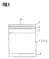
- Fig.1 illustrates the basic arrangement of a magnetic recording medium obtained according to one embodiment of the present invention.
- a substrate 1 of non-magnetic material which is preferably a polyester (PET) film of 3 to 20 »m thick is coated at top with a ferromagnetic metal thin film 2 of 0.1 to 0.2 »m formed of Co-Ni alloy by rhombic vapor deposition.
- the back of the substrate 1 is coated with a back coating layer 3 formed of a mixture of e.g. resin and carbon for enhancement of running performance.
- the ferromagnetic metal thin film 2 is covered with a protective layer 4 and a lubricant layer 5.
- the atomic ratio of the hydroxyl group to a primary component metal element, namely Co, contained in the ferromagnetic metal thin film 2 is less than 0.2:1 at the interface between the ferromagnetic metal thin film 2 and the protective layer 4.
- a magnetic recording medium 20a with no protective layer developed thereon is fed out from a supply roll while its tension is being controlled properly.
- a couple of pass rollers 22 and 24 which rotate and act as guides while the magnetic recording medium 20a and a magnetic recording medium 20b coated with a protective layer 4 run along respectively.
- a main drum 23 which is insulated from a main body of an apparatus and grounded via e.g. a coolant is provided for transfer of the magnetic recording medium 20 at a uniform speed by controlled rotating motion.
- the magnetic recording medium 20b coated with the protective layer 4 is rewound onto a take-up roll 25 at an equal tension to that in feeding out from the supply roll 21.
- the plasma power source 29 may supply a DC or AC voltage (at 50 Hz to 30 MHz) or a maximum of 7 kv produced by superimposition of such voltages.
- a gas feeding inlet 28 is provided for supply of reactive gas of e.g. H2, Ar, or CH, or vapor gas of e.g. ketone or alcohol group at a partial pressure of 0.001 to 0.5 Torr.
- the combination of the foregoing components 26 to 29 constitutes a plasma CVD device.
- a bias power source 30 is provided for supply of a charge to render the running magnetic recording medium 20 in close contact with the main drum 23.
- a heating device 31 consisting mainly of a heat source, e.g. a halogen lamp or heater, and a reflective plate for efficient use of heat, very-low-temperature panels 32 extending along the path of the magnetic recording medium 20, and a vacuum pump 34 for producing a vacuum in a vacuum chamber 33.
- a heat source e.g. a halogen lamp or heater
- a reflective plate for efficient use of heat
- very-low-temperature panels 32 extending along the path of the magnetic recording medium 20
- a vacuum pump 34 for producing a vacuum in a vacuum chamber 33.
- the magnetic recording medium 20a less the protective layer 4 is fed to run with its back wrapping around the main drum 23 during continuously traveling from the supply roll 21 to the take-up roll 25.
- the heating device 31 when its halogen lamp or heater is energized emits rays of thermal energy which are irradiated onto the surface of the ferromagnetic metal thin film 2 of the magnetic recording medium 20a as partially reflected by the reflective plate so that its temperature rises up. Accordingly, impurities, e.g. water trapped in the ferromagnetic metal thin film 2 under the atmospheric conditions are removed in the form of an out gas by heat towards the interior of the vacuum chamber 33.
- the out gas released is then absorbed by the very-low-temperature panels 32 and thus, the surface of the ferromagnetic metal thin film 2 becomes purified without involving recontamination of the magnetic recording medium 20a which is in turn transferred to a stage of development of the protective layer 4.
- a plasma of ionized substances generated by a reactive gas from the gas feeding inlet 28 and a specific rate of voltage,from the plasma power source 29 is fired from the plasma electrode 27 towards the magnetic recording medium 20a.
- the plasma upon reaching the ferromagnetic metal thin film 2 accumulates to develop the protective layer 4 on the same.
- the surface of the ferromagnetic metal thin film 2 carries a minimum amount of hydroxyl contents and remains free from impurities. Accordingly, the protective layer 4 can securely be bonded in chemical coupling onto the ferromagnetic metal thin film 2.
- An excess of the reactive gas escaped from between the plasma nozzle 26 and the main drum 23 where the magnetic recording medium 20 closely runs through is constantly absorbed by the very-low-temperature panels 32 arranged along the running magnetic recording medium 20, whereby recontamination by the gas on both the uncoated ferromagnetic metal thin film 2 and the finished protective layer 4 will be avoided. Consequently, the still frame life and resistance to corrosion of the magnetic recording medium 20 will be increased.
- the protective layer 4 of each magnetic recording medium 20 to be used for measurement of practical performance is a diamond-like carbon layer of about 100 angstroms in thickness which is developed on the surface of the magnetic recording medium heated to 80°C by a heater, while the very-low-temperature panels being set to -150°C, and then, coated with a lubricant layer 5 of about 30 ⁇ thick formed mainly of fluorine-containing carboxylic acid.
- the atomic ratio of the hydroxyl group to the primary component metal element, Co,of the ferromagnetic metal thin film 2 was measured 0.16 to 0.19 at the interface between the ferromagnetic metal thin film 2 and the protective layer 4.
- Example 2 employing a heater roller 35 for heating procedure will be described referring to Fig.3.
- Example 2 This embodiment is distinguished from Example 1 by the fact that the heating device, e.g. a heater or halogen lamp, is replaced with the heater roller 35.
- the other components of Example 2 are identical to those of Example 1 and will be denoted by like numerals and no further explained.
- a magnetic recording medium 20a less a protective layer 4 is fed from a supply roller 21 and transferred through a pass roller 22 to the heater roller 35.
- the magnetic recording medium 20a upon reaching the heater roller 35 is heated up by the same and thus, releases impurities, which have been trapped under the atmospheric conditions and include water or moisture, in a gaseous form towards the interior of a vacuum chamber 33.
- the magnetic recording medium 20a with its surface purified runs further to a stage of protective layer development where its ferromagnetic metal thin film 2 is coated with the protective layer 4 developed by application of plasma ion currents similar to the procedure in Example 1.
- the magnetic recording medium 20 is heated up from the back so that it can release impurities from not only the surface but also the inside deep.
- the bonding strength between the ferromagnetic metal thin film 2 and the protective layer 4 becomes great.
- the still frame life and resistance to corrosion of the finished magnetic recording medium 20 will be increased.
- the heater roller 35 was maintained at a temperature of 80°C and the other conditions were the same as of Example 1.
- the atomic ratio of the hydroxyl group to the primary component metal element, Co, of the ferromagnetic metal thin film 2 was measured 0.15 to 0.17 at the interface between the ferromagnetic metal thin film 2 and the protective layer 4.
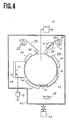
- Fig. 4 illustrates a schematic view of an apparatus used for carrying out Example 3 with a method of producing a magnetic recording medium according to another embodiment of the present invention.
- a tape of non-magnetic base material 20c on which no magnetic layer nor protective layer is formed is fed out from a supply roll 21 as being properly tensioned under control.
- a couple of pass rollers 22 and 24 which rotate and act as guides while the non-magnetic base material 20c and a magnetic recording medium 20 coated with a ferromagnetic metal thin film 2 and a protective layer 4 run along respectively.
- a main drum 23 which is insulated from a main body of the apparatus and grounded via e.g. a coolant is provided for transfer of the magnetic recording medium 20 at a uniform speed by controlled rotating motion.
- the magnetic recording medium 20b coated with the protective layer 4 is rewound onto a take-up roll 25 at an equal tension to that in feeding out from the supply roll 21.
- a mask 36 defining an area of vapor deposition, a shutter 37 adapted for being released when the vapor evaporation reaches a predetermined level, and a vapor source 38 for fusing a vapor deposition metal material to vapor are provided constituting in combination a vacuum processing device for development of the ferromagnetic metal thin film 2.
- the plasma power source 29 may supply a DC or AC voltage (at 50 Hz to 30 MHz) or a maximum power of 7 kv produced by superimposition of such voltages.
- a gas feeding inlet 28 is provided for supply of reactive gas of e.g. H2, Ar, or CH, or vapor gas of e.g. ketone or alcohol group at a partial pressure of 0.001 to 0.5 Torr.
- the combination of the foregoing components 26 to 29 constitutes a plasma CVD device.
- a bias power source 30 is provided for supply of a charge to render the running magnetic recording medium 20 in close contact with the main drum 23.
- a vacuum pump 34 is provided for producing a vacuum in a vacuum chamber 33.
- a non-magnetic base material 20c carrying no ferromagnetic metal thin film 2 is continuously fed to run from the supply roll 21 to the take-up roll 25.
- the heating device 31 when its halogen lamp or heater is energized emits rays of thermal energy which are irradiated onto the surface of the non-magnetic base material 20c as partially reflected by a reflective plate so that its temperature rises up. Accordingly, impurities, e.g. water, carried on or trapped in the non-magnetic base material 20c under the atmospheric conditions are removed by heat towards the interior of a vacuum chamber 33 in the form of an out gas.
- the out gas released is then absorbed by the very-low-temperature panels 32 and thus, the surface of the non-magnetic base material 20c becomes purified prior to development of both a ferromagnetic metal thin film 2 and a protective layer 4, without involving recontamination of the ferromagnetic metal thin film 2 of the magnetic recording medium 20b and the protective layer 4 of the magnetic recoding medium 20b. Accordingly, during the development, the ferromagnetic metal thin film 2 can securely be bonded onto the non-magnetic base material 20c. Similarly, the protective layer 4 can securely be bonded in chemical coupling onto the ferromagnetic metal thin film 2.
- an excess of the reactive gas escaped from between the plasma nozzle 26 and the main drum 23 where the magnetic recording medium 20 closely runs through is constantly absorbed by the very-low-temperature panels 32 extending along the paths of their respective magnetic recording mediums 20a and 20b, whereby recontamination by the gas on both the uncoated ferromagnetic metal thin film 2 and the finished protective layer 4 will be avoided. Consequently, the resistance to environmental change (or still frame life under low-moisture condition after storage in high-temperature and high-moisture conditions) of the magnetic recording medium 20 will be increased.
- the out gas released from the magnetic recording medium 20b is absorbed by the third very-low-temperature panel 32 and thus, the finished magnetic recording medium 20 is rewound on the take-up roll 25 without spoiling its protective layer 4. It is hence ensured to securely couple a lubricant layer 5 to the protective layer 4 of the magnetic recording medium 20 at the next step. Accordingly, undesired head clogging caused under a low moisture condition during use of the magnetic recording medium will be minimized.
- the magnetic recording medium 20 to be used for measurement of practical performance includes a Co-containing magnetic layer of about 1800 ⁇ thick as the ferromagnetic metal thin film 2, a diamond-like carbon layer of about 100 ⁇ thick as the protective layer 4, both being formed on the surface of the non-magnetic base material 20c which is heated to 80°C by the heating device while the very-low-temperature panels being set to -50°C, and a lubricant layer 5 of about 30 ⁇ thick formed mainly of fluorine-containing carboxylic acid.
- the atomic ratio of the hydroxyl group to the primary component metal element, Co, of the ferromagnetic metal thin film 2 was measured 0.09 to 0.10 at the interface between the ferromagnetic metal thin film 2 and the protective layer 4.
- Example 4 is distinguished from Example 3 by the fact that the very-low-temperature panels are set to -150°C.
- the procedure of producing a magnetic recording medium 20 and its corresponding arrangement for measurement of practical performance are identical to those of Example 3 and will no further be explained. In this case, the absorption by the very-low-temperature panels becomes enhanced, whereby the resistance to corrosion of the magnetic recording medium 20 will be more increased.
- the atomic ratio of the hydroxyl group to the primary component metal element, Co, of the ferromagnetic metal thin film 2 was measured 0.08 to 0.085 at the interface between the ferromagnetic metal thin film 2 and the protective layer 4.
- Comparison 1 For the purpose of comparison, a procedure designated as Comparison 1 was carried out in which a ferromagnetic metal thin film 2 was developed on a base material by a separate vacuum processing device and after exposed to the atmosphere, coated with a protective layer 4. Also, another comparative procedure of Comparison 2 was executed in which a ferromagnetic metal thin film 2 was developed in a like manner as of Comparison 1 and after removal of gas of trapped impurities by heating the magnetic recording medium 20a, coated with a protective layer 4. It would be understood that every protective layer 4 was covered with a lubricant layer 5 prior to measurement for practical performance of the finished magnetic recording medium.
- the hydroxyl content at the interface between the ferromagnetic metal thin film and the protective layer and the primary component metal element contained in the ferromagnetic metal thin film were measured by an X-ray photo-electron spectral analysis method. More particularly, after both the lubricant and protective layers of the magnetic recording medium 20 had been ion etched, the amount of Co and O(oxygen) elements at the interface were measured upon detection of the primary component metal element, Co, of the ferromagnetic metal thin film. The atomic ratio of OH radical to Co was calculated by dividing the intensity of hydroxyl contents by the intensity of Co through correction of the intensity of OH and Co with a sensitivity ratio. The result will be termed as a hydroxyl ratio hereinafter.
- the head clogging was examined using a 90-minute length of 8-mm magnetic recording tape 20 which was passed for recording video signals at a speed of 14 mm/sec under a temperature of 23°C and a relative humidity of 70% along a 40-mm diameter recording drum of a video taperecorder having two pairs of 30-»m projecting record/playback heads and a track pitch of about 20 »m and rotating at a relative speed of 3.8 m/sec.
- the clogging time was measured and converted to a value per 100 hours.
- the clogging time is defined as a finite duration throughout which a drop of more than 6 dB in the playback output continues.
- the length of still frame life was examined using a similar magnetic recording tape which was driven for recording under 23°C and 70% RH conditions and for playback under both 23°C/70%RH and 23°C/10%RH conditions while being loaded three times the common movement on the same video taperecorder. It was determined that the still frame life ends when no normal output is reproduced from the ferromagnetic metal thin film 2 of the recording medium 20 which is injured.
- the resistance to corrosion was examined using a magnetic recording medium 20 which was recorded on the same video taperecorder as in the still frame life measurement, left behind under 40°C and 90% conditions, and measured under 23° C and 10% RH conditions while about two times the load exerted during examining the still frame life was applied weekly. Table 1 shows the measurements recorded at the first and fourth week after starting.
- the still frame life is also improved as clarified in Examples where the hydroxyl ratio is less than 0.2.
- the head clogging is decreased because the bonding strength between the lubricant layer and the protective layer becomes increased. More specifically, unwanted water or moisture carried on and trapped in the magnetic recording medium is minimized by heating the non-magnetic base material prior to coating operation and utilizing the very-low-temperature panels and also, during production, the protective layer remains dried and prevented from undesired transfer of moisture from the non-magnetic base material and its back coating. Hence, the bonding strength between the lubricant layer and the protective layer is enhanced so that physical assaults on the magnetic recording medium by the heads during running can be lessened.
- the improvement in the still frame life and the resistance to corrosion results from a decrease in the amount of hydroxyl contents on the surface of the ferromagnetic metal thin film.
- the decrease of the hydroxyl group intends to discourage the shift of metal oxide to metal triggered by reduction with hydrogen ions generated during plasma application for development of the protective layer.
- the chemical bonding reaction of the metal oxide is enhanced and also, the oxidation of metal to hydroxide during storage under high-temperature and high-moisture conditions is avoided. As the result, the chemical bonding remains assured and no declination in the bonding strength will be permitted.
Description
- The present invention relates to a method of producing a magnetic recording medium comprising the steps of:
forming a ferromagnetic metal thin film on a non-magnetic substrate;
heating both the non-magnetic substrate and the ferromagnetic metal thin film by a heat source in a vacuum chamber; and
forming a protective layer developed on the ferromagnetic metal thin film by a CVD method in said chamber. - In particular, the present invention relates to a method of producing a magnetic recording medium of metal thin film type and more particularly, a magnetic recording medium capable of optimizing the property of a protective layer which is developed over a magnetic recording layer for improvement in the practical use.
- A magnetic recording medium of ferromagnetic metal has been known which is formed by developing a layer of metal alloy containing Co, Ni, Fe, or their combination on a substrate of non-magnetic material, e.g. polyester film, polyimid film, or other polymer film, by a conventional method such as vacuum vapor deposition, sputtering, ion plating, or the like. Such a known magnetic recording medium is capable of increasing the recording density as compared with a coating-type magnetic recording medium. For ensuring high density recording, it is essential that operational error during recording and reproducing is minimized, spacing loss between magnetic head and recording medium is eliminated, and practical durability is increased. However, the metal thin film type magnetic recording medium has a layer of thin film of metal material which is too thin to provide a desired degree of durability. Particularly, the thin film metal is low in the resistance to corrosion and will easily be affected. For improvement, EP-A-0.284.073 discloses a vertical magnetic recording medium comprising two magnetic films formed on a substrate, wherein the second magnetic film covers the first magnetic film for protecting it against corrosion and abrasion. Other techniques also have been proposed in which the thin film of metal material is coated with a protective layer which is in turn covered with a lubricant layer as a top coating. Also, an improved method has been invented by us (as described in U.S. Patent No. 5,322,716 in which prior to development of a protective layer, impurities including occluded water are removed in the form of an out gas from the thin film of ferromagnetic metal material by heating so that the bonding strength between the ferromagnetic metal thin film and the protective layer can be increased.
- Unfortunately, the out gas removed from the magnetic recording medium tends to pollute the surface of the protective layer, thus interrupting the coupling between the protective layer and the lubricant layer. This will result in head clogging during use of the magnetic recording medium. Also, moisture released from a non-magnetic substrate of the magnetic recording medium is trapped between the ferromagnetic metal thin film and the protective layer at a stage of forming the protective layer, reducing the bonding strength inbetween. As the result, the still frame life (or resistance to corrosion) of the finished magnetic recording medium after storage under high-temperature and high-moisture conditions will be declined.
- JP-A-01.189.021 discloses a forming method of a magnetic recording medium, in which a ferromagnetic metal film is formed on a non-magnetic substrate, a protective layer is formed on the ferromagnetic metal film, and then the magnetic recording medium is heated in hydrogen atmosphere. Forming the ferromagnetic metal film and forming the protective layer are performed in different vacuum chambers. However, it is not sufficient to obtain that the surface of the ferromagnetic metal thin film remains free from impurities at a higher degree. This is disadvantageous to the quality of the magnetic recording medium. It was found that the hydroxyl group (OH radical) existing at the interface between the ferromagnetic metal thin film and the protective layer exhibited an atomic ratio of more than 0.2 to a primary component metal element contained in the ferromagnetic metal thin film.
- It is an object of the present invention to provide a method of producing a magnetic recording medium which is improved in the resistance to corrosion and contributes to the reduction of head clogging in use, thus ensuring high reliability for practical operation.
- According to the invention this object is met by a method of producing a magnetic recording medium comprising the steps of:
forming a ferromagnetic metal thin film on a non-magnetic substrate;
heating both the non-magnetic substrate and the ferromagnetic metal thin film by a heat source in a vacuum chamber; and
forming a protective layer developed on the ferromagnetic metal thin film by a CVD method in said chamber,
characterized by passing the thin-film-formed substrate adjacent to a panel which is set to less than -50°C at least before or after forming the protective layer in said vacuum chamber. - The step of forming the ferromagnetic metal thin film on the non-magnetic substrate is preferably performed in said vacuum chamber. As the result, the atomic ratio of the hydroxyl group (OH radical) to a primary component metal element contained in the ferromagnetic metal thin film can be decreased at the interface between the ferromagnetic metal thin film and the protective layer.
- In particular, the atomic ratio of the hydroxyl group to the primary component metal element of the ferromagnetic metal thin film is reduced to less than 0.2. Accordingly, the magnetic recording medium will be much increased in the resistance to corrosion, thus contributing to the reduction of head clogging.
-
- Fig.1 is a cross sectional view showing the basic arrangement of a magnetic recording medium produced by the method according to the present invention;
- Fig.2 is a schematic view showing Example 1 of the embodiments of the present invention, in which while a magnetic recording medium having a ferromagnetic metal thin film formed on a non-magnetic substrate being heated by a heat source, e.g. a halogen lamp or heater and the resultant out gas being absorbed by very-low-temperature panels, a protective layer is developed on the ferromagnetic metal thin film of the magnetic recording medium;
- Fig.3 is a schematic view showing Example 2 of the embodiments of the present invention, in which while a magnetic recording medium having a ferromagnetic metal thin film formed on a non-magnetic substrate being heated by a heater roller and the resultant out gas being absorbed by very-low-temperature panels, a protective layer is developed on the ferromagnetic metal thin film of the magnetic recording medium;
- Fig. 4 is a schematic view showing Examples 3 and 4 of tne embodiments of the present invention, in which while a non-magnetic substrate of a magnetic recording medium being heated and the resultant out gas being absorbed by very-low-temperature panels, both a ferromagnetic metal thin film and a protective layer are developed on the non-magnetic substrate within a vacuum chamber.
- Fig.1 illustrates the basic arrangement of a magnetic recording medium obtained according to one embodiment of the present invention. As shown, a
substrate 1 of non-magnetic material which is preferably a polyester (PET) film of 3 to 20 »m thick is coated at top with a ferromagnetic metal thin film 2 of 0.1 to 0.2 »m formed of Co-Ni alloy by rhombic vapor deposition. Also, the back of thesubstrate 1 is coated with aback coating layer 3 formed of a mixture of e.g. resin and carbon for enhancement of running performance. The ferromagnetic metal thin film 2 is covered with aprotective layer 4 and alubricant layer 5. In common, the atomic ratio of the hydroxyl group to a primary component metal element, namely Co, contained in the ferromagnetic metal thin film 2 is less than 0.2:1 at the interface between the ferromagnetic metal thin film 2 and theprotective layer 4. - As shown in Fig.2, a
magnetic recording medium 20a with no protective layer developed thereon is fed out from a supply roll while its tension is being controlled properly. There are provided a couple ofpass rollers magnetic recording medium 20a and a magnetic recording medium 20b coated with aprotective layer 4 run along respectively. Amain drum 23 which is insulated from a main body of an apparatus and grounded via e.g. a coolant is provided for transfer of themagnetic recording medium 20 at a uniform speed by controlled rotating motion. The magnetic recording medium 20b coated with theprotective layer 4 is rewound onto a take-up roll 25 at an equal tension to that in feeding out from thesupply roll 21. Also, provided are aplasma nozzle 26 for developing theprotective layer 4 and aplasma generating electrode 27 connected to aplasma power source 29. Theplasma power source 29 may supply a DC or AC voltage (at 50 Hz to 30 MHz) or a maximum of 7 kv produced by superimposition of such voltages. Agas feeding inlet 28 is provided for supply of reactive gas of e.g. H₂, Ar, or CH, or vapor gas of e.g. ketone or alcohol group at a partial pressure of 0.001 to 0.5 Torr. The combination of theforegoing components 26 to 29 constitutes a plasma CVD device. Also, abias power source 30 is provided for supply of a charge to render the runningmagnetic recording medium 20 in close contact with themain drum 23. In addition, there are provided aheating device 31 consisting mainly of a heat source, e.g. a halogen lamp or heater, and a reflective plate for efficient use of heat, very-low-temperature panels 32 extending along the path of themagnetic recording medium 20, and avacuum pump 34 for producing a vacuum in avacuum chamber 33. - The procedure of producing such a magnetic recording medium using the foregoing arrangement will now be described referring to Fig.2.
- It starts with producing a vacuum as low as 10⁻⁴ Torr in the
vacuum chamber 33 using thevacuum pump 34. Themagnetic recording medium 20a less theprotective layer 4 is fed to run with its back wrapping around themain drum 23 during continuously traveling from thesupply roll 21 to the take-up roll 25. Theheating device 31 when its halogen lamp or heater is energized emits rays of thermal energy which are irradiated onto the surface of the ferromagnetic metal thin film 2 of themagnetic recording medium 20a as partially reflected by the reflective plate so that its temperature rises up. Accordingly, impurities, e.g. water trapped in the ferromagnetic metal thin film 2 under the atmospheric conditions are removed in the form of an out gas by heat towards the interior of thevacuum chamber 33. The out gas released is then absorbed by the very-low-temperature panels 32 and thus, the surface of the ferromagnetic metal thin film 2 becomes purified without involving recontamination of themagnetic recording medium 20a which is in turn transferred to a stage of development of theprotective layer 4. At the stage of development of theprotective layer 4, a plasma of ionized substances generated by a reactive gas from thegas feeding inlet 28 and a specific rate of voltage,from theplasma power source 29 is fired from theplasma electrode 27 towards themagnetic recording medium 20a. The plasma upon reaching the ferromagnetic metal thin film 2 accumulates to develop theprotective layer 4 on the same. During application of the plasma, the surface of the ferromagnetic metal thin film 2 carries a minimum amount of hydroxyl contents and remains free from impurities. Accordingly, theprotective layer 4 can securely be bonded in chemical coupling onto the ferromagnetic metal thin film 2. An excess of the reactive gas escaped from between theplasma nozzle 26 and themain drum 23 where themagnetic recording medium 20 closely runs through is constantly absorbed by the very-low-temperature panels 32 arranged along the runningmagnetic recording medium 20, whereby recontamination by the gas on both the uncoated ferromagnetic metal thin film 2 and the finishedprotective layer 4 will be avoided. Consequently, the still frame life and resistance to corrosion of themagnetic recording medium 20 will be increased. - It is noted that the
protective layer 4 of eachmagnetic recording medium 20 to be used for measurement of practical performance is a diamond-like carbon layer of about 100 angstroms in thickness which is developed on the surface of the magnetic recording medium heated to 80°C by a heater, while the very-low-temperature panels being set to -150°C, and then, coated with alubricant layer 5 of about 30 Å thick formed mainly of fluorine-containing carboxylic acid. - As the result, the atomic ratio of the hydroxyl group to the primary component metal element, Co,of the ferromagnetic metal thin film 2 was measured 0.16 to 0.19 at the interface between the ferromagnetic metal thin film 2 and the
protective layer 4. - Example 2 employing a
heater roller 35 for heating procedure will be described referring to Fig.3. - This embodiment is distinguished from Example 1 by the fact that the heating device, e.g. a heater or halogen lamp, is replaced with the
heater roller 35. The other components of Example 2 are identical to those of Example 1 and will be denoted by like numerals and no further explained. - The method of magnetic recording medium production in this embodiment will now be described in conjunction with the operation of a corresponding apparatus. A
magnetic recording medium 20a less aprotective layer 4 is fed from asupply roller 21 and transferred through apass roller 22 to theheater roller 35. Themagnetic recording medium 20a upon reaching theheater roller 35 is heated up by the same and thus, releases impurities, which have been trapped under the atmospheric conditions and include water or moisture, in a gaseous form towards the interior of avacuum chamber 33. The resultant gas released is in turn absorbed by very-low-temperature panels 32 and then, themagnetic recording medium 20a with its surface purified runs further to a stage of protective layer development where its ferromagnetic metal thin film 2 is coated with theprotective layer 4 developed by application of plasma ion currents similar to the procedure in Example 1. During the plasma application, themagnetic recording medium 20 is heated up from the back so that it can release impurities from not only the surface but also the inside deep. As the result, the bonding strength between the ferromagnetic metal thin film 2 and theprotective layer 4 becomes great. Thus, the still frame life and resistance to corrosion of the finishedmagnetic recording medium 20 will be increased. - In test production of a
magnetic recording medium 20 to be examined for practical performance, theheater roller 35 was maintained at a temperature of 80°C and the other conditions were the same as of Example 1. - As the result, the atomic ratio of the hydroxyl group to the primary component metal element, Co, of the ferromagnetic metal thin film 2 was measured 0.15 to 0.17 at the interface between the ferromagnetic metal thin film 2 and the
protective layer 4. - Fig. 4 illustrates a schematic view of an apparatus used for carrying out Example 3 with a method of producing a magnetic recording medium according to another embodiment of the present invention.
- As shown in Fig. 4, a tape of
non-magnetic base material 20c on which no magnetic layer nor protective layer is formed is fed out from asupply roll 21 as being properly tensioned under control. There are provided a couple ofpass rollers non-magnetic base material 20c and amagnetic recording medium 20 coated with a ferromagnetic metal thin film 2 and aprotective layer 4 run along respectively. Amain drum 23 which is insulated from a main body of the apparatus and grounded via e.g. a coolant is provided for transfer of themagnetic recording medium 20 at a uniform speed by controlled rotating motion. The magnetic recording medium 20b coated with theprotective layer 4 is rewound onto a take-up roll 25 at an equal tension to that in feeding out from thesupply roll 21. Amask 36 defining an area of vapor deposition, ashutter 37 adapted for being released when the vapor evaporation reaches a predetermined level, and avapor source 38 for fusing a vapor deposition metal material to vapor are provided constituting in combination a vacuum processing device for development of the ferromagnetic metal thin film 2. Also, provided are aplasma nozzle 26 for developing theprotective layer 4 and aplasma generating electrode 27 connected to aplasma power source 29. Theplasma power source 29 may supply a DC or AC voltage (at 50 Hz to 30 MHz) or a maximum power of 7 kv produced by superimposition of such voltages. Agas feeding inlet 28 is provided for supply of reactive gas of e.g. H₂, Ar, or CH, or vapor gas of e.g. ketone or alcohol group at a partial pressure of 0.001 to 0.5 Torr. The combination of the foregoingcomponents 26 to 29 constitutes a plasma CVD device. Also, abias power source 30 is provided for supply of a charge to render the runningmagnetic recording medium 20 in close contact with themain drum 23. In addition, avacuum pump 34 is provided for producing a vacuum in avacuum chamber 33. - There are additionally provided a
heating device 31 for heating thenon-magnetic base material 20c and three very-low-temperature panels 32 extending along the paths of thenon-magnetic base material 20c, the ferromagnetic metal thin film 2 of the magnetic recording medium 20b, and theprotective layer 4 of the magnetic recording medium 20b respectively. - The procedure of producing such a magnetic recording medium using the foregoing arrangement will now be described referring to Fig. 4.
- A
non-magnetic base material 20c carrying no ferromagnetic metal thin film 2 is continuously fed to run from thesupply roll 21 to the take-up roll 25. Theheating device 31 when its halogen lamp or heater is energized emits rays of thermal energy which are irradiated onto the surface of thenon-magnetic base material 20c as partially reflected by a reflective plate so that its temperature rises up. Accordingly, impurities, e.g. water, carried on or trapped in thenon-magnetic base material 20c under the atmospheric conditions are removed by heat towards the interior of avacuum chamber 33 in the form of an out gas. The out gas released is then absorbed by the very-low-temperature panels 32 and thus, the surface of thenon-magnetic base material 20c becomes purified prior to development of both a ferromagnetic metal thin film 2 and aprotective layer 4, without involving recontamination of the ferromagnetic metal thin film 2 of the magnetic recording medium 20b and theprotective layer 4 of the magnetic recoding medium 20b. Accordingly, during the development, the ferromagnetic metal thin film 2 can securely be bonded onto thenon-magnetic base material 20c. Similarly, theprotective layer 4 can securely be bonded in chemical coupling onto the ferromagnetic metal thin film 2. Also, an excess of the reactive gas escaped from between theplasma nozzle 26 and themain drum 23 where themagnetic recording medium 20 closely runs through is constantly absorbed by the very-low-temperature panels 32 extending along the paths of their respectivemagnetic recording mediums 20a and 20b, whereby recontamination by the gas on both the uncoated ferromagnetic metal thin film 2 and the finishedprotective layer 4 will be avoided. Consequently, the resistance to environmental change (or still frame life under low-moisture condition after storage in high-temperature and high-moisture conditions) of themagnetic recording medium 20 will be increased. After development of theprotective layer 4, the out gas released from the magnetic recording medium 20b is absorbed by the third very-low-temperature panel 32 and thus, the finishedmagnetic recording medium 20 is rewound on the take-up roll 25 without spoiling itsprotective layer 4. It is hence ensured to securely couple alubricant layer 5 to theprotective layer 4 of themagnetic recording medium 20 at the next step. Accordingly, undesired head clogging caused under a low moisture condition during use of the magnetic recording medium will be minimized. - It is noted that the
magnetic recording medium 20 to be used for measurement of practical performance includes a Co-containing magnetic layer of about 1800 Å thick as the ferromagnetic metal thin film 2, a diamond-like carbon layer of about 100 Å thick as theprotective layer 4, both being formed on the surface of thenon-magnetic base material 20c which is heated to 80°C by the heating device while the very-low-temperature panels being set to -50°C, and alubricant layer 5 of about 30 Å thick formed mainly of fluorine-containing carboxylic acid. - As the result, the atomic ratio of the hydroxyl group to the primary component metal element, Co, of the ferromagnetic metal thin film 2 was measured 0.09 to 0.10 at the interface between the ferromagnetic metal thin film 2 and the
protective layer 4. - Example 4 is distinguished from Example 3 by the fact that the very-low-temperature panels are set to -150°C. The procedure of producing a
magnetic recording medium 20 and its corresponding arrangement for measurement of practical performance are identical to those of Example 3 and will no further be explained. In this case, the absorption by the very-low-temperature panels becomes enhanced, whereby the resistance to corrosion of themagnetic recording medium 20 will be more increased. - As the result, the atomic ratio of the hydroxyl group to the primary component metal element, Co, of the ferromagnetic metal thin film 2 was measured 0.08 to 0.085 at the interface between the ferromagnetic metal thin film 2 and the
protective layer 4. - For the purpose of comparison, a procedure designated as
Comparison 1 was carried out in which a ferromagnetic metal thin film 2 was developed on a base material by a separate vacuum processing device and after exposed to the atmosphere, coated with aprotective layer 4. Also, another comparative procedure of Comparison 2 was executed in which a ferromagnetic metal thin film 2 was developed in a like manner as ofComparison 1 and after removal of gas of trapped impurities by heating themagnetic recording medium 20a, coated with aprotective layer 4. It would be understood that everyprotective layer 4 was covered with alubricant layer 5 prior to measurement for practical performance of the finished magnetic recording medium. - It is noted that the hydroxyl content at the interface between the ferromagnetic metal thin film and the protective layer and the primary component metal element contained in the ferromagnetic metal thin film were measured by an X-ray photo-electron spectral analysis method. More particularly, after both the lubricant and protective layers of the
magnetic recording medium 20 had been ion etched, the amount of Co and O(oxygen) elements at the interface were measured upon detection of the primary component metal element, Co, of the ferromagnetic metal thin film. The atomic ratio of OH radical to Co was calculated by dividing the intensity of hydroxyl contents by the intensity of Co through correction of the intensity of OH and Co with a sensitivity ratio. The result will be termed as a hydroxyl ratio hereinafter. - The advantageous results of the foregoing embodiments will now be described referring to Table 1.
- More specifically, the assessment of
magnetic recording media 20 produced by the methods of the present invention and the other comparative prior art methods listed in Table 1 will be explained in the respects of head clogging under low moisture condition, length of still frame life under low moisture condition, and resistance to corrosion.
- The procedure of assessment for each respect will be described.
- The head clogging was examined using a 90-minute length of 8-mm
magnetic recording tape 20 which was passed for recording video signals at a speed of 14 mm/sec under a temperature of 23°C and a relative humidity of 70% along a 40-mm diameter recording drum of a video taperecorder having two pairs of 30-»m projecting record/playback heads and a track pitch of about 20 »m and rotating at a relative speed of 3.8 m/sec. After the magnetic recording tape was driven for playback for about 200 hours under 23°C and 10% RH conditions, the clogging time was measured and converted to a value per 100 hours. The clogging time is defined as a finite duration throughout which a drop of more than 6 dB in the playback output continues. - The length of still frame life was examined using a similar magnetic recording tape which was driven for recording under 23°C and 70% RH conditions and for playback under both 23°C/70%RH and 23°C/10%RH conditions while being loaded three times the common movement on the same video taperecorder. It was determined that the still frame life ends when no normal output is reproduced from the ferromagnetic metal thin film 2 of the
recording medium 20 which is injured. The resistance to corrosion was examined using amagnetic recording medium 20 which was recorded on the same video taperecorder as in the still frame life measurement, left behind under 40°C and 90% conditions, and measured under 23° C and 10% RH conditions while about two times the load exerted during examining the still frame life was applied weekly. Table 1 shows the measurements recorded at the first and fourth week after starting. - The magnetic recording media of Example 3 and 4 in which each coating is formed after the non-magnetic substrate has been heated are much improved in this respect.
- The still frame life is also improved as clarified in Examples where the hydroxyl ratio is less than 0.2.
- Accordingly, it can be explained that the head clogging is decreased because the bonding strength between the lubricant layer and the protective layer becomes increased. More specifically, unwanted water or moisture carried on and trapped in the magnetic recording medium is minimized by heating the non-magnetic base material prior to coating operation and utilizing the very-low-temperature panels and also, during production, the protective layer remains dried and prevented from undesired transfer of moisture from the non-magnetic base material and its back coating. Hence, the bonding strength between the lubricant layer and the protective layer is enhanced so that physical assaults on the magnetic recording medium by the heads during running can be lessened.
- Also, it would be understood that the improvement in the still frame life and the resistance to corrosion results from a decrease in the amount of hydroxyl contents on the surface of the ferromagnetic metal thin film. In more detail, the decrease of the hydroxyl group intends to discourage the shift of metal oxide to metal triggered by reduction with hydrogen ions generated during plasma application for development of the protective layer. Hence, the chemical bonding reaction of the metal oxide is enhanced and also, the oxidation of metal to hydroxide during storage under high-temperature and high-moisture conditions is avoided. As the result, the chemical bonding remains assured and no declination in the bonding strength will be permitted.
Claims (2)
- A method of producing a magnetic recording medium comprising the steps of:
forming a ferromagnetic metal thin film on a non-magnetic substrate;
heating both the non-magnetic substrate and the ferromagnetic metal thin film by a heat source in a vacuum chamber; and
forming a protective layer developed on the ferromagnetic metal thin film by a CVD method in said chamber,
characterized by passing the thin-film-formed substrate adjacent to a panel which is set to less than -50°C at least before or after forming the protective layer in said vacuum chamber. - A method of producing a magnetic recording medium according to claim 1,
wherein the step of forming the ferromagnetic metal thin film on the non-magnetic substrate is performed in said vacuum chamber.
Applications Claiming Priority (6)
| Application Number | Priority Date | Filing Date | Title |
|---|---|---|---|
| JP212547/90 | 1990-08-09 | ||
| JP21254790A JPH0495220A (en) | 1990-08-09 | 1990-08-09 | Production of magnetic recording medium |
| JP1149/91 | 1991-01-09 | ||
| JP3001149A JP2687730B2 (en) | 1991-01-09 | 1991-01-09 | Manufacturing method of magnetic recording medium |
| JP82274/91 | 1991-04-15 | ||
| JP3082274A JP2861450B2 (en) | 1991-04-15 | 1991-04-15 | Magnetic recording medium and method of manufacturing the same |
Publications (2)
| Publication Number | Publication Date |
|---|---|
| EP0470934A1 EP0470934A1 (en) | 1992-02-12 |
| EP0470934B1 true EP0470934B1 (en) | 1995-11-29 |
Family
ID=27274782
Family Applications (1)
| Application Number | Title | Priority Date | Filing Date |
|---|---|---|---|
| EP91810611A Expired - Lifetime EP0470934B1 (en) | 1990-08-09 | 1991-08-05 | Method of producing a magnetic recording medium |
Country Status (3)
| Country | Link |
|---|---|
| US (1) | US5451427A (en) |
| EP (1) | EP0470934B1 (en) |
| DE (1) | DE69114943T2 (en) |
Families Citing this family (4)
| Publication number | Priority date | Publication date | Assignee | Title |
|---|---|---|---|---|
| US5589263A (en) * | 1993-12-28 | 1996-12-31 | Matsushita Electric Industrial Co., Ltd. | Magnetic recording medium having a ferromagnetic metal thin film, a dry etched layer, a carbonaceous film, and a lubricant film |
| US5569523A (en) * | 1994-02-28 | 1996-10-29 | Matsushita Electric Industrial Co., Ltd. | Magnetic recording medium having a ferromagnetic thin film in which 70% to 90% of the total magnetic particles have residual magnetization vectors within ±10° of the easy axis direction |
| JP4336869B2 (en) * | 2001-11-27 | 2009-09-30 | 日本電気株式会社 | Vacuum film forming apparatus, vacuum film forming method, and battery electrode manufacturing method |
| TWI291047B (en) * | 2005-08-08 | 2007-12-11 | Ind Tech Res Inst | Method and apparatus for inspection flexible display medium layer |
Citations (2)
| Publication number | Priority date | Publication date | Assignee | Title |
|---|---|---|---|---|
| EP0284073A2 (en) * | 1987-03-24 | 1988-09-28 | Ube Industries, Ltd. | Vertical magnetic recording medium and method of manufacturing the same |
| EP0320241A2 (en) * | 1987-12-07 | 1989-06-14 | Hitachi Maxell Ltd. | Magnetic recording medium and process for preparing the same |
Family Cites Families (6)
| Publication number | Priority date | Publication date | Assignee | Title |
|---|---|---|---|---|
| US3213825A (en) * | 1959-12-31 | 1965-10-26 | Trw Inc | Vacuum deposition apparatus |
| JPH0770509B2 (en) * | 1982-10-08 | 1995-07-31 | 株式会社日立製作所 | Dry process equipment |
| JPS61210518A (en) * | 1985-03-13 | 1986-09-18 | Matsushita Electric Ind Co Ltd | Magnetic recording medium |
| US4833031A (en) * | 1986-03-20 | 1989-05-23 | Matsushita Electric Industrial Co., Ltd. | Magnetic recording medium |
| JPH0833995B2 (en) * | 1989-07-04 | 1996-03-29 | 松下電器産業株式会社 | Method of manufacturing magnetic recording medium |
| US5322716A (en) * | 1989-07-04 | 1994-06-21 | Matsushita Electric Industrial Co., Ltd. | Method for producing magnetic recording medium |
-
1991
- 1991-08-05 DE DE69114943T patent/DE69114943T2/en not_active Expired - Lifetime
- 1991-08-05 EP EP91810611A patent/EP0470934B1/en not_active Expired - Lifetime
-
1993
- 1993-04-16 US US08/046,712 patent/US5451427A/en not_active Expired - Lifetime
Patent Citations (2)
| Publication number | Priority date | Publication date | Assignee | Title |
|---|---|---|---|---|
| EP0284073A2 (en) * | 1987-03-24 | 1988-09-28 | Ube Industries, Ltd. | Vertical magnetic recording medium and method of manufacturing the same |
| EP0320241A2 (en) * | 1987-12-07 | 1989-06-14 | Hitachi Maxell Ltd. | Magnetic recording medium and process for preparing the same |
Also Published As
| Publication number | Publication date |
|---|---|
| DE69114943T2 (en) | 1996-05-15 |
| DE69114943D1 (en) | 1996-01-11 |
| EP0470934A1 (en) | 1992-02-12 |
| US5451427A (en) | 1995-09-19 |
Similar Documents
| Publication | Publication Date | Title |
|---|---|---|
| US4565734A (en) | Magnetic recording medium | |
| JPH0421929B2 (en) | ||
| EP0745974A1 (en) | Method for forming silica protective films | |
| EP0538855B1 (en) | Magnetic recording medium | |
| US5591481A (en) | Method of manufacturing a magnetic recording medium including forming a graft polymer lubricant layer by irradiating monomers with radicals or atomic gas | |
| US5589263A (en) | Magnetic recording medium having a ferromagnetic metal thin film, a dry etched layer, a carbonaceous film, and a lubricant film | |
| EP0470934B1 (en) | Method of producing a magnetic recording medium | |
| US5496595A (en) | Method for forming film by plasma CVD | |
| US5104685A (en) | Method of producing magnetic recording medium | |
| EP0563748B1 (en) | Method of forming film by plasma CVD | |
| US5322716A (en) | Method for producing magnetic recording medium | |
| JPH0437484B2 (en) | ||
| JPS62279521A (en) | Production of magnetic recording medium | |
| JP3208972B2 (en) | Magnetic recording media | |
| JP2861450B2 (en) | Magnetic recording medium and method of manufacturing the same | |
| EP0420533A2 (en) | Manufacturing method and manufacturing apparatus of magnetic recording medium | |
| US5750209A (en) | Method for producing magnetic recording medium and apparatus therefor | |
| EP1345213B1 (en) | Magnetic recording medium and method and apparatus for manufacturing the same | |
| JP2687730B2 (en) | Manufacturing method of magnetic recording medium | |
| JPH10320739A (en) | Magnetic record medium and its production | |
| JPH0833993B2 (en) | Method of manufacturing magnetic recording medium | |
| EP0436219A2 (en) | Method for making magnetic recording media | |
| JPH0833995B2 (en) | Method of manufacturing magnetic recording medium | |
| JPH0495220A (en) | Production of magnetic recording medium | |
| JP2005129157A (en) | Magnetic recording medium, its manufacturing method and manufacturing device |
Legal Events
| Date | Code | Title | Description |
|---|---|---|---|
| PUAI | Public reference made under article 153(3) epc to a published international application that has entered the european phase |
Free format text: ORIGINAL CODE: 0009012 |
|
| AK | Designated contracting states |
Kind code of ref document: A1 Designated state(s): DE FR GB |
|
| 17P | Request for examination filed |
Effective date: 19920706 |
|
| 17Q | First examination report despatched |
Effective date: 19930906 |
|
| GRAA | (expected) grant |
Free format text: ORIGINAL CODE: 0009210 |
|
| AK | Designated contracting states |
Kind code of ref document: B1 Designated state(s): DE FR GB |
|
| REF | Corresponds to: |
Ref document number: 69114943 Country of ref document: DE Date of ref document: 19960111 |
|
| ET | Fr: translation filed | ||
| PLBE | No opposition filed within time limit |
Free format text: ORIGINAL CODE: 0009261 |
|
| STAA | Information on the status of an ep patent application or granted ep patent |
Free format text: STATUS: NO OPPOSITION FILED WITHIN TIME LIMIT |
|
| 26N | No opposition filed | ||
| REG | Reference to a national code |
Ref country code: GB Ref legal event code: IF02 |
|
| REG | Reference to a national code |
Ref country code: GB Ref legal event code: 746 Effective date: 20100127 |
|
| PGFP | Annual fee paid to national office [announced via postgrant information from national office to epo] |
Ref country code: FR Payment date: 20100824 Year of fee payment: 20 Ref country code: DE Payment date: 20100728 Year of fee payment: 20 |
|
| PGFP | Annual fee paid to national office [announced via postgrant information from national office to epo] |
Ref country code: GB Payment date: 20100811 Year of fee payment: 20 |
|
| REG | Reference to a national code |
Ref country code: DE Ref legal event code: R071 Ref document number: 69114943 Country of ref document: DE |
|
| REG | Reference to a national code |
Ref country code: DE Ref legal event code: R071 Ref document number: 69114943 Country of ref document: DE |
|
| REG | Reference to a national code |
Ref country code: GB Ref legal event code: PE20 Expiry date: 20110804 |
|
| PG25 | Lapsed in a contracting state [announced via postgrant information from national office to epo] |
Ref country code: GB Free format text: LAPSE BECAUSE OF EXPIRATION OF PROTECTION Effective date: 20110804 |
|
| PG25 | Lapsed in a contracting state [announced via postgrant information from national office to epo] |
Ref country code: DE Free format text: LAPSE BECAUSE OF EXPIRATION OF PROTECTION Effective date: 20110806 |