EP0470657A2 - Antilock brake control method with step-down release control - Google Patents
Antilock brake control method with step-down release control Download PDFInfo
- Publication number
- EP0470657A2 EP0470657A2 EP91201873A EP91201873A EP0470657A2 EP 0470657 A2 EP0470657 A2 EP 0470657A2 EP 91201873 A EP91201873 A EP 91201873A EP 91201873 A EP91201873 A EP 91201873A EP 0470657 A2 EP0470657 A2 EP 0470657A2
- Authority
- EP
- European Patent Office
- Prior art keywords
- brake
- wheel
- motor
- pressure
- release
- Prior art date
- Legal status (The legal status is an assumption and is not a legal conclusion. Google has not performed a legal analysis and makes no representation as to the accuracy of the status listed.)
- Granted
Links
Images


Classifications
-
- B—PERFORMING OPERATIONS; TRANSPORTING
- B60—VEHICLES IN GENERAL
- B60T—VEHICLE BRAKE CONTROL SYSTEMS OR PARTS THEREOF; BRAKE CONTROL SYSTEMS OR PARTS THEREOF, IN GENERAL; ARRANGEMENT OF BRAKING ELEMENTS ON VEHICLES IN GENERAL; PORTABLE DEVICES FOR PREVENTING UNWANTED MOVEMENT OF VEHICLES; VEHICLE MODIFICATIONS TO FACILITATE COOLING OF BRAKES
- B60T8/00—Arrangements for adjusting wheel-braking force to meet varying vehicular or ground-surface conditions, e.g. limiting or varying distribution of braking force
- B60T8/32—Arrangements for adjusting wheel-braking force to meet varying vehicular or ground-surface conditions, e.g. limiting or varying distribution of braking force responsive to a speed condition, e.g. acceleration or deceleration
- B60T8/34—Arrangements for adjusting wheel-braking force to meet varying vehicular or ground-surface conditions, e.g. limiting or varying distribution of braking force responsive to a speed condition, e.g. acceleration or deceleration having a fluid pressure regulator responsive to a speed condition
- B60T8/42—Arrangements for adjusting wheel-braking force to meet varying vehicular or ground-surface conditions, e.g. limiting or varying distribution of braking force responsive to a speed condition, e.g. acceleration or deceleration having a fluid pressure regulator responsive to a speed condition having expanding chambers for controlling pressure, i.e. closed systems
- B60T8/4208—Debooster systems
- B60T8/4266—Debooster systems having an electro-mechanically actuated expansion unit, e.g. solenoid, electric motor, piezo stack
-
- B—PERFORMING OPERATIONS; TRANSPORTING
- B60—VEHICLES IN GENERAL
- B60T—VEHICLE BRAKE CONTROL SYSTEMS OR PARTS THEREOF; BRAKE CONTROL SYSTEMS OR PARTS THEREOF, IN GENERAL; ARRANGEMENT OF BRAKING ELEMENTS ON VEHICLES IN GENERAL; PORTABLE DEVICES FOR PREVENTING UNWANTED MOVEMENT OF VEHICLES; VEHICLE MODIFICATIONS TO FACILITATE COOLING OF BRAKES
- B60T8/00—Arrangements for adjusting wheel-braking force to meet varying vehicular or ground-surface conditions, e.g. limiting or varying distribution of braking force
- B60T8/17—Using electrical or electronic regulation means to control braking
- B60T8/176—Brake regulation specially adapted to prevent excessive wheel slip during vehicle deceleration, e.g. ABS
- B60T8/1761—Brake regulation specially adapted to prevent excessive wheel slip during vehicle deceleration, e.g. ABS responsive to wheel or brake dynamics, e.g. wheel slip, wheel acceleration or rate of change of brake fluid pressure
- B60T8/17616—Microprocessor-based systems
-
- B—PERFORMING OPERATIONS; TRANSPORTING
- B60—VEHICLES IN GENERAL
- B60T—VEHICLE BRAKE CONTROL SYSTEMS OR PARTS THEREOF; BRAKE CONTROL SYSTEMS OR PARTS THEREOF, IN GENERAL; ARRANGEMENT OF BRAKING ELEMENTS ON VEHICLES IN GENERAL; PORTABLE DEVICES FOR PREVENTING UNWANTED MOVEMENT OF VEHICLES; VEHICLE MODIFICATIONS TO FACILITATE COOLING OF BRAKES
- B60T8/00—Arrangements for adjusting wheel-braking force to meet varying vehicular or ground-surface conditions, e.g. limiting or varying distribution of braking force
- B60T8/32—Arrangements for adjusting wheel-braking force to meet varying vehicular or ground-surface conditions, e.g. limiting or varying distribution of braking force responsive to a speed condition, e.g. acceleration or deceleration
- B60T8/34—Arrangements for adjusting wheel-braking force to meet varying vehicular or ground-surface conditions, e.g. limiting or varying distribution of braking force responsive to a speed condition, e.g. acceleration or deceleration having a fluid pressure regulator responsive to a speed condition
- B60T8/50—Arrangements for adjusting wheel-braking force to meet varying vehicular or ground-surface conditions, e.g. limiting or varying distribution of braking force responsive to a speed condition, e.g. acceleration or deceleration having a fluid pressure regulator responsive to a speed condition having means for controlling the rate at which pressure is reapplied to or released from the brake
Definitions
- This invention relates to an antilock brake control method for the wheel brakes of a vehicle.
- an antilock brake control method seeks to operate wheel slip at or near the critical slip value.
- An antilock brake control method achieves this objective by detecting an incipient lock condition. Upon detecting an incipient lock condition, the antilock brake control method releases brake pressure at the wheel brake to allow recovery from the incipient lock condition. Upon recovery, brake pressure is re-applied. Criteria used to indicate an incipient lock condition includes excessive wheel deceleration and/or excessive wheel slip.
- One known antilock brake control method uses a (motor driven) pressure modulator in which a DC torque motor drives a piston in a cylinder whose volume is modulated to control the hydraulic brake pressure at the wheel brake.
- a DC torque motor drives a piston in a cylinder whose volume is modulated to control the hydraulic brake pressure at the wheel brake.
- the value of motor current is used as a representation of brake pressure and is controlled to provide control of the brake pressure.
- the value of motor current at this time is stored as a representation of the brake pressure producing the maximum tyre torque coexisting with the critical slip between the wheel and the road surface and the motor current is controlled to quickly retract the piston to release brake pressure to allow recovery from the incipient wheel lock condition.
- the motor current is controlled to extend the piston to re- apply brake pressure.
- the pressure is quickly established substantially at the brake pressure producing the maximum tyre torque by quickly establishing the motor current at a significant faction of the motor current stored at the time an incipient wheel lock condition was sensed.
- brake pressure is ramped at a controlled rate which may be a function of wheel slip and acceleration by ramping the motor current in direction applying brake pressure until an incipient wheel lock condition is again sensed after which the cycle is repeated.
- the motor current is controlled to quickly reduce the brake pressure when an incipient wheel lock condition is first sensed until the wheel parameters indicate the wheel is beginning to recover from the incipient wheel lock condition.
- the motor current is then controlled to maintain the brake pressure that existed at the time the wheel began recovering from the incipient wheel lock condition.
- waiting for the wheel parameters to indicate the wheel beginning to recover from the incipient wheel lock condition while the motor is being controlled at a high speed to rapidly reduce pressure may result in an over-release of the brake pressure thereby decreasing the braking efficiency.
- this invention provides for a step-down release of the brake pressure in response to a sensed incipient wheel lock condition which maximizes the braking efficiency during wheel lock controlled braking by preventing over-release of the brake pressure during the pressure release phase of the antilock brake cycle.
- the current to the motor of a (motor driven) pressure modulator of an antilock brake system is controlled at a high value in response to a sensed incipient wheel lock condition so as to rapidly release the brake pressure for a calibrated time period that is a function of wheel parameters to reduce brake pressure by an amount determined to effect a recovery from the incipient wheel lock condition under normal antilock controlled braking.
- the motor is braked so as to quickly halt its rotation and therefore the rapid pressure reduction by applying a motor brake current to the motor by controlling the motor current in the pressure apply direction.
- the duration of this rapid reduction of brake pressure and therefore the amount of pressure reduction is independent of a sensed recovery condition of the wheel and is based solely on an open loop calibration value determined to effect wheel recovery from the incipient wheel lock condition.
- the calibrated period of rapid brake pressure reduction is a function of wheel slip and wheel acceleration such that the time period of the rapid release of brake pressure and therefore the amount of pressure reduction is increased with increasing values of negative wheel acceleration and increasing wheel slip.
- the calibrated values of the time period are such that under normal antilock controlled braking, the resultant reduction in wheel brake pressure will effect a recovery from the incipient wheel lock condition.
- the magnitude of the motor brake current has a predetermined relationship to the motor current value at the time an incipient wheel lock condition was first sensed.
- the motor brake period defined by the duration of the motor brake current is a function of the duration of the rapid reduction in brake pressure. This function provides for longer motor brake periods as required to stop the motor which accelerates to higher speeds as the period of the high motor current for reducing wheel brake pressure increases.
- motor current is controlled to further release brake pressure at a lower rate to assure that under all conditions, the pressure will be reduced to a value to allow the wheel to recover from an incipient wheel lock condition.
- the invention further provides for bypassing the braking of the motor during severe incipient wheel lock conditions as represented by high slip and/or wheel deceleration values to assure rapid recovery from the incipient wheel lock condition.
- FIG. 1 An antilock brake control apparatus for a wheel of a motor vehicle is illustrated in Figure 1.
- the wheel includes a brake unit 10 operated by hydraulic brake pressure provided by a master cylinder 12 and a hydraulic boost unit 14 operated by the vehicle operator.
- the hydraulic fluid under pressure from the master cylinder 12 is provided to the brake unit 10 via brake lines 16 and a pressure modulator 18.
- the brake unit 10 is illustrated as a disc brake system that includes a caliper 20 located at a rotor 22.
- the wheel includes a wheel speed sensing assembly comprised of an exciter ring 24 rotated with the wheel and an electromagnetic sensor 26 which monitors the rotation of the exciter ring to provide a signal having a frequency proportional to the speed of the wheel.
- the wheel speed signal from the electromagnetic sensor 26 is provided to an electronic controller 28.
- the pressure modulator 18 is controlled by the electronic controller 28 to limit the brake pressure applied to the brake unit 10 to prevent wheel lockup.
- the pressure modulator 18 is illustrated in an inactive position where it is transparent to the braking system. This is the modulator home position during normal vehicle braking.
- the pressure modulator 18 is controlled to regulate the braking pressure to the wheel to maintain the braking of the wheel in a stable braking region.
- the pressure modulator 18 includes a motor 30 of the DC torque type whose output shaft drives a gear train 32 which, in turn, rotates a linear ball screw actuator 34.
- the linear ball screw actuator 34 contains a linearly stationary ball screw which, when rotated, linearly positions a nut 36.
- the nut 36 terminates in a piston 38 such that as the linear ball screw rotates, the piston 38 is either extended or retracted depending upon the direction of rotation of the motor 30.
- the pressure modulator 18 includes a housing 40 in which a cylinder 42 is formed.
- the piston 38 is reciprocally received within the cylinder 42.
- the cylinder 42 forms a portion of the fluid path between the master cylinder 12 and the brake unit 10.
- a (normally closed) ball check valve 44 which, when closed, isolates the master cylinder 12 from the brake unit 10.
- the ball check valve 44 is operated to an open position by the piston 38 when it is positioned in an extended position within the cylinder 42 as illustrated in Figure 1. This position is the home position of the pressure modulator 18.
- pressure at the wheel brake can be modulated to controlled values less than the master cylinder 12 pressure output until such time that the piston 38 again unseats the ball check valve 44 or until the pressure generated by the pressure modulator 18 at the brake unit 10 exceeds the fluid pressure output of the master cylinder 12.
- the ball check valve 44 is opened by the differential fluid pressure which limits the pressure of the brake unit 10 at the master cylinder 12 pressure. In this manner, the brake unit pressure can never exceed the operator established pressure.
- the electronic controller 28 of Figure 1 is illustrated and generally takes the form of a digital computer based controller.
- the electronic controller 28 includes a microprocessor 46 that is standard in form and includes the standard elements such as a central processing unit which executes an operating program permanently stored in a read-only memory which also stores tables and constants utilized in controlling the pressure modulator 18, an analogue-to-digital converter, a random access memory and input/output circuitry utilized to provide motor control signals to a motor driver interface circuit 48.
- the input/output circuit further includes input ports for receiving the wheel speed signal from the output of an interface and squaring circuit 53 having in turn an input from the electromagnetic sensor 26.
- the motor driver interface circuit 48 receives an enable signal EN, a motor current command signal I c and a forward/reverse direction signal DIR from the microprocessor 46 and controls an H-switch driver 50 to establish the commanded motor current I c in the required forward or reverse direction.
- the motor current to the motor 30 is controlled to the commanded value via a closed loop that responds to the actual motor current represented by the voltage across a sense resistor 52.
- the motor driver interface circuit 48 In response to the direction and motor current commands, the motor driver interface circuit 48 energizes the H-switch upper and lower forward gates via the upper gate signal UGF and lower gate signal LGF to control the motor 30 in the forward direction to apply brake pressure and energizes the H-switch upper and lower reverse gates via the signals UGR and LGR to control the motor 30 in the reverse direction to retract the piston 38 to reduce brake pressure at the brake unit 10.
- the microprocessor 46 may take the form of a Motorola single chip microcomputer MC68HC11.
- the motor driver interface circuit 48 and H-switch driver 50 may take the form of the driver illustrated in US Patent No. 4,835,695.
- the motor current is first stored as a measure of the brake pressure at the time the incipient wheel lock condition was first sensed, after which the motor current is controlled to quickly retract the piston 38 to release brake pressure to allow recovery from the incipient wheel lock condition.
- This reversal is accomplished by commanding a reverse motor direction and setting the command current at a maximum reverse current value.
- the motor driver interface circuit 48 responds to these commands by energizing the upper and lower reverse H-switch gate switches to drive the motor 30 in the reverse direction at the commanded current level.
- the reverse current for releasing brake pressure is provided for a calibrated predetermined time that is based upon the values of wheel deceleration and wheel slip to provide a corresponding brake pressure reduction determined to effect a recovery from the incipient wheel lock condition.
- the motor 30 is braked to terminate further pressure reduction by establishing the motor current in the forward direction by energizing the upper and lower forward H-switch gate switches at a current value that is a predetermined fraction of the previously stored current and for a predetermined motor brake period also based on the values of wheel deceleration and wheel slip. This forward current quickly stops the motor to terminate pressure reduction.
- the wheel will under normal anti-lock controlled braking recover from the incipient lockup condition during the motor brake period.
- the current to the motor 30 is again established at a lower value in direction to retract the piston 38 to again reduce the pressure at a lower rate to assure wheel recovery from the incipient wheel lock condition.
- the motor 30 is not braked at the end of the period of rapid release of the brake pressure. Instead, the motor current is reduced to a smaller value to continue to release brake pressure until the wheel recovers from the incipient wheel lock condition.
- the period of pressure release is independent of whether or not the wheel begins to recover from the incipient wheel lock condition.
- This period is calibrated as a function of the wheel parameters so that the wheel recovery from the incipient wheel lock condition will occur under normal conditions at least by the end of the subsequent motor brake period. This avoids the requirement of first sensing the wheel beginning to recover from the incipient wheel lock condition before terminating the release of brake pressure and thereby avoids the potential over-release of the brake pressure and the resulting decrease in efficiency of antilock controlled braking.
- an apply mode is indicated and the brake pressure is reapplied first to a significant fraction of the pressure existing at the time the incipient wheel lock condition was sensed and thereafter ramped by commanding a forward motor direction and setting the command current at an initial value that is a significant fraction of the stored current when the incipient wheel lock condition was sensed and thereafter ramping the value of the commanded motor current.
- the motor driver interface circuit 48 responds to these commands by energizing the upper and lower H-switch gate switches to drive the motor 30 in a forward direction at the command level.
- the brake pressure is ramped by ramping the commanded current level until such time that an incipient wheel lockup condition is again sensed at which time the cycle is repeated.
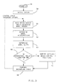
- antilock control functions are performed by executing a control cycle in response to each of repeated control cycle interrupts which are generated at predetermined fixed time intervals such as 5 milliseconds.
- the digital computer Upon the occurrence of a control cycle interrupt, the digital computer begins executing the functions embodied in the control cycle.
- wheel speed sensor information is read and wheel speed is computed for each of the vehicle wheels.
- the routine determines the individual wheel accelerations at step 62 and the individual wheel slip values at step 64. From the computed values of wheel acceleration and wheel slip, the program determines at step 66 whether or not those parameters represent the need for antilock brake pressure modulation for any wheel.
- step 68 If antilock control of brake pressure is not required, the program proceeds to perform background tasks at step 68. These tasks may include diagnostic functions as well as other functions. However, if step 66 determines that a need for antilock brake pressure modulation for any wheel is required, the program proceeds to a step 70 where antilock brake control functions are executed. Once those functions are executed, the program proceeds to the step 68 previously described.
- step 70 when antilock brake control is required establishes the general brake cycle as described wherein when the wheel slip and acceleration conditions represent an incipient wheel lockup condition, a pressure release mode is indicated and brake pressure is released to allow the wheel to recover from the incipient wheel lockup condition and when wheel acceleration and slip conditions represent a recovered condition, an apply mode is indicated and wheel pressure is re-applied and ramped until another incipient wheel lockup condition is sensed at which time the release mode is indicated and the cycle is repeated.
- each channel includes a pressure modulator 18.
- the routine of Figure 4 may be executed four times, once for each wheel with its related parameters.
- the rear brakes may be controlled by a single pressure modulator such that the routine of Figure 4 is then executed once for each front wheel and once for the combined rear wheels.
- step 70 of Figure 3 The antilock brake control functions of step 70 of Figure 3 is entered at step 72 and then proceeds to a step 74 that selects the required brake mode.
- the selection is made from a number of apply modes, such as 3, each having a related rate of increase in brake pressure as a function of wheel acceleration and wheel slip and a number of release modes such as 3 also as a function of wheel acceleration and wheel slip.
- the apply modes provide for higher rates of increase in brake pressure with increasing values of wheel acceleration with decreasing values of wheel slip.
- the release modes provide for control of release of the brake pressure in response to an incipient wheel lockup condition.
- each release mode has associated therewith a calibrated period of rapid pressure release to provide a calibrated pressure reduction. Except for one of the release modes associated with a severe incipient wheel lock condition, each remaining release mode also has associated therewith a calibrated motor brake period.
- the particular brake mode is determined via a lookup table stored in ROM storing the particular brake mode as a function of wheel acceleration and wheel slip.
- the stored brake modes establish a threshold between pressure apply and pressure release as a function of wheel acceleration and wheel slip.
- the lookup table indicates one of the brake release modes whereas if the combination of wheel acceleration and wheel slip represents a recovered condition, the lookup table indicates one of the brake apply modes.
- Step 76 determines whether the brake mode determined at step 72 is one of the apply modes. If not, indicating one of the release modes in response to an incipient lockup condition, the program proceeds to a step 78 which executes a brake release routine in response to the brake release mode established by step 74.
- the brake release routine 78 provides for control of the motor 30 to control brake pressure to allow wheel recovery from the incipient wheel lock condition.
- step 78 stores the commanded motor current as a representation of the motor current at the time the incipient wheel lockup condition is detected. This stored current value represents a measure of the brake pressure producing the maximum brake effort that corresponds to the wheel critical slip. Thereafter, with repeated executions of step 78 for the respective wheel, the brake pressure is released in accordance with the release mode determined at step 74.
- step 74 the lookup table indicates one of the pressure apply modes for the wheel acceleration and wheel slip conditions.
- step 76 determines that step 74 indicates a pressure apply mode
- the program proceeds to a step 80 where a brake apply routine is executed.
- the apply current is first set to a significant fraction of the current stored in step 78 when the incipient lockup condition was first detected.
- step 80 the apply current is ramped at a controlled rate to increase the brake pressure at the wheel brake until an incipient wheel lock condition is again sensed at step 74 when a release mode is determined via the lookup table in response to the wheel acceleration and slip values. Also at step 80, a release duration counter to be used in the brake release routine of step 78 is cleared.
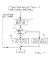
- the routine embodied in the brake release mode of step 78 for controlling the release of the brake pressure is illustrated in Figure 5.
- This routine enters from the brake release routine of step 78 at step 82 and then determines at step 84 whether the pressure release mode determined at step 74 is mode R1 associated with lower values of wheel slip/acceleration. Assuming that mode R1 was determined by step 74, the program proceeds to a step 86 to determine whether or not the duration of release of the brake pressure is greater than a calibration value KT1.
- the value of calibration value KT1 represents the time required for the pressure modulator 18 to reduce the brake pressure in response to a large commanded motor current value KM1 by a calibrated amount determined to effect recovery from the incipient wheel lock condition for the wheel slip and acceleration values associated with release mode R1.
- KT1 may be the period of three control loops effecting a brake pressure reduction of 2,068 kPa (300 psi). Assuming the release period is less than KT1, the program proceeds to a step 88 where the direction command to the motor driver interface circuit 48 is set to a direction to reduce brake pressure and the current command to the motor driver interface circuit 48 is set to KM1. KM1 is a large value providing high motor speed and rapid retraction of the piston 38. Thereafter, the program increments the release duration counter of step 90 after which the program returns to the brake release routine of step 78.
- step 74 determines the release mode as mode R1
- the program repeats the steps 84 through 90 until the release duration KT1 has expired indicating the pressure has been reduced by the amount determined to effect recovery from the incipient wheel lock condition.
- the program executes to a step 92 where the release duration is then compared to a second time period KT2 that is greater than the time period KT1 by an amount equal to the motor brake period associated with release mode R1.
- the motor brake period may be the period of five control loops.
- step 94 the program proceeds to a step 94 where the commanded direction of the motor 30 to the motor driver interface circuit 48 is set to forward direction and the current command is set to a predetermined fraction KFRAC of the current stored at step 78 when step 74 first determined a brake release mode indicating an incipient wheel lockup condition. The resulting current brakes the motor 30 to terminate pressure reduction. The release duration counter is then incremented at step 90. The motor 30 is braked in this manner until the expiration of the period KT2 unless a recovery condition is earlier sensed at step 74.
- step 74 Under normal antilock braking conditions, a recovery condition will be indicated by step 74 during the motor brake period established by KT2. However, if the period KT2 expires before a recovery condition is sensed, the program proceeds from step 92 to a step 96 wherein the motor 30 is commanded in a pressure release direction at a lower rate by commanding a small release current KM2 to the motor driver interface circuit 48. This provides for further release of brake pressure over repeated executions of step 96 to assure wheel recovery from the incipient lockup condition.
- step 98 determines whether or not step 74 has selected mode R2 associated with intermediate values of slip/acceleration. Assuming that mode R2 was selected by step 74, the program proceeds to a step 100 to determine whether or not the duration of release of the brake pressure is greater than a calibration value KT3.
- KT3 represents the time required for the pressure modulator 18 to reduce the brake pressure in response to the large commanded motor current value KM1 by a calibrated amount determined to effect recovery from the incipient wheel lock condition for the wheel slip and acceleration values associated with release mode R2.
- KT3 is greater than KT1 and provides for a larger pressure reduction associated with larger wheel slip/deceleration values.
- KT3 may be the period of six control loops effecting a wheel brake pressure reduction of 3,447 kPa (500 psi). Assuming the release period is less than KT3, the program proceeds to the step 88 where the direction command to the motor driver interface circuit 48 is set to reduce brake pressure and the current command to the motor driver interface circuit 48 is set to KM1. As indicated, this large current command provides high motor speed and rapid retraction of the piston 38. Thereafter, the program increments the release duration counter of step 90 after which the program returns to the brake release routine of step 78.
- step 74 determines the release mode as mode R2
- the program repeats the steps 84, 98, 100, 88 and 90 until the release duration KT3 has expired indicating the pressure has been reduced by the amount determined to effect recovery from the incipient wheel lock condition.
- the program executes to a step 102 where the release duration is then compared to a time period KT4 that is greater than the time period KT3 by an amount equal to the motor brake period associated with release mode R2.
- This brake period is larger than the brake period associated with the release mode R1 due to the higher motor speeds requiring longer brake periods to arrest the motor movement.
- the motor brake period may be the period of twelve control loops.
- step 94 the program proceeds to the step 94 where the commanded direction of the motor 30 to the motor driver interface circuit 48 is set to the pressure apply direction and the current command is set to the predetermined fraction KFRAC of the current stored at step 78 when step 74 first determined a brake release mode indicating an incipient wheel lockup condition. As in the case of release mode R1, the resulting current brakes the motor 30 to terminate pressure reduction. The release duration counter is then incremented at step 90. The motor 30 is braked in this manner until the expiration of the period KT4 unless a recovery condition is earlier sensed at step 74.
- step 74 Under normal antilock braking conditions, a recovery condition will be indicated by step 74 during the motor brake period established by KT4. However, if the period KT4 expires before a recovery condition is sensed, the program proceeds from step 102 to the step 96 wherein the motor 30 is commanded in a pressure release direction at a lower rate by commanding the small release current KM2 to the motor driver interface circuit 48. This provides for further release of brake pressure over repeated executions of step 96 to assure wheel recovery from the incipient lockup condition.
- step 98 if the pressure release mode determined at step 74 is not mode R3 associated with intermediate values of wheel slip/acceleration, the brake mode necessarily then is the remaining release mode R3 associated with more severe incipient wheel lock conditions. With these conditions, it is desirable to continuously release the brake pressure to effect a recovery from the incipient lockup condition. Accordingly, when release mode R3 is indicated, the motor 30 is not braked as in release modes R1 and R3.
- step 98 indicates release mode R3
- the program proceeds to a step 104 to determine whether or not the duration of rapid release of the wheel brake pressure is greater than a calibration value KT5.
- KT5 may be the period of five control loops.
- the program proceeds to the step 88 where the direction command to the motor driver interface circuit 48 is set to reduce brake pressure and the current command to the motor driver interface circuit 48 is set to KM1. As indicated, this large current command provides high motor speed and rapid retraction of the piston 38. Thereafter, the program increments the release duration counter of step 90 after which the program returns to the brake release routine of step 78.
- step 74 determines the release mode as mode R3
- the program repeats the steps 84, 98, 104, 88 and 90 until the release duration KT5 has expired. If the period KT5 expires before a recovery condition is sensed, the program proceeds from step 104 to the step 96 wherein release of brake pressure is continued by commanding the motor 30 in a pressure release direction at the lower rate by commanding the small release current KM2 to the motor driver interface circuit 48. This provides for further release of brake pressure over repeated executions of step 96 to assure wheel recovery from the incipient lockup condition.
- the brake pressure is controlled in response to a sensed incipient wheel lock condition so as to prevent an over release of brake pressure to maximize the braking efficiency of the brake system.
Landscapes
- Engineering & Computer Science (AREA)
- Physics & Mathematics (AREA)
- Fluid Mechanics (AREA)
- Transportation (AREA)
- Mechanical Engineering (AREA)
- Microelectronics & Electronic Packaging (AREA)
- Regulating Braking Force (AREA)
- Control Of Direct Current Motors (AREA)
Abstract
Description
- This invention relates to an antilock brake control method for the wheel brakes of a vehicle.
- When the brakes of a vehicle are applied, a tyre torque is generated between the wheel and the road surface that is dependent upon various parameters which include the wheel surface condition and the amount of slip between the wheel and the road surface. This tyre torque increases as slip increases until a critical value of slip is surpassed. Beyond the critical value of slip, the tyre torque decreases and the wheel rapidly approaches lockup. Therefore, to achieve stable braking, an antilock brake control method seeks to operate wheel slip at or near the critical slip value.
- An antilock brake control method achieves this objective by detecting an incipient lock condition. Upon detecting an incipient lock condition, the antilock brake control method releases brake pressure at the wheel brake to allow recovery from the incipient lock condition. Upon recovery, brake pressure is re-applied. Criteria used to indicate an incipient lock condition includes excessive wheel deceleration and/or excessive wheel slip.
- One known antilock brake control method uses a (motor driven) pressure modulator in which a DC torque motor drives a piston in a cylinder whose volume is modulated to control the hydraulic brake pressure at the wheel brake. In this method, because of the relationship between motor current, motor torque and motor load represented by the hydraulic brake pressure on the head of the piston while brake pressure is being applied, the value of motor current is used as a representation of brake pressure and is controlled to provide control of the brake pressure.
- In one such method, when an incipient wheel lock condition is sensed, the value of motor current at this time is stored as a representation of the brake pressure producing the maximum tyre torque coexisting with the critical slip between the wheel and the road surface and the motor current is controlled to quickly retract the piston to release brake pressure to allow recovery from the incipient wheel lock condition. When a recovery from the incipient wheel lock condition is sensed, the motor current is controlled to extend the piston to re- apply brake pressure. In re-applying the brake pressure, the pressure is quickly established substantially at the brake pressure producing the maximum tyre torque by quickly establishing the motor current at a significant faction of the motor current stored at the time an incipient wheel lock condition was sensed. Thereafter, brake pressure is ramped at a controlled rate which may be a function of wheel slip and acceleration by ramping the motor current in direction applying brake pressure until an incipient wheel lock condition is again sensed after which the cycle is repeated.
- In the pressure release phase of this antilock braking cycle, it is desirable to rapidly reduce brake pressure when an incipient wheel lock condition is sensed in order to prevent the wheel from locking. This may be provided in the motor driven, modulator based, antilock brake control method, as set forth above by applying maximum current through the motor in the direction causing retraction of the piston. However, to maximize braking efficiency, it is desirable to prevent an excessive decrease in the brake pressure as the pressure is reduced. To maximize the braking efficiency, the brake pressure should be reduced only enough to effect wheel recovery from the incipient wheel lock condition and return the wheel to the stable braking region. Accordingly, during the release phase of the antilock braking cycle, it is desirable to quickly "step-down" the brake pressure to a value that will effect recovery from the incipient wheel lock condition, but not to some lower pressure value.
- In one known method of controlling the motor current to establish the step-down release of brake pressure when an incipient wheel lock condition is sensed, the motor current is controlled to quickly reduce the brake pressure when an incipient wheel lock condition is first sensed until the wheel parameters indicate the wheel is beginning to recover from the incipient wheel lock condition. The motor current is then controlled to maintain the brake pressure that existed at the time the wheel began recovering from the incipient wheel lock condition. However, in this form of establishing the step-down pressure, waiting for the wheel parameters to indicate the wheel beginning to recover from the incipient wheel lock condition while the motor is being controlled at a high speed to rapidly reduce pressure may result in an over-release of the brake pressure thereby decreasing the braking efficiency. Additionally, as a result of the high motor speed and system inertia, a further pressure drop will occur subsequent to the detection of the recovery condition thereby adding to the potential over-release in brake pressure. Examples of the prior art can be found in US Patent Nos. 4,807,134 and 4,664,453.
- In general, this invention provides for a step-down release of the brake pressure in response to a sensed incipient wheel lock condition which maximizes the braking efficiency during wheel lock controlled braking by preventing over-release of the brake pressure during the pressure release phase of the antilock brake cycle.
- To this end, a method in accordance with the present invention is characterised by the features specified in the characterising portion of
claim 1. - In accordance with this invention, the current to the motor of a (motor driven) pressure modulator of an antilock brake system is controlled at a high value in response to a sensed incipient wheel lock condition so as to rapidly release the brake pressure for a calibrated time period that is a function of wheel parameters to reduce brake pressure by an amount determined to effect a recovery from the incipient wheel lock condition under normal antilock controlled braking. After the calibrated time period, the motor is braked so as to quickly halt its rotation and therefore the rapid pressure reduction by applying a motor brake current to the motor by controlling the motor current in the pressure apply direction. The duration of this rapid reduction of brake pressure and therefore the amount of pressure reduction is independent of a sensed recovery condition of the wheel and is based solely on an open loop calibration value determined to effect wheel recovery from the incipient wheel lock condition. By this calibration and by application of a motor current for braking the motor to halt the pressure reduction, an excessive release in pressure is prevented and braking efficiency of the brake system during antilock controlled braking is maximized.
- In one form of the invention, the calibrated period of rapid brake pressure reduction is a function of wheel slip and wheel acceleration such that the time period of the rapid release of brake pressure and therefore the amount of pressure reduction is increased with increasing values of negative wheel acceleration and increasing wheel slip. The calibrated values of the time period are such that under normal antilock controlled braking, the resultant reduction in wheel brake pressure will effect a recovery from the incipient wheel lock condition.
- In another aspect of the invention, the magnitude of the motor brake current has a predetermined relationship to the motor current value at the time an incipient wheel lock condition was first sensed. In a further aspect of the invention, the motor brake period defined by the duration of the motor brake current is a function of the duration of the rapid reduction in brake pressure. This function provides for longer motor brake periods as required to stop the motor which accelerates to higher speeds as the period of the high motor current for reducing wheel brake pressure increases.
- In a further aspect of the invention, at the end of the motor brake period, if the wheel has not recovered from the incipient wheel lock condition, motor current is controlled to further release brake pressure at a lower rate to assure that under all conditions, the pressure will be reduced to a value to allow the wheel to recover from an incipient wheel lock condition.
- The invention further provides for bypassing the braking of the motor during severe incipient wheel lock conditions as represented by high slip and/or wheel deceleration values to assure rapid recovery from the incipient wheel lock condition.
- The present invention will now be described, by way of example, with reference to the following description of the preferred embodiment of the invention, and the accompanying drawings, in which:-
- Figure 1 is a diagram of a braking system of a vehicle including a pressure modulator for limiting the brake pressure for antilock brake control;
- Figure 2 is a diagram of the electronic controller of Figure 1 for controlling the current to the motor of the pressure modulator of Figure 1; and
- Figures 3, 4 and 5 are flow diagrams illustrating the operation of the electronic controller of Figure 1 in accordance with the principles of this invention.
- An antilock brake control apparatus for a wheel of a motor vehicle is illustrated in Figure 1. In general, the wheel includes a
brake unit 10 operated by hydraulic brake pressure provided by amaster cylinder 12 and ahydraulic boost unit 14 operated by the vehicle operator. The hydraulic fluid under pressure from themaster cylinder 12 is provided to thebrake unit 10 viabrake lines 16 and apressure modulator 18. Thebrake unit 10 is illustrated as a disc brake system that includes acaliper 20 located at arotor 22. The wheel includes a wheel speed sensing assembly comprised of anexciter ring 24 rotated with the wheel and anelectromagnetic sensor 26 which monitors the rotation of the exciter ring to provide a signal having a frequency proportional to the speed of the wheel. The wheel speed signal from theelectromagnetic sensor 26 is provided to anelectronic controller 28. - The
pressure modulator 18 is controlled by theelectronic controller 28 to limit the brake pressure applied to thebrake unit 10 to prevent wheel lockup. Thepressure modulator 18 is illustrated in an inactive position where it is transparent to the braking system. This is the modulator home position during normal vehicle braking. In general, when theelectronic controller 28 senses a braking condition whereat the wheel is approaching an incipient wheel lock, thepressure modulator 18 is controlled to regulate the braking pressure to the wheel to maintain the braking of the wheel in a stable braking region. - The
pressure modulator 18 includes amotor 30 of the DC torque type whose output shaft drives agear train 32 which, in turn, rotates a linear ball screw actuator 34. The linear ball screw actuator 34 contains a linearly stationary ball screw which, when rotated, linearly positions anut 36. Thenut 36 terminates in apiston 38 such that as the linear ball screw rotates, thepiston 38 is either extended or retracted depending upon the direction of rotation of themotor 30. Thepressure modulator 18 includes ahousing 40 in which acylinder 42 is formed. Thepiston 38 is reciprocally received within thecylinder 42. Thecylinder 42 forms a portion of the fluid path between themaster cylinder 12 and thebrake unit 10. Included within this fluid path is a (normally closed)ball check valve 44 which, when closed, isolates themaster cylinder 12 from thebrake unit 10. Theball check valve 44 is operated to an open position by thepiston 38 when it is positioned in an extended position within thecylinder 42 as illustrated in Figure 1. This position is the home position of thepressure modulator 18. - When the
ball check valve 44 is opened, fluid communication is provided between themaster cylinder 12 and thebrake unit 10. This position is the normal inactive position of thepressure modulator 18 so that normal braking of the wheel of the vehicle is provided upon actuation of the brakes by the vehicle operator. However, when themotor 30 is operated by theelectronic controller 28 to modulate the braking pressure in thebrake unit 10, thepiston 38 is retracted allowing theball check valve 44 to seat and isolate themaster cylinder 12 from thebrake unit 10 as long as the pressure in thecylinder 42 is less than the brake pressure from themaster cylinder 12. Further retraction of thepiston 38 functions to increase the volume in thecylinder 42 thereby decreasing the brake pressure applied to thebrake unit 10. By controlling themotor 30, pressure at the wheel brake can be modulated to controlled values less than themaster cylinder 12 pressure output until such time that thepiston 38 again unseats theball check valve 44 or until the pressure generated by thepressure modulator 18 at thebrake unit 10 exceeds the fluid pressure output of themaster cylinder 12. When this latter condition exists, theball check valve 44 is opened by the differential fluid pressure which limits the pressure of thebrake unit 10 at themaster cylinder 12 pressure. In this manner, the brake unit pressure can never exceed the operator established pressure. - Referring to Figure 2, the
electronic controller 28 of Figure 1 is illustrated and generally takes the form of a digital computer based controller. Theelectronic controller 28 includes amicroprocessor 46 that is standard in form and includes the standard elements such as a central processing unit which executes an operating program permanently stored in a read-only memory which also stores tables and constants utilized in controlling thepressure modulator 18, an analogue-to-digital converter, a random access memory and input/output circuitry utilized to provide motor control signals to a motordriver interface circuit 48. The input/output circuit further includes input ports for receiving the wheel speed signal from the output of an interface and squaringcircuit 53 having in turn an input from theelectromagnetic sensor 26. - The motor
driver interface circuit 48 receives an enable signal EN, a motor current command signal Ic and a forward/reverse direction signal DIR from themicroprocessor 46 and controls an H-switch driver 50 to establish the commanded motor current Ic in the required forward or reverse direction. The motor current to themotor 30 is controlled to the commanded value via a closed loop that responds to the actual motor current represented by the voltage across asense resistor 52. In response to the direction and motor current commands, the motordriver interface circuit 48 energizes the H-switch upper and lower forward gates via the upper gate signal UGF and lower gate signal LGF to control themotor 30 in the forward direction to apply brake pressure and energizes the H-switch upper and lower reverse gates via the signals UGR and LGR to control themotor 30 in the reverse direction to retract thepiston 38 to reduce brake pressure at thebrake unit 10. Themicroprocessor 46 may take the form of a Motorola single chip microcomputer MC68HC11. The motordriver interface circuit 48 and H-switch driver 50 may take the form of the driver illustrated in US Patent No. 4,835,695. - During a typical antilock brake control cycle established by the apparatus of Figures 1 and 2, when an incipient wheel lock condition is sensed, the motor current is first stored as a measure of the brake pressure at the time the incipient wheel lock condition was first sensed, after which the motor current is controlled to quickly retract the
piston 38 to release brake pressure to allow recovery from the incipient wheel lock condition. This reversal is accomplished by commanding a reverse motor direction and setting the command current at a maximum reverse current value. The motordriver interface circuit 48 responds to these commands by energizing the upper and lower reverse H-switch gate switches to drive themotor 30 in the reverse direction at the commanded current level. - In accordance with this invention, the reverse current for releasing brake pressure is provided for a calibrated predetermined time that is based upon the values of wheel deceleration and wheel slip to provide a corresponding brake pressure reduction determined to effect a recovery from the incipient wheel lock condition. After expiration of the predetermined time, the
motor 30 is braked to terminate further pressure reduction by establishing the motor current in the forward direction by energizing the upper and lower forward H-switch gate switches at a current value that is a predetermined fraction of the previously stored current and for a predetermined motor brake period also based on the values of wheel deceleration and wheel slip. This forward current quickly stops the motor to terminate pressure reduction. By establishing the proper relationship between the predetermined time that the reverse current is applied to release brake pressure and the deceleration and wheel slip values, the wheel will under normal anti-lock controlled braking recover from the incipient lockup condition during the motor brake period. However, if the arrangement does not sense recovery from the incipient wheel lockup condition during the motor brake period, the current to themotor 30 is again established at a lower value in direction to retract thepiston 38 to again reduce the pressure at a lower rate to assure wheel recovery from the incipient wheel lock condition. - In one form of the invention, for severe incipient wheel lock conditions represented by severe wheel slip values and/or wheel deceleration, the
motor 30 is not braked at the end of the period of rapid release of the brake pressure. Instead, the motor current is reduced to a smaller value to continue to release brake pressure until the wheel recovers from the incipient wheel lock condition. - In the release phase of the braking cycle as set forth above, the period of pressure release is independent of whether or not the wheel begins to recover from the incipient wheel lock condition. This period is calibrated as a function of the wheel parameters so that the wheel recovery from the incipient wheel lock condition will occur under normal conditions at least by the end of the subsequent motor brake period. This avoids the requirement of first sensing the wheel beginning to recover from the incipient wheel lock condition before terminating the release of brake pressure and thereby avoids the potential over-release of the brake pressure and the resulting decrease in efficiency of antilock controlled braking.
- When recovery from the incipient wheel lock condition is sensed, an apply mode is indicated and the brake pressure is reapplied first to a significant fraction of the pressure existing at the time the incipient wheel lock condition was sensed and thereafter ramped by commanding a forward motor direction and setting the command current at an initial value that is a significant fraction of the stored current when the incipient wheel lock condition was sensed and thereafter ramping the value of the commanded motor current. The motor
driver interface circuit 48 responds to these commands by energizing the upper and lower H-switch gate switches to drive themotor 30 in a forward direction at the command level. The brake pressure is ramped by ramping the commanded current level until such time that an incipient wheel lockup condition is again sensed at which time the cycle is repeated. - The operation of the
electronic controller 28 in controlling themotor 30 in accordance with this invention is illustrated in Figures 3 through 5. The read only memory of themicroprocessor 46 contains the instructions necessary to implement the algorithm as diagrammed in those figures. Referring first to Figure 3, when power is first applied from a vehicle battery 54 (Figure 1) such as when a conventional vehicle ignition switch (not illustrated) is rotated to its "on" position, the computer program is initiated at apoint 56 and then provides for system initialization atstep 58 which entails clearing registers, initializing various RAM variables to calibrated values and other functions. When the initialization routine is completed, the program proceeds to perform antilock brake control functions as required. These antilock control functions are performed by executing a control cycle in response to each of repeated control cycle interrupts which are generated at predetermined fixed time intervals such as 5 milliseconds. Upon the occurrence of a control cycle interrupt, the digital computer begins executing the functions embodied in the control cycle. First, atstep 60, wheel speed sensor information is read and wheel speed is computed for each of the vehicle wheels. Thereafter, the routine determines the individual wheel accelerations atstep 62 and the individual wheel slip values atstep 64. From the computed values of wheel acceleration and wheel slip, the program determines atstep 66 whether or not those parameters represent the need for antilock brake pressure modulation for any wheel. - If antilock control of brake pressure is not required, the program proceeds to perform background tasks at
step 68. These tasks may include diagnostic functions as well as other functions. However, ifstep 66 determines that a need for antilock brake pressure modulation for any wheel is required, the program proceeds to astep 70 where antilock brake control functions are executed. Once those functions are executed, the program proceeds to thestep 68 previously described. - The foregoing steps 60 through 70 are repeated once for each control cycle. Thus, when a control cycle interrupt occurs, a new cycle begins at
step 60 and the functions represented bysteps 60 through 70 are again repeated as previously described. Repeated executions ofstep 70 when antilock brake control is required establishes the general brake cycle as described wherein when the wheel slip and acceleration conditions represent an incipient wheel lockup condition, a pressure release mode is indicated and brake pressure is released to allow the wheel to recover from the incipient wheel lockup condition and when wheel acceleration and slip conditions represent a recovered condition, an apply mode is indicated and wheel pressure is re-applied and ramped until another incipient wheel lockup condition is sensed at which time the release mode is indicated and the cycle is repeated. - Referring to Figure 4, there is illustrated a general flow diagram of the antilock brake control functions executed once for each braking channel where each channel includes a
pressure modulator 18. Where the four wheels of the vehicle are controlled independently, this requires the routine of Figure 4 to be executed four times, once for each wheel with its related parameters. In another arrangement, the rear brakes may be controlled by a single pressure modulator such that the routine of Figure 4 is then executed once for each front wheel and once for the combined rear wheels. - The antilock brake control functions of
step 70 of Figure 3 is entered atstep 72 and then proceeds to astep 74 that selects the required brake mode. In general, the selection is made from a number of apply modes, such as 3, each having a related rate of increase in brake pressure as a function of wheel acceleration and wheel slip and a number of release modes such as 3 also as a function of wheel acceleration and wheel slip. The apply modes provide for higher rates of increase in brake pressure with increasing values of wheel acceleration with decreasing values of wheel slip. The release modes provide for control of release of the brake pressure in response to an incipient wheel lockup condition. For example, each release mode has associated therewith a calibrated period of rapid pressure release to provide a calibrated pressure reduction. Except for one of the release modes associated with a severe incipient wheel lock condition, each remaining release mode also has associated therewith a calibrated motor brake period. - In this embodiment, the particular brake mode is determined via a lookup table stored in ROM storing the particular brake mode as a function of wheel acceleration and wheel slip. The stored brake modes establish a threshold between pressure apply and pressure release as a function of wheel acceleration and wheel slip. When the combination of wheel acceleration and wheel slip represents an incipient wheel lockup condition, the lookup table indicates one of the brake release modes whereas if the combination of wheel acceleration and wheel slip represents a recovered condition, the lookup table indicates one of the brake apply modes.
-
Step 76 then determines whether the brake mode determined atstep 72 is one of the apply modes. If not, indicating one of the release modes in response to an incipient lockup condition, the program proceeds to astep 78 which executes a brake release routine in response to the brake release mode established bystep 74. In general, thebrake release routine 78 provides for control of themotor 30 to control brake pressure to allow wheel recovery from the incipient wheel lock condition. - When an incipient wheel lockup condition is first indicated by
step 74 first indicating a brake release mode, thestep 78 stores the commanded motor current as a representation of the motor current at the time the incipient wheel lockup condition is detected. This stored current value represents a measure of the brake pressure producing the maximum brake effort that corresponds to the wheel critical slip. Thereafter, with repeated executions ofstep 78 for the respective wheel, the brake pressure is released in accordance with the release mode determined atstep 74. - Repeated executions of the
brake release routine 78 results in the wheel recovering from the incipient lock condition. This recovery condition is detected atstep 74 when the lookup table indicates one of the pressure apply modes for the wheel acceleration and wheel slip conditions. Whenstep 76 determines thatstep 74 indicates a pressure apply mode, the program proceeds to astep 80 where a brake apply routine is executed. In this routine, the apply current is first set to a significant fraction of the current stored instep 78 when the incipient lockup condition was first detected. Thereafter upon repeated executions of thestep 80, the apply current is ramped at a controlled rate to increase the brake pressure at the wheel brake until an incipient wheel lock condition is again sensed atstep 74 when a release mode is determined via the lookup table in response to the wheel acceleration and slip values. Also atstep 80, a release duration counter to be used in the brake release routine ofstep 78 is cleared. - The routine embodied in the brake release mode of
step 78 for controlling the release of the brake pressure is illustrated in Figure 5. This routine enters from the brake release routine ofstep 78 atstep 82 and then determines atstep 84 whether the pressure release mode determined atstep 74 is mode R1 associated with lower values of wheel slip/acceleration. Assuming that mode R1 was determined bystep 74, the program proceeds to astep 86 to determine whether or not the duration of release of the brake pressure is greater than a calibration value KT1. The value of calibration value KT1 represents the time required for thepressure modulator 18 to reduce the brake pressure in response to a large commanded motor current value KM1 by a calibrated amount determined to effect recovery from the incipient wheel lock condition for the wheel slip and acceleration values associated with release mode R1. In one embodiment, KT1 may be the period of three control loops effecting a brake pressure reduction of 2,068 kPa (300 psi). Assuming the release period is less than KT1, the program proceeds to astep 88 where the direction command to the motordriver interface circuit 48 is set to a direction to reduce brake pressure and the current command to the motordriver interface circuit 48 is set to KM1. KM1 is a large value providing high motor speed and rapid retraction of thepiston 38. Thereafter, the program increments the release duration counter ofstep 90 after which the program returns to the brake release routine ofstep 78. - As long as
step 74 determines the release mode as mode R1, the program repeats thesteps 84 through 90 until the release duration KT1 has expired indicating the pressure has been reduced by the amount determined to effect recovery from the incipient wheel lock condition. When expiration of this time is sensed atstep 86, the program executes to astep 92 where the release duration is then compared to a second time period KT2 that is greater than the time period KT1 by an amount equal to the motor brake period associated with release mode R1. In one embodiment, the motor brake period may be the period of five control loops. Assuming that the time period KT2 has not expired, the program proceeds to astep 94 where the commanded direction of themotor 30 to the motordriver interface circuit 48 is set to forward direction and the current command is set to a predetermined fraction KFRAC of the current stored atstep 78 whenstep 74 first determined a brake release mode indicating an incipient wheel lockup condition. The resulting current brakes themotor 30 to terminate pressure reduction. The release duration counter is then incremented atstep 90. Themotor 30 is braked in this manner until the expiration of the period KT2 unless a recovery condition is earlier sensed atstep 74. - Under normal antilock braking conditions, a recovery condition will be indicated by
step 74 during the motor brake period established by KT2. However, if the period KT2 expires before a recovery condition is sensed, the program proceeds fromstep 92 to astep 96 wherein themotor 30 is commanded in a pressure release direction at a lower rate by commanding a small release current KM2 to the motordriver interface circuit 48. This provides for further release of brake pressure over repeated executions ofstep 96 to assure wheel recovery from the incipient lockup condition. - Returning to step 84, if the pressure release mode determined at
step 74 is not mode R1 associated with lower values of slip/acceleration, the program executesstep 98 which determines whether or not step 74 has selected mode R2 associated with intermediate values of slip/acceleration. Assuming that mode R2 was selected bystep 74, the program proceeds to astep 100 to determine whether or not the duration of release of the brake pressure is greater than a calibration value KT3. In general, KT3 represents the time required for thepressure modulator 18 to reduce the brake pressure in response to the large commanded motor current value KM1 by a calibrated amount determined to effect recovery from the incipient wheel lock condition for the wheel slip and acceleration values associated with release mode R2. In general, the value of KT3 is greater than KT1 and provides for a larger pressure reduction associated with larger wheel slip/deceleration values. In one embodiment, KT3 may be the period of six control loops effecting a wheel brake pressure reduction of 3,447 kPa (500 psi). Assuming the release period is less than KT3, the program proceeds to thestep 88 where the direction command to the motordriver interface circuit 48 is set to reduce brake pressure and the current command to the motordriver interface circuit 48 is set to KM1. As indicated, this large current command provides high motor speed and rapid retraction of thepiston 38. Thereafter, the program increments the release duration counter ofstep 90 after which the program returns to the brake release routine ofstep 78. - As long as
step 74 determines the release mode as mode R2, the program repeats thesteps step 100, the program executes to astep 102 where the release duration is then compared to a time period KT4 that is greater than the time period KT3 by an amount equal to the motor brake period associated with release mode R2. This brake period is larger than the brake period associated with the release mode R1 due to the higher motor speeds requiring longer brake periods to arrest the motor movement. In one embodiment, the motor brake period may be the period of twelve control loops. Assuming that the time period KT4 has not expired, the program proceeds to thestep 94 where the commanded direction of themotor 30 to the motordriver interface circuit 48 is set to the pressure apply direction and the current command is set to the predetermined fraction KFRAC of the current stored atstep 78 whenstep 74 first determined a brake release mode indicating an incipient wheel lockup condition. As in the case of release mode R1, the resulting current brakes themotor 30 to terminate pressure reduction. The release duration counter is then incremented atstep 90. Themotor 30 is braked in this manner until the expiration of the period KT4 unless a recovery condition is earlier sensed atstep 74. - Under normal antilock braking conditions, a recovery condition will be indicated by
step 74 during the motor brake period established by KT4. However, if the period KT4 expires before a recovery condition is sensed, the program proceeds fromstep 102 to thestep 96 wherein themotor 30 is commanded in a pressure release direction at a lower rate by commanding the small release current KM2 to the motordriver interface circuit 48. This provides for further release of brake pressure over repeated executions ofstep 96 to assure wheel recovery from the incipient lockup condition. - Returning to step 98, if the pressure release mode determined at
step 74 is not mode R3 associated with intermediate values of wheel slip/acceleration, the brake mode necessarily then is the remaining release mode R3 associated with more severe incipient wheel lock conditions. With these conditions, it is desirable to continuously release the brake pressure to effect a recovery from the incipient lockup condition. Accordingly, when release mode R3 is indicated, themotor 30 is not braked as in release modes R1 and R3. Whenstep 98 indicates release mode R3, the program proceeds to astep 104 to determine whether or not the duration of rapid release of the wheel brake pressure is greater than a calibration value KT5. In one embodiment, KT5 may be the period of five control loops. Assuming the release period is less than KT5, the program proceeds to thestep 88 where the direction command to the motordriver interface circuit 48 is set to reduce brake pressure and the current command to the motordriver interface circuit 48 is set to KM1. As indicated, this large current command provides high motor speed and rapid retraction of thepiston 38. Thereafter, the program increments the release duration counter ofstep 90 after which the program returns to the brake release routine ofstep 78. - As long as
step 74 determines the release mode as mode R3, the program repeats thesteps step 104 to thestep 96 wherein release of brake pressure is continued by commanding themotor 30 in a pressure release direction at the lower rate by commanding the small release current KM2 to the motordriver interface circuit 48. This provides for further release of brake pressure over repeated executions ofstep 96 to assure wheel recovery from the incipient lockup condition. - In the foregoing manner, the brake pressure is controlled in response to a sensed incipient wheel lock condition so as to prevent an over release of brake pressure to maximize the braking efficiency of the brake system.
Claims (8)
Applications Claiming Priority (2)
| Application Number | Priority Date | Filing Date | Title |
|---|---|---|---|
| US07/565,308 US5106171A (en) | 1990-08-09 | 1990-08-09 | Antilock brake system with step-down release control |
| US565308 | 1990-08-09 |
Publications (3)
| Publication Number | Publication Date |
|---|---|
| EP0470657A2 true EP0470657A2 (en) | 1992-02-12 |
| EP0470657A3 EP0470657A3 (en) | 1993-01-13 |
| EP0470657B1 EP0470657B1 (en) | 1995-07-05 |
Family
ID=24258043
Family Applications (1)
| Application Number | Title | Priority Date | Filing Date |
|---|---|---|---|
| EP91201873A Expired - Lifetime EP0470657B1 (en) | 1990-08-09 | 1991-07-16 | Antilock brake control method with step-down release control |
Country Status (4)
| Country | Link |
|---|---|
| US (1) | US5106171A (en) |
| EP (1) | EP0470657B1 (en) |
| JP (1) | JP2709211B2 (en) |
| DE (1) | DE69110988T2 (en) |
Cited By (3)
| Publication number | Priority date | Publication date | Assignee | Title |
|---|---|---|---|---|
| DE4442084A1 (en) * | 1993-11-29 | 1995-06-01 | Aisin Seiki | Brake control device for car |
| DE4443730A1 (en) * | 1993-12-09 | 1995-06-14 | Aisin Seiki | Braking force regulator for motor vehicle |
| EP0678431A3 (en) * | 1991-10-08 | 1995-11-08 | Honda Motor Co Ltd |
Families Citing this family (10)
| Publication number | Priority date | Publication date | Assignee | Title |
|---|---|---|---|---|
| US5163743A (en) * | 1991-12-16 | 1992-11-17 | General Motors Corporation | Antilock brake control which induces rear brake lockup upon front brake lockup |
| US5264767A (en) * | 1992-01-21 | 1993-11-23 | General Motors Corporation | Electro-hydraulic control apparatus for improved hydraulic pressure control |
| US5281009A (en) * | 1992-08-19 | 1994-01-25 | General Motors Corporation | Antilock brake system with closed loop control of hold during release |
| US5487593A (en) * | 1994-11-23 | 1996-01-30 | Alliedsignal Inc. | Anti-lock braking system providing pump motor duty cycle based on deceleration and motor voltage feed back |
| US5494343A (en) * | 1994-11-23 | 1996-02-27 | Alliedsignal, Inc. | Method of detecting an inoperable pump motor in an anti-lock braking system |
| US7018001B2 (en) * | 2002-02-22 | 2006-03-28 | Delphi Technologies, Inc. | Fast mode release in a force generating apparatus |
| US6655756B2 (en) * | 2002-02-22 | 2003-12-02 | Delphi Technologies, Inc. | Fast mode release in a force generating apparatus using estimated actuator apply chamber pressure |
| EP1791738B1 (en) * | 2004-09-24 | 2010-12-29 | Continental Teves AG & Co. oHG | Method and device for supporting a brake system in case of reduced effectiveness |
| WO2009089551A2 (en) * | 2008-01-11 | 2009-07-16 | General Atomics | Braking system with linear actuator |
| JP6900881B2 (en) * | 2017-11-20 | 2021-07-07 | トヨタ自動車株式会社 | Electric brake control device |
Citations (2)
| Publication number | Priority date | Publication date | Assignee | Title |
|---|---|---|---|---|
| EP0084664A2 (en) * | 1982-01-22 | 1983-08-03 | Robert Bosch Gmbh | Antiskid system |
| US4664453A (en) * | 1985-10-21 | 1987-05-12 | General Motors Corporation | Anti-lock brake control system |
Family Cites Families (6)
| Publication number | Priority date | Publication date | Assignee | Title |
|---|---|---|---|---|
| US4576417A (en) * | 1985-02-04 | 1986-03-18 | General Motors Corporation | Power assisted braking system with wheel lock control |
| US4761741A (en) * | 1986-07-07 | 1988-08-02 | General Motors Corporation | Anti-lock brake control system |
| US4750124A (en) * | 1986-11-19 | 1988-06-07 | General Motors Corporation | Anti-lock brake control system |
| US4755946A (en) * | 1986-11-21 | 1988-07-05 | General Motors Corporation | Motor actuated anti-lock brake control system |
| US4756391A (en) * | 1987-07-06 | 1988-07-12 | General Motors Corporation | Brake system actuator with a return spring |
| US4807134A (en) * | 1987-07-09 | 1989-02-21 | General Motors Corporation | DC torque motor actuated anti-lock brake controller |
-
1990
- 1990-08-09 US US07/565,308 patent/US5106171A/en not_active Expired - Fee Related
-
1991
- 1991-07-16 DE DE69110988T patent/DE69110988T2/en not_active Expired - Fee Related
- 1991-07-16 EP EP91201873A patent/EP0470657B1/en not_active Expired - Lifetime
- 1991-08-09 JP JP3200530A patent/JP2709211B2/en not_active Expired - Lifetime
Patent Citations (2)
| Publication number | Priority date | Publication date | Assignee | Title |
|---|---|---|---|---|
| EP0084664A2 (en) * | 1982-01-22 | 1983-08-03 | Robert Bosch Gmbh | Antiskid system |
| US4664453A (en) * | 1985-10-21 | 1987-05-12 | General Motors Corporation | Anti-lock brake control system |
Cited By (8)
| Publication number | Priority date | Publication date | Assignee | Title |
|---|---|---|---|---|
| EP0678431A3 (en) * | 1991-10-08 | 1995-11-08 | Honda Motor Co Ltd | |
| US5573313A (en) * | 1991-10-08 | 1996-11-12 | Honda Giken Kogyo Kabushiki Kaisha | Method of and system for controlling brakes |
| US5577816A (en) * | 1991-10-08 | 1996-11-26 | Honda Giken Kogyo Kabushiki Kaisha | Method of and system for controlling brakes |
| DE4442084A1 (en) * | 1993-11-29 | 1995-06-01 | Aisin Seiki | Brake control device for car |
| DE4442084C2 (en) * | 1993-11-29 | 1999-11-25 | Aisin Seiki | Brake force control device for a vehicle |
| DE4443730A1 (en) * | 1993-12-09 | 1995-06-14 | Aisin Seiki | Braking force regulator for motor vehicle |
| US5597214A (en) * | 1993-12-09 | 1997-01-28 | Aisin Seiki Kabushiki Kaisha | Brake force control device for a vehicle |
| DE4443730C2 (en) * | 1993-12-09 | 1999-11-11 | Aisin Seiki | Anti-lock and traction slip-controlled electro-hydraulic brake system for a vehicle |
Also Published As
| Publication number | Publication date |
|---|---|
| EP0470657B1 (en) | 1995-07-05 |
| DE69110988T2 (en) | 1995-12-07 |
| JPH06219261A (en) | 1994-08-09 |
| DE69110988D1 (en) | 1995-08-10 |
| EP0470657A3 (en) | 1993-01-13 |
| JP2709211B2 (en) | 1998-02-04 |
| US5106171A (en) | 1992-04-21 |
Similar Documents
| Publication | Publication Date | Title |
|---|---|---|
| US5139315A (en) | Vehicle parking brake system and method | |
| EP0223358B1 (en) | Anti-lock brake control apparatus | |
| EP0470657B1 (en) | Antilock brake control method with step-down release control | |
| US5281009A (en) | Antilock brake system with closed loop control of hold during release | |
| US4835695A (en) | Add-on vehicle wheel slip controller | |
| US4881784A (en) | ABS pressure apply algorithm | |
| US5071199A (en) | Antilock brake system with motor current control | |
| US4750124A (en) | Anti-lock brake control system | |
| US4969756A (en) | Motor driven actuator speed control | |
| US5454630A (en) | Automotive antilock braking | |
| EP0397330B1 (en) | Vehicle traction control method | |
| US4673225A (en) | Anti-lock brake control system | |
| US5102207A (en) | Antilock brake system with motor current control of the pressure modulator | |
| US4917445A (en) | ABS variant nominal hold pressure | |
| US4783127A (en) | Anti-lock brake control system | |
| US5273349A (en) | Antilock brake system with motor current control | |
| US5315518A (en) | Method and apparatus for initializing antilock brake control on split coefficient surface | |
| EP0459548B1 (en) | Method and apparatus for controlling braking pressure applied to a vehicle brake | |
| CA1290372C (en) | Motor actuated anti-lock brake control system | |
| US5669679A (en) | Brake system control | |
| US5385394A (en) | Antilock brake system with controlled pressure augmentation | |
| US5308153A (en) | Antilock brake system with closed loop apply bump | |
| US5080447A (en) | Antilock brake controller with brake mode filter | |
| USRE33557E (en) | Anti-lock brake control system |
Legal Events
| Date | Code | Title | Description |
|---|---|---|---|
| PUAI | Public reference made under article 153(3) epc to a published international application that has entered the european phase |
Free format text: ORIGINAL CODE: 0009012 |
|
| AK | Designated contracting states |
Kind code of ref document: A2 Designated state(s): DE FR GB |
|
| PUAL | Search report despatched |
Free format text: ORIGINAL CODE: 0009013 |
|
| AK | Designated contracting states |
Kind code of ref document: A3 Designated state(s): DE FR GB |
|
| 17P | Request for examination filed |
Effective date: 19921224 |
|
| 17Q | First examination report despatched |
Effective date: 19940408 |
|
| GRAA | (expected) grant |
Free format text: ORIGINAL CODE: 0009210 |
|
| AK | Designated contracting states |
Kind code of ref document: B1 Designated state(s): DE FR GB |
|
| REF | Corresponds to: |
Ref document number: 69110988 Country of ref document: DE Date of ref document: 19950810 |
|
| ET | Fr: translation filed | ||
| PLBE | No opposition filed within time limit |
Free format text: ORIGINAL CODE: 0009261 |
|
| STAA | Information on the status of an ep patent application or granted ep patent |
Free format text: STATUS: NO OPPOSITION FILED WITHIN TIME LIMIT |
|
| 26N | No opposition filed | ||
| PGFP | Annual fee paid to national office [announced via postgrant information from national office to epo] |
Ref country code: GB Payment date: 20010618 Year of fee payment: 11 |
|
| PGFP | Annual fee paid to national office [announced via postgrant information from national office to epo] |
Ref country code: FR Payment date: 20010719 Year of fee payment: 11 |
|
| REG | Reference to a national code |
Ref country code: GB Ref legal event code: IF02 |
|
| PG25 | Lapsed in a contracting state [announced via postgrant information from national office to epo] |
Ref country code: GB Free format text: LAPSE BECAUSE OF NON-PAYMENT OF DUE FEES Effective date: 20020716 |
|
| GBPC | Gb: european patent ceased through non-payment of renewal fee |
Effective date: 20020716 |
|
| PG25 | Lapsed in a contracting state [announced via postgrant information from national office to epo] |
Ref country code: FR Free format text: LAPSE BECAUSE OF NON-PAYMENT OF DUE FEES Effective date: 20030331 |
|
| REG | Reference to a national code |
Ref country code: FR Ref legal event code: ST |
|
| PGFP | Annual fee paid to national office [announced via postgrant information from national office to epo] |
Ref country code: DE Payment date: 20050714 Year of fee payment: 15 |
|
| PG25 | Lapsed in a contracting state [announced via postgrant information from national office to epo] |
Ref country code: DE Free format text: LAPSE BECAUSE OF NON-PAYMENT OF DUE FEES Effective date: 20070201 |