EP0470525B1 - Power converter with shoot-through protection - Google Patents
Power converter with shoot-through protection Download PDFInfo
- Publication number
- EP0470525B1 EP0470525B1 EP91113055A EP91113055A EP0470525B1 EP 0470525 B1 EP0470525 B1 EP 0470525B1 EP 91113055 A EP91113055 A EP 91113055A EP 91113055 A EP91113055 A EP 91113055A EP 0470525 B1 EP0470525 B1 EP 0470525B1
- Authority
- EP
- European Patent Office
- Prior art keywords
- current
- self
- circuit
- value
- commutated converter
- Prior art date
- Legal status (The legal status is an assumption and is not a legal conclusion. Google has not performed a legal analysis and makes no representation as to the accuracy of the status listed.)
- Expired - Lifetime
Links
Images


Classifications
-
- H—ELECTRICITY
- H02—GENERATION; CONVERSION OR DISTRIBUTION OF ELECTRIC POWER
- H02H—EMERGENCY PROTECTIVE CIRCUIT ARRANGEMENTS
- H02H7/00—Emergency protective circuit arrangements specially adapted for specific types of electric machines or apparatus or for sectionalised protection of cable or line systems, and effecting automatic switching in the event of an undesired change from normal working conditions
- H02H7/10—Emergency protective circuit arrangements specially adapted for specific types of electric machines or apparatus or for sectionalised protection of cable or line systems, and effecting automatic switching in the event of an undesired change from normal working conditions for converters; for rectifiers
- H02H7/12—Emergency protective circuit arrangements specially adapted for specific types of electric machines or apparatus or for sectionalised protection of cable or line systems, and effecting automatic switching in the event of an undesired change from normal working conditions for converters; for rectifiers for static converters or rectifiers
- H02H7/122—Emergency protective circuit arrangements specially adapted for specific types of electric machines or apparatus or for sectionalised protection of cable or line systems, and effecting automatic switching in the event of an undesired change from normal working conditions for converters; for rectifiers for static converters or rectifiers for inverters, i.e. DC/AC converters
- H02H7/1225—Emergency protective circuit arrangements specially adapted for specific types of electric machines or apparatus or for sectionalised protection of cable or line systems, and effecting automatic switching in the event of an undesired change from normal working conditions for converters; for rectifiers for static converters or rectifiers for inverters, i.e. DC/AC converters responsive to internal faults, e.g. shoot-through
Definitions
- the present invention relates to a power converting apparatus comprising a single or a plurality of self-commutated power converters (hereafter referred to as “self-commutated converters”) in common with a DC circuit, using a self turn-off type semiconductor device (hereafter referred to as “self turn-off device”). More particularly, the present invention pertains to a power converting apparatus which can suppress a fault current which occurs when DC short circuit occurs in any self-commutated converter.
- the first method is to use fuses.
- a fuse is inserted in series with each self turn-off device into the circuit of the self-commutated converter comprising multiple self turn-off devices to thereby cut off the fault current by the fuse when melted.
- the self turn-off function (current interrupting function) of the self turn-off device is utilized to cut off the fault current.
- Fig. 6 illustrates the arrangement of the self-commutated converter using a gate turn off thyristor (GTO) as its self turn-off device.
- GTO gate turn off thyristor
- a self-commutated converter 10 comprises GTOs 11U to 11Z and diodes 12U to 12Z which are connected in parallel in the reverse direction to the respective GTOs.
- the DC terminal of the self-commutated converter 10 is connected to a DC circuit 20, while the AC terminal is connected to an AC system 50 through a transformer 40.
- a protection device (not shown) detects the fault current which flows through the GTOs 11U and 11X, and provides a gate disable signal to the GTO 11U which is normally activated. As a result, the fault current which tends to flow between the GTOs 11U and 11X is cut off by the GTO 11U, thus protecting the self-commutated converter 10.
- the first method is available for a low-voltage circuit involving a DC voltage of 1 kV or lower; however, when the circuit voltage rises above the level, this method is not applicable because of no fuses available for such a high voltage.
- the current-increase factor di/dt of the fault current is very large.
- the protection device detects the fault current, then provides the gate disable signal to the GTO, therefore, the value of the current flowing in the GTO is already beyond the value where the GTO can be rendered off. If the GTO is forced to be turned off under such conditions, the GTO itself may be damaged, amplifying the fault.
- Prior art document US-A-4 488 200 discloses a no-break power supply apparatus including a plurality of constant-voltage constant-frequency power supplies (CVCFs), each CVCF having a bridge circuit having an arm including inverters, a parallel circuit having the GTO thyristor and a diode connected in reverse polarity in parallel with the GTO thyristor.
- a fuse is connected in series with the parallel circuit, and a fuse melting detector is connected across the fuse.
- a protecting circuit is controlled for supplying a predetermined ON gate signal/OFF gate signal in accordance with the fuse melting detection signal detected when an accident occurs to the gate of each GTO thyristor.
- the present invention provides a power converting apparatus as specified in claim 1.
- a power converting apparatus comprises self-commutated converter for converting AC power supplied from an AC power system into DC power and supplying the DC power to a DC circuit, and for converting DC power supplied from the DC circuit into AC power and supplying the AC power to the AC power system; fault current restricting device connected between the self-commutated converter and the DC circuit and including a diode for permitting a DC circuit current to flow from the self-commutated converter to the DC circuit, and a series circuit having a reactor and a DC power supply and connected in parallel to the diode; and a protection device for detecting the DC circuit current in the self-commutated converter and controlling activation of the self-commutated converter in accordance with a value of the detected DC circuit current, whereby the DC power supply supplies a circulating current according to a rated current of the self-commutated converter to the reactor and the diode.
- the diode blocks a fault current, which then flows through the reactor into the self-commutated converter. Since the reactor serves to control the current-increase factor of the fault current, it takes some time for the value of the fault current flowing in the self-commutated converter to reach the level beyond which the self turn-off device can no longer shield the current after the occurrence of the fault. It is not therefore late to send a gate disable signal to the self turn-off device, even after the protection device detects the fault current, to cut off the fault current in the self-commutated converter, thus preventing the self-commutated converter from malfunctioning.
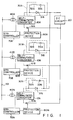
- Fig. 1 illustrates a power converting apparatus according to the first embodiment of the present invention.
- the power converting apparatus includes a plurality of self-commutated converters 10A to 10N.
- the DC terminals of the self-commutated converters 10A to 10N are connected to a common DC circuit 20, while the AC terminals are connected to an AC power system 50 respectively through transformers 40A to 40N.
- the self-commutated converters 10A to 10N are designed the same as the self-commutated converter shown in Fig. 6.
- Fault current restricting devices 30A to 30N are inserted between the individual self-commutated converters 10A to 10N and the DC circuit 20, respectively.
- the fault current restricting device 30A comprises a diode 31A to be inserted between the self-commutated converter 10A and the DC circuit 20 in the direction to allow the current from the converter 10A to flow to the DC circuit 20, and a series circuit including a reactor 32A and a DC power supply 33A and connected in parallel to the diode 31A.
- the other fault current restricting devices 30B to 30N are designed the same as the fault current restricting device 30A.
- Protection devices 60A to 60N and GTO controller 70A to 70N are provided in the respective self-commutated converters 10A to 10N.
- the DC circuit currents flowing in the self-commutated converters 10A to 10N are detected by current detectors 61A to 61N provided for the respective self-commutated converters 10A to 10N.
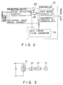
- Fig. 2 illustrates the structure of the protection device 60A and GTO controller 70A.
- the protection device 60A supplies a current detect signal indicating the detected current of the self-commutated converter 10A to a level detecting circuit 62.
- the level detecting circuit 62 compares the value of the current detect signal with a reference value corresponding to the rated current for the self-commutated converter 10A. When the value of the current detect signal exceeds the reference value, the level detecting circuit 62 supplies a fault detect signal to an OR circuit 63.
- the protection device 60A uses an off-gate circuit 71 in the controller 70A to provide a gate disable signal to the GTO.
- the controller 70A comprises the off-gate circuit 71, a gate timing pulse generator 72, and an on-gate circuit 73.
- the gate timing pulse generator 72 sends a gate enable command and a gate disable command in accordance with the specified value of the DC circuit current, the specified power value, and so forth for the self-commutated converter 10A.
- the off-gate circuit 71 sends a gate disable signal to the GTO in response to the gate disable command.
- the on-gate circuit 73 sends a gate enable signal to the GTO in response to the gate enable command.
- Fig. 3 shows the structure of the DC circuit 20, which has an AC power supply 21 connected to a semiconductor rectifier 24 through a circuit breaker 22 and a transformer 23.
- the voltage of the DC power supply 33A is controlled so that a circulating current Ib flowing through a closed circuit from the DC power supply 33A, to the reactor 32A, to the diode 31A, back to the DC power supply 33A is slightly greater than the rated current Ido.
- the other fault current restricting devices 30B through 30N are also true.
- the self-commutated converters 10A to 10N are currently in forward conversion mode to convert AC power from the AC power system 50 into DC power.
- the DC circuit current Id in the self-commutated converters 10A to 10N becomes smaller than the rated current Ido, and the current flowing in each of the diodes 31A to 31N of the respective fault current restricting devices 30A to 30N becomes almost equal to (circulating current Ib + DC circuit current Id).
- the fault current tends to flow from other properly operating self-commutated converters and the DC circuit 20 toward the short-circuited self-commutated converter.
- This fault current is significantly greater than the rated current Ido.
- the fault current tends to flow, in the reverse direction, across the diode in the fault current restricting device corresponding to the malfunctioning self-commutated converter.
- the diode how-ever blocks the current flow in the reverse direction.
- the fault current then flows to the reactor connected in parallel to the diode. Since the reactor originally serves to suppress the current, the current-increase factor of the fault current, di/dt, is suppressed.
- the protection device 60 generates a fault detect signal when the DC short circuit occurs, and sends this signal as the gate disable signal via the OR circuit 63 to the off-gate circuit 71.
- the off-gate circuit 71 sends the gate disable signal to the other properly operating GTOs, cutting off the fault current.
- the value of the fault current is small enough when the protection device 60 sends the gate disable signal to the GTOs, so that the GTOs will not be damaged.
- a constant current flows to the reactor in the fault current restricting device in the normal operation, while the reactor prevents an increase in the fault current when some self-commutated converter malfunctions. It is therefore possible to suppress the increase factor of the fault current without impairing the transient response of the self-commutated converter.
- the suppression on the increase factor of the fault current saves enough time to turn off the properly functioning GTOs. Accordingly, the fault current can be cut off without damaging the GTOs.
- fuses for protecting against overcurrent need not be used, and the power converting apparatus of the present invention is therefore applicable to a wide variety of voltage circuits from a low-voltage circuit involving a voltage of 1 kV or less to a high-voltage circuit involving a voltage of over 10 kV.
- Fig. 4 illustrates the functional blocks of a power converting apparatus according to this embodiment.
- the second embodiment is the first embodiment whose fault current restricting device is modified.
- Fault current restricting devices 80A and 80B in this embodiment respectively comprise thyristor rectifiers 34A and 34B as DC power supplies, auxiliary power supplies 35A and 35B, transformers 36A and 36B, current detectors 37A and 37B, current detectors 38A and 38B, and circulating current controllers 39A and 39B.
- the transformers 36A and 36B transform voltages from the auxiliary power supplies 35A and 35B and apply them to the thyristor rectifiers 34A and 34B, respectively.
- the current detectors 37A and 37B respectively detect the DC circuit currents in the self-commutated converters 10A and 10B.
- the current detectors 38A and 38B detect the circulating current.
- the circulating current controllers 39A and 39B receive the detected values of the DC circuit current and the circulating current, and control the firing angles for the thyristor rectifiers 34A and 34B.
- Fig. 5 illustrates the structure of the circulating current controller 39A or 39B.
- the direction of the DC circuit current Id in the self-commutated converter 10A or 10B is considered to be forward in the reverse conversion, so that the DC circuit current is treated to have a negative value in the forward conversion.
- a limiter 81 receives the detect signal from the associated current detector 37A or 37B indicating the DC circuit current Id.
- Each limiter 81 also receives a mode setting signal indicating the conversion mode of the associated self-commutated converter, and changes its limit value between in the forward conversion and in the reverse conversion.
- the limiter 81 sets the limit value to "0" in the forward conversion, while setting the limit value to the rated current Ido in the reverse conversion.
- the limiter 81 outputs the value of the signal as the specified value of the circulating current.
- the limiter 81 holds the specified value of the circulating current at the limit value.
- the specified circulating current value can be held at "0" in the forward conversion.
- the specified circulating current value is held at the value of the rated current Ido even though the fault current increases the value of the current.
- a subtractor 82 performs subtraction on the specified circulating current value from the limiter 81 and the detect signal of the circulating current Ib detected by the associated current detector 38A or 38B, and sends the resultant value to a current controller 83.
- the current controller 83 outputs a control signal in accordance with the received value, i.e., the difference between the specified value and the actually detected value of the circulating current.
- a phase control circuit 84 outputs a firing pulse of the associated thyristor rectifier 34A or 34B in accordance with the control signal sent from the current controller 83.
- the specified circulating current value or the output of the limiter 81 is limited to zero in the forward conversion and is limited to equal to or below the rated current Ido in the reverse conversion in accordance with the DC circuit current value Id in the associated self-commutated converter 10A or 10B.
- the circulating current Ib is subjected to constant-current control by the subtractor 82, current controller 83 and phase control circuit 84 to have a value equal to the specified circulating current value.
- the circulating current Ib becomes zero in the forward conversion and becomes equal to the rated current Ido in the reverse conversion.
- the limiter 81 functions to limit the circulating current Ib to the limit value.
- the fault current flowing through the reactor 32A or 32B is considered as the circulating current and is to be limited to the rated current Ido. The effect of suppressing the current-increase factor of the fault current is therefore further enhanced as compared with the case involving only the reactor.
- the circulating current follows up the DC circuit current of the self-commutated converters as well as the effect of suppressing the fault current is improved. It is therefore possible to prevent the unnecessary current from flowing through the self-commutated converters, thus reducing the power loss as much as possible.
- a self-commutated converter is provided for each fault current restricting device in the first and second embodiments, a plurality of self-commutated converters may share a single fault current restricting device.
- individual self-commutated converters each have one end connected to one terminal of a common DC circuit and the other terminal connected the anode terminal of the diode in a single fault current restricting device, with the other terminal of the DC circuit connected to the cathode terminal of the fault current restricting device.
- a value obtained by converting the specified value of the DC circuit current in the self-commutated converter or the specified power value may be used as the specified value of the circulating current.
- the present invention may be applied to a power converting apparatus which comprises self-commutated converters designed to perform only the forward conversion or reverse conversion.
Landscapes
- Engineering & Computer Science (AREA)
- Power Engineering (AREA)
- Rectifiers (AREA)
- Protection Of Static Devices (AREA)
Description
- The present invention relates to a power converting apparatus comprising a single or a plurality of self-commutated power converters (hereafter referred to as "self-commutated converters") in common with a DC circuit, using a self turn-off type semiconductor device (hereafter referred to as "self turn-off device"). More particularly, the present invention pertains to a power converting apparatus which can suppress a fault current which occurs when DC short circuit occurs in any self-commutated converter.
- There are various methods to interrupting the current caused by when a DC short circuit occurs in a self-commutated converter.
- The first method is to use fuses. According to this method, a fuse is inserted in series with each self turn-off device into the circuit of the self-commutated converter comprising multiple self turn-off devices to thereby cut off the fault current by the fuse when melted.
- As the second method, the self turn-off function (current interrupting function) of the self turn-off device is utilized to cut off the fault current.
- Fig. 6 illustrates the arrangement of the self-commutated converter using a gate turn off thyristor (GTO) as its self turn-off device.
- A self-commutated
converter 10 comprises GTOs 11U to 11Z anddiodes 12U to 12Z which are connected in parallel in the reverse direction to the respective GTOs. The DC terminal of the self-commutatedconverter 10 is connected to aDC circuit 20, while the AC terminal is connected to anAC system 50 through atransformer 40. - Suppose that the GTO 11X is short-circuited due to some reason while the GTO 11U is conductive. Then, an excessive fault current flows to the
GTOs 11U and 11X to cause a DC short circuit. A protection device (not shown) detects the fault current which flows through theGTOs 11U and 11X, and provides a gate disable signal to the GTO 11U which is normally activated. As a result, the fault current which tends to flow between theGTOs 11U and 11X is cut off by the GTO 11U, thus protecting the self-commutatedconverter 10. - The first method is available for a low-voltage circuit involving a DC voltage of 1 kV or lower; however, when the circuit voltage rises above the level, this method is not applicable because of no fuses available for such a high voltage.
- In the second method, the current-increase factor di/dt of the fault current is very large. When the protection device detects the fault current, then provides the gate disable signal to the GTO, therefore, the value of the current flowing in the GTO is already beyond the value where the GTO can be rendered off. If the GTO is forced to be turned off under such conditions, the GTO itself may be damaged, amplifying the fault.
- Prior art document US-A-4 488 200 discloses a no-break power supply apparatus including a plurality of constant-voltage constant-frequency power supplies (CVCFs), each CVCF having a bridge circuit having an arm including inverters, a parallel circuit having the GTO thyristor and a diode connected in reverse polarity in parallel with the GTO thyristor. A fuse is connected in series with the parallel circuit, and a fuse melting detector is connected across the fuse. A protecting circuit is controlled for supplying a predetermined ON gate signal/OFF gate signal in accordance with the fuse melting detection signal detected when an accident occurs to the gate of each GTO thyristor.
- It is an object of the present invention to provide a power converting apparatus which can suppress the current-increase factor di/dt of a fault current without deteriorating a transient response in normal operation, and can cut off the fault current without damaging a self turn-off device. It is another object of the present invention to provide a power converting apparatus which can cut off a fault current without using any fuse, and is applicable to circuits from a low-voltage circuit to a high-voltage one.
- To solve this object the present invention provides a power converting apparatus as specified in
claim 1. - A power converting apparatus according to the present invention comprises self-commutated converter for converting AC power supplied from an AC power system into DC power and supplying the DC power to a DC circuit, and for converting DC power supplied from the DC circuit into AC power and supplying the AC power to the AC power system; fault current restricting device connected between the self-commutated converter and the DC circuit and including a diode for permitting a DC circuit current to flow from the self-commutated converter to the DC circuit, and a series circuit having a reactor and a DC power supply and connected in parallel to the diode; and a protection device for detecting the DC circuit current in the self-commutated converter and controlling activation of the self-commutated converter in accordance with a value of the detected DC circuit current, whereby the DC power supply supplies a circulating current according to a rated current of the self-commutated converter to the reactor and the diode.
- According to the above-structured power converting apparatus of the present invention, when a DC short circuit occurs in the self-commutated converter, the diode blocks a fault current, which then flows through the reactor into the self-commutated converter. Since the reactor serves to control the current-increase factor of the fault current, it takes some time for the value of the fault current flowing in the self-commutated converter to reach the level beyond which the self turn-off device can no longer shield the current after the occurrence of the fault. It is not therefore late to send a gate disable signal to the self turn-off device, even after the protection device detects the fault current, to cut off the fault current in the self-commutated converter, thus preventing the self-commutated converter from malfunctioning.
- This invention can be more fully understood from the following detailed description when taken in conjunction with the accompanying drawings, in which:
- Fig. 1 is a block diagram of a power converting apparatus according to the first embodiment of the present invention;
- Fig. 2 is a diagram illustrating the structure of a protection device;
- Fig. 3 is a diagram showing the structure of a DC circuit;
- Fig. 4 is a block diagram of a power converting apparatus according to the second embodiment of the present invention;
- Fig. 5 is a diagram illustrating the structure of a circulating current controller; and
- Fig. 6 is a diagram showing the structure of a self-commutated converter.
- Preferred embodiments of the present invention will now be described referring to the accompanying drawings.
- Fig. 1 illustrates a power converting apparatus according to the first embodiment of the present invention. The power converting apparatus includes a plurality of self-commutated converters 10A to 10N. The DC terminals of the self-commutated converters 10A to 10N are connected to a
common DC circuit 20, while the AC terminals are connected to anAC power system 50 respectively throughtransformers 40A to 40N. The self-commutated converters 10A to 10N are designed the same as the self-commutated converter shown in Fig. 6. - Fault
current restricting devices 30A to 30N are inserted between the individual self-commutated converters 10A to 10N and theDC circuit 20, respectively. - The fault
current restricting device 30A comprises adiode 31A to be inserted between the self-commutated converter 10A and theDC circuit 20 in the direction to allow the current from the converter 10A to flow to theDC circuit 20, and a series circuit including areactor 32A and aDC power supply 33A and connected in parallel to thediode 31A. - The other fault
current restricting devices 30B to 30N are designed the same as the faultcurrent restricting device 30A. -
Protection devices 60A to 60N andGTO controller 70A to 70N are provided in the respective self-commutated converters 10A to 10N. The DC circuit currents flowing in the self-commutated converters 10A to 10N are detected by current detectors 61A to 61N provided for the respective self-commutated converters 10A to 10N. - Fig. 2 illustrates the structure of the
protection device 60A andGTO controller 70A. - The
protection device 60A supplies a current detect signal indicating the detected current of the self-commutated converter 10A to alevel detecting circuit 62. Thelevel detecting circuit 62 compares the value of the current detect signal with a reference value corresponding to the rated current for the self-commutated converter 10A. When the value of the current detect signal exceeds the reference value, thelevel detecting circuit 62 supplies a fault detect signal to anOR circuit 63. - The
protection device 60A uses an off-gatecircuit 71 in thecontroller 70A to provide a gate disable signal to the GTO. Thecontroller 70A comprises the off-gatecircuit 71, a gatetiming pulse generator 72, and an on-gate circuit 73. The gatetiming pulse generator 72 sends a gate enable command and a gate disable command in accordance with the specified value of the DC circuit current, the specified power value, and so forth for the self-commutated converter 10A. The off-gatecircuit 71 sends a gate disable signal to the GTO in response to the gate disable command. The on-gate circuit 73 sends a gate enable signal to the GTO in response to the gate enable command. - Fig. 3 shows the structure of the
DC circuit 20, which has anAC power supply 21 connected to asemiconductor rectifier 24 through acircuit breaker 22 and atransformer 23. - The operation of this embodiment with above-described structure will now be explained.
- According to this embodiment, provided that the self-commutated converters 10A to 10N have the same capacity, and their rated current is set Ido, the voltage of the
DC power supply 33A is controlled so that a circulating current Ib flowing through a closed circuit from theDC power supply 33A, to thereactor 32A, to thediode 31A, back to theDC power supply 33A is slightly greater than the rated current Ido. The same is true of the other faultcurrent restricting devices 30B through 30N. - Suppose that the self-commutated converters 10A to 10N are currently in forward conversion mode to convert AC power from the
AC power system 50 into DC power. When the self-commutated converters 10A to 10N are functioning normally, the DC circuit current Id in the self-commutated converters 10A to 10N becomes smaller than the rated current Ido, and the current flowing in each of thediodes 31A to 31N of the respective faultcurrent restricting devices 30A to 30N becomes almost equal to (circulating current Ib + DC circuit current Id). - When the self-commutated converters 10A to 10N are in reverse conversion mode to convert the DC power from the
DC circuit 20 into the AC power, the current flowing across each of thediodes 31A to 31N is almost equal to (circulating current Ib - DC circuit current Id). - If a DC short circuit occurs in any of the self-commutated converters 10A to 10N under the above operating conditions, the fault current tends to flow from other properly operating self-commutated converters and the
DC circuit 20 toward the short-circuited self-commutated converter. This fault current is significantly greater than the rated current Ido. The fault current tends to flow, in the reverse direction, across the diode in the fault current restricting device corresponding to the malfunctioning self-commutated converter. The diode how-ever blocks the current flow in the reverse direction. The fault current then flows to the reactor connected in parallel to the diode. Since the reactor originally serves to suppress the current, the current-increase factor of the fault current, di/dt, is suppressed. - The
protection device 60 generates a fault detect signal when the DC short circuit occurs, and sends this signal as the gate disable signal via theOR circuit 63 to theoff-gate circuit 71. As a result, theoff-gate circuit 71 sends the gate disable signal to the other properly operating GTOs, cutting off the fault current. - As the reactor has suppressed the current-increase factor of the fault current, di/dt, the value of the fault current is small enough when the
protection device 60 sends the gate disable signal to the GTOs, so that the GTOs will not be damaged. - Since the DC circuit current flows not through the reactor in the steady operation, preventing the transient response of the self-commutated converters from being deteriorated.
- According to this embodiment as described above, a constant current flows to the reactor in the fault current restricting device in the normal operation, while the reactor prevents an increase in the fault current when some self-commutated converter malfunctions. It is therefore possible to suppress the increase factor of the fault current without impairing the transient response of the self-commutated converter.
- The suppression on the increase factor of the fault current saves enough time to turn off the properly functioning GTOs. Accordingly, the fault current can be cut off without damaging the GTOs.
- Further, fuses for protecting against overcurrent need not be used, and the power converting apparatus of the present invention is therefore applicable to a wide variety of voltage circuits from a low-voltage circuit involving a voltage of 1 kV or less to a high-voltage circuit involving a voltage of over 10 kV.
- The second embodiment of the present invention will now be described.
- Fig. 4 illustrates the functional blocks of a power converting apparatus according to this embodiment.
- The second embodiment is the first embodiment whose fault current restricting device is modified.
- Fault current restricting
devices thyristor rectifiers auxiliary power supplies transformers current detectors current detectors current controllers 39A and 39B. Thetransformers auxiliary power supplies thyristor rectifiers current detectors converters 10A and 10B. Thecurrent detectors current controllers 39A and 39B receive the detected values of the DC circuit current and the circulating current, and control the firing angles for thethyristor rectifiers - Fig. 5 illustrates the structure of the circulating
current controller 39A or 39B. - It is to be noted that the direction of the DC circuit current Id in the self-commutated
converter 10A or 10B is considered to be forward in the reverse conversion, so that the DC circuit current is treated to have a negative value in the forward conversion. - In each of the circulating
current controllers 39A and 39B, alimiter 81 receives the detect signal from the associatedcurrent detector limiter 81 also receives a mode setting signal indicating the conversion mode of the associated self-commutated converter, and changes its limit value between in the forward conversion and in the reverse conversion. Thelimiter 81 sets the limit value to "0" in the forward conversion, while setting the limit value to the rated current Ido in the reverse conversion. As far as the received detect signal of the DC circuit current Id has a value below the limit, thelimiter 81 outputs the value of the signal as the specified value of the circulating current. When the DC circuit current Id reaches the limit, thelimiter 81 holds the specified value of the circulating current at the limit value. - In other words, even if the value of the current increases by the fault current, the specified circulating current value can be held at "0" in the forward conversion. In the reverse conversion, the specified circulating current value is held at the value of the rated current Ido even though the fault current increases the value of the current.
- A
subtractor 82 performs subtraction on the specified circulating current value from thelimiter 81 and the detect signal of the circulating current Ib detected by the associatedcurrent detector current controller 83. Thecurrent controller 83 outputs a control signal in accordance with the received value, i.e., the difference between the specified value and the actually detected value of the circulating current. Aphase control circuit 84 outputs a firing pulse of the associatedthyristor rectifier current controller 83. - The operation of the second embodiment having the above-described arrangement will be described below.
- In the individual fault current restricting
devices limiter 81 is limited to zero in the forward conversion and is limited to equal to or below the rated current Ido in the reverse conversion in accordance with the DC circuit current value Id in the associated self-commutatedconverter 10A or 10B. The circulating current Ib is subjected to constant-current control by thesubtractor 82,current controller 83 andphase control circuit 84 to have a value equal to the specified circulating current value. - In other words, the circulating current Ib becomes zero in the forward conversion and becomes equal to the rated current Ido in the reverse conversion.
- When a DC short circuit occurs in either the self-commutated
converter 10A or 10B and the DC circuit current Id in that short-circuited converter increases, thelimiter 81 functions to limit the circulating current Ib to the limit value. In particular, when the short circuit occurs in the reverse conversion, the fault current flowing through thereactor - As this embodiment works as described above, the circulating current follows up the DC circuit current of the self-commutated converters as well as the effect of suppressing the fault current is improved. It is therefore possible to prevent the unnecessary current from flowing through the self-commutated converters, thus reducing the power loss as much as possible.
- While a self-commutated converter is provided for each fault current restricting device in the first and second embodiments, a plurality of self-commutated converters may share a single fault current restricting device.
- More specifically, individual self-commutated converters each have one end connected to one terminal of a common DC circuit and the other terminal connected the anode terminal of the diode in a single fault current restricting device, with the other terminal of the DC circuit connected to the cathode terminal of the fault current restricting device.
- A value obtained by converting the specified value of the DC circuit current in the self-commutated converter or the specified power value may be used as the specified value of the circulating current.
- While the self-commutated converters in the first and second embodiments are designed to be able to selectively perform the forward conversion and the reverse conversion, the present invention may be applied to a power converting apparatus which comprises self-commutated converters designed to perform only the forward conversion or reverse conversion.
- In addition, while the individual embodiments have been described as having a plurality of self-commutated converters, the present invention can also be applied to a power converting apparatus comprising a single self-commutated converter.
Claims (9)
- A power converting apparatus comprising:
self-commutated converter means (10) having DC terminal connected to a DC circuit (20) for performing at least one of a conversion of DC power to AC power and a conversion of the AC power to the DC power;
characterized by further comprising
fault current restricting means (30), inserted between said self-commutated converter means (10) and said DC circuit (20) and including a unidirectional rectifying element (31) for permitting a DC circuit current to flow from said self-commutated converter means (10) to said DC circuit (20), and a series circuit having a reactor (32) and a DC power supply (33) and connected in parallel to said rectifying element (31); and
protection means (60) for detecting said DC circuit current in said self-commutated converter means (10) and controlling said self-commutated converter means (10) in accordance with a value of said detected DC circuit current to prevent an excess current from flowing through said self-commutated converter means (10), whereby said DC power supply (33) supplies a circulating current according to a rated current for said self-commutated converter means (10) to said reactor (32) and said rectifying element (31). - A power converting apparatus according to claim 1, characterized in that said fault current restricting means (30) further includes constant-current control means (37 to 39) for holding said circulating current to a predetermined current value.
- A power converting apparatus according to claim 2, characterized in that said DC power supply (33) includes a thyristor rectifier(34); and
said constant-current control means (37 to 39) includes:
DC circuit current detecting means (37) for detecting a DC circuit current in said self-commutated converter means (10);
circulating current detecting means (38) for detecting said circulating current flowing through said reactor (32); and
circulating current control means (39) for generating a firing signal to control a firing angle of the thyristor rectifier (34) in accordance with a value of the DC circuit current detected by said DC circuit current detecting means (37) and a value of said circulating current detected by said circulating current detecting means (38). - A power converting apparatus according to claim 3, characterized in that said circulating current control means (38) includes:
limiter (81) receiving the DC circuit current from said DC circuit current detecting means (37) for outputting a value of a DC circuit current as a specified circulating current value, limiting said circulating current value in close proximity to zero at a time of an AC-to-DC conversion, and limiting said circulating current value in close proximity to a value of said rated current at a time of a DC-to-AC conversion, when said DC circuit current in said DC-to-AC conversion flows in a direction from said DC circuit (20) toward said self-commutated converter means (10);
subtractor (82) for calculating a difference between said specified circulating current value from said limiter (81) and said circulating current value detected by said circulating current detecting means (38); and
phase controller (84) for controlling said firing angle of said thyristor rectifier (34) in accordance with said difference output from said subtractor (82). - A power converting apparatus according to claim 1, characterized in that said protection means (60) includes:
current detecting means (61) for detecting said DC circuit current in said self-commutated converter means (10);
a comparator (62) for comparing a value of said DC circuit current detected by said current detecting means (61) with a reference value and outputting a fault detect signal when said DC circuit current value exceeds said reference value; and
cutoff means (70) for cutting off power supply to said self-commutated converter means (10) when said fault detect signal is output. - A power converting apparatus according to claim 1, characterized in that said unidirectional rectifying element (31) includes a diode.
- A power converting apparatus according to any one of claims 1 to 6, characterized in that said self-commutated converter means (10) comprises a plurality of self-commutated converters (10A to 10N), each performing at least one of the DC-to-AC conversion and the AC-to-DC conversion.
- A power converting apparatus according to claim 7, characterized in that said fault current restricting means (30) is provided for each of said self-commutated converters (10A to 10N).
- A power converting apparatus according to any one of claims 1 to 6, characterized in that said self-commutated converter means (10) comprises a single self-commutated converter for performing at least one of the DC-to-AC conversion and the AC-to-DC conversion.
Applications Claiming Priority (2)
| Application Number | Priority Date | Filing Date | Title |
|---|---|---|---|
| JP2206715A JPH0491659A (en) | 1990-08-06 | 1990-08-06 | Power supply conversion device |
| JP206715/90 | 1990-08-06 |
Publications (3)
| Publication Number | Publication Date |
|---|---|
| EP0470525A2 EP0470525A2 (en) | 1992-02-12 |
| EP0470525A3 EP0470525A3 (en) | 1992-05-06 |
| EP0470525B1 true EP0470525B1 (en) | 1994-08-10 |
Family
ID=16527913
Family Applications (1)
| Application Number | Title | Priority Date | Filing Date |
|---|---|---|---|
| EP91113055A Expired - Lifetime EP0470525B1 (en) | 1990-08-06 | 1991-08-02 | Power converter with shoot-through protection |
Country Status (5)
| Country | Link |
|---|---|
| US (1) | US5179510A (en) |
| EP (1) | EP0470525B1 (en) |
| JP (1) | JPH0491659A (en) |
| CA (1) | CA2048370C (en) |
| DE (1) | DE69103358T2 (en) |
Families Citing this family (13)
| Publication number | Priority date | Publication date | Assignee | Title |
|---|---|---|---|---|
| US5309346A (en) * | 1991-09-16 | 1994-05-03 | Westinghouse Electric Corp. | Transmission line fault current dynamic inverter control |
| JP3437685B2 (en) * | 1995-09-12 | 2003-08-18 | 株式会社東芝 | Control and protection system for AC / DC converter |
| JPH10127065A (en) * | 1996-10-18 | 1998-05-15 | Tokyo Electric Power Co Inc:The | Power converter |
| US5894415A (en) * | 1997-12-05 | 1999-04-13 | Lucent Technologies, Inc. | Fault tolerant power supply including a switching mechanism for controlling the operation of plural voltage converters in response to changing input voltage levels |
| US5986909A (en) * | 1998-05-21 | 1999-11-16 | Robicon Corporation | Multiphase power supply with plural series connected cells and failed cell bypass |
| US6087738A (en) * | 1998-08-20 | 2000-07-11 | Robicon Corporation | Variable output three-phase transformer |
| US6262555B1 (en) | 1998-10-02 | 2001-07-17 | Robicon Corporation | Apparatus and method to generate braking torque in an AC drive |
| US6278624B1 (en) * | 1999-12-01 | 2001-08-21 | Hewlett-Packard Company | High availability DC power supply with isolated inputs, diode-or-connected outputs, and power factor correction |
| US6741482B2 (en) * | 2001-09-14 | 2004-05-25 | Kabushiki Kaisha Toshiba | Power conversion device |
| WO2012119645A1 (en) * | 2011-03-08 | 2012-09-13 | Siemens Aktiengesellschaft | System for transmitting electrical power from a direct current line to an alternating voltage network |
| US9912151B2 (en) | 2015-01-23 | 2018-03-06 | General Electric Company | Direct current power system |
| CN105730248B (en) * | 2016-03-03 | 2017-10-13 | 南京南瑞继保电气有限公司 | A kind of locomotive regenerative electric energy feedback system and control method for having ice-melt function concurrently |
| US11770066B2 (en) | 2021-06-11 | 2023-09-26 | Hamilton Sundstrand Corporation | Protection circuitry for power converters |
Family Cites Families (8)
| Publication number | Priority date | Publication date | Assignee | Title |
|---|---|---|---|---|
| US3798530A (en) * | 1972-10-17 | 1974-03-19 | Gould Inc | Static switch circuit |
| US3832573A (en) * | 1973-02-15 | 1974-08-27 | Megapulse Inc | Over-current latch-up protection apparatus for scr inverter circuits and the like |
| US4220989A (en) * | 1978-12-08 | 1980-09-02 | Perilstein Fred M | Polyphase variable frequency inverter with output voltage control |
| US4488200A (en) * | 1982-09-23 | 1984-12-11 | Tokyo Shibaura Denki Kabushiki Kaisha | No-break power supply apparatus |
| JPS5963983A (en) * | 1982-10-04 | 1984-04-11 | Hitachi Ltd | Controller for power converter |
| US4720776A (en) * | 1984-12-04 | 1988-01-19 | Square D Company | DC bus shorting apparatus and method for polyphase AC inverter |
| US4805082A (en) * | 1988-03-14 | 1989-02-14 | Westinghouse Electric Corp. | Regenerative two-quadrant converter |
| FR2645369A1 (en) * | 1989-03-30 | 1990-10-05 | Alcatel Espace | POWER MODULE FOR CONTINUOUS MOTOR CONTROL ELECTRONICS |
-
1990
- 1990-08-06 JP JP2206715A patent/JPH0491659A/en active Pending
-
1991
- 1991-08-02 CA CA002048370A patent/CA2048370C/en not_active Expired - Fee Related
- 1991-08-02 EP EP91113055A patent/EP0470525B1/en not_active Expired - Lifetime
- 1991-08-02 DE DE69103358T patent/DE69103358T2/en not_active Expired - Fee Related
- 1991-08-06 US US07/741,073 patent/US5179510A/en not_active Expired - Fee Related
Also Published As
| Publication number | Publication date |
|---|---|
| JPH0491659A (en) | 1992-03-25 |
| EP0470525A3 (en) | 1992-05-06 |
| EP0470525A2 (en) | 1992-02-12 |
| CA2048370A1 (en) | 1992-02-07 |
| CA2048370C (en) | 1995-12-12 |
| DE69103358T2 (en) | 1994-12-01 |
| US5179510A (en) | 1993-01-12 |
| DE69103358D1 (en) | 1994-09-15 |
Similar Documents
| Publication | Publication Date | Title |
|---|---|---|
| EP3706276B1 (en) | Bypass thyristor valve group inspection method and control device | |
| US11139808B2 (en) | Semiconductor device and power conversion system | |
| US5617012A (en) | Power converter protecting apparatus for electric power system | |
| KR940002919B1 (en) | Control device of power converter | |
| EP0470525B1 (en) | Power converter with shoot-through protection | |
| US20200366186A1 (en) | Modular multilevel converter sub-module having dc fault current blocking function and method of controlling the same | |
| US4745513A (en) | Protection of GTO converters by emitter switching | |
| JPWO2018211658A1 (en) | Reactive power compensation device and control method thereof | |
| EP0538825A2 (en) | Power converting apparatus | |
| US3424948A (en) | Overvoltage protection circuit for controlled solid state valves | |
| JP3160414B2 (en) | Conversion device | |
| JP3321298B2 (en) | Fault detection circuit of voltage type self-excited converter | |
| JP7086298B2 (en) | Power converter | |
| US11258247B2 (en) | Fault clearing circuitry | |
| JP2005192354A (en) | Alternating-current switch device and power supply device using the same | |
| JPH0821861A (en) | Power converter failure detection circuit | |
| JP4528552B2 (en) | Excitation control device for synchronous machine | |
| JP2998213B2 (en) | How to operate the power supply | |
| JP2002525001A (en) | electric circuit | |
| JP3971089B2 (en) | Current limiting device | |
| JPH07177743A (en) | Controller of AC / DC converter | |
| JP2002112452A (en) | Power converter | |
| JP3585792B2 (en) | Power converter | |
| JPH0847182A (en) | Power supply switching circuit for uninterruptible power supply | |
| JPS62100163A (en) | Gate turn-off thyristor protection device |
Legal Events
| Date | Code | Title | Description |
|---|---|---|---|
| PUAI | Public reference made under article 153(3) epc to a published international application that has entered the european phase |
Free format text: ORIGINAL CODE: 0009012 |
|
| 17P | Request for examination filed |
Effective date: 19910830 |
|
| AK | Designated contracting states |
Kind code of ref document: A2 Designated state(s): DE FR GB SE |
|
| PUAL | Search report despatched |
Free format text: ORIGINAL CODE: 0009013 |
|
| AK | Designated contracting states |
Kind code of ref document: A3 Designated state(s): DE FR GB SE |
|
| 17Q | First examination report despatched |
Effective date: 19930629 |
|
| GRAA | (expected) grant |
Free format text: ORIGINAL CODE: 0009210 |
|
| AK | Designated contracting states |
Kind code of ref document: B1 Designated state(s): DE FR GB SE |
|
| REF | Corresponds to: |
Ref document number: 69103358 Country of ref document: DE Date of ref document: 19940915 |
|
| ET | Fr: translation filed | ||
| EAL | Se: european patent in force in sweden |
Ref document number: 91113055.7 |
|
| PLBE | No opposition filed within time limit |
Free format text: ORIGINAL CODE: 0009261 |
|
| STAA | Information on the status of an ep patent application or granted ep patent |
Free format text: STATUS: NO OPPOSITION FILED WITHIN TIME LIMIT |
|
| 26N | No opposition filed | ||
| PGFP | Annual fee paid to national office [announced via postgrant information from national office to epo] |
Ref country code: FR Payment date: 19980717 Year of fee payment: 8 |
|
| PGFP | Annual fee paid to national office [announced via postgrant information from national office to epo] |
Ref country code: GB Payment date: 19980724 Year of fee payment: 8 |
|
| PGFP | Annual fee paid to national office [announced via postgrant information from national office to epo] |
Ref country code: DE Payment date: 19981029 Year of fee payment: 8 |
|
| PG25 | Lapsed in a contracting state [announced via postgrant information from national office to epo] |
Ref country code: GB Free format text: LAPSE BECAUSE OF NON-PAYMENT OF DUE FEES Effective date: 19990802 |
|
| GBPC | Gb: european patent ceased through non-payment of renewal fee |
Effective date: 19990802 |
|
| PG25 | Lapsed in a contracting state [announced via postgrant information from national office to epo] |
Ref country code: FR Free format text: LAPSE BECAUSE OF NON-PAYMENT OF DUE FEES Effective date: 20000428 |
|
| PG25 | Lapsed in a contracting state [announced via postgrant information from national office to epo] |
Ref country code: DE Free format text: LAPSE BECAUSE OF NON-PAYMENT OF DUE FEES Effective date: 20000601 |
|
| REG | Reference to a national code |
Ref country code: FR Ref legal event code: ST |
|
| PGFP | Annual fee paid to national office [announced via postgrant information from national office to epo] |
Ref country code: SE Payment date: 20000816 Year of fee payment: 10 |
|
| PG25 | Lapsed in a contracting state [announced via postgrant information from national office to epo] |
Ref country code: SE Free format text: LAPSE BECAUSE OF NON-PAYMENT OF DUE FEES Effective date: 20010803 |
|
| EUG | Se: european patent has lapsed |
Ref document number: 91113055.7 |