EP0470497B1 - Optical fiber amplifier - Google Patents
Optical fiber amplifier Download PDFInfo
- Publication number
- EP0470497B1 EP0470497B1 EP91112890A EP91112890A EP0470497B1 EP 0470497 B1 EP0470497 B1 EP 0470497B1 EP 91112890 A EP91112890 A EP 91112890A EP 91112890 A EP91112890 A EP 91112890A EP 0470497 B1 EP0470497 B1 EP 0470497B1
- Authority
- EP
- European Patent Office
- Prior art keywords
- optical fiber
- light
- wavelength
- doped
- signal light
- Prior art date
- Legal status (The legal status is an assumption and is not a legal conclusion. Google has not performed a legal analysis and makes no representation as to the accuracy of the status listed.)
- Expired - Lifetime
Links
Images


Classifications
-
- H—ELECTRICITY
- H01—ELECTRIC ELEMENTS
- H01S—DEVICES USING THE PROCESS OF LIGHT AMPLIFICATION BY STIMULATED EMISSION OF RADIATION [LASER] TO AMPLIFY OR GENERATE LIGHT; DEVICES USING STIMULATED EMISSION OF ELECTROMAGNETIC RADIATION IN WAVE RANGES OTHER THAN OPTICAL
- H01S3/00—Lasers, i.e. devices using stimulated emission of electromagnetic radiation in the infrared, visible or ultraviolet wave range
- H01S3/05—Construction or shape of optical resonators; Accommodation of active medium therein; Shape of active medium
- H01S3/06—Construction or shape of active medium
- H01S3/063—Waveguide lasers, i.e. whereby the dimensions of the waveguide are of the order of the light wavelength
- H01S3/067—Fibre lasers
- H01S3/06754—Fibre amplifiers
- H01S3/06758—Tandem amplifiers
-
- H—ELECTRICITY
- H01—ELECTRIC ELEMENTS
- H01S—DEVICES USING THE PROCESS OF LIGHT AMPLIFICATION BY STIMULATED EMISSION OF RADIATION [LASER] TO AMPLIFY OR GENERATE LIGHT; DEVICES USING STIMULATED EMISSION OF ELECTROMAGNETIC RADIATION IN WAVE RANGES OTHER THAN OPTICAL
- H01S2301/00—Functional characteristics
- H01S2301/02—ASE (amplified spontaneous emission), noise; Reduction thereof
Definitions
- the present invention relates to an optical fiber suitable for use in an optical fiber amplifier for directly amplifying signal light.
- an optical fiber amplifier with a high gain 2-stage amplification stage is disclosed.
- This optical fiber amplifier employs for the 2-stage construction optical fibers, which are doped with erbium for amplifying signal light inputted into the optical fiber amplifier.
- a repeater is inserted at fixed distance intervals, so as to compensate the attenuation of an optical signal due to a loss in an optical fiber.
- the repeater is constructed in such a manner, that the optical signal is converted into an electrical signal by a photodiode, followed by amplification of the electrical signal by means of an electronic amplifier. Thereafter the electrical signal thus amplified is converted into an optical signal by means of a semiconductor laser or the like, followed by returning of the optical signal to an optical transmission line. If the optical signal can be directly amplified with a low noise as it stands, the optical repeater can be made compact and economized.
- the optical amplifier subjected to the researches is generally classified into (a) an optical fiber amplifier employing, in combination, an optical fiber doped with a rare earth element (Er, Nb, Yb, etc.) and a pumping light; (b) an optical amplifier employing a semiconductor laser doped with the rare earth element; and (c) an optical amplifier utilizing a nonlinear effect in the optical fiber.
- a rare earth element Er, Nb, Yb, etc.
- the optical fiber amplifier employing the combination of the rare earth element doped fiber and the pumping light as mentioned in the above type (a) has excellent features such as no polarization dependency, low noise, and small coupling loss to a transmission line. Accordingly, the optical amplifier of this type is expected to remarkably increase a repeating distance in an optical fiber transmission system, and it is also expected to enable multiple distributions of the optical signal.
- Optical fiber amplifiers operating on the above described principle are extensively developed.
- a conventional optical fiber amplifier is structured as described below. That is, a signal light beam is introduced into an Er doped optical fiber through an optical isolator, and at the same time, a pumping light beam emitted from a pumping light source is introduced therein through an optical isolator and a wavelength multiplexer/demultiplexer.
- a signal light beam is introduced into an Er doped optical fiber through an optical isolator, and at the same time, a pumping light beam emitted from a pumping light source is introduced therein through an optical isolator and a wavelength multiplexer/demultiplexer.
- Er atoms are raised from the ground level (4I 15/2 ) to the excited level by optical energy of the pumping light with the wavelength 0.98 ⁇ m or 1.48 ⁇ m and undergo transition within the excited level and fall to the level of 1.55 ⁇ m band (4I 13/2 ).
- a light beam of the wavelength 1.536 ⁇ m is introduced as the signal light, stimulated emission of the Er atoms staying at the 1.55 ⁇ m band level takes place as indicated by the arrow "A" and the signal light is thereby amplified.
- the object of the present invention is to provide an optical fiber which, when used in an optical fiber amplifier, can perform proper amplification of the signal light and which prevents spontaneous emissions to have an adverse effect on the signal light, thus improving the S/N ration for the signal wavelength.
- Such an optical fiber can advantageously be used in an optical amplifier.
- an optical fiber amplifier adapted such that signal light and pumping light are propagated through an optical fiber doped with erbium and the signal light is thereby amplified, wherein a wavelength demultiplexer for eliminating light generated within the optical fiber by spontaneous emission from the optical fiber is inserted in the optical fiber.
- the signal light is properly amplified in the doped optical fiber.
- Another example is an optical fiber amplifier adapted such that signal light and pumping light are propagated through an optical fiber doped with erbium and the signal light is thereby amplified, wherein the optical fiber is arranged in a coil form with a radius of curvature causing a little bend loss on the signal light and a great bend loss on light due to spontaneous emission on the longer wavelength side than the signal light.
- the signal light is properly amplified in the doped optical fiber.
- an optical fiber suitable for use in an optical fiber amplifier for directly amplifying signal light comprising: a core of which the whole body is doped with erbium and only the center portion is additionally doped with aluminum; and a cladding surrounding the core, with a lower index of refraction than the core.
- the fluorescence of the wavelength affecting the signal light is reduced by the doping with aluminum of the center portion of the core. Further, by the uniform doping with erbium of the whole body of the core, the erbium distribution below the threshold value of the pumping light is kept from contributing to the amplification, which leads to an increase in the absorption loss caused on the wavelength close to that of the signal light. Thus, it is made possible to reduce the light due to spontaneous emission with the wavelength adversely affecting the amplification of the signal light.
- This optical amplifier is of a backward pumping arrangement in which the pumping light is introduced in the opposite direction to the propagating direction of the signal light.
- Reference numerals 10a and 10b denote optical fibers having their core doped with erbium (Er), between which is provided a wavelength demultiplexer 20.
- the wavelength demultiplexer 20 is provided for separating, from the doped optical fibers 10a and 10b, the light due to spontaneous emission on the side of longer wavelengths (light of the wavelength 1.55 ⁇ m or above) than the signal light having the wavelength 1.536 ⁇ m introduced from the signal light input end 11.
- Pumping light with the wavelength 1.48 ⁇ m emitted from a pumping light source 13 propagates through an optical isolator 14 and a wavelength multiplexer/demultiplexer 15 and, further, through an Er doped optical fiber 10a and a wavelength demultiplexer 20, down to an Er doped optical fiber 10b.
- the pumping light having sufficiently great light power is introduced into the Er doped optical fibers 10a and 10b, Er atoms within the optical fibers 10a and 10b are raised to a higher energy level.
- the signal light having the wavelength 1.536 ⁇ m introduced from the signal light input end 11 is led into the Er doped optical fiber 10b through an optical isolator 12, and therein, the signal light is amplified by stimulated emission. At this time, light due to spontaneous emission is also generated, but the light on the higher wavelength side than the signal light having the wavelength 1.55 ⁇ m and above is separated from the signal light and discharged by the wavelength demultiplexer 20.
- the signal light output from the wavelength demultiplexer 20 is led into the Er doped optical fiber 10a, where the signal light is amplified still more by stimulated emission to be output from the signal light output end 17 through the wavelength multiplexer/demultiplexer 15 and an optical isolator 16.
- the light generated by spontaneous emission within the Er doped optical fiber 10a is not allowed to enter the Er doped optical fiber 10b because the light on the higher wavelength side than the signal light, having the wavelength 1.55 ⁇ m and above, is separated from the signal light and discharged by the wavelength demultiplexer 20.
- the wavelength demultiplexer 20 As described above, of the light generated by spontaneous emission in the Er doped optical fibers 10a and 10b, the light having the wavelength 1.55 ⁇ m and above is eliminated by the wavelength demultiplexer 20. Therefore, the amplifying performance of the signal light is kept from being adversely affected by the light due to spontaneous emission, and the S/N ratio of the amplified signal light can be improved. Further, since it becomes possible to allow the portion of the energy of the pumping light that has been used for amplification of the light due to spontaneous emission to contribute to the amplification of the signal light, an improvement in the amplification efficiency of the signal light can be achieved.
- wavelength demultiplexer 20 may be inserted between the Er doped optical fibers 10a and 10b, a plurality of wavelength demultiplexers may be inserted into the Er doped optical fiber at intervals of a predetermined distance. By such arrangement, the light generated by spontaneous emission in the Er doped optical fiber can be separated from the signal light more effectively.
- the pumping light with the wavelength 1.48 ⁇ m emitted from the pumping light source 13 is propagated through the wavelength multiplexer/demultiplexer 15 and, then, through the Er doped optical fiber 10a and the wavelength demultiplexer 20 down to the Er doped optical fiber 10b.
- the signal light with the wavelength 1.536 ⁇ m entering the signal light input end 11 is passed through the wavelength multiplexer/demultiplexer 15 to be introduced into the Er doped optical fiber 10a, where it is amplified by stimulated emission.
- light is also generated by spontaneous emission as described in the first embodiment. From the light thus generated by spontaneous emission, that having the wavelength 1.55 ⁇ m or above, i.e., on the longer wavelength side than the signal light, is eliminated by the wavelength demultiplexer 20 in the subsequent stage.
- the signal light is output from the wavelength demultiplexer 20 to be input to the Er doped optical fiber 10b.
- This signal light is further amplified by stimulated emission in the Er doped optical fiber 10b and emitted from the signal light output end 17 through the optical isolator 19.
- the light generated in the Er doped optical fiber 10b by spontaneous emission that with the wavelength 1.55 ⁇ m or above is separated from the signal light by the wavelength demultiplexer 20 and, hence, it is not introduced into the Er doped optical fiber 10a. Therefore, also in this example, it is made possible to properly amplify the signal light.
- a coil-formed Er doped optical fiber 21 is used.
- the coil-formed Er doped optical fiber 21 is arranged in a coil form with its radius of curvature set such that the bend loss caused on the signal light with the wavelength 1.536 ⁇ m is small but the bend loss caused on the light generated by spontaneous emission in the Er doped optical fiber 21, with the wavelength on the higher wavelength side than the signal light generated in the Er doped optical fiber 21 (with the wavelength 1.55 ⁇ m or above), is great.
- the preferable radius of curvature is approximately 20 mm.
- the pumping light with the wavelength 1.48 ⁇ m emitted from the pumping light source 13 is propagated through the optical isolator 14 and the wavelength multiplexer/demultiplexer 15 down to the coil-formed Er doped optical fiber 21, and excites Er atoms within the optical fiber 21 to a higher energy level.
- the signal light with the wavelength 1.536 ⁇ m input to the signal light input end 11 is introduced, through the optical isolator 12, into the coil-formed Er doped optical fiber 21, wherein the signal light is amplified by stimulated emission.
- the light generated by spontaneous emission at this time with the wavelength 1.55 ⁇ m or above is not allowed to propagate through the coil-formed optical fiber 21 but eliminated because of the great bend loss of the coil-formed optical fiber 21.
- the signal light being amplified while propagating through the coil-formed Er doped optical fiber 21 is passed through the wavelength multiplexer/demultiplexer 15 and the optical isolator 16 to be emitted from the signal light output end 17.
- the signal light can be amplified without deteriorating its S/N ratio.
- the present example is one which is applied to the backward pumping arrangement but it can be equally applied to the forward pumping arrangement shown in FIG. 3 in which the signal light and the pumping light propagate in the same direction.
- This optical fiber comprises an Er doped optical fiber 22 having a structure as shown in the sectional view of FIG. 6.
- the Er doped optical fiber 22 shown in FIG. 6 is arranged such that the center portion of its core 22a is doped with aluminum, while the whole body of the core 22a is doped with erbium.
- the light power in the Er doped optical fiber 22 of the described structure is distributed as shown in FIG. 7.
- the fluorescent characteristic of the doped optical fiber is shifted to a band around 1.55 ⁇ m as shown in FIG. 10 and, hence, the fluorescence in the vicinity of 1.536 ⁇ m is reduced. Accordingly, generation of the light by spontaneous emission around the 1.536 ⁇ m band can be reduced.
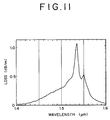
- the doping with Er throughout the whole body of the core 22a leads to the result that the Er distribution within the core 22a below the threshold value of the pumping light does not contribute to the amplification. Accordingly, as shown in the absorption loss characteristic of erbium in FIG. 11, the absorption loss around the wavelength 1.536 ⁇ m is increased. Thereby, the light generated by spontaneous emission within the core 22a around the wavelength 1.536 ⁇ m can be reduced.
- a signal light with the wavelength 1.55 ⁇ m may be used in connection with the inventive optical fiber because the light due to spontaneous emission around the wavelength 1.53 ⁇ m is eliminated.
- the generation of the light by spontaneous emission around the wavelength 1.53 ⁇ m can be reduced and, in addition, the energy of the pumping light that has been used for amplification of the light due to spontaneous emission can be utilized for the amplification of the signal light of the wavelength 1.55 ⁇ m, an improvement in the amplification efficiency of the signal light can be achieved.
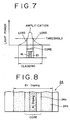
- FIG. 8 there is shown a sectional view of an optical fiber 24 of a second embodiment of the present invention suitable for use in an optical fiber amplifier.
- the Er doped optical fiber 24 in the second embodiment is arranged such that the center portion of its core 24a is doped with aluminum, while the whole body of the core 24a and a portion of the cladding 24b are doped with erbium.
- the doping of the cladding 24b with erbium it is preferred that the Er doping becomes less concentrated toward the circumference of the cladding 24b. That is, since the light power becomes lower toward the circumference of the optical fiber 24, a smaller quantity of Er doping is sufficient to suppress the generation of the light by spontaneous emission there.
- the erbium distribution below the threshold value of the pumping light contributing to amplification is increased as shown in FIG. 9, and hence the absorption loss caused on the wavelength around 1.53 ⁇ m can be increased.
- the light around the wavelength 1.536 ⁇ m band generated by spontaneous emission within the core 24a and cladding 24b can be reduced.
- the light around the wavelength 1.53 ⁇ m band generated by spontaneous emission within the cladding can be reduced, and therefore, the S/N ratio of the amplified signal light can be improved over that in the example shown in FIG. 7.
- the signal light of the wavelength 1.55 ⁇ m is used in this embodiment the same as in the example described as related with FIG. 7.
Landscapes
- Physics & Mathematics (AREA)
- Electromagnetism (AREA)
- Engineering & Computer Science (AREA)
- Plasma & Fusion (AREA)
- Optics & Photonics (AREA)
- Lasers (AREA)
Description
- The present invention relates to an optical fiber suitable for use in an optical fiber amplifier for directly amplifying signal light. In the journal Electronic Letters, vol. 26, no. 10, May 1, 1990, pages 661-662 an optical fiber amplifier with a high gain 2-stage amplification stage is disclosed. This optical fiber amplifier employs for the 2-stage construction optical fibers, which are doped with erbium for amplifying signal light inputted into the optical fiber amplifier.
- In an optical communication system practically used at present, a repeater is inserted at fixed distance intervals, so as to compensate the attenuation of an optical signal due to a loss in an optical fiber. The repeater is constructed in such a manner, that the optical signal is converted into an electrical signal by a photodiode, followed by amplification of the electrical signal by means of an electronic amplifier. Thereafter the electrical signal thus amplified is converted into an optical signal by means of a semiconductor laser or the like, followed by returning of the optical signal to an optical transmission line. If the optical signal can be directly amplified with a low noise as it stands, the optical repeater can be made compact and economized.
- In this circumstance, many researches in an optical amplifier capable of directly amplifying an optical signal have been greatly developed. The optical amplifier subjected to the researches is generally classified into (a) an optical fiber amplifier employing, in combination, an optical fiber doped with a rare earth element (Er, Nb, Yb, etc.) and a pumping light; (b) an optical amplifier employing a semiconductor laser doped with the rare earth element; and (c) an optical amplifier utilizing a nonlinear effect in the optical fiber.
- Above all, the optical fiber amplifier employing the combination of the rare earth element doped fiber and the pumping light as mentioned in the above type (a) has excellent features such as no polarization dependency, low noise, and small coupling loss to a transmission line. Accordingly, the optical amplifier of this type is expected to remarkably increase a repeating distance in an optical fiber transmission system, and it is also expected to enable multiple distributions of the optical signal.
- The principle of the optical amplification achieved by means of a rare earth doped fiber will be described below. If a pumping light beam is introduced into an optical fiber having its core doped with erbium, Er atoms are excited to a higher energy level. Then, if a signal light beam is allowed to impinge on the Er atoms in the optical fiber excited to the high level, the Er atoms undergo a transition to a lower energy level and stimulated emission of radiation occurs. Then, power of the signal light progressively increases as it propagates through the optical fiber and thus amplification of the signal light is achieved.
- Optical fiber amplifiers operating on the above described principle are extensively developed. A conventional optical fiber amplifier is structured as described below. That is, a signal light beam is introduced into an Er doped optical fiber through an optical isolator, and at the same time, a pumping light beam emitted from a pumping light source is introduced therein through an optical isolator and a wavelength multiplexer/demultiplexer. By making light power of the pumping light sufficiently great, Er atoms within the Er doped optical fiber can be excited to a higher energy level, so that, by the introduced signal light, stimulated emission of light with the same wavelength takes place and an amplified signal light beam is emitted through the wavelength multiplexer/demultiplexer and an optical isolator to the transmission line.
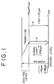
- The optical amplifying action performed by the Er doped optical fiber will be described with reference to the energy level diagram of FIG. 1. Er atoms are raised from the ground level (⁴I15/2) to the excited level by optical energy of the pumping light with the wavelength 0.98 µm or 1.48 µm and undergo transition within the excited level and fall to the level of 1.55 µm band (⁴I13/2). At this time, if a light beam of the wavelength 1.536 µm is introduced as the signal light, stimulated emission of the Er atoms staying at the 1.55 µm band level takes place as indicated by the arrow "A" and the signal light is thereby amplified.
- At the same time, light due to spontaneous emission with wavelengths 1.53 to 1.57 µm is generated as indicated by the arrow "B" on account of expansion of the 1.55 µm band level. However, the light generated by spontaneous emission in the Er doped optical fiber is amplified within the Er doped optical fiber by the energy of the pumping light as with the signal light, and thereby, the amplification of the signal light is adversely affected and the S/N ratio of the signal light is deteriorated.
- Accordingly, the object of the present invention is to provide an optical fiber which, when used in an optical fiber amplifier, can perform proper amplification of the signal light and which prevents spontaneous emissions to have an adverse effect on the signal light, thus improving the S/N ration for the signal wavelength.
- This object is solved by an optical fiber according to claim 1.
- Such an optical fiber can advantageously be used in an optical amplifier. For example there is provided an optical fiber amplifier adapted such that signal light and pumping light are propagated through an optical fiber doped with erbium and the signal light is thereby amplified, wherein a wavelength demultiplexer for eliminating light generated within the optical fiber by spontaneous emission from the optical fiber is inserted in the optical fiber.
- According to the above described arrangement, since the light due to spontaneous emission is eliminated from the erbium doped optical fiber by the wavelength demultiplexer, the signal light is properly amplified in the doped optical fiber.
- Another example is an optical fiber amplifier adapted such that signal light and pumping light are propagated through an optical fiber doped with erbium and the signal light is thereby amplified, wherein the optical fiber is arranged in a coil form with a radius of curvature causing a little bend loss on the signal light and a great bend loss on light due to spontaneous emission on the longer wavelength side than the signal light.
- According to the above described arrangement, since the light due to spontaneous emission on the longer wavelength side is eliminated by the bend loss in the doped optical fiber, the signal light is properly amplified in the doped optical fiber.
- According to claim 1, there is provided an optical fiber suitable for use in an optical fiber amplifier for directly amplifying signal light comprising: a core of which the whole body is doped with erbium and only the center portion is additionally doped with aluminum; and a cladding surrounding the core, with a lower index of refraction than the core.
- By the use of the optical fiber of claim 1 in the optical fiber amplifier, the fluorescence of the wavelength affecting the signal light is reduced by the doping with aluminum of the center portion of the core. Further, by the uniform doping with erbium of the whole body of the core, the erbium distribution below the threshold value of the pumping light is kept from contributing to the amplification, which leads to an increase in the absorption loss caused on the wavelength close to that of the signal light. Thus, it is made possible to reduce the light due to spontaneous emission with the wavelength adversely affecting the amplification of the signal light.
- By doping not only the core but also a portion or the whole body of the cladding with erbium, not only the light due to spontaneous emission generated in the core can be reduced but also that generated in the cladding can be reduced.
- The above and other objects, features, and advantages of the present invention and the manner of realizing them will become more apparent, and the invention itself will best be understood from a study of the following description and appended claims with reference to the attached drawings showing some preferred embodiments of the invention.
- FIG. 1 is an energy level diagram for explaining the action in a prior art optical fiber amplifier;
- FIG. 2 is a schematic structural diagram of an example of an optical fiber amplifier;
- FIG. 3 is a schematic structural diagram of another example of an optical fiber amplifier;
- FIG. 4 is a schematic structural diagram of a further example of an optical fiber amplifier;
- FIG. 5 is a schematic diagram showing a relationship between the gain in an Er doped optical fiber and the radius of curvature;
- FIG. 6 is a fragmentary sectional view of a first embodiment of an inventive Er doped optical fiber suitable for use in an optical fiber amplifier;
- FIG. 7 is a schematic diagram for explaining the amplifying action performed in the doped optical fiber shown in FIG. 6;
- FIG. 8 is a fragmentary sectional view of a second embodiment of an inventive Er doped optical fiber suitable for use in an optical fiber amplifier;
- FIG. 9 is a schematic diagram for explaining the amplifying action performed in the doped optical fiber shown in FIG. 8;
- FIG. 10 is a graph showing fluorescent characteristics of an optical fiber whose core is doped only with erbium and an optical fiber whose core is doped with erbium/aluminum; and
- FIG. 11 is a graph showing an absorption loss characteristic of erbium.
- First, an example of an optical fiber amplifier will now be described with reference to FIG. 2. This optical amplifier is of a backward pumping arrangement in which the pumping light is introduced in the opposite direction to the propagating direction of the signal light.
Reference numerals wavelength demultiplexer 20. Thewavelength demultiplexer 20 is provided for separating, from the dopedoptical fibers light input end 11. - Pumping light with the wavelength 1.48 µm emitted from a
pumping light source 13 propagates through anoptical isolator 14 and a wavelength multiplexer/demultiplexer 15 and, further, through an Er dopedoptical fiber 10a and awavelength demultiplexer 20, down to an Er dopedoptical fiber 10b. When the pumping light having sufficiently great light power is introduced into the Er dopedoptical fibers optical fibers - Meanwhile, the signal light having the wavelength 1.536 µm introduced from the signal
light input end 11 is led into the Er dopedoptical fiber 10b through anoptical isolator 12, and therein, the signal light is amplified by stimulated emission. At this time, light due to spontaneous emission is also generated, but the light on the higher wavelength side than the signal light having the wavelength 1.55 µm and above is separated from the signal light and discharged by thewavelength demultiplexer 20. The signal light output from thewavelength demultiplexer 20 is led into the Er dopedoptical fiber 10a, where the signal light is amplified still more by stimulated emission to be output from the signallight output end 17 through the wavelength multiplexer/demultiplexer 15 and anoptical isolator 16. The light generated by spontaneous emission within the Er dopedoptical fiber 10a is not allowed to enter the Er dopedoptical fiber 10b because the light on the higher wavelength side than the signal light, having the wavelength 1.55 µm and above, is separated from the signal light and discharged by thewavelength demultiplexer 20. - As described above, of the light generated by spontaneous emission in the Er doped
optical fibers wavelength demultiplexer 20. Therefore, the amplifying performance of the signal light is kept from being adversely affected by the light due to spontaneous emission, and the S/N ratio of the amplified signal light can be improved. Further, since it becomes possible to allow the portion of the energy of the pumping light that has been used for amplification of the light due to spontaneous emission to contribute to the amplification of the signal light, an improvement in the amplification efficiency of the signal light can be achieved. - Although, in the present example only one
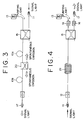
wavelength demultiplexer 20 is inserted between the Er dopedoptical fibers - Now, an example of an optical amplifier of a forward pumping arrangement in which the signal light and the pumping light are propagated in the same direction will be described with reference to FIG. 3.
- According to this arrangement, the pumping light with the wavelength 1.48 µm emitted from the pumping
light source 13 is propagated through the wavelength multiplexer/demultiplexer 15 and, then, through the Er dopedoptical fiber 10a and thewavelength demultiplexer 20 down to the Er dopedoptical fiber 10b. Meanwhile, the signal light with the wavelength 1.536 µm entering the signallight input end 11 is passed through the wavelength multiplexer/demultiplexer 15 to be introduced into the Er dopedoptical fiber 10a, where it is amplified by stimulated emission. At this time, light is also generated by spontaneous emission as described in the first embodiment. From the light thus generated by spontaneous emission, that having the wavelength 1.55 µm or above, i.e., on the longer wavelength side than the signal light, is eliminated by thewavelength demultiplexer 20 in the subsequent stage. - Accordingly, only the signal light is output from the
wavelength demultiplexer 20 to be input to the Er dopedoptical fiber 10b. This signal light is further amplified by stimulated emission in the Er dopedoptical fiber 10b and emitted from the signallight output end 17 through the optical isolator 19. Of the light generated in the Er dopedoptical fiber 10b by spontaneous emission, that with the wavelength 1.55 µm or above is separated from the signal light by thewavelength demultiplexer 20 and, hence, it is not introduced into the Er dopedoptical fiber 10a. Therefore, also in this example, it is made possible to properly amplify the signal light. - Now, a further example of an optical fiber amplifier of a backward pumping arrangement will be described with reference to FIG. 4. In this example, a coil-formed Er doped
optical fiber 21 is used. The coil-formed Er dopedoptical fiber 21 is arranged in a coil form with its radius of curvature set such that the bend loss caused on the signal light with the wavelength 1.536 µm is small but the bend loss caused on the light generated by spontaneous emission in the Er dopedoptical fiber 21, with the wavelength on the higher wavelength side than the signal light generated in the Er doped optical fiber 21 (with the wavelength 1.55 µm or above), is great. - The preferable radius of curvature is approximately 20 mm. As understood from the relationship between the radius of curvature R and the gain in the Er doped
optical fiber 21 shown in FIG. 5, the most reasonable gain of the Er dopedoptical fiber 21 eliminating the light due to spontaneous emission with the wavelength 1.55 µm or above and amplifying the signal light with the wavelength 1.536 µm is obtained when the radius of curvature R = 20 mm ± 3 mm. As apparent from FIG. 5, the gain markedly decreases when the radius of curvature R = 13 mm or below. - According to the arrangement of FIG. 4, the pumping light with the wavelength 1.48 µm emitted from the pumping
light source 13 is propagated through theoptical isolator 14 and the wavelength multiplexer/demultiplexer 15 down to the coil-formed Er dopedoptical fiber 21, and excites Er atoms within theoptical fiber 21 to a higher energy level. Meanwhile, the signal light with the wavelength 1.536 µm input to the signallight input end 11 is introduced, through theoptical isolator 12, into the coil-formed Er dopedoptical fiber 21, wherein the signal light is amplified by stimulated emission. The light generated by spontaneous emission at this time with the wavelength 1.55 µm or above is not allowed to propagate through the coil-formedoptical fiber 21 but eliminated because of the great bend loss of the coil-formedoptical fiber 21. The signal light being amplified while propagating through the coil-formed Er dopedoptical fiber 21 is passed through the wavelength multiplexer/demultiplexer 15 and theoptical isolator 16 to be emitted from the signallight output end 17. - According to this example, since the light due to spontaneous emission with the wavelength larger than 1.55 µm is eliminated and the signal light with the wavelength 1.536 µm is amplified by the coil-formed Er doped
optical fiber 21, the signal light can be amplified without deteriorating its S/N ratio. The present example is one which is applied to the backward pumping arrangement but it can be equally applied to the forward pumping arrangement shown in FIG. 3 in which the signal light and the pumping light propagate in the same direction. - Now, an optical fiber according to a first embodiment of the invention will be described with reference to FIG. 6, FIG. 7, FIG. 10, and FIG. 11. This optical fiber comprises an Er doped
optical fiber 22 having a structure as shown in the sectional view of FIG. 6. - The Er doped
optical fiber 22 shown in FIG. 6 is arranged such that the center portion of its core 22a is doped with aluminum, while the whole body of the core 22a is doped with erbium. - The light power in the Er doped
optical fiber 22 of the described structure is distributed as shown in FIG. 7. By the doping of the center portion of the core 22a with aluminum, the fluorescent characteristic of the doped optical fiber is shifted to a band around 1.55 µm as shown in FIG. 10 and, hence, the fluorescence in the vicinity of 1.536 µm is reduced. Accordingly, generation of the light by spontaneous emission around the 1.536 µm band can be reduced. Further, the doping with Er throughout the whole body of the core 22a leads to the result that the Er distribution within the core 22a below the threshold value of the pumping light does not contribute to the amplification. Accordingly, as shown in the absorption loss characteristic of erbium in FIG. 11, the absorption loss around the wavelength 1.536 µm is increased. Thereby, the light generated by spontaneous emission within the core 22a around the wavelength 1.536 µm can be reduced. - While the signal light with the wavelength 1.536 µm was used in the above described examples of optical fiber amplifiers, a signal light with the wavelength 1.55 µm may be used in connection with the inventive optical fiber because the light due to spontaneous emission around the wavelength 1.53 µm is eliminated.
- By the use of the Er doped
optical fiber 22 shown in FIG. 6, the generation of the light by spontaneous emission around the wavelength 1.53 µm can be reduced and, in addition, the energy of the pumping light that has been used for amplification of the light due to spontaneous emission can be utilized for the amplification of the signal light of the wavelength 1.55 µm, an improvement in the amplification efficiency of the signal light can be achieved. - Referring now to FIG. 8, there is shown a sectional view of an
optical fiber 24 of a second embodiment of the present invention suitable for use in an optical fiber amplifier. - The Er doped
optical fiber 24 in the second embodiment is arranged such that the center portion of its core 24a is doped with aluminum, while the whole body of the core 24a and a portion of thecladding 24b are doped with erbium. As to the doping of thecladding 24b with erbium, it is preferred that the Er doping becomes less concentrated toward the circumference of thecladding 24b. That is, since the light power becomes lower toward the circumference of theoptical fiber 24, a smaller quantity of Er doping is sufficient to suppress the generation of the light by spontaneous emission there. By doping not only the core but also a part of the cladding with erbium as described above, the erbium distribution below the threshold value of the pumping light contributing to amplification is increased as shown in FIG. 9, and hence the absorption loss caused on the wavelength around 1.53 µm can be increased. Thus, the light around the wavelength 1.536 µm band generated by spontaneous emission within the core 24a andcladding 24b can be reduced. - In the present embodiment, the light around the wavelength 1.53 µm band generated by spontaneous emission within the cladding can be reduced, and therefore, the S/N ratio of the amplified signal light can be improved over that in the example shown in FIG. 7. Of course, the signal light of the wavelength 1.55 µm is used in this embodiment the same as in the example described as related with FIG. 7.
Claims (3)
- An optical fiber (10a, 10b, 21, 22, 24) suitable for use in an optical fiber amplifier for directly amplifying signal light, comprising:a) a core (22a, 24a) of the optical fiber (24), the whole of which is doped with erbium; andb) a cladding (24b) surrounding said core (24a), which has a lower refractive index than said core (24a); andc) only a center portion of said core (24a) being additionally doped with aluminum.
- An optical fiber according to claim 1, characterized in that a portion of said cladding (24b) towards the center of the optical fiber is also doped with erbium.
- An optical fiber according to claim 1, characterized in that the whole body of said cladding (24b) is also doped with erbium.
Applications Claiming Priority (4)
| Application Number | Priority Date | Filing Date | Title |
|---|---|---|---|
| JP2201440A JP2834867B2 (en) | 1990-07-31 | 1990-07-31 | Erbium-doped fiber amplifier |
| JP201440/90 | 1990-07-31 | ||
| JP57417/91 | 1991-03-20 | ||
| JP3057417A JP2998247B2 (en) | 1991-03-20 | 1991-03-20 | Erbium fiber for optical amplifier |
Publications (3)
| Publication Number | Publication Date |
|---|---|
| EP0470497A2 EP0470497A2 (en) | 1992-02-12 |
| EP0470497A3 EP0470497A3 (en) | 1992-05-06 |
| EP0470497B1 true EP0470497B1 (en) | 1995-10-11 |
Family
ID=26398459
Family Applications (1)
| Application Number | Title | Priority Date | Filing Date |
|---|---|---|---|
| EP91112890A Expired - Lifetime EP0470497B1 (en) | 1990-07-31 | 1991-07-31 | Optical fiber amplifier |
Country Status (4)
| Country | Link |
|---|---|
| US (1) | US5155621A (en) |
| EP (1) | EP0470497B1 (en) |
| CA (1) | CA2048145C (en) |
| DE (1) | DE69113714T2 (en) |
Families Citing this family (29)
| Publication number | Priority date | Publication date | Assignee | Title |
|---|---|---|---|---|
| GB2264807B (en) * | 1992-02-20 | 1995-10-04 | Univ Southampton | Optical amplifier |
| GB2266620B (en) * | 1992-04-27 | 1996-08-28 | Univ Southampton | Optical power limited amplifier |
| JP3214910B2 (en) * | 1992-08-18 | 2001-10-02 | 富士通株式会社 | Manufacturing method of planar waveguide optical amplifier |
| GB9318688D0 (en) * | 1993-09-09 | 1993-10-27 | Northern Telecom Ltd | Optical amplifiers |
| US5363234A (en) * | 1993-10-14 | 1994-11-08 | Corning Incorporated | Amplifier having pump fiber filter |
| JP3244579B2 (en) * | 1993-12-17 | 2002-01-07 | 富士通株式会社 | Optical fiber amplifier |
| US5604628A (en) * | 1994-12-30 | 1997-02-18 | Cornell Research Foundation, Inc. | Optical laser amplifier combined with a spontaneous emission filter |
| JP3556026B2 (en) * | 1995-10-30 | 2004-08-18 | 富士通株式会社 | Multi-wavelength optical amplifier that amplifies multiple wavelength signals at once |
| KR970064034A (en) * | 1996-02-10 | 1997-09-12 | 김광호 | Optical transmission systems and lasers for multi-wavelength automatic power and gain control |
| DE19622012A1 (en) * | 1996-05-31 | 1997-12-04 | Siemens Ag | Remotely pumped optical power amplifier |
| JPH1011022A (en) | 1996-06-18 | 1998-01-16 | Sharp Corp | Driving circuit of display device |
| CA2205705A1 (en) * | 1996-06-26 | 1997-12-26 | Franklin W. Kerfoot, Iii | Arrangement for reducing insertion loss impairment of optical amplifiers |
| US6289698B1 (en) * | 1996-08-02 | 2001-09-18 | Corning Incorporated | Method of making a fiber preform with increases in alumina concentration at radial distances |
| US5877890A (en) * | 1996-10-30 | 1999-03-02 | Rutgers, The State University Of New Jersey | Optical-fiber amplifier having high-saturation output |
| GB2366447B (en) * | 1996-12-04 | 2002-04-17 | Southampton Photonics Ltd | Apparatus for Amplifying a Signal Beam having a Normalised Intensity Distribution |
| US6275512B1 (en) | 1998-11-25 | 2001-08-14 | Imra America, Inc. | Mode-locked multimode fiber laser pulse source |
| US6192179B1 (en) | 1999-01-25 | 2001-02-20 | Corning Incorporated | Distributed resonant ring fiber filter |
| US6459526B1 (en) * | 1999-08-09 | 2002-10-01 | Corning Incorporated | L band amplifier with distributed filtering |
| US6477297B1 (en) * | 2000-03-08 | 2002-11-05 | Corning Incorporated | Reduction of bend loss through constraint of optical fiber parameters |
| US6724528B2 (en) | 2001-02-27 | 2004-04-20 | The United States Of America As Represented By The Secretary Of The Navy | Polarization-maintaining optical fiber amplifier employing externally applied stress-induced birefringence |
| US6516124B2 (en) * | 2001-03-02 | 2003-02-04 | Optical Power Systems Incorporated | Fiber for enhanced energy absorption |
| KR100349007B1 (en) | 2001-09-07 | 2002-08-17 | Lg Cable Ltd | Low noise optical amplifying device and optical communication system using the same |
| US6775348B2 (en) * | 2002-02-27 | 2004-08-10 | General Electric Company | Fiber optic scintillator with optical gain for a computed tomography system and method of manufacturing same |
| US7400812B2 (en) * | 2003-09-25 | 2008-07-15 | Nufern | Apparatus and methods for accommodating loops of optical fiber |
| US7046902B2 (en) * | 2003-09-30 | 2006-05-16 | Coractive High-Tech Inc. | Large mode field diameter optical fiber |
| US7526167B1 (en) * | 2005-06-24 | 2009-04-28 | Lockheed Martin Corporation | Apparatus and method for a high-gain double-clad amplifier |
| US7768700B1 (en) | 2006-11-30 | 2010-08-03 | Lockheed Martin Corporation | Method and apparatus for optical gain fiber having segments of differing core sizes |
| US20090059352A1 (en) * | 2007-08-30 | 2009-03-05 | Furukawa Electric North America, Inc. | Method and arrangement for mitigating bend distortion impact in a fiber amplifier or laser |
| JP4834718B2 (en) * | 2008-01-29 | 2011-12-14 | キヤノン株式会社 | Pulse laser device, terahertz generator, terahertz measuring device, and terahertz tomography device |
Family Cites Families (13)
| Publication number | Priority date | Publication date | Assignee | Title |
|---|---|---|---|---|
| US3615312A (en) * | 1969-04-21 | 1971-10-26 | American Optical Corp | End fusion of glass laser rods of dissimilar chemistry |
| US3963347A (en) * | 1974-05-09 | 1976-06-15 | American Optical Corporation | Erbium laser ceilometer |
| FR2331900A1 (en) * | 1975-11-13 | 1977-06-10 | Commissariat Energie Atomique | WAVELENGTH SELECTIVE SWITCH DEVICE |
| DE2926977A1 (en) * | 1979-07-04 | 1981-01-22 | Licentia Gmbh | Curved optical fibre wavelength filter - selectively couples light from core to cladding to form high or low pass |
| US4556279A (en) * | 1981-11-09 | 1985-12-03 | Board Of Trustees Of The Leland Stanford Junior University | Passive fiber optic multiplexer |
| US4938556A (en) * | 1983-11-25 | 1990-07-03 | The Board Of Trustees Of The Leland Stanford Junior University | Superfluorescent broadband fiber laser source |
| WO1986002171A1 (en) * | 1984-10-01 | 1986-04-10 | Polaroid Corporation | Optical waveguide amplifier and laser |
| US4708421A (en) * | 1985-02-08 | 1987-11-24 | The Board Of Trustees Of The Leland Stanford Junior University | In-line fiber optic memory |
| JPH0681119B2 (en) * | 1986-04-17 | 1994-10-12 | 日本電気株式会社 | WDM optical transmission system |
| GB8724736D0 (en) * | 1987-10-22 | 1987-11-25 | British Telecomm | Optical fibre |
| JPH01302205A (en) * | 1988-05-30 | 1989-12-06 | Fujikura Ltd | Optical fiber filter |
| US5087108A (en) * | 1989-08-11 | 1992-02-11 | Societa' Cavi Pirelli S.P.A. | Double-core active-fiber optical amplifier having a wide-band signal wavelength |
| US5005175A (en) * | 1989-11-27 | 1991-04-02 | At&T Bell Laboratories | Erbium-doped fiber amplifier |
-
1991
- 1991-07-29 US US07/736,932 patent/US5155621A/en not_active Expired - Lifetime
- 1991-07-30 CA CA002048145A patent/CA2048145C/en not_active Expired - Fee Related
- 1991-07-31 DE DE69113714T patent/DE69113714T2/en not_active Expired - Fee Related
- 1991-07-31 EP EP91112890A patent/EP0470497B1/en not_active Expired - Lifetime
Also Published As
| Publication number | Publication date |
|---|---|
| US5155621A (en) | 1992-10-13 |
| CA2048145A1 (en) | 1992-02-01 |
| CA2048145C (en) | 1994-11-01 |
| DE69113714T2 (en) | 1996-04-18 |
| EP0470497A3 (en) | 1992-05-06 |
| EP0470497A2 (en) | 1992-02-12 |
| DE69113714D1 (en) | 1995-11-16 |
Similar Documents
| Publication | Publication Date | Title |
|---|---|---|
| EP0470497B1 (en) | Optical fiber amplifier | |
| JP2734209B2 (en) | Optical fiber amplifier | |
| EP0968579B1 (en) | Multiple stage optical fiber amplifier | |
| JP2971561B2 (en) | Erbium-doped fiber amplifier | |
| US6233092B1 (en) | Management and utilization of ASE in optical amplifier | |
| US5287216A (en) | Fiber amplifier with multiple pumps | |
| US5140598A (en) | Fiber optic amplifier | |
| US6252700B1 (en) | Erbium doped fiber amplifier suitable for long wavelength light signal | |
| US7095552B2 (en) | Raman optical fiber amplifier using erbium doped fiber | |
| US20010022884A1 (en) | C-band multimode cladding optical fiber amplifier | |
| JP3045550B2 (en) | Broadband active fiber optic amplifier with multiple multi-core fiber sections | |
| JPH1174597A (en) | Optical amplifier with absorber | |
| US7012741B2 (en) | Wideband amplifier with erbium-doped fiber | |
| US6583922B2 (en) | Optical amplifier site with reduced noise and transmission system utilizing such | |
| JP2834867B2 (en) | Erbium-doped fiber amplifier | |
| JP2947983B2 (en) | Optical fiber amplifier | |
| US6606190B2 (en) | Inhomogeneity tunable erbium-doped fiber amplifier with long wavelength gain band and method of blocking propagation of backward amplified spontaneous light emission in the same | |
| US6504647B1 (en) | Optical fiber amplifier, a method of amplifying optical signals, optical communications system | |
| JPH09138432A (en) | Optical amplifier | |
| JP3361409B2 (en) | Optical fiber amplifier | |
| KR0138960B1 (en) | High efficiency fiber optic amplifier | |
| JP3086033B2 (en) | 1.3μm band optical amplifier | |
| KR100341215B1 (en) | Two-stage optical amplifier using long-band of erbium doped fiber | |
| JP2737596B2 (en) | Optical fiber amplifier | |
| JPH1041570A (en) | Optical amplifier |
Legal Events
| Date | Code | Title | Description |
|---|---|---|---|
| PUAI | Public reference made under article 153(3) epc to a published international application that has entered the european phase |
Free format text: ORIGINAL CODE: 0009012 |
|
| AK | Designated contracting states |
Kind code of ref document: A2 Designated state(s): DE FR GB |
|
| PUAL | Search report despatched |
Free format text: ORIGINAL CODE: 0009013 |
|
| AK | Designated contracting states |
Kind code of ref document: A3 Designated state(s): DE FR GB |
|
| 17P | Request for examination filed |
Effective date: 19921016 |
|
| 17Q | First examination report despatched |
Effective date: 19930825 |
|
| GRAA | (expected) grant |
Free format text: ORIGINAL CODE: 0009210 |
|
| AK | Designated contracting states |
Kind code of ref document: B1 Designated state(s): DE FR GB |
|
| REF | Corresponds to: |
Ref document number: 69113714 Country of ref document: DE Date of ref document: 19951116 |
|
| ET | Fr: translation filed | ||
| PLBE | No opposition filed within time limit |
Free format text: ORIGINAL CODE: 0009261 |
|
| STAA | Information on the status of an ep patent application or granted ep patent |
Free format text: STATUS: NO OPPOSITION FILED WITHIN TIME LIMIT |
|
| 26N | No opposition filed | ||
| REG | Reference to a national code |
Ref country code: GB Ref legal event code: IF02 |
|
| PGFP | Annual fee paid to national office [announced via postgrant information from national office to epo] |
Ref country code: FR Payment date: 20060719 Year of fee payment: 16 |
|
| PGFP | Annual fee paid to national office [announced via postgrant information from national office to epo] |
Ref country code: GB Payment date: 20060726 Year of fee payment: 16 |
|
| PGFP | Annual fee paid to national office [announced via postgrant information from national office to epo] |
Ref country code: DE Payment date: 20060727 Year of fee payment: 16 |
|
| GBPC | Gb: european patent ceased through non-payment of renewal fee |
Effective date: 20070731 |
|
| PG25 | Lapsed in a contracting state [announced via postgrant information from national office to epo] |
Ref country code: DE Free format text: LAPSE BECAUSE OF NON-PAYMENT OF DUE FEES Effective date: 20080201 |
|
| PG25 | Lapsed in a contracting state [announced via postgrant information from national office to epo] |
Ref country code: GB Free format text: LAPSE BECAUSE OF NON-PAYMENT OF DUE FEES Effective date: 20070731 |
|
| REG | Reference to a national code |
Ref country code: FR Ref legal event code: ST Effective date: 20080331 |
|
| PG25 | Lapsed in a contracting state [announced via postgrant information from national office to epo] |
Ref country code: FR Free format text: LAPSE BECAUSE OF NON-PAYMENT OF DUE FEES Effective date: 20070731 |