EP0470366A2 - Leak detecting method for vessels - Google Patents
Leak detecting method for vessels Download PDFInfo
- Publication number
- EP0470366A2 EP0470366A2 EP91110993A EP91110993A EP0470366A2 EP 0470366 A2 EP0470366 A2 EP 0470366A2 EP 91110993 A EP91110993 A EP 91110993A EP 91110993 A EP91110993 A EP 91110993A EP 0470366 A2 EP0470366 A2 EP 0470366A2
- Authority
- EP
- European Patent Office
- Prior art keywords
- light
- laser light
- absorption cell
- line laser
- gas
- Prior art date
- Legal status (The legal status is an assumption and is not a legal conclusion. Google has not performed a legal analysis and makes no representation as to the accuracy of the status listed.)
- Granted
Links
Images


Classifications
-
- G—PHYSICS
- G01—MEASURING; TESTING
- G01M—TESTING STATIC OR DYNAMIC BALANCE OF MACHINES OR STRUCTURES; TESTING OF STRUCTURES OR APPARATUS, NOT OTHERWISE PROVIDED FOR
- G01M3/00—Investigating fluid-tightness of structures
- G01M3/02—Investigating fluid-tightness of structures by using fluid or vacuum
- G01M3/04—Investigating fluid-tightness of structures by using fluid or vacuum by detecting the presence of fluid at the leakage point
- G01M3/20—Investigating fluid-tightness of structures by using fluid or vacuum by detecting the presence of fluid at the leakage point using special tracer materials, e.g. dye, fluorescent material, radioactive material
- G01M3/22—Investigating fluid-tightness of structures by using fluid or vacuum by detecting the presence of fluid at the leakage point using special tracer materials, e.g. dye, fluorescent material, radioactive material for pipes, cables or tubes; for pipe joints or seals; for valves; for welds; for containers, e.g. radiators
- G01M3/226—Investigating fluid-tightness of structures by using fluid or vacuum by detecting the presence of fluid at the leakage point using special tracer materials, e.g. dye, fluorescent material, radioactive material for pipes, cables or tubes; for pipe joints or seals; for valves; for welds; for containers, e.g. radiators for containers, e.g. radiators
Definitions
- the present invention relates to a leak detecting method for vessels such as pressure vessels and hermetically sealed vessels and more particularly to a leak detecting method for vessels which employs sulfur hexafluoride as a tracer gas to utilize the absorption of a carbon dioxide gas P-(16)-line laser light by the tracer gas.
- the method of using a helium gas is disadvantageous in that since the vessel is placed within the high vacuum vessel, a test equipment is considerably increased in size and moreover it is difficult to deduce the locations of any leaks.
- the present invention has been made to overcome the foregoing deficiencies in the prior art and it is an object of the invention to provide a leak detecting method for vessels which is so designed that the location of any leakage can be presumed without using any Freon gas and also no high vacuum vessel is required.
- a leak detecting method for vessels which comprises mixing a gas of a given pressure with sulfur hexafluoride of a given partial pressure and introducing the mixture into a vessel, sucking the gas in the vicinity of the outer peripheral surface of the vessel by a gas sucking mechanism to introduce the sucked gas into an absorption cell, introducing the P(16)-line laser light of a carbon dioxide gas laser into the absorption cell, detecting the presence of absorption of the P(16)-line laser light within the absorption cell in accordance with a change in the amount of light transmitted through the absorption cell, and discriminating the presence of any leakage from the vessel in accordance with the result of the detection.
- a leak detecting method for vessels which comprises mixing a gas of a given pressure with sulfur hexafluoride of a given partial pressure and introducing the same into a vessel, sucking the gas in the vicinity of the outer peripheral surface of the vessel by a gas sucking machanism to introduce the sucked gas into a multiple reflection absorption cell, introducing the P(16)-line laser light of a carbon dioxide gas laser and a reference light which is slightly different in wavelength from the P(16)-line laser light into the multiple reflection absorption cell, detecting the presence of absorption of the P(16)-line laser light within the multiple reflection absorption cell in accordance with a change in the ratio between the light intensities of the both reflected lights of the introduced lights, and discriminating the presence of leakage of the vessel in accordance with the result of the detection.
- Fig. 1 is a schematic block diagram showing the construction of a leak detecting apparatus for pressure vessels according to an embodiment of the present invention.
- numeral 1 designates a pressure vessel and the interior of which is pressurized by an externally supplied air mixed with sulfur hexafluoride (hereinafter referred to as SF 6 ).
- Numeral 2 designates the welds of the pressure vessel 1 where the tendency to cause leakage is highest.
- Numeral 3 designates an air suction port which is formed for example into a funnel shape and including a lower part having a flexible skirt so as to be convenient for the sucking of air while being moved and an upper part connected to one end of a flexible pipe 4 for air exhausting purposes.
- the position of the air suction port 3 is subjected to profiling control by a profile robot 17 which is preliminarily taught about the positions of the welds 2.
- the other end of the flexible pipe 4 is connected to the air inlet of an absorption cell 5.
- the absorption cell 5 is a closed container having ends made of a substance transparent to light of wavelengths in the infrared region and a given cell length (e.g., 30 cm) and including an air inlet and an air outlet.
- the air inlet of the absorption cell 5 is connected to the suction port 3 through the flexible pipe 4 and its air outlet is connected to a suction and exhaust unit 6 through a pipe 15.
- air is continuously flowing at a constant flow rate within the absorption cell 5 so that if the air suction port 3 is positioned at the location of a leak, the SF 6 -containing air is introduced into the absorption cell 5.
- a P(16)-line laser light is introduced from a carbon dioxide gas laser into the absorption cell 5.
- Numeral 7 designates the carbon dioxide gas (hereinafter referred to as C0 2 ) laser for emitting a laser light having a wavelength of 10.6 /1.m (hereinafter referred to as a P(16)-line laser light).
- Numeral 8 designates a helium neon (hereinafter referred to as He-Ne) laser which em- ites a red light and is used as an identification laser for checking the optical path of the C0 2 laser.
- Numeral 9 designates a spectral analyzer which is a measuring device for measuring the wavelength of the light emitted by the C0 2 laser 7.
- Numeral 10 designates a light sensor for detecting light near a wavelength of 10.6 /1.m to convert and generate it as an electric signal.
- Numeral 11 designates an amplifier for amplifying the input signal from the light sensor 10 and applying it to an indicator 12 and a leak discriminator 16.
- Numeral 12 designates the indicator for indicating the output of the amplifier 11, 13 a mirror for light reflecting purposes, 14 a half-mirror for reflecting part of the incident light and transmitting part of the incident light, 15 the pipe connecting the air outlet of the absorption cell and the suction and exhaust unit, 16 the leak discriminator for discriminating a leak in accordance with a change in the output signal of the amplifier 11, and 17 the profile robot for profile controlling the position of the suction port 3.
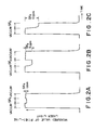
- Figs. 2(a), 2(b) and 2(c) are diagrams showing examples of the measurement of the P(16)-line laser light in the absorption cell of Fig. 1 and each of the examples shows the measured values of the transmitted light intensity of the incident P(16)-line laser light into the absorption cell in cases where a vacuum is produced within the absorption cell and where a mixed gas of SF 6 having a concentration of 1 ppm, 5 ppm or 10 ppm and nitrogen (N 2 ) is sealed, respectively.
- Fig. 1 In order to detect leakage from the pressure vessel 1, the interior of pressure vessel 1 is pressurized by air mixed with SF 6 having a con- centraion of about 5 ppm to 10 ppm. Since the welds 2 and the terminal mounting portion of the vessel generally represent those portions having the highest tendency to cause a leak, the profile robot 17 is preliminarily taught about the shape of the pressure vessel 1 and the positions of the welds 2.
- the profile robot 17 controls the position of the suction port 3 connected to the flexible pipe 4 in such a manner that the suction port 3 is profile controlled along the outer peripheral portion of the pressure vessel 1 so as to scan all of the areas to be inspected such as the welds 2, thereby sucking the air in the vicinity of these areas successively.
- the suction port 3 is not brought into close contact with the outer peripheral surface of the pressure vessel 1 but a small gap is maintained therebetween so that the air near the suction port 3 is also sucked and thus the air of a small flow rate (e.g., several ACC/sec) flows continuously.
- a small flow rate e.g., several ACC/sec
- the suction and exhaust unit 6 continuously effects the suction and exhaustion of the air through the suction port 3, the flexible pipe 4, the absorption cell 5 and the pipe 15.
- the air of the constant flow rate is continuously introduced into the absorption cell 5 from near the suction port 3 so that if the suction port 3 is positioned on the location of a leak such as the weld 2 or the terminal mounting portion, the SF 6 - containing air is introduced into the absorption cell 5 and the air remains temporarily within the cell.
- the C0 2 laser 7 is preliminarily tuned by use of the spectral analyzer 9 and it outputs the P(16)-line laser light (i.e., the laser light having a wavelength of 10.6 /1.m). Also, the output optical path of the C0 2 laser light is preliminarily adjusted by use of the output light (red light) of the identifying He-Ne laser 8 so as to pass along the central axis of the absorption cell 5.
- the ends of the absorption cell 5 are made of a substance which is transparent to light of wavelengths in the infrared region so that the C0 2 laser light having a wavelength of 10.6 ⁇ m is introduced into one end of the absorption cell 5 and its transmitted light is taken out from the other end.
- the SF 6 is present within the absorption cell 5 when the P(16)-line laser light from the C0 2 laser passes through the optical path of absorption cell 5, there is caused a variation in the amount of the transmitted laser light.
- the laser light transmitted through the absorption cell 5 is first converted to an electric signal by the light sensor 10 and it is then amplified by the amplifier 11, thereby generating an output.
- the output of the amplifier 11 is indicated on the indicator 12 and it is also supplied to the leak discriminator 16 which in turn discriminates the presence of leakage from the pressure vessel 1.
- the output of the leak discriminator 16 is fed back to the robot 17 so that while referring to the results of the leak discriminating signals supplied from the leak discriminator 16, the robot 17 controls the position of the suction port 3 in a manner that the positions of leaks and the shape of leakage on the pressure vessel 1 are measured properly.
- FIG. 2(a), 2(b), and 2(c) shows variations in the amount of transmitted light due to the absorption of the incident C0 2 laser light of 10.6 ⁇ m in wavelength in cases where a vacuum is produced within the absorption cell 5 and where N 2 is mixed with a trace amount(1 ppm, 5 ppm or 10 ppm) of SF 6 .
- the leak discriminator 16 can discriminate the presence of leakage of the pressure vessel 1 by discriminating the amount of such variation.
- FIG. 3 there is illustrated a schematic block diagram showing the construction of a leak detecting apparatus for pressure vessels according to another embodiment of the present invention.
- numerals 1, 2, 3, 4, 6, 14, 15 and 17 designate the same component parts as shown in Fig. 1.
- Numeral 21 designates a multiple reflection absorption cell, and the cell 21 is a closed container having an incident light entrance and a reflected light outlet which are made of a substance transparent to light of wavelengths in the infrared region and it also includes an air inlet and an air outlet.
- the incident light introduced through the incident light entrance of the multiple reflection absorption cell 21 is subjected to multiple reflection (that is, the optical path length is extended in an amount corresponding to the multiple reflection) within the cell by oppositely arranged infrared reflection concave mirrors within the cell and the reflected light is delivered to the outside through the reflected light outlet.
- the multiple reflection absorption cell 21 is a sensor so that if SF 6 is mixed with the air sucked into the cell 21, only the incident laser light of 10.6 ⁇ m in wavelength is absorbed in the course of the multiple reflection within the cell and thus its output is delivered as an attenuated light intensity through the reflected light outlet.
- Numeral 22 designates a C0 2 laser which outputs two laser beam of different wavelengths, i.e., a P(16)-line laser light of a wavelength ⁇ 1 , which is 10.6 ⁇ m and a reference light of a wavelength X 2 which is slightly different from the wavelength ⁇ 1 .
- the reference light of the wavelength X 2 may comprise for example a P(18)-line laser light of a wavelength of X 2 which is 10.57 ⁇ m.
- Numeral 23 designates a calibrator and monitor for calibrating and monitoring the C0 2 laser 22 so that two measuring lightwaves slightly different in wavelength (or frequency) from each other are generated from the C0 2 laser 22, and this measuring device is used for effecting the initial calibration of the two light waves of the wavelengths ⁇ 1 and X 2 which are generated from the C0 2 laser 22 and monitored during its operation.
- Numeral 24 designates an optical filter for the lights outputted from the multiple reflection absorption cell 21 and it is composed a filter 1 1 for transmitting only the light of the wavelength ⁇ 1 and a filter 1 2 for transmitting only the light of the wavelength ⁇ 2 .
- Numeral 25 designates a light sensor comprising light detectors mi and m 2 for detecting the lights of the wavelengths ⁇ 1 and X 2 transmitted by the filters 1 1 and 1 2 , respectively.
- Numerals 26-1 and 26-2 designates #1 amplifier and #2 amplifier for respectively amplifying and outputting the input signals from the light detectors mi and m 2 respectively.
- Numeral 27 designates a divider for dividing the output value of the #1 amplifier 26-1 by the output value of the #2 amplifier 26-2 in order to calculate the ratio of light intensities of the wavelengths ⁇ 1 and X 2 as the quotient of the division.
- Numeral 28 designates a microprocessor (hereinafter referred to as a CPU) incorporating memories,i.e., ROM and RAM for storing programs and measured data, etc.
- Numeral 29 designates an indicator for indicating the measurement results.
- the suction and exhaust unit performs the continuous suction and exhaustion through the suction port 3, the flexible pipe 4, the multiple reflection absorption cell 21 and the pipe 15.
- the suction port 3 if the suction port 3 sucks the SF 6 -containing air at the location of a leak, this SF 6 -containing air is introduced into the multiple reflection absorption cell 21 and it remains temporarily within the cell.
- the P(16)-line laser light of the wavelength ⁇ 1 of the incident laser beams of the different wavelengths is absorbed in the course of multiple reflection and the reference light of the wavelength X 2 is practically not absorbed and they are delivered as such from the reflected light outlet. Therefore, while there is caused a variation in the light intensity of the P(16)-line laser light of the wavelength ⁇ 1 delivered from the reflected light outlet depending on whether SF 6 is present within the multiple reflection absorption cell 21, practically there is no change in the light intensity of the reference light of the wavelength x 2 .
- the P(16)-line laser light of the wavelength ⁇ 1 which is delivered from the reflected light output of the multiple reflection absorption cell 21, is supplied to one input of the divider 27 through the filter 1 1 of the filter 24, the light detector mi of the light sensor 25 and the #1 amplifier 26-1 and similarly the reference light of the wavelength X 2 is supplied to the other input of the divider 27 through the filter 1 2 of the filter 24, the light detector m 2 of the light sensor 25 and the #2 amplifier 26-2.
- the divider 27 divides the output value of the #1 amplifier 26-1 by the output value of the #2 amplifier 26-2 to calculate the ratio between the two light intensities.
- the thus calculated light intensity ratio data of the P(16)-line laser light of the wavelength ⁇ 1 to the reference light of the wavelength X2 is supplied to the CPU 28.
- the CPU 28 detects the presence or absence of the absorption of the P(16)-line laser light so that the result of the detection is indicated on the indicator 29 and also the presence or absence of leakage of the pressure vessel 1 is discriminated in accordance with the detection result, thereby feeding the result of the discrimination back to the robot 17.
- the robot 17 controls the position of the suction port 3 in such a manner that the positions of leaks and the shape of leakage on the pressure vessel 1 are measured properly.
- the present invention has been shown as applied to the detection of leaks in pressure vessels, the present invention is applicable not only to the pressure testing of pressure vessels but also to the gas-tight testing of hermetically sealed vessels and moreover the invention is not particularly limited thereto.
- air, inert gases, nitrogen gas, etc. are conceivable as the suitable gases for introduction into such vessels but the present invention is not particularly limited thereto.
Landscapes
- Physics & Mathematics (AREA)
- General Physics & Mathematics (AREA)
- Examining Or Testing Airtightness (AREA)
- Investigating Or Analysing Materials By Optical Means (AREA)
Abstract
Description
- The present invention relates to a leak detecting method for vessels such as pressure vessels and hermetically sealed vessels and more particularly to a leak detecting method for vessels which employs sulfur hexafluoride as a tracer gas to utilize the absorption of a carbon dioxide gas P-(16)-line laser light by the tracer gas.
- Included among conventional leak detecting methods for vessels represented for example by pressure vessels and hermetically sealed vessels is a method so designed that as for example, a Freon gas is sealed into a vessel and a halogen detector is used to detect any leakage from the vessel.
- There is known another method so designed that the whole vessel is placed within a high vacuum vessel and a helium gas is sealed into the vessel, thereby detecting any leakage from the vessel by use of a helium detector.
- With the conventional leak detecting methods for vessels, the former prior art or the method of using a Freon gas has the disadvantage of destroying the terrestrial environment, and thus its use will be limited or inhibited in the future.
- Also, the method of using a helium gas is disadvantageous in that since the vessel is placed within the high vacuum vessel, a test equipment is considerably increased in size and moreover it is difficult to deduce the locations of any leaks.
- The present invention has been made to overcome the foregoing deficiencies in the prior art and it is an object of the invention to provide a leak detecting method for vessels which is so designed that the location of any leakage can be presumed without using any Freon gas and also no high vacuum vessel is required.
- To accomplish the above object, in accordance with one aspect of the present invention there is provided a leak detecting method for vessels which comprises mixing a gas of a given pressure with sulfur hexafluoride of a given partial pressure and introducing the mixture into a vessel, sucking the gas in the vicinity of the outer peripheral surface of the vessel by a gas sucking mechanism to introduce the sucked gas into an absorption cell, introducing the P(16)-line laser light of a carbon dioxide gas laser into the absorption cell, detecting the presence of absorption of the P(16)-line laser light within the absorption cell in accordance with a change in the amount of light transmitted through the absorption cell, and discriminating the presence of any leakage from the vessel in accordance with the result of the detection.
- In accordance with another aspect of the present invention there is provided for the purpose of accomplishing the above object a leak detecting method for vessels which comprises mixing a gas of a given pressure with sulfur hexafluoride of a given partial pressure and introducing the same into a vessel, sucking the gas in the vicinity of the outer peripheral surface of the vessel by a gas sucking machanism to introduce the sucked gas into a multiple reflection absorption cell, introducing the P(16)-line laser light of a carbon dioxide gas laser and a reference light which is slightly different in wavelength from the P(16)-line laser light into the multiple reflection absorption cell, detecting the presence of absorption of the P(16)-line laser light within the multiple reflection absorption cell in accordance with a change in the ratio between the light intensities of the both reflected lights of the introduced lights, and discriminating the presence of leakage of the vessel in accordance with the result of the detection.
-
- Fig. 1 is a block diagram showing the construction of a leak detecting apparatus for pressure vessels according to an embodiment of the present invention.
- Fig. 2(a), 2(b) and 2(c) are diagrams showing examples of the measurement of a P(16)-line laser light by the absorption cell of Fig. 1.
- Fig. 3 is a schematic block diagram showing the construction of a leak detecting apparatus for pressure vessels according to another embodiment of the present invention.
- Fig. 1 is a schematic block diagram showing the construction of a leak detecting apparatus for pressure vessels according to an embodiment of the present invention. In the Figure, numeral 1 designates a pressure vessel and the interior of which is pressurized by an externally supplied air mixed with sulfur hexafluoride (hereinafter referred to as SF6). Numeral 2 designates the welds of the pressure vessel 1 where the tendency to cause leakage is highest. Numeral 3 designates an air suction port which is formed for example into a funnel shape and including a lower part having a flexible skirt so as to be convenient for the sucking of air while being moved and an upper part connected to one end of a
flexible pipe 4 for air exhausting purposes. The position of theair suction port 3 is subjected to profiling control by aprofile robot 17 which is preliminarily taught about the positions of thewelds 2. The other end of theflexible pipe 4 is connected to the air inlet of anabsorption cell 5. - The
absorption cell 5 is a closed container having ends made of a substance transparent to light of wavelengths in the infrared region and a given cell length (e.g., 30 cm) and including an air inlet and an air outlet. - In this embodiment, the air inlet of the
absorption cell 5 is connected to thesuction port 3 through theflexible pipe 4 and its air outlet is connected to a suction andexhaust unit 6 through apipe 15. As a result, air is continuously flowing at a constant flow rate within theabsorption cell 5 so that if theair suction port 3 is positioned at the location of a leak, the SF6-containing air is introduced into theabsorption cell 5. In order to detect the SF6-containing air, a P(16)-line laser light is introduced from a carbon dioxide gas laser into theabsorption cell 5. Numeral 7 designates the carbon dioxide gas (hereinafter referred to as C02) laser for emitting a laser light having a wavelength of 10.6 /1.m (hereinafter referred to as a P(16)-line laser light). Numeral 8 designates a helium neon (hereinafter referred to as He-Ne) laser which em- ites a red light and is used as an identification laser for checking the optical path of the C02 laser. Numeral 9 designates a spectral analyzer which is a measuring device for measuring the wavelength of the light emitted by the C02 laser 7. Numeral 10 designates a light sensor for detecting light near a wavelength of 10.6 /1.m to convert and generate it as an electric signal. Numeral 11 designates an amplifier for amplifying the input signal from thelight sensor 10 and applying it to anindicator 12 and aleak discriminator 16.Numeral 12 designates the indicator for indicating the output of the amplifier 11, 13 a mirror for light reflecting purposes, 14 a half-mirror for reflecting part of the incident light and transmitting part of the incident light, 15 the pipe connecting the air outlet of the absorption cell and the suction and exhaust unit, 16 the leak discriminator for discriminating a leak in accordance with a change in the output signal of theamplifier 11, and 17 the profile robot for profile controlling the position of thesuction port 3. - Figs. 2(a), 2(b) and 2(c) are diagrams showing examples of the measurement of the P(16)-line laser light in the absorption cell of Fig. 1 and each of the examples shows the measured values of the transmitted light intensity of the incident P(16)-line laser light into the absorption cell in cases where a vacuum is produced within the absorption cell and where a mixed gas of SF6 having a concentration of 1 ppm, 5 ppm or 10 ppm and nitrogen (N2) is sealed, respectively.
- The operation of the embodiment of Fig. 1 will now be described with reference to Figs. 2(a), 2(b), and 2(c). In order to detect leakage from the pressure vessel 1, the interior of pressure vessel 1 is pressurized by air mixed with SF6 having a con- centraion of about 5 ppm to 10 ppm. Since the
welds 2 and the terminal mounting portion of the vessel generally represent those portions having the highest tendency to cause a leak, theprofile robot 17 is preliminarily taught about the shape of the pressure vessel 1 and the positions of thewelds 2. Theprofile robot 17 controls the position of thesuction port 3 connected to theflexible pipe 4 in such a manner that thesuction port 3 is profile controlled along the outer peripheral portion of the pressure vessel 1 so as to scan all of the areas to be inspected such as thewelds 2, thereby sucking the air in the vicinity of these areas successively. In this case, thesuction port 3 is not brought into close contact with the outer peripheral surface of the pressure vessel 1 but a small gap is maintained therebetween so that the air near thesuction port 3 is also sucked and thus the air of a small flow rate (e.g., several ACC/sec) flows continuously. In order that this air of the constant flow rate flows at all times, the suction andexhaust unit 6 continuously effects the suction and exhaustion of the air through thesuction port 3, theflexible pipe 4, theabsorption cell 5 and thepipe 15. In this way, the air of the constant flow rate is continuously introduced into theabsorption cell 5 from near thesuction port 3 so that if thesuction port 3 is positioned on the location of a leak such as theweld 2 or the terminal mounting portion, the SF6- containing air is introduced into theabsorption cell 5 and the air remains temporarily within the cell. The C02 laser 7 is preliminarily tuned by use of thespectral analyzer 9 and it outputs the P(16)-line laser light (i.e., the laser light having a wavelength of 10.6 /1.m). Also, the output optical path of the C02 laser light is preliminarily adjusted by use of the output light (red light) of the identifying He-Nelaser 8 so as to pass along the central axis of theabsorption cell 5. The ends of theabsorption cell 5 are made of a substance which is transparent to light of wavelengths in the infrared region so that the C02 laser light having a wavelength of 10.6 µm is introduced into one end of theabsorption cell 5 and its transmitted light is taken out from the other end. Then, depending on whether the SF6 is present within theabsorption cell 5 when the P(16)-line laser light from the C02 laser passes through the optical path ofabsorption cell 5, there is caused a variation in the amount of the transmitted laser light. The laser light transmitted through theabsorption cell 5 is first converted to an electric signal by thelight sensor 10 and it is then amplified by the amplifier 11, thereby generating an output. The output of the amplifier 11 is indicated on theindicator 12 and it is also supplied to theleak discriminator 16 which in turn discriminates the presence of leakage from the pressure vessel 1. The output of theleak discriminator 16 is fed back to therobot 17 so that while referring to the results of the leak discriminating signals supplied from theleak discriminator 16, therobot 17 controls the position of thesuction port 3 in a manner that the positions of leaks and the shape of leakage on the pressure vessel 1 are measured properly. - Each of Figs. 2(a), 2(b), and 2(c) shows variations in the amount of transmitted light due to the absorption of the incident C02 laser light of 10.6 µm in wavelength in cases where a vacuum is produced within the
absorption cell 5 and where N2 is mixed with a trace amount(1 ppm, 5 ppm or 10 ppm) of SF6. Thus, theleak discriminator 16 can discriminate the presence of leakage of the pressure vessel 1 by discriminating the amount of such variation. - Referring now to Fig. 3, there is illustrated a schematic block diagram showing the construction of a leak detecting apparatus for pressure vessels according to another embodiment of the present invention. In the Figure,
numerals cell 21 is a closed container having an incident light entrance and a reflected light outlet which are made of a substance transparent to light of wavelengths in the infrared region and it also includes an air inlet and an air outlet. The incident light introduced through the incident light entrance of the multiplereflection absorption cell 21 is subjected to multiple reflection (that is, the optical path length is extended in an amount corresponding to the multiple reflection) within the cell by oppositely arranged infrared reflection concave mirrors within the cell and the reflected light is delivered to the outside through the reflected light outlet. In this embodiment, the multiplereflection absorption cell 21 is a sensor so that if SF6 is mixed with the air sucked into thecell 21, only the incident laser light of 10.6 µm in wavelength is absorbed in the course of the multiple reflection within the cell and thus its output is delivered as an attenuated light intensity through the reflected light outlet.Numeral 22 designates a C02 laser which outputs two laser beam of different wavelengths, i.e., a P(16)-line laser light of a wavelength λ1, which is 10.6µm and a reference light of a wavelength X2 which is slightly different from the wavelength λ1. It is to be noted that the reference light of the wavelength X2 may comprise for example a P(18)-line laser light of a wavelength of X2 which is 10.57µm. - Numeral 23 designates a calibrator and monitor for calibrating and monitoring the C02 laser 22 so that two measuring lightwaves slightly different in wavelength (or frequency) from each other are generated from the C02 laser 22, and this measuring device is used for effecting the initial calibration of the two light waves of the wavelengths λ1 and X2 which are generated from the C02 laser 22 and monitored during its operation. Numeral 24 designates an optical filter for the lights outputted from the multiple
reflection absorption cell 21 and it is composed a filter 11 for transmitting only the light of the wavelength λ1 and a filter 12 for transmitting only the light of the wavelength λ2. Numeral 25 designates a light sensor comprising light detectors mi and m2 for detecting the lights of the wavelengths λ1 and X2 transmitted by the filters 11 and 12, respectively. Numerals 26-1 and 26-2 designates #1 amplifier and #2 amplifier for respectively amplifying and outputting the input signals from the light detectors mi and m2 respectively.Numeral 27 designates a divider for dividing the output value of the #1 amplifier 26-1 by the output value of the #2 amplifier 26-2 in order to calculate the ratio of light intensities of the wavelengths λ1 and X2 as the quotient of the division. Numeral 28 designates a microprocessor (hereinafter referred to as a CPU) incorporating memories,i.e., ROM and RAM for storing programs and measured data, etc. Numeral 29 designates an indicator for indicating the measurement results. - The operation of the embodiment of Fig. 3 will be described. The operation of pressurizing the interior of pressure vessel 1 with the air mixed with a trace amount of SF6, controlling the position of the
air suction port 3 connected to theflexible pipe 4 by theprofile robot 17 and sucking the nearby air while profile controlling thesuction port 3 along the outer peripheral surface (mainly thewelds 2, etc.,) of the pressure vessel 1 for the purpose of detecting leakage from the pressure vessel 1 is all the same as in the case of Fig. 1. In the case of Fig. 3, however, the other end of theflexible pipe 4 is connected to the air inlet of the multiplereflection absorption cell 21 and one end of thepipe 15 is connected to the air outlet of the multiplereflection absorption cell 21. As a result, the suction and exhaust unit performs the continuous suction and exhaustion through thesuction port 3, theflexible pipe 4, the multiplereflection absorption cell 21 and thepipe 15. As in the case of Fig. 1, if thesuction port 3 sucks the SF6-containing air at the location of a leak, this SF6-containing air is introduced into the multiplereflection absorption cell 21 and it remains temporarily within the cell. After its two output wavelengths have been preliminarily calibrated by the calibrator and monitor 23, the C02 laser 22 introduces both the P(16)-line laser light of the wavelength À1 (=10.6µm) and the reference light of the wavelength X2 which is slightly different from the former into the multiplereflection absorption cell 21 through its light entrance. When the SF6-containing air is present within the multiplereflection absorption cell 21, the P(16)-line laser light of the wavelength λ1 of the incident laser beams of the different wavelengths is absorbed in the course of multiple reflection and the reference light of the wavelength X2 is practically not absorbed and they are delivered as such from the reflected light outlet. Therefore, while there is caused a variation in the light intensity of the P(16)-line laser light of the wavelength λ1 delivered from the reflected light outlet depending on whether SF6 is present within the multiplereflection absorption cell 21, practically there is no change in the light intensity of the reference light of the wavelength x2. The P(16)-line laser light of the wavelength λ1, which is delivered from the reflected light output of the multiplereflection absorption cell 21, is supplied to one input of thedivider 27 through the filter 11 of thefilter 24, the light detector mi of thelight sensor 25 and the #1 amplifier 26-1 and similarly the reference light of the wavelength X2 is supplied to the other input of thedivider 27 through the filter 12 of thefilter 24, the light detector m2 of thelight sensor 25 and the #2 amplifier 26-2. Thedivider 27 divides the output value of the #1 amplifier 26-1 by the output value of the #2 amplifier 26-2 to calculate the ratio between the two light intensities. The thus calculated light intensity ratio data of the P(16)-line laser light of the wavelength λ1 to the reference light of the wavelength X2 is supplied to theCPU 28. In response to the input data, theCPU 28 detects the presence or absence of the absorption of the P(16)-line laser light so that the result of the detection is indicated on theindicator 29 and also the presence or absence of leakage of the pressure vessel 1 is discriminated in accordance with the detection result, thereby feeding the result of the discrimination back to therobot 17. Referring to the feed back signal, therobot 17 controls the position of thesuction port 3 in such a manner that the positions of leaks and the shape of leakage on the pressure vessel 1 are measured properly. - While, in above-described preferred embodiments, the present invention has been shown as applied to the detection of leaks in pressure vessels, the present invention is applicable not only to the pressure testing of pressure vessels but also to the gas-tight testing of hermetically sealed vessels and moreover the invention is not particularly limited thereto.
- In accordance with the present invention, air, inert gases, nitrogen gas, etc., are conceivable as the suitable gases for introduction into such vessels but the present invention is not particularly limited thereto.
Claims (2)
Applications Claiming Priority (2)
| Application Number | Priority Date | Filing Date | Title |
|---|---|---|---|
| JP18062890 | 1990-07-10 | ||
| JP180628/90 | 1990-07-10 |
Publications (3)
| Publication Number | Publication Date |
|---|---|
| EP0470366A2 true EP0470366A2 (en) | 1992-02-12 |
| EP0470366A3 EP0470366A3 (en) | 1992-03-11 |
| EP0470366B1 EP0470366B1 (en) | 1995-01-18 |
Family
ID=16086525
Family Applications (1)
| Application Number | Title | Priority Date | Filing Date |
|---|---|---|---|
| EP91110993A Expired - Lifetime EP0470366B1 (en) | 1990-07-10 | 1991-07-03 | Leak detecting method for vessels |
Country Status (4)
| Country | Link |
|---|---|
| US (1) | US5163315A (en) |
| EP (1) | EP0470366B1 (en) |
| CA (1) | CA2046556A1 (en) |
| DE (1) | DE69106810T2 (en) |
Cited By (4)
| Publication number | Priority date | Publication date | Assignee | Title |
|---|---|---|---|---|
| FR2747779A1 (en) * | 1996-04-23 | 1997-10-24 | Phalippou Jacques | Control method for sealing packaging |
| EP0826954A3 (en) * | 1996-08-13 | 1999-02-03 | Daiwa Can Company | Apparatus for and method of testing leakage of hollow member |
| WO1999010721A1 (en) * | 1997-08-22 | 1999-03-04 | Caradon Stelrad Limited | Leak testing |
| DE19853049A1 (en) * | 1998-11-17 | 2000-06-21 | Joachim Franzke | Leak testing of engineering components comprises use of high pressure test gas, carrier gas, discharge tube detector and laser spectrometer, where both gases are constituents of air |
Families Citing this family (23)
| Publication number | Priority date | Publication date | Assignee | Title |
|---|---|---|---|---|
| US5499529A (en) * | 1993-06-02 | 1996-03-19 | The United States Of America As Represented By The United States Department Of Energy | Detecting small holes in packages |
| DE4341016C2 (en) * | 1993-12-02 | 2001-08-16 | Columbus Schleif Und Zerspante | Method and device for monitoring landfill sealing systems |
| DE4415852A1 (en) * | 1994-05-05 | 1995-11-09 | Gerhart Schroff | Holder, housing, receptacle imperviousness testing method |
| CA2273339A1 (en) * | 1996-12-02 | 1998-06-11 | True Technology, Inc. | Method and apparatus for detecting leaks |
| AU7125998A (en) * | 1997-04-15 | 1998-11-11 | Science & Engineering Associates, Inc. | Method and system to locate leaks in subsurface containment structures using tracer gases |
| US6196056B1 (en) * | 1998-04-15 | 2001-03-06 | Vacuum Instrument Corp. | System for determining integrity of a gas-sealed compartment |
| US6035701A (en) * | 1998-04-15 | 2000-03-14 | Lowry; William E. | Method and system to locate leaks in subsurface containment structures using tracer gases |
| US7502114B2 (en) * | 2004-03-12 | 2009-03-10 | Mks Instruments, Inc. | Ozone concentration sensor |
| JP4369977B2 (en) * | 2005-01-10 | 2009-11-25 | モコン・インコーポレーテッド | Apparatus and method for detecting leaks in hermetically sealed packages |
| JP4684300B2 (en) | 2005-02-02 | 2011-05-18 | モコン・インコーポレーテッド | Apparatus and method for detecting and reporting the magnitude of a leak in a hermetically sealed package |
| US7571636B2 (en) | 2005-02-14 | 2009-08-11 | Mocon, Inc. | Detecting and reporting the location of a leak in hermetically sealed packaging |
| JP5587578B2 (en) * | 2008-09-26 | 2014-09-10 | ギガフォトン株式会社 | Extreme ultraviolet light source device and pulse laser device |
| EP2449356B1 (en) * | 2009-07-01 | 2013-06-19 | Wilco AG | Method for leak testing closed, at least partially gas filled containers |
| DE102010005494A1 (en) * | 2009-11-27 | 2011-06-01 | Inficon Gmbh | Method for testing the density of water-carrying components in a housing |
| DE102010024134B4 (en) * | 2010-06-17 | 2012-07-12 | INPRO Innovationsgesellschaft für fortgeschrittene Produktionssysteme in der Fahrzeugindustrie mbH | Method for the non-destructive testing of at least partially open hollow-shaped components or system components for leak-tightness in series production |
| DE102015005833A1 (en) * | 2015-05-07 | 2016-11-10 | Sartorius Stedim Biotech Gmbh | Method and device for an integrity test of a test container |
| CN105758589A (en) * | 2016-05-13 | 2016-07-13 | 国家电网公司 | Dual-channel SF6 infrared imaging leak detector calibration platform |
| SE541253C2 (en) * | 2017-10-18 | 2019-05-14 | Gasporox Ab | System and method for determining the integrity of containers by optical measurement |
| CN110411663B (en) * | 2019-08-21 | 2024-10-18 | 广西电网有限责任公司电力科学研究院 | A SF6 trace constant pressure leakage simulation device and method |
| DE102020102463A1 (en) | 2020-01-31 | 2021-08-05 | Bayerische Motoren Werke Aktiengesellschaft | Method for testing a leakage and device therefor |
| CN112485212A (en) * | 2020-11-18 | 2021-03-12 | 宁波海尔欣光电科技有限公司 | Leakage detection system, method and device and non-transient storage medium |
| DE102021120269A1 (en) | 2021-08-04 | 2023-02-09 | Bayerische Motoren Werke Aktiengesellschaft | Method for performing a leak test, method for manufacturing a component and device for leak testing |
| CN113932987B (en) * | 2021-11-26 | 2025-03-14 | 常熟大众机器人研究院有限公司 | Lithium battery cover plate airtightness detection device of lithium battery cover plate testing machine |
Family Cites Families (6)
| Publication number | Priority date | Publication date | Assignee | Title |
|---|---|---|---|---|
| SU765680A1 (en) * | 1978-06-30 | 1980-09-23 | Предприятие П/Я В-2481 | Optical absorbtion analyzer |
| SU868389A1 (en) * | 1980-01-02 | 1981-09-30 | Предприятие П/Я А-3503 | Fluid-tightness testing device |
| DE3204327C2 (en) * | 1982-02-09 | 1985-05-15 | Georgij Trofimovič Moskva Lebedev | Determination procedure for the amount of leakage of a gas-air mixture from closed systems and equipment for its implementation |
| SU1281947A1 (en) * | 1984-12-19 | 1987-01-07 | Организация П/Я М-5222 | Device for checking tightness of articles filled with check gas |
| JPS626134A (en) * | 1985-07-03 | 1987-01-13 | Nippon Kokan Kk <Nkk> | Leak detector for vessel |
| US4772789A (en) * | 1987-12-28 | 1988-09-20 | Rockwell International Corporation | Leak imaging using differential absorption |
-
1991
- 1991-06-27 US US07/722,018 patent/US5163315A/en not_active Expired - Fee Related
- 1991-07-03 DE DE69106810T patent/DE69106810T2/en not_active Expired - Fee Related
- 1991-07-03 EP EP91110993A patent/EP0470366B1/en not_active Expired - Lifetime
- 1991-07-09 CA CA002046556A patent/CA2046556A1/en not_active Abandoned
Cited By (5)
| Publication number | Priority date | Publication date | Assignee | Title |
|---|---|---|---|---|
| FR2747779A1 (en) * | 1996-04-23 | 1997-10-24 | Phalippou Jacques | Control method for sealing packaging |
| EP0826954A3 (en) * | 1996-08-13 | 1999-02-03 | Daiwa Can Company | Apparatus for and method of testing leakage of hollow member |
| WO1999010721A1 (en) * | 1997-08-22 | 1999-03-04 | Caradon Stelrad Limited | Leak testing |
| DE19853049A1 (en) * | 1998-11-17 | 2000-06-21 | Joachim Franzke | Leak testing of engineering components comprises use of high pressure test gas, carrier gas, discharge tube detector and laser spectrometer, where both gases are constituents of air |
| DE19853049C2 (en) * | 1998-11-17 | 2001-09-06 | Joachim Franzke | Device and method for detecting a leak and use of such a device for leak detection |
Also Published As
| Publication number | Publication date |
|---|---|
| CA2046556A1 (en) | 1992-01-11 |
| DE69106810T2 (en) | 1995-08-24 |
| DE69106810D1 (en) | 1995-03-02 |
| US5163315A (en) | 1992-11-17 |
| EP0470366A3 (en) | 1992-03-11 |
| EP0470366B1 (en) | 1995-01-18 |
Similar Documents
| Publication | Publication Date | Title |
|---|---|---|
| US5163315A (en) | Leak detecting method for vessels | |
| US5523569A (en) | Apparatus for detecting leakages in structural members | |
| EP0602119B1 (en) | Photo-acoustic leak detection and method | |
| US6157033A (en) | Leak detection system | |
| US4567366A (en) | Method and apparatus for measuring methane concentration in gas | |
| JP4059529B2 (en) | Multi-beam photo-acoustic leak detector | |
| EP1730495B1 (en) | Ozone concentration sensor | |
| US5917193A (en) | Method and apparatus for detecting leaks in a container | |
| EP3698116B1 (en) | System and method for determining the integrity of containers by optical measurement | |
| US6583417B2 (en) | Infrared optical gas-measuring device and gas-measuring process | |
| JP2019522195A (en) | Method and apparatus for monitoring the quality of a gas phase medium | |
| CN102171548A (en) | An arrangement adapted for spectral analysis of high concentrations of gas | |
| CN105823754A (en) | Gas detection method and apparatus | |
| KR20010021565A (en) | Method for calibration of a spectroscopic sensor | |
| US3091690A (en) | Two path infrared gas analyzer having one enclosed path | |
| CA2409424A1 (en) | A method and an apparatus for producing a gaseous medium | |
| JPS56147034A (en) | Gas leakage detector | |
| US3829696A (en) | Atmospheric no monitor | |
| CA1265357A (en) | Method and a device for detecting leakage of a tube section | |
| US7324192B2 (en) | Test apparatus and method for examining sheet-like components for perforations | |
| JPH0599780A (en) | Container leak detection method | |
| US4362388A (en) | Remote measurement of concentration of a gas specie by resonance absorption | |
| WO2024201072A3 (en) | Apparatus for compact optical gas absorption measurements | |
| JP3009445B2 (en) | Gaseous mixture concentration measuring device | |
| US3549882A (en) | Leak detector wherein a probe is monitored with ultraviolet radiation |
Legal Events
| Date | Code | Title | Description |
|---|---|---|---|
| PUAI | Public reference made under article 153(3) epc to a published international application that has entered the european phase |
Free format text: ORIGINAL CODE: 0009012 |
|
| PUAL | Search report despatched |
Free format text: ORIGINAL CODE: 0009013 |
|
| AK | Designated contracting states |
Kind code of ref document: A2 Designated state(s): DE FR GB |
|
| AK | Designated contracting states |
Kind code of ref document: A3 Designated state(s): DE FR GB |
|
| 17P | Request for examination filed |
Effective date: 19920527 |
|
| 17Q | First examination report despatched |
Effective date: 19931203 |
|
| GRAA | (expected) grant |
Free format text: ORIGINAL CODE: 0009210 |
|
| AK | Designated contracting states |
Kind code of ref document: B1 Designated state(s): DE FR GB |
|
| REF | Corresponds to: |
Ref document number: 69106810 Country of ref document: DE Date of ref document: 19950302 |
|
| ET | Fr: translation filed | ||
| PLBE | No opposition filed within time limit |
Free format text: ORIGINAL CODE: 0009261 |
|
| STAA | Information on the status of an ep patent application or granted ep patent |
Free format text: STATUS: NO OPPOSITION FILED WITHIN TIME LIMIT |
|
| 26N | No opposition filed | ||
| K2C3 | Correction of patent specification (complete document) published |
Effective date: 19950118 |
|
| PGFP | Annual fee paid to national office [announced via postgrant information from national office to epo] |
Ref country code: DE Payment date: 19970429 Year of fee payment: 7 |
|
| PGFP | Annual fee paid to national office [announced via postgrant information from national office to epo] |
Ref country code: FR Payment date: 19970526 Year of fee payment: 7 |
|
| PGFP | Annual fee paid to national office [announced via postgrant information from national office to epo] |
Ref country code: GB Payment date: 19970613 Year of fee payment: 7 |
|
| PG25 | Lapsed in a contracting state [announced via postgrant information from national office to epo] |
Ref country code: GB Free format text: LAPSE BECAUSE OF NON-PAYMENT OF DUE FEES Effective date: 19980703 |
|
| GBPC | Gb: european patent ceased through non-payment of renewal fee |
Effective date: 19980703 |
|
| PG25 | Lapsed in a contracting state [announced via postgrant information from national office to epo] |
Ref country code: FR Free format text: LAPSE BECAUSE OF NON-PAYMENT OF DUE FEES Effective date: 19990331 |
|
| PG25 | Lapsed in a contracting state [announced via postgrant information from national office to epo] |
Ref country code: DE Free format text: LAPSE BECAUSE OF NON-PAYMENT OF DUE FEES Effective date: 19990501 |
|
| REG | Reference to a national code |
Ref country code: FR Ref legal event code: ST |