EP0470352A1 - Method for direct sequence spread spectrum digital transmission with sequence change during transmission and transmitter and receiver for implementing said method - Google Patents
Method for direct sequence spread spectrum digital transmission with sequence change during transmission and transmitter and receiver for implementing said method Download PDFInfo
- Publication number
- EP0470352A1 EP0470352A1 EP91110397A EP91110397A EP0470352A1 EP 0470352 A1 EP0470352 A1 EP 0470352A1 EP 91110397 A EP91110397 A EP 91110397A EP 91110397 A EP91110397 A EP 91110397A EP 0470352 A1 EP0470352 A1 EP 0470352A1
- Authority
- EP
- European Patent Office
- Prior art keywords
- sequence
- elements
- complex elements
- transmission
- complex
- Prior art date
- Legal status (The legal status is an assumption and is not a legal conclusion. Google has not performed a legal analysis and makes no representation as to the accuracy of the status listed.)
- Granted
Links
Images


Classifications
-
- H—ELECTRICITY
- H04—ELECTRIC COMMUNICATION TECHNIQUE
- H04B—TRANSMISSION
- H04B1/00—Details of transmission systems, not covered by a single one of groups H04B3/00 - H04B13/00; Details of transmission systems not characterised by the medium used for transmission
- H04B1/69—Spread spectrum techniques
- H04B1/707—Spread spectrum techniques using direct sequence modulation
Definitions
- the present invention relates to protected transmissions of digital signals, in particular transmissions by radio-relay systems.
- the object of protection consists in making the link resistant against jammers; in this regard, one of the well-known possible modes of protection, to which the invention relates, is the so-called direct sequence spectrum spreading method.
- the reverse operation is carried out so as to restore the initial information symbols used on transmission or, at the very least, so as to deliver an estimate of these symbols (taking into account the noise and interference which have degraded the message transmitted).
- the information symbols used are complex symbols corresponding to an amplitude modulation in quadrature, and therefore comprising a real part and an imaginary part each consisting of one or more bits of information.
- the direct sequence spread spectrum method consists in producing, at the same time as the information symbols, (complex) elements C j , called in the “chips” technique, of a pseudo- sequence. recurring random.
- the complete sequence includes L chips, therefore corresponding to a succession of L / r symbols.
- the result of the combination between symbols a and chips C j will be a train of symbols s ; , at the rate of chips, which will be used to modulate the communication transmitter.
- the passage from the flow D s to the flow De higher, produces in the frequency domain a spreading of the spectrum of the transmitted signal, that is to say that the frequency band used is r times wider than the Nyquist band corresponding to the transmission of information symbols only.
- This decoding will bring the widened band back to its initial width and, conversely, will spread the jammer in a ratio r (the jammer signal samples will be multiplied by the conjugates of the elements of the sequence), which will therefore greatly decrease its density spectral and therefore its disturbing effect.
- One of the aims of the invention is to propose a spread spectrum and sequence change transmission method making it possible, with a single unidirectional link, to transmit to the receiver, during transmission, information of possible sequence change spreading, without degrading or interrupting this connection at the time of the change.
- One of the aims of the invention is also to propose such a method retaining total transparency to the information transmitted, that is to say a method in which the rate of the information is not changed and in which no use is made not, to signal the change, of special symbols inserted between the symbols of information proper.
- the invention proposes to carry out an intrinsic marking (that is to say without the addition of special symbols) of the sequence transmitted; the receiver will then detect the type of marking and will take a decision according to the marking thus recognized.
- the marking resides in the value assigned to a plurality of predetermined elements of the sequence, these values being chosen so as to maximize the distance between the two types of marking.
- the predetermined elements of the sequence may in particular be two in number for each information symbol. These two predetermined elements of the sequence can then be of opposite values in the first case of marking, and of the same value in the second case of marking.
- the invention also relates to a transmitter and a receiver of digital signals implementing this method.
- each symbol a corresponds to r complex chips C j which will each be multiplied by the (complex) value of the corresponding symbol present at the same time.
- This choice has the advantage that, in "normal” mode (absence of sequence change, which is statistically the most frequent case), it is the sequence of the first case which will be used for spreading and, under its conjugate form, for despreading: thus, the marking will not involve a reduction in the peak of correlation on reception.
- the chosen marking mode (one of the chips is either the opposite or the copy of another), although a priori non-limiting, and nevertheless particularly advantageous insofar as it corresponds to the maximum Euclidean distance between the two cases. This principle of maximum distance marking thus makes it possible to reduce to a minimum the rate of false decisions caused by noise and jammers.
- sequence change information is very redundant, since it is repeated on all the symbols of the same sequence, ie L / r times, which gives it a very high resistance to noise and jammers. (which also facilitates synchronization of detection on reception).
- the transmitter illustrated schematically in FIG. 2, is of conventional construction, with a sequence generator 10 delivering, from a set of stored sequences, a determined sequence, applied to a combinational circuit 11 performing the multiplication operation with the symbols to be coded .
- the output of this combinational circuit 11 constitutes the digital signal applied at the input of the emission modulator 12.
- the transmitter of the invention has a double number 2q of sequences, namely q sequences carrying the abovementioned marking of the first case and q sequences, homologs of the preceding cases, carrying the marking of the second case.
- the transmitter Before each change of sequence, the transmitter will use a sequence marked according to the second case, then move on to the new sequence.
- guard time can be provided to allow the receiver time to take certain actions before the sequence change.
- This treatment will be of the differential type in order to overcome the incidence of the change of symbol a which occurs all the r chips.
- Circuit 22 will then calculate the complex difference s (2 + i.r) - s (1 + i.r), and circuit 23 will then calculate the module
- the accumulator 24 will then proceed to the quadratic summation of the modules thus calculated on the set of symbols corresponding to the same sequence.
- This decision variable is not the only one possible, and the invention is not limited to this choice. In particular, if we wanted to favor noise resistance more than resistance to jammers, we could choose a different, more efficient decision variable.
- the decision-making (change of sequence or not) will be operated by a circuit 25 performing the comparison of E [v] with a threshold corresponding to this increase.
- This circuit 25 will control the possible change of sequence of the sequence generator circuit 26, which contains a set of q different sequences, which are identical to that contained in the generator 10 of the transmitter and which follow one another according to the same deterministic law.
- the sequence delivered will be combined in 27 to the samples s (kT) coming from the demodulator, the results of this combination then being subjected to conventional operations of digital processing, regeneration, etc. in circuit 28.
Abstract
Description
La présente invention concerne les transmissions protégées de signaux numériques, en particulier les transmissions par faisceaux hertziens.The present invention relates to protected transmissions of digital signals, in particular transmissions by radio-relay systems.
L'objet de la protection consiste à rendre la liaison résistante face à des brouilleurs ; à cet égard, l'un des modes de protection possibles bien connu, auquel se rattache l'invention, est le procédé dit d'étalement de spectre par séquence directe.The object of protection consists in making the link resistant against jammers; in this regard, one of the well-known possible modes of protection, to which the invention relates, is the so-called direct sequence spectrum spreading method.
Ce procédé est par exemple décrit dans l'ouvrage de Jack K. Holmes intitulé Coherent Spread Spectrum Systems, a Wiley-Interscience Publication, John Wiley & Sons, 1982.This process is for example described in the work of Jack K. Holmes entitled Coherent Spread Spectrum Systems, a Wiley-Interscience Publication, John Wiley & Sons, 1982.
Essentiellement, il consiste à combiner les symboles d'information que l'on doit transmettre à une séquence pseudo-aléatoire à débit plus rapide, connue de l'émetteur et du récepteur. A la réception, l'opération inverse est effectuée de manière à restituer les symboles d'information initiaux utilisés à l'émission ou, à tout le moins, de manière à délivrer une estimation de ces symboles (compte tenu du bruit et du brouillage qui ont dégradé le message transmis).Essentially, it consists of combining the information symbols that must be transmitted with a pseudo-random sequence at a faster rate, known to the transmitter and the receiver. On reception, the reverse operation is carried out so as to restore the initial information symbols used on transmission or, at the very least, so as to deliver an estimate of these symbols (taking into account the noise and interference which have degraded the message transmitted).
Plus précisément, les symboles d'information utilisés sont des symboles complexes correspondant à une modulation d'amplitude en quadrature, et comportant donc une partie réelle et une partie imaginaire constituée chacune d'un ou plusieurs bits d'information.More precisely, the information symbols used are complex symbols corresponding to an amplitude modulation in quadrature, and therefore comprising a real part and an imaginary part each consisting of one or more bits of information.
Ces symboles complexes se succèdent de façon ininterrompue sous la forme d'un train de symboles de débit Ds, comme illustré figure 1.These complex symbols follow one another in an uninterrupted manner in the form of a train of symbols of flow rate D s , as illustrated in FIG. 1.
Le procédé d'étalement de spectre par séquence directe consiste à produire à l'émission, en même temps que les symboles d'information, des éléments (complexes) Cj, appelés dans la technique « chips », d'une séquence pseudo-aléatoire récurrente. Le débit De des chips est supérieur au débit Ds des symboles, le rapport Dc/Ds = r étant appelé « gain d'étalement » (pour des raisons de commodité, on choisit généralement pour r une valeur entière). La séquence complète comprend L chips, correspondant donc à une succession de L/r symboles. Une fois la séquence des chips Cj achevée, elle est immédiatement réitérée pour être combinée aux symboles suivants.The direct sequence spread spectrum method consists in producing, at the same time as the information symbols, (complex) elements C j , called in the “chips” technique, of a pseudo- sequence. recurring random. The bit rate De of the chips is greater than the bit rate D s of the symbols, the ratio D c / D s = r being called “spread gain” (for reasons of convenience, we generally choose for r an integer value). The complete sequence includes L chips, therefore corresponding to a succession of L / r symbols. Once the sequence of chips C j has been completed, it is immediately reiterated to be combined with the following symbols.
Le résultat de la combinaison entre symboles a et chips Cj sera un train de symboles s;, au débit De des chips, qui servira à moduler l'émetteur de communication.The result of the combination between symbols a and chips C j will be a train of symbols s ; , at the rate of chips, which will be used to modulate the communication transmitter.
Le passage du débit Ds au débit De, supérieur, produit dans le domaine fréquentiel un étalement du spectre du signal transmis, c'est-à-dire que la bande de fréquence utilisée est r fois plus large que la bande de Nyquist correspondant à la transmission des seuls symboles d'information.The passage from the flow D s to the flow De, higher, produces in the frequency domain a spreading of the spectrum of the transmitted signal, that is to say that the frequency band used is r times wider than the Nyquist band corresponding to the transmission of information symbols only.
Il en résulte :
- - une plus grande immunité au bruit (dans un rapport voisin du gain d'étalement),
- - une excellente résistance face aux brouilleurs, qui n'agiront que sur une fraction réduite du spectre, compte tenu de l'étalement de celui-ci, et
- - une moindre détectabilité (pour une même énergie transmise, celle-ci est répartie sur une bande plus large et la densité spectrale de l'émission est donc plus proche de celle du bruit).
- - greater noise immunity (in a ratio close to the spread gain),
- - excellent resistance to jammers, which will only act on a reduced fraction of the spectrum, given its spread, and
- - lower detectability (for the same transmitted energy, it is distributed over a wider band and the spectral density of the emission is therefore closer to that of noise).
A la réception, les symboles s; obtenus en sortie de démodulation seront soumis à l'opération inverse de celle effectuée à la réception : on multiplie à cet effet les symboles si reçus au débit De par les conjugués Ci * des éléments Cj de la séquence utilisée à l'émission, également produits au débit De, puis en réalisant une sommation sur r résultats successifs ; on restitue ainsi, au débit Ds = Dc/r, une estimation des symboles d'information initiaux a (en l'absence de bruit et de brouilleurs, on reconstituerait exactement ces symboles).On reception, the symbols s ; obtained at the demodulation output will be subjected to the opposite operation to that performed on reception: for this purpose the symbols s i received at the rate De are multiplied by the conjugates C i * of the elements C j of the sequence used on transmission , also produced at flow De, then by summing on r successive results; we thus restore, at the flow D s = D c / r, an estimate of the initial information symbols a (in the absence of noise and jammers, these symbols would be reconstructed exactly).
On supposera bien entendu que l'on a préalablement retrouvé la synchronisation entre émission et réception, c'est-à-dire que l'on sait reconnaître les instants de début des symboles successifs.It will of course be assumed that the synchronization between transmission and reception has been restored beforehand, that is to say that we know how to recognize the instants of the beginning of the successive symbols.
Ce décodage va ramener la bande élargie à sa largeur initiale et, inversement, va étaler le brouilleur dans un rapport r (les échantillons du signal de brouilleur seront multipliés par les conjugués des éléments de la séquence), ce qui va donc diminuer fortement sa densité spectrale et donc son effet perturbateur.This decoding will bring the widened band back to its initial width and, conversely, will spread the jammer in a ratio r (the jammer signal samples will be multiplied by the conjugates of the elements of the sequence), which will therefore greatly decrease its density spectral and therefore its disturbing effect.
Ce système procure une excellente protection à l'encontre des brouilleurs, mais il présente néanmoins l'inconvénient que, si l'on utilise de façon permanente la même séquence, on accroît les risques d'interception et d'intrusion ennemie ; tel est surtout le cas si la séquence est générée de façon simple à partir d'un petit nombre de chips élémentaires (ainsi, une séquence PN de longueur L = 1023 est générée à partir d'une clé de 10 bits seulement) : il sera alors aisé pour un ennemi d'arriver à reconstituer cette séquence et à intercepter ou corrompre la liaison.This system provides excellent protection against jammers, but it has the disadvantage that, if the same sequence is used permanently, there is an increased risk of interception and enemy intrusion; this is especially the case if the sequence is generated in a simple way from a small number of elementary chips (thus, a PN sequence of length L = 1023 is generated from a key of 10 bits only): it will be so easy for an enemy to succeed in reconstructing this sequence and in intercepting or corrupting the link.
Pour pallier ce risque, on prévoit généralement de changer de séquence d'étalement en cours de transmission.To overcome this risk, provision is generally made to change the spreading sequence during transmission.
Jusqu'à présent, dans toutes les techniques proposées à cet effet, on prévoyait d'avertir le récepteur du changement à venir, soit en interrompant la transmission des informations et en envoyant un message pour prévenir du changement de séquence, soit en utilisant un canal parallèle, distinct de celui utilisé pour la transmission des informations proprement dites, afin de transmettre au récepteur l'information de changement de séquence.Until now, in all the techniques proposed for this purpose, it was planned to warn the receiver of the upcoming change, either by interrupting the transmission of information and by sending a message to prevent a change of sequence, or by using a channel parallel, distinct from that used for the transmission of the information proper, in order to transmit to the receiver the information of change of sequence.
Ces solutions sont toutefois lourdes à mettre en oeuvre (nécessité d'un canal supplémentaire ou d'une liaison bidirectionnelle, gestion des ruptures de liaison, etc.), ce qui a jusqu'à présent limité leur généralisation à ce type de transmission.These solutions are however cumbersome to implement (need for an additional channel or a bidirectional link, management of link breaks, etc.), which has so far limited their generalization to this type of transmission.
L'un des buts de l'invention est de proposer un procédé de transmission à étalement de spectre et à changement de séquence permettant, avec une simple liaison unidirectionnelle, de transmettre au récepteur, en cours de transmission, des informations de changement éventuel de séquence d'étalement, sans dégrader ni interrompre cette liaison à l'instant du changement.One of the aims of the invention is to propose a spread spectrum and sequence change transmission method making it possible, with a single unidirectional link, to transmit to the receiver, during transmission, information of possible sequence change spreading, without degrading or interrupting this connection at the time of the change.
L'un des buts de l'invention est également de proposer un tel procédé conservant une totale transparence aux informations transmises, c'est-à-dire un procédé dans lequel on ne modifie pas le débit des informations et dans lequel on n'utilise pas, pour signaler le changement, de symboles spéciaux intercalés entre les symboles d'information proprement dits.One of the aims of the invention is also to propose such a method retaining total transparency to the information transmitted, that is to say a method in which the rate of the information is not changed and in which no use is made not, to signal the change, of special symbols inserted between the symbols of information proper.
A cet effet, l'invention propose de procéder à un marquage intrinsèque (c'est-à-dire sans addition de symboles spéciaux) de la séquence émise ; le récepteur détectera alors le type de marquage et prendra une décision en fonction du marquage ainsi reconnu.To this end, the invention proposes to carry out an intrinsic marking (that is to say without the addition of special symbols) of the sequence transmitted; the receiver will then detect the type of marking and will take a decision according to the marking thus recognized.
L'absence de recours à des symboles spéciaux présente deux avantages :
- - tout d'abord, il ne sera pas nécessaire de filtrer ces symboles spéciaux dans le flux des symboles d'information reçus ; ce flux pourra donc être utilisé tel quel, sans traitement préalable spécifique ;
- - en second lieu et surtout, le changement de séquence pourra être détecté à un stade très avancé du processus (par exemple directement après démodulation), ce qui permettra une action immédiate avant même que l'on n'ait procédé au décodage et au traitement du symboles.
- - first of all, it will not be necessary to filter these special symbols in the flow of information symbols received; this flow can therefore be used as is, without specific prior processing;
- - secondly and above all, the change in sequence can be detected at a very advanced stage of the process (for example directly after demodulation), which will allow immediate action even before decoding and processing have been carried out of symbols.
On pourra ainsi, avec un dispositif techniquement peu complexe et une simple liaison unidirectionnelle sans aménagement particulier, procéder à des changements de séquence immédiats, intervenant à des instants aléatoires décidés par le seul émetteur et sans que rien dans la liaison (interruption, émission de signaux parallèles, etc.) ne laisse présager un changement de séquence imminent pour celui qui tenterait d'intercepter la liaison.It will thus be possible, with a technically uncomplicated device and a simple unidirectional link without any particular arrangement, to proceed to immediate sequence changes, intervening at random instants decided by the single transmitter and with nothing in the link (interruption, transmission of signals parallels, etc.) does not suggest an imminent change of sequence for those who try to intercept the link.
La sécurité de la liaison sera ainsi accrue dans de très grandes proportions, et avec un coût d'équipement tout à fait minime.The security of the link will thus be increased in very large proportions, and with a very minimal equipment cost.
A cet effet, l'invention propose un procédé du type précité à étalement de spectre par séquence directe, c'est-à-dire dans lequel :
- - à l'émission, on produit à un débit donné une séquence pseudo-aléatoire d'éléments complexes successifs, que l'on multiplie chacun par le symbole complexe d'information arrivant concurremment à un débit inférieur, de manière à obtenir une succession d'éléments complexes résultants modulant une porteuse, et
- - à la réception, on multiplie les éléments complexes obtenus en sortie de démodulation par une séquence d'éléments complexes successifs constitués des éléments conjugués des éléments homologues utilisés à l'émission, les séquences d'émission et de réception ayant été préalablement synchronisées, et on somme sur la durée d'un symbole d'information les éléments complexes résultants se succédant sur cette durée, de manière à délivrer une estimation des symboles d'information initiaux utilisés à l'émission.
- - on transmission, a pseudo-random sequence of successive complex elements is produced at a given bit rate, which each is multiplied by the complex symbol of information arriving concurrently at a lower bit rate, so as to obtain a succession of 'resulting complex elements modulating a carrier, and
- on reception, the complex elements obtained at the demodulation output are multiplied by a sequence of successive complex elements consisting of conjugate elements of homologous elements used for transmission, the transmission and reception sequences having been previously synchronized, and summing over the duration of an information symbol the resulting complex elements succeeding each other over this duration, so as to deliver an estimate of the initial information symbols used on transmission.
Selon l'invention, ce procédé est caractérisé en ce que :
- - à l'émission, on utilise sélectivement l'une ou l'autre de deux séquences d'éléments complexes voisines, différant seulement l'une de l'autre par un marquage intrinsèque, selon que la séquence suivante qui sera utilisée sera ou non la même que la séquence courante, et
- - à la réception, on analyse les éléments complexes obtenus en sortie de démodulation de manière à en déterminer le marquage, et on décide de conserver la même séquence d'éléments complexes conjugués, ou de changer de séquence, en fonction du marquage que l'on a reconnu,
- - on transmission, one or the other of two sequences of neighboring complex elements is used selectively, differing only from one another by intrinsic labeling, depending on whether or not the following sequence which will be used the same as the current sequence, and
- - on reception, we analyze the complex elements obtained at the demodulation output so as to determine the marking, and we decide to keep the same sequence of conjugated complex elements, or to change the sequence, depending on the marking as the we recognized,
les changements successifs de séquences se produisant à des instants aléatoires, déterminés par le récepteur en fonction de la seule analyse desdits marquages, mais selon un ordre déterministe, connu intrinsèquement par le récepteur.the successive changes of sequences occurring at random times, determined by the receiver as a function of the sole analysis of said markings, but according to a deterministic order, intrinsically known by the receiver.
De préférence, le marquage réside dans la valeur attribuée à une pluralité d'éléments prédéterminés de la séquence, ces valeurs étant choisies de manière à maximiser la distance entre les deux types de marquage.Preferably, the marking resides in the value assigned to a plurality of predetermined elements of the sequence, these values being chosen so as to maximize the distance between the two types of marking.
Les éléments prédéterminés de la séquence peuvent en particulier être au nombre de deux pour chaque symbole d'information. Ces deux éléments prédéterminés de la séquence peuvent alors être de valeurs opposées dans le premier cas de marquage, et de même valeur dans le second cas de marquage.The predetermined elements of the sequence may in particular be two in number for each information symbol. These two predetermined elements of the sequence can then be of opposite values in the first case of marking, and of the same value in the second case of marking.
Pour déterminer le marquage, il suffit alors de calculer la somme quadratique, sur la durée de chaque symbole d'information, des distances respectives des deux éléments prédéterminés successifs apparaissant pendant cette durée, et de comparer ce résultat à un seuil prédéterminé.To determine the marking, it then suffices to calculate the quadratic sum, over the duration of each information symbol, of the respective distances of the two successive predetermined elements appearing during this time, and compare this result to a predetermined threshold.
L'invention concerne également un émetteur et un récepteur de signaux numériques mettant en oeuvre ce procédé.The invention also relates to a transmitter and a receiver of digital signals implementing this method.
On va maintenant décrire en détail l'invention, en référence aux figures annexées.We will now describe in detail the invention, with reference to the accompanying figures.
- La figure 1, précitée, illustre la manière dont sont combinés les flux respectifs de symboles et de chips.Figure 1, supra, illustrates how the respective streams of symbols and chips are combined.
- La figure 2 est un schéma par blocs d'un émetteur mettant en oeuvre le procédé de l'invention.FIG. 2 is a block diagram of a transmitter implementing the method of the invention.
- La figure 3 est un schéma par blocs d'un récepteur mettant en oeuvre le procédé de l'invention.Figure 3 is a block diagram of a receiver implementing the method of the invention.
Sur la figure 1, comme on l'a indiqué plus haut, à chaque symbole a correspond r chips complexes Cj qui seront chacun multiplié par la valeur (complexe) du symbole correspondant présent au même instant.In FIG. 1, as indicated above, each symbol a corresponds to r complex chips C j which will each be multiplied by the (complex) value of the corresponding symbol present at the same time.
Le marquage selon l'invention consistera à distinguer deux cas :
- - le premier cas correspondra à une absence de changement de séquence, c'est-à-dire que la séquence suivante qui sera utilisée (après le Lième chip) sera la même que la séquence courante ;
- - le second cas correspondra à un changement de séquence après le Lième chip de la séquence courante, c'est-à-dire que la séquence suivante qui sera utilisée ne sera plus la même que la séquence courante.
- - the first case will correspond to an absence of change of sequence, that is to say that the following sequence which will be used (after the L th chip) will be the same as the current sequence;
- - the second case will correspond to a change of sequence after the L th chip of the current sequence, that is to say that the following sequence which will be used will no longer be the same as the current sequence.
On peut à cet effet opérer sur la valeur de certains chips bien déterminés correspondant à chacun des symboles, par exemple les deux premiers chips Ci, C2 de la sous-séquence de r chips correspondant au symbole ai, et de même pour toutes les sous-séquences suivantes ; en d'autres termes, on va opérer sur la valeur de tous les chips complexes C1+i.r et C2+i.r, avec i e {0,1 ... (L/r)-1}.To this end, it is possible to operate on the value of certain well-defined chips corresponding to each of the symbols, for example the first two chips Ci, C 2 of the sub-sequence of r chips corresponding to the symbol a i , and likewise for all the following subsequences; in other words, we will operate on the value of all the complex chips C 1 + ir and C 2 + i . r , with ie {0,1 ... (L / r) -1}.
On notera toutefois que le choix pour le marquage des deux premiers chips correspondant à chaque symbole n'est pas limitatif, et que l'on pourrait aussi bien choisir deux chips de rang quelconque prédéterminé, ou un nombre de chips supérieur à deux, etc. Toutefois, comme on l'expliquera plus loin, l'utilisation d'un nombre de chips supérieur à deux risque de dénaturer inutilement la séquence, et donc d'amoindrir l'efficacité de la transmission d'informations.It should be noted, however, that the choice for marking the first two chips corresponding to each symbol is not limiting, and that one might as well choose two chips of any predetermined rank, or a number of chips greater than two, etc. However, as will be explained below, the use of a number of chips greater than two risks unnecessarily distorting the sequence, and therefore of reducing the efficiency of the transmission of information.
Pour le marquage, on peut notamment choisir de donner au deuxième chip correspondant à chaque symbole une valeur opposée à celle du premier, c'est-à-dire que l'on aura :
- C2+i.r = - C1+i.r dans le premier cas précité ; et
- C2+..r = C1+i.r dans le second cas précité.
- C 2 + ir = - C 1 + ir in the first aforementioned case; and
- C 2+ .. r = C 1 + ir in the aforementioned second case.
Ce choix retenu présente l'avantage que, en mode « normal » (absence de changement de séquence, qui est statistiquement le cas le plus fréquent), c'est la séquence du premier cas qui sera utilisée pour l'étalement et, sous sa forme conjuguée, pour le désétalement : ainsi, le marquage n'entraînera pas de diminution du pic de corrélation à la réception.This choice has the advantage that, in "normal" mode (absence of sequence change, which is statistically the most frequent case), it is the sequence of the first case which will be used for spreading and, under its conjugate form, for despreading: thus, the marking will not involve a reduction in the peak of correlation on reception.
La seule diminution de ce pic aura lieu lors de la séquence précédant immédiatement le changement : en effet, à ce moment, on aura utilisé la séquence du second cas pour l'étalement mais la séquence conjuguée du premier cas pour le désétalement. Toutefois, si l'on n'utilise qu'un faible nombre de chips de marquage par rapport au nombre de chips par symbole (par exemple si l'on n'utilise que deux chips de marquage pour un gain d'étalement r = 15), la diminution du pic de corrélation sera relativement faible et le traitement de régénération du signal permettra de rétablir sans difficulté le symbole d'origine.The only reduction of this peak will take place during the sequence immediately preceding the change: indeed, at this time, we will have used the sequence of the second case for spreading but the conjugate sequence of the first case for despreading. However, if only a small number of marking chips are used compared to the number of chips per symbol (for example if only two marking chips are used for a spread gain r = 15 ), the reduction in the correlation peak will be relatively small and the signal regeneration processing will allow the original symbol to be restored without difficulty.
Le mode de marquage choisi (l'un des chips est soit l'opposé soit la copie d'un autre), bien qu'a priori non limitatif, et cependant particulièrement avantageux dans la mesure où il correspond à la distance euclidienne maximale entre les deux cas. Ce principe de marquage à distance maximale permet ainsi de réduire à un minimum le taux de fausses décisions engendrées par le bruit et les brouilleurs.The chosen marking mode (one of the chips is either the opposite or the copy of another), although a priori non-limiting, and nevertheless particularly advantageous insofar as it corresponds to the maximum Euclidean distance between the two cases. This principle of maximum distance marking thus makes it possible to reduce to a minimum the rate of false decisions caused by noise and jammers.
On voit par ailleurs que l'information de changement de séquence est très redondante, puisqu'elle est répétée sur tous les symboles d'une même séquence, soit L/r fois, ce qui lui donne une très grande résistance au bruit et aux brouilleurs (ce qui facilite également la synchronisation de la détection en réception).We also see that the sequence change information is very redundant, since it is repeated on all the symbols of the same sequence, ie L / r times, which gives it a very high resistance to noise and jammers. (which also facilitates synchronization of detection on reception).
Ce nombre d'occurences de l'information de changement de séquence peut être modifiée sans sortir du cadre de l'invention ; toutefois, en pratique, on constate qu'il est nécessaire que, typiquement, r soit au moins égal à 10 et que le nombre d'occurences de l'information de changement de séquence dépasse 50.This number of occurrences of the sequence change information can be modified without departing from the scope of the invention; however, in practice, it is found that it is necessary that, typically, r is at least equal to 10 and that the number of occurrences of the sequence change information exceeds 50.
L'émetteur, illustré schématiquement figure 2, est de construction classique, avec un générateur de séquences 10 délivrant, parmi un jeu de séquences mémorisées, une séquence déterminé, appliquée à un circuit combinatoire 11 effectuant l'opération de multiplication avec les symboles à coder. La sortie de ce circuit combinatoire 11 constitue le signal numérique appliqué en entrée du modulateur d'émission 12.The transmitter, illustrated schematically in FIG. 2, is of conventional construction, with a
Par rapport à un émetteur classique à changement de séquence comportant un jeu de q séquences, l'émetteur de l'invention dispose d'un nombre double 2q de séquences, à savoir q séquences portant le marquage précité du premier cas et q séquences, homologues des précédentes, portant le marquage du second cas.Compared to a conventional transmitter with sequence change comprising a set of q sequences, the transmitter of the invention has a double number 2q of sequences, namely q sequences carrying the abovementioned marking of the first case and q sequences, homologs of the preceding cases, carrying the marking of the second case.
Avant chaque changement de séquence, l'émetteur utilisera une séquence marquée selon le second cas, puis passera à la nouvelle séquence.Before each change of sequence, the transmitter will use a sequence marked according to the second case, then move on to the new sequence.
Si nécessaire, on peut prévoir un « temps de garde » permettant de laisser le temps au récepteur de prendre certaines actions avant le changement de séquence.If necessary, a "guard time" can be provided to allow the receiver time to take certain actions before the sequence change.
Dans ce cas, avant de changer de séquence, on utilisera d'abord une séquence marquée selon le second cas (pour prévenir le récepteur du prochain changement de séquence), puis une ou plusieurs séquences semblables mais marquées selon le premier cas (correspondant au temps de garde), puis on passera à la nouvelle séquence.In this case, before changing the sequence, we will first use a sequence marked according to the second case (to warn the receiver of the next change of sequence), then one or more similar sequences but marked according to the first case (corresponding to the time guard), then we will go to the new sequence.
L'enchaînement des séquences est déterministe, les q séquences s'enchaînant selon un ordre prédéfi- ni, par exemple un bouclage circulaire, c'est-à-dire que, après la séquence Sp on utilise la séquence Sf(p), avec f(p) = (p + 1) modulo q.The sequence of sequences is deterministic, the q sequences being linked according to a predefined order, for example a circular looping, that is to say that, after the sequence Sp we use the sequence S f (p), with f (p) = (p + 1) modulo q.
A la réception (figure 3), on examinera les échantillons séquentiels successifs, reçus au débit De en sortie du démodulateur 20. Ces échantillons séquentiels sont de la forme :
- T étant la période d'échantillonnage,
- a étant le symbole d'information utilisé à l'émission,
- Ci.r+j étant le chip courant ayant servi à l'étalement,
- h(t) étant la réponse impulsionnelle de l'ensemble de la chaîne de transmission (prenant en compte tous les filtrages, retards, etc.)
- N(kT) étant l'échantillon résultant du bruit additif, et
- J(kT) étant l'échantillon résultant de l'émission du brouilleur.
- T being the sampling period,
- a being the information symbol used on the emission,
- C i.r + j being the current chip used for spreading,
- h (t) being the impulse response of the entire transmission chain (taking into account all filtering, delays, etc.)
- N (kT) being the sample resulting from the additive noise, and
- J (kT) being the sample resulting from the emission of the jammer.
Pour reconnaître le marquage, on va extraire au moyen du circuit 21 les échantillons correspondant aux seuls chips marqués, c'est-à-dire lorsque k prend les valeurs (1 + i.r) et (2 + i.r).To recognize the marking, we will extract by means of circuit 21 the samples corresponding to the marked chips only, that is to say when k takes the values (1 + i.r) and (2 + i.r).
Ce traitement va être de type diiférentiel afin de s'affranchir de l'incidence du changement de symbole a qui intervient tout les r chips.This treatment will be of the differential type in order to overcome the incidence of the change of symbol a which occurs all the r chips.
Le circuit 22 va alors calculer la différence complexe s(2 + i.r) - s(1 + i.r), et le circuit 23 va ensuite calculer le module || s(2 + i.r) - s(1 + i.r) ∥ de cette différence complexe.Circuit 22 will then calculate the complex difference s (2 + i.r) - s (1 + i.r), and
L'accumulateur 24 va ensuite procéder à la sommation quadratique des modules ainsi calculés sur l'ensemble des symboles correspondant à une même séquence.The
On obtient en sortie une variable :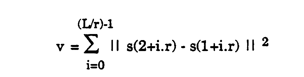
Cette variable peut encore s'écrire :


Q étant la fréquence du brouilleur (on suppose que l'on se place dans le cas d'un brouilleur à porteuse pure, et on suppose également que les termes d'intersymbole sont nuls, c'est-à-dire que l'on a : h((m-n)T)-=δmn).Q being the frequency of the jammer (it is assumed that one places oneself in the case of a jammer with pure carrier, and one also supposes that the terms of intersymbol are null, that is to say that one a: h ((mn) T) - = δ mn ).
Cette variable de décision n'est pas la seule possible, et l'invention n'est pas limitée à ce choix. En particulier, si l'on voulait privilégier la résistance au bruit plus que la résistance aux brouilleurs, on pourrait choisir une variable de décision différente, plus performante.This decision variable is not the only one possible, and the invention is not limited to this choice. In particular, if we wanted to favor noise resistance more than resistance to jammers, we could choose a different, more efficient decision variable.
L'espérance mathématique E[v] de cette variable de décision v peut être majorée de la façon suivante, No étant la densité spectrale de puissance du bruit gaussien en bande de base. :
La prise de décision (changement de séquence ou non) sera opérée par un circuit 25 effectuant la comparaison de E[v] avec un seuil correspondant à cette majoration.The decision-making (change of sequence or not) will be operated by a
Ce circuit 25 commandera le changement éventuel de séquence du circuit générateur de séquence 26, qui contient un jeu de q séquences différentes, qui sont identiques à celle contenues dans le générateur 10 de l'émetteur et qui se succèdent selon la même loi déterministe.This
De façon en elle-même connue, la séquence délivrée sera combinée en 27 aux échantillons s(kT) issus du démodulateur, les résultats de cette combinaison étant ensuite soumis à des opérations classiques de traitement numérique, régénération, etc. dans le circuit 28.In a manner known per se, the sequence delivered will be combined in 27 to the samples s (kT) coming from the demodulator, the results of this combination then being subjected to conventional operations of digital processing, regeneration, etc. in
On notera que, en variante et sans sortir du cadre de l'invention, au lieu d'utiliser pour le critère de décision la différence des modules des échantillons marqués, on pourrait utiliser la différence des phases de ces mêmes échantillons. Toutefois, une telle manière de procéder présente une moindre efficacité face aux brouilleurs.It will be noted that, as a variant and without departing from the scope of the invention, instead of using the difference of the modules of the marked samples for the decision criterion, the difference of the phases of these same samples could be used. However, such a procedure is less effective in dealing with jammers.
Également en variante, au lieu de prendre la décision en aval du module accumulateur 24, c'est-à-dire en attendant que les échantillons marqués correspondant aux L/r symboles successifs d'une même séquence aient été analysés, on peut envisager de prendre une décision intermédiaire avant sommation complète, c'est-à-dire en ne se basant que sur une partie des échantillons marqués (qui sont tous redondants) de la séquence.Also alternatively, instead of making the decision downstream of the
Claims (7)
caractérisé en ce que :
characterized in that:
émetteur caractérisé en ce qu'il comprend en outre :
transmitter characterized in that it further comprises:
récepteur caractérisé en ce qu'il comprend en outre :
receiver characterized in that it further comprises:
Applications Claiming Priority (2)
| Application Number | Priority Date | Filing Date | Title |
|---|---|---|---|
| FR9008179A FR2664113B1 (en) | 1990-06-28 | 1990-06-28 | DIRECT SEQUENCE SPREAD CHANGE DIGITAL SPREAD TRANSMISSION METHOD DURING TRANSMISSION, AND TRANSMITTER AND RECEIVER USING THE SAME. |
| FR9008179 | 1990-06-28 |
Publications (2)
| Publication Number | Publication Date |
|---|---|
| EP0470352A1 true EP0470352A1 (en) | 1992-02-12 |
| EP0470352B1 EP0470352B1 (en) | 1995-10-25 |
Family
ID=9398123
Family Applications (1)
| Application Number | Title | Priority Date | Filing Date |
|---|---|---|---|
| EP91110397A Expired - Lifetime EP0470352B1 (en) | 1990-06-28 | 1991-06-24 | Method for direct sequence spread spectrum digital transmission with sequence change during transmission and transmitter and receiver for implementing said method |
Country Status (6)
| Country | Link |
|---|---|
| US (1) | US5170410A (en) |
| EP (1) | EP0470352B1 (en) |
| CA (1) | CA2045881C (en) |
| DE (1) | DE69114075T2 (en) |
| ES (1) | ES2080194T3 (en) |
| FR (1) | FR2664113B1 (en) |
Families Citing this family (12)
| Publication number | Priority date | Publication date | Assignee | Title |
|---|---|---|---|---|
| US5353302A (en) * | 1993-02-03 | 1994-10-04 | At&T Bell Laboratories | Signal despreader for CDMA systems |
| US5341396A (en) * | 1993-03-02 | 1994-08-23 | The Boeing Company | Multi-rate spread system |
| ATE271293T1 (en) * | 1993-11-01 | 2004-07-15 | Qualcomm Inc | METHOD AND DEVICE FOR TRANSMITTING VARIABLE RATE DIGITAL DATA |
| JP2734955B2 (en) * | 1993-12-24 | 1998-04-02 | 日本電気株式会社 | Wireless data communication device |
| US5625642A (en) * | 1994-10-11 | 1997-04-29 | Lucent Technologies Inc. | Spread-response precoding system having signature sequences longer than the inter-symbol time interval |
| US5570351A (en) * | 1994-10-11 | 1996-10-29 | Lucent Technologies Inc. | Multi-user communication system employing spread signatures |
| US5574747A (en) * | 1995-01-04 | 1996-11-12 | Interdigital Technology Corporation | Spread spectrum adaptive power control system and method |
| US5960028A (en) * | 1995-08-11 | 1999-09-28 | Sharp Kabushiki Kaisha | Spread spectrum communication system |
| EP0997011B1 (en) * | 1998-05-12 | 2007-07-11 | Samsung Electronics Co., Ltd. | Device and method for reducing the peak-to-average power ratio of a mobile station's transmit power |
| FR2799072B1 (en) * | 1999-09-29 | 2001-11-02 | Mitsubishi Electric Inf Tech | METHOD FOR TRANSMITTING USER DATA AND CONTROL DATA OVER CHANNELS OF A TRANSMISSION NETWORK |
| FI20031441A0 (en) * | 2003-10-03 | 2003-10-03 | Nokia Corp | Feedback information for adjusting the transmission in the communication system |
| DE102004013884B4 (en) * | 2004-03-22 | 2006-04-27 | Deutsches Zentrum für Luft- und Raumfahrt e.V. | Protected spread spectrum signal transmission system for multiple-access messages uses pseudo-random sequences as expansion codes |
Citations (1)
| Publication number | Priority date | Publication date | Assignee | Title |
|---|---|---|---|---|
| FR2290800A1 (en) * | 1974-11-05 | 1976-06-04 | Patelhold Patentverwertung | Improved secrecy of scrambled signals transmission - uses scrambling and unscrambling control by corresponding key signals (NL040576) |
Family Cites Families (3)
| Publication number | Priority date | Publication date | Assignee | Title |
|---|---|---|---|---|
| US4285060A (en) * | 1978-02-28 | 1981-08-18 | Harris Corporation | Spread spectrum code tracking loop |
| US5063571A (en) * | 1989-12-27 | 1991-11-05 | Nynex Corporation | Method and apparatus for increasing the data rate for a given symbol rate in a spread spectrum system |
| US5025452A (en) * | 1990-03-20 | 1991-06-18 | Andrew Corporation | Full-duplex, sub-band spread spectrum communications system |
-
1990
- 1990-06-28 FR FR9008179A patent/FR2664113B1/en not_active Expired - Fee Related
-
1991
- 1991-06-24 ES ES91110397T patent/ES2080194T3/en not_active Expired - Lifetime
- 1991-06-24 EP EP91110397A patent/EP0470352B1/en not_active Expired - Lifetime
- 1991-06-24 DE DE69114075T patent/DE69114075T2/en not_active Expired - Fee Related
- 1991-06-26 US US07/721,007 patent/US5170410A/en not_active Expired - Fee Related
- 1991-06-27 CA CA002045881A patent/CA2045881C/en not_active Expired - Fee Related
Patent Citations (1)
| Publication number | Priority date | Publication date | Assignee | Title |
|---|---|---|---|---|
| FR2290800A1 (en) * | 1974-11-05 | 1976-06-04 | Patelhold Patentverwertung | Improved secrecy of scrambled signals transmission - uses scrambling and unscrambling control by corresponding key signals (NL040576) |
Non-Patent Citations (1)
| Title |
|---|
| INTERNATIONAL CONFERENCE ON COMMUNICATIONS 1980, vol. 3, juin 1980, pages 5351-5355, New York, US; R.L. PICKHOLTZ et al.: "Optimization of the processing gain of an M-ary direct sequence spread spectrum communication system" * |
Also Published As
| Publication number | Publication date |
|---|---|
| FR2664113A1 (en) | 1992-01-03 |
| CA2045881A1 (en) | 1991-12-29 |
| ES2080194T3 (en) | 1996-02-01 |
| US5170410A (en) | 1992-12-08 |
| FR2664113B1 (en) | 1993-06-04 |
| DE69114075D1 (en) | 1995-11-30 |
| EP0470352B1 (en) | 1995-10-25 |
| DE69114075T2 (en) | 1996-04-04 |
| CA2045881C (en) | 1994-12-27 |
Similar Documents
| Publication | Publication Date | Title |
|---|---|---|
| EP0610988B1 (en) | Multi-user spread spectrum communication system | |
| EP0718983B1 (en) | Differential modulation spread spectrum | |
| EP0470352B1 (en) | Method for direct sequence spread spectrum digital transmission with sequence change during transmission and transmitter and receiver for implementing said method | |
| CA2173779C (en) | Spread spectrum signal receiver | |
| FR2774831A1 (en) | ADAPTIVE SIGNAL RECEIVER FOR CULTIVATED PULTIPLE ACCESS COMMUNICATION SYSTEM | |
| EP0660559A1 (en) | Multicarrier frequency-hopping communication system | |
| FR2764143A1 (en) | METHOD FOR DETERMINING A SYMBOL TRANSMISSION FORMAT IN A TRANSMISSION SYSTEM AND SYSTEM | |
| FR2765048A1 (en) | SIGNAL MODULATION / DEMODULATION METHOD AND SYSTEM FOR IMPLEMENTING IT | |
| FR2801155A1 (en) | Multiple code division sequence communications high speed cell communication having spread sample/noisy sequences code symbol modulated and reception despreading overcoming noisy sequences/output samples producing. | |
| WO2001065789A1 (en) | Method and device for estimating channel propagation | |
| EP0917299B1 (en) | Digital direct sequence spread spectrum transmission with interference signal generation | |
| EP0820157B1 (en) | Method for digital differential demodulation | |
| EP0778677B1 (en) | Digital circuit for differential receiver of direct sequence spread spectrum signals | |
| EP0629059B1 (en) | Spread spectrum digital transmission system with low frequency pseudorandom coding of the useful information and method for spectrum spreading and compressing used in such a system | |
| EP0917298B1 (en) | Differential direct sequence spread spectrum receiver with mixed interference signal generation means | |
| EP0655845B1 (en) | Spread spectrum packet transmission system | |
| FR2888076A1 (en) | METHOD FOR AUTOMATIC CORRECTION OF SPECTRAL INVERSION IN A DEMODULATOR AND DEVICE FOR CARRYING OUT THE METHOD | |
| EP1283605A1 (en) | Method for data date increase in a communication system with N transmitters and M receivers | |
| CA2060413C (en) | Interfering signal detection method and device for a digital data demodulator | |
| EP1271818A1 (en) | System and method for the transmission of an audio or voice signal | |
| EP0911991A1 (en) | Method of spread spectrum transmission signal processing and corresponding receiver | |
| FR2691309A1 (en) | Despreading method in reception of a broadband signal | |
| FR2782426A1 (en) | SPECTRUM SPREADING OR DESSETTING DEVICE, ESPECIALLY FOR TRANSMISSION IN A MOBILE RADIOCOMMUNICATION CELL SYSTEM OF THE MULTIPLE ACCESS TYPE BY CODES DISTRIBUTION | |
| EP1573933B1 (en) | Method and system for receiving an ultra-wideband signal with a self-adapting number of propagation paths | |
| WO2005109708A1 (en) | Method for determination of code spread used in a cdma signal and corresponding communication device |
Legal Events
| Date | Code | Title | Description |
|---|---|---|---|
| PUAI | Public reference made under article 153(3) epc to a published international application that has entered the european phase |
Free format text: ORIGINAL CODE: 0009012 |
|
| AK | Designated contracting states |
Kind code of ref document: A1 Designated state(s): CH DE ES FR GB IT LI NL SE |
|
| RAP1 | Party data changed (applicant data changed or rights of an application transferred) |
Owner name: ALCATEL N.V. Owner name: ALCATEL TELSPACE |
|
| 17P | Request for examination filed |
Effective date: 19920803 |
|
| 17Q | First examination report despatched |
Effective date: 19940708 |
|
| GRAA | (expected) grant |
Free format text: ORIGINAL CODE: 0009210 |
|
| AK | Designated contracting states |
Kind code of ref document: B1 Designated state(s): CH DE ES FR GB IT LI NL SE |
|
| REF | Corresponds to: |
Ref document number: 69114075 Country of ref document: DE Date of ref document: 19951130 |
|
| ITF | It: translation for a ep patent filed |
Owner name: JACOBACCI & PERANI S.P.A. |
|
| GBT | Gb: translation of ep patent filed (gb section 77(6)(a)/1977) |
Effective date: 19951216 |
|
| REG | Reference to a national code |
Ref country code: ES Ref legal event code: FG2A Ref document number: 2080194 Country of ref document: ES Kind code of ref document: T3 |
|
| PG25 | Lapsed in a contracting state [announced via postgrant information from national office to epo] |
Ref country code: LI Effective date: 19960630 Ref country code: CH Effective date: 19960630 |
|
| PLBE | No opposition filed within time limit |
Free format text: ORIGINAL CODE: 0009261 |
|
| STAA | Information on the status of an ep patent application or granted ep patent |
Free format text: STATUS: NO OPPOSITION FILED WITHIN TIME LIMIT |
|
| 26N | No opposition filed | ||
| REG | Reference to a national code |
Ref country code: CH Ref legal event code: PL |
|
| PGFP | Annual fee paid to national office [announced via postgrant information from national office to epo] |
Ref country code: GB Payment date: 20010515 Year of fee payment: 11 |
|
| PGFP | Annual fee paid to national office [announced via postgrant information from national office to epo] |
Ref country code: SE Payment date: 20010531 Year of fee payment: 11 Ref country code: FR Payment date: 20010531 Year of fee payment: 11 |
|
| PGFP | Annual fee paid to national office [announced via postgrant information from national office to epo] |
Ref country code: DE Payment date: 20010611 Year of fee payment: 11 |
|
| PGFP | Annual fee paid to national office [announced via postgrant information from national office to epo] |
Ref country code: ES Payment date: 20010614 Year of fee payment: 11 |
|
| PGFP | Annual fee paid to national office [announced via postgrant information from national office to epo] |
Ref country code: NL Payment date: 20010618 Year of fee payment: 11 |
|
| REG | Reference to a national code |
Ref country code: GB Ref legal event code: IF02 |
|
| PG25 | Lapsed in a contracting state [announced via postgrant information from national office to epo] |
Ref country code: GB Free format text: LAPSE BECAUSE OF NON-PAYMENT OF DUE FEES Effective date: 20020624 |
|
| PG25 | Lapsed in a contracting state [announced via postgrant information from national office to epo] |
Ref country code: SE Free format text: LAPSE BECAUSE OF NON-PAYMENT OF DUE FEES Effective date: 20020625 Ref country code: ES Free format text: LAPSE BECAUSE OF NON-PAYMENT OF DUE FEES Effective date: 20020625 |
|
| PG25 | Lapsed in a contracting state [announced via postgrant information from national office to epo] |
Ref country code: NL Free format text: LAPSE BECAUSE OF NON-PAYMENT OF DUE FEES Effective date: 20030101 Ref country code: DE Free format text: LAPSE BECAUSE OF NON-PAYMENT OF DUE FEES Effective date: 20030101 |
|
| EUG | Se: european patent has lapsed | ||
| GBPC | Gb: european patent ceased through non-payment of renewal fee |
Effective date: 20020624 |
|
| PG25 | Lapsed in a contracting state [announced via postgrant information from national office to epo] |
Ref country code: FR Free format text: LAPSE BECAUSE OF NON-PAYMENT OF DUE FEES Effective date: 20030228 |
|
| NLV4 | Nl: lapsed or anulled due to non-payment of the annual fee |
Effective date: 20030101 |
|
| REG | Reference to a national code |
Ref country code: FR Ref legal event code: ST |
|
| REG | Reference to a national code |
Ref country code: ES Ref legal event code: FD2A Effective date: 20030711 |
|
| PG25 | Lapsed in a contracting state [announced via postgrant information from national office to epo] |
Ref country code: IT Free format text: LAPSE BECAUSE OF NON-PAYMENT OF DUE FEES;WARNING: LAPSES OF ITALIAN PATENTS WITH EFFECTIVE DATE BEFORE 2007 MAY HAVE OCCURRED AT ANY TIME BEFORE 2007. THE CORRECT EFFECTIVE DATE MAY BE DIFFERENT FROM THE ONE RECORDED. Effective date: 20050624 |