EP0470342A1 - Membrane pump - Google Patents
Membrane pump Download PDFInfo
- Publication number
- EP0470342A1 EP0470342A1 EP91109443A EP91109443A EP0470342A1 EP 0470342 A1 EP0470342 A1 EP 0470342A1 EP 91109443 A EP91109443 A EP 91109443A EP 91109443 A EP91109443 A EP 91109443A EP 0470342 A1 EP0470342 A1 EP 0470342A1
- Authority
- EP
- European Patent Office
- Prior art keywords
- membrane
- diaphragm pump
- diaphragm
- pump according
- signal
- Prior art date
- Legal status (The legal status is an assumption and is not a legal conclusion. Google has not performed a legal analysis and makes no representation as to the accuracy of the status listed.)
- Withdrawn
Links
Images


Classifications
-
- F—MECHANICAL ENGINEERING; LIGHTING; HEATING; WEAPONS; BLASTING
- F04—POSITIVE - DISPLACEMENT MACHINES FOR LIQUIDS; PUMPS FOR LIQUIDS OR ELASTIC FLUIDS
- F04B—POSITIVE-DISPLACEMENT MACHINES FOR LIQUIDS; PUMPS
- F04B43/00—Machines, pumps, or pumping installations having flexible working members
- F04B43/0009—Special features
- F04B43/0081—Special features systems, control, safety measures
- F04B43/009—Special features systems, control, safety measures leakage control; pump systems with two flexible members; between the actuating element and the pumped fluid
Definitions
- the invention relates to a diaphragm pump with a diaphragm clamped in its outer edge region in a pump housing and drivable in an oscillating manner by a hydraulic medium, through which a delivery chamber of the diaphragm pump is separated from a drive chamber receiving the hydraulic medium, the diaphragm consisting of two with an axial spacing from one another arranged, an interior enclosing membrane disks is assembled, the size of which can be changed if one of the membrane disks is damaged.
- the line part connecting the space between the individual membranes to the storage container has, at least in the clamping area of the membrane that is pressure-tight by 250 bar, only a very narrow to capillary passage cross section. In the case of a conveying medium which is particularly provided with solid particles, this line part clogs very easily, which leads to the failure of the flow indicator function.
- the object of the invention is therefore to design a diaphragm pump of the aforementioned type in such a way that any damage to the diaphragm can be recognized at an early stage and that, in addition, hydraulic medium is reliably prevented from entering the delivery medium.
- the construction effort required for this should be kept low, but there should still be a high sensitivity and a low susceptibility to interference when monitoring the membrane.
- a diaphragm pump of the aforementioned type which has a membrane composed of two diaphragm disks arranged at an axial distance from one another and enclosing an interior, the size of the interior being changeable if one of the diaphragm disks is damaged, in that the Conveying chamber facing membrane disc, a signal generator and a signal sensor are arranged in the pump housing in the area of the drive chamber, which is connected to a device for electronic evaluation and amplification of the signals emitted by the signal sensor.
- the diaphragm pump it is furthermore expedient to fill the interior of the diaphragm gas-free with an incompressible, preferably with a medium compatible with the conveying medium, for example with water, a dilution or the like, and / or to provide it with a vacuum so that the two diaphragm disks oscillate synchronously with one another in the intact state, but if there is a crack in one of the diaphragm disks, their axial distance from one another and / or from the signal pickup is changed by penetration of the delivery medium or the hydraulic medium.
- an incompressible preferably with a medium compatible with the conveying medium, for example with water, a dilution or the like, and / or to provide it with a vacuum so that the two diaphragm disks oscillate synchronously with one another in the intact state, but if there is a crack in one of the diaphragm disks, their axial distance from one another and / or from the signal pickup is changed by penetration
- an axially directed, prestressed compression spring can additionally be inserted into the interior of the membrane, preferably centrally.
- the signal generator is formed by a high-energy magnet, preferably made of a samarium-cobalt alloy.
- the signal transmitter centrally into the membrane disk facing the delivery chamber, preferably in a thickened portion formed thereon, the latter being injected into the membrane disk or inserted into a recess in the membrane disk and by ultrasonic or hot air welding by gluing, by pressing or the like. Can be firmly connected to this.
- the signal pickup can be designed as a magnetoristic magnetic field sensor and, in order to generate a permanent magnetic bias field for stabilization, can be provided with a magnetic disc which is preferably arranged on the side facing away from the signal transmitter.
- the signal pickup in a closed cylinder, preferably made of a non-ferromagnetic material, for example titanium, which should be inserted in the pump housing so as to be radially adjustable to the axis of the membrane.
- a diaphragm pump according to the invention is formed in which the diaphragm is composed of two diaphragm disks, one of which has a signal transmitter which interacts with a fixedly arranged signal pickup, it is possible to operate the diaphragm in a very simple manner but nevertheless extremely reliably monitor and detect any damage to one of the two diaphragm disks at an early stage. If crack formation or breakage occurs in one of the diaphragm disks, at least one of the end positions of the diaphragm disk carrying the signal transmitter changes immediately in relation to the signal pickup, since the stored medium flows out of the double-walled diaphragm and medium is sucked into it or introduced under pressure.
- this change in position can be detected and evaluated by a signal pickup, so that cracking in one of the membrane disks can already be detected. If the diaphragm disc facing the delivery chamber is damaged, the diaphragm pump will still be operational and no immediate interruption in operation is acceptable. Rather, the damaged membrane may be at an appropriate time, e.g. B. after the end of day work, without a major business interruption occurs.
- the diaphragm disc facing the drive chamber is damaged, the space between the two diaphragm discs is filled with hydraulic medium; as a result, the diaphragm disk facing the delivery chamber is pressed into its upper end position, with the result that the pump no longer delivers.
- the diaphragm pump 1 essentially consists of a driven diaphragm 21 clamped between two housing parts 2 and 3 provided with contact disks 4 and 5, by means of which a working chamber 6 is separated from a delivery chamber 7.
- a working chamber 6 is separated from a delivery chamber 7.
- the piston 11 acts on the membrane 21 via a liquid column located in the pressure chamber 6.
- the system disc 4 is provided with holes 14 through which a space 13 between the membrane 21 and the disc 4 is thus connected to the working chamber 6.
- Via a suction line 16 the working chamber 6 is connected to a storage container 15, to which a return line 17, into which a pressure relief valve, not shown, is used to reduce pressure peaks, is connected.
- a suction stroke the medium to be conveyed is sucked into the delivery chamber 7 via a suction line 8, which is equipped with an inlet valve 9, and in a pressure line 10, which is of course also equipped with a check valve (not shown), during a pressure stroke with the inlet valve 9 closed. promoted.
- the membrane 21, as can be seen in detail in FIG. 3, consists of two membrane disks 22 and 23 arranged at an axial distance from one another, which thus enclose an interior space 24 and each have a central thickening 26 and 27 and, following an outer clamping area, a Walk zone 29 and 30 have.
- a prestressed compression spring 25 is inserted into the interior 24, which in the exemplary embodiment shown is filled with a gas-free incompressible liquid which is compatible with the medium to be conveyed.
- a signal transmitter 31 preferably in the form of a high-energy magnet
- a signal pickup 32 which is matched to this is inserted into the housing part 2 and is connected via a signal line 33 to an electronic device 34 is connected to the evaluation and amplification of the signals emitted by the signal pickup 31.
- the signals can be evaluated and amplified in such a way that they can be used as optical and / or acoustic signals and / or for switching off the diaphragm pump 1.
- the high-pressure pump 1 can thus be taken out of operation before the diaphragm 21 is damaged in such a way that the hydraulic medium in the working chamber 6 reaches the delivery chamber 7. Long downtimes and larger rejects can thus be reliably avoided.
- the signal pickup 32 according to FIG. 3 can be equipped with a magnetic plate 35 on the side facing away from the membrane disk 23, by means of which the signal pickup 32 designed as a magnetic field sensor is stabilized.
- the signal pickup 32 is cast in a cylinder 36 made of a non-ferromagnetic material, for example titanium, which is in a bore 37 in the housing part 2 and - in the embodiment according to FIG. 3 - the contact disk 4 is used.
- a threaded bushing 38 With the aid of a threaded bushing 38, the cylinder 36, through which the signal sensor 32 is thus protected from pressurization by the hydraulic medium in the working chamber 6, can be adjusted radially to the axis of the diaphragm 21, so that the signal sensor 32 is aligned perpendicular to the signal sensor 31 can.
Abstract
Description
Die Erfindung bezieht sich auf eine Membranpumpe mit einer in ihrem äußeren Randbereich in einem Pumpengehäuse eingespannten und durch ein hydraulisches Medium oszillierend antreibbaren Membran, durch die eine Förderkammer der Membranpumpe von einer das Hydraulikmedium aufnehmenden Antriebskammer getrennt ist, wobei die Membran aus zwei mit axialem Abstand zueinander angeordneten, einen Innenraum einschließenden Membranscheiben zusammengesetzt ist, dessen Größe bei Beschädigung einer der Membranscheiben veränderbar ist.The invention relates to a diaphragm pump with a diaphragm clamped in its outer edge region in a pump housing and drivable in an oscillating manner by a hydraulic medium, through which a delivery chamber of the diaphragm pump is separated from a drive chamber receiving the hydraulic medium, the diaphragm consisting of two with an axial spacing from one another arranged, an interior enclosing membrane disks is assembled, the size of which can be changed if one of the membrane disks is damaged.
Um bei einer Membranpumpe eine etwaige Beschädigung der Membran erkennen zu können, ist es durch die DE-A-18 00 018 bekannt, die Membran aus mehreren, biespielsweise aus drei aneinander anliegenden Einzelmembrane zusammenzusetzen, und den Raum zwischen den Einzelmembranen vollkommen mit Hydraulikmedium zu füllen und über eine mit einem Rückschlagventil ausgestattete Leitung an einen Vorratsbehälter anzuschliessen. Bei einem Bruch einer der beiden äußeren Membrane kann somit das zu fördernde Medium aus der Förderkammer oder das Hydraulikmedium aus der Arbeitskammer in den Vorratsbehälter einströmen und dadurch die Anzeigevorrichtung auslösen.In order to be able to detect any damage to the membrane in a diaphragm pump, it is known from DE-A-18 00 018 to assemble the diaphragm from several, for example three, individual diaphragms lying against one another, and to completely fill the space between the individual diaphragms with hydraulic medium and to be connected to a storage container via a line equipped with a check valve. If one of the two outer membranes breaks, the medium to be pumped can flow from the delivery chamber or the hydraulic medium from the working chamber into the reservoir and thereby trigger the display device.
Der den Raum zwischen den Einzelmembranen mit dem Vorratsbehäler verbindende Leitungsteil weist, zumindest im um 250 bar druckdichten Einspannbereich der Membrane, nur einen sehr engen bis kapillaren Durchgangsquerschnitt auf. Bei besonders mit Feststoffpartikeln versehenem Fördermedium setzt sich dieser Leitungsteil somit sehr leicht zu, dies führt zum Ausfall der Funktion der Strömungsanzeige.The line part connecting the space between the individual membranes to the storage container has, at least in the clamping area of the membrane that is pressure-tight by 250 bar, only a very narrow to capillary passage cross section. In the case of a conveying medium which is particularly provided with solid particles, this line part clogs very easily, which leads to the failure of the flow indicator function.
Abgesehen davon, daß der Bauaufwand bei dieser Ausgestaltung erheblich und die Anzeigevorrichtung äußerst unempfindlich ist, da diese auf eine Niveauänderung des Hydraulikmediums im Vorratsbehälter anspricht, ist des weiteren vor allem von Nachteil, daß bei einer Beschädigung der der Förderkammer zugekehrten Einzelmembran eine relativ große Menge des in dem Raum zwischen den Membranen und der diesen mit dem Vorratsbehälter verbindenden Leitung befindlichen Hydraulikmediums aus diesen in das geförderte Medium gelangt. Dies kann zu erheblichen Ausfallzeiten sowie zu einer Ausschußproduktion führen, so daß der reibungslose Ablauf einer kontinuierlichen Fertigung sehr beeinträchtigt wird. In Farbspritzgeräten beispielsweise ist diese Art der Membranbruchüberwachung daher nicht einsetzbar, zumal eine Brucherkennung erst möglich ist, wenn eine der beiden äußeren Membrane derart beschädigt ist, daß Förder- oder Hydraulikmedium zusätzlich in die der Anzeigevorrichtung zugeordneten Bauteile gelangt.Apart from the fact that the construction effort in this embodiment is considerable and the display device is extremely insensitive, since it responds to a change in the level of the hydraulic medium in the reservoir, a further disadvantage is that a relatively large amount of the damage to the individual diaphragm facing the delivery chamber in the space between the diaphragms and the hydraulic medium located connecting them to the reservoir from them reaches the conveyed medium. This can lead to considerable downtimes and to rejects, so that the smooth running of a continuous production is very impaired. This type of membrane breakage monitoring, for example, cannot therefore be used in paint spraying devices, especially since breakage detection is only possible if one of the two outer membranes is damaged in such a way that the conveying or hydraulic medium additionally gets into the components assigned to the display device.
Aufgabe der Erfindung ist es daher, eine Membranpumpe der vorgenannten Gattung in der Weise auszugestalten, daß eine etwaige Beschädigung der Membran frühzeitig erkennbar ist und daß außerdem zuverlässig verhindert wird, daß Hydraulikmedium in das Fördermedium gelangt. Der dazu erforderliche Bauaufwand soll gering gehalten werden, dennoch soll eine hohe Empfindlichkeit und eine geringe Störanfälligkeit bei der Überwachung der Membran gegeben sein.The object of the invention is therefore to design a diaphragm pump of the aforementioned type in such a way that any damage to the diaphragm can be recognized at an early stage and that, in addition, hydraulic medium is reliably prevented from entering the delivery medium. The construction effort required for this should be kept low, but there should still be a high sensitivity and a low susceptibility to interference when monitoring the membrane.
Gemäß der Erfindung wird dies bei einer Membranpumpe der vorgenannten Gattung, die eine aus zwei mit axialem Abstand zueinander angeordneten, einen Innenraum einschließende Membranscheiben zusammengesetzte Membran aufweist, wobei die Größe des Innenraumes bei Beschädigung einer der Membranscheiben veränderbar ist, dadurch erreicht, daß in der der Förderkammer zugekehrten Membranscheibe ein Signalgeber und in das Pumpengehäuse im Bereich der Antriebskammer ein Signalaufnehmer angeordnet sind, der an eine Einrichtung zur elektronischen Auswertung und Verstärkung der von dem Signalaufnehmer abgegebenen Signale angeschlossen ist.According to the invention, this is achieved in a diaphragm pump of the aforementioned type which has a membrane composed of two diaphragm disks arranged at an axial distance from one another and enclosing an interior, the size of the interior being changeable if one of the diaphragm disks is damaged, in that the Conveying chamber facing membrane disc, a signal generator and a signal sensor are arranged in the pump housing in the area of the drive chamber, which is connected to a device for electronic evaluation and amplification of the signals emitted by the signal sensor.
Durch die DE-A-26 24 129 sowie die US-A-49 34 902 sind zwar bereits elektrische bzw. magnetische Verfahren zur Signalisierung eines Membranbruches bei einer Magnetpumpe bekannt, einen Signalgeber in der der Förderkammer zugekehrten Membranscheibe und einen Signalaufnehmer im Bereich der Antriebskammer anzuordnen, ist bei diesen Ausgestaltungen jedoch nicht vorgesehen.From DE-A-26 24 129 and US-A-49 34 902 electrical or magnetic methods for signaling a diaphragm rupture in a magnetic pump are already known, a signal transmitter in the diaphragm disc facing the delivery chamber and a signal sensor in the area of the drive chamber to arrange, however, is not provided in these configurations.
Bei der erfindungsgemäßen Membranpumpe ist es des weiteren zweckmäßig, den Innenraum der Membran gasfrei mit einem inkompresiblen, vorzugsweise mit einem mit dem Fördermedium verträglichen Medium, beispielsweise mit Wasser, einer Verdünnung oder dgl., auszufüllen und/oder mit einem Unterdruck zu versehen, so daß die beiden Membranscheiben in intaktem Zustand synchron miteinander oszillieren, bei einer Rißbildung in einer der Membranscheiben aber deren axialer Abstand zueinander und/oder zu dem Signalaufnehmer durch Eindringen des Fördermediums oder des Hydraulikmediums verändert wird.In the diaphragm pump according to the invention it is furthermore expedient to fill the interior of the diaphragm gas-free with an incompressible, preferably with a medium compatible with the conveying medium, for example with water, a dilution or the like, and / or to provide it with a vacuum so that the two diaphragm disks oscillate synchronously with one another in the intact state, but if there is a crack in one of the diaphragm disks, their axial distance from one another and / or from the signal pickup is changed by penetration of the delivery medium or the hydraulic medium.
Um in einem solchen Fall die Lageänderung zu unterstützen, kann zusätzlich in den Innenraum der Membran, vorzugsweise zentrisch, eine axial gerichtete vorgespannte Druckfeder eingesetzt sein.In order to support the change of position in such a case, an axially directed, prestressed compression spring can additionally be inserted into the interior of the membrane, preferably centrally.
Der Signalgeber wird durch einen Hochenergiemagneten, vorzugsweise aus einer Samarium-Kobalt-Legierung, gebildet.The signal generator is formed by a high-energy magnet, preferably made of a samarium-cobalt alloy.
Angebracht ist es ferner, den Signalgeber mittig in die der Förderkammer zugekehrten Membranscheibe, vorzugsweise in einer an dieser angeformten Verdickung, einzusetzen, wobei dieser in die Membranscheibe eingespritzt oder in einer Ausnehmung der Membranscheibe eingesetzt und durch eine Ultraschall- oder Heißluftschweißung durch Verkleben, durch Pressung oder dgl. mit dieser fest verbunden sein kann.It is also appropriate to insert the signal transmitter centrally into the membrane disk facing the delivery chamber, preferably in a thickened portion formed thereon, the latter being injected into the membrane disk or inserted into a recess in the membrane disk and by ultrasonic or hot air welding by gluing, by pressing or the like. Can be firmly connected to this.
Der Signalaufnehmer kann als magnetoristischer Magnetfeldsensor ausgebildet und zur Erzeugung eines permantentmagnetischen Vorspannfeldes zur Stabilisierung mit einem vorzugsweise auf der dem Signalgeber abgekehrten Seite angeordneten Magnetblättchen versehen sein.The signal pickup can be designed as a magnetoristic magnetic field sensor and, in order to generate a permanent magnetic bias field for stabilization, can be provided with a magnetic disc which is preferably arranged on the side facing away from the signal transmitter.
Vorteilhaft ist es ferner, den Signalaufnehmer in einem geschlossenen Zylinder, vorzugsweise aus einem nichtferromagnetischen Werkstoff, beispielsweise Titan, anzuordnen, der zur Achse der Membran radial verstellbar in dem Pumpengehäuse eingesetzt sein sollte.It is also advantageous to arrange the signal pickup in a closed cylinder, preferably made of a non-ferromagnetic material, for example titanium, which should be inserted in the pump housing so as to be radially adjustable to the axis of the membrane.
Die beiden Membranscheiben sollten in ihrem äußeren Randbereich durch Verkleben, durch Ultraschall- oder Heißluftverschweißung oder in ähnlicher Weise fest miteinander verbunden sein.The two membrane disks should be firmly connected to one another in their outer edge region by gluing, by ultrasonic welding or hot air welding or in a similar manner.
Wird eine Membranpumpe gemäß der Erfindung ausgebildet, in dem die Membran aus zwei Membranscheiben zusammengesetzt wird, von denen eine einen Signalgeber aufweist, der mit einem ortsfest angeordneten Signalaufnehmer zusammenwirkt, so ist es möglich, den Betriebszustand der Membran auf sehr einfache Weise aber dennoch äußerst zuverlässig zu überwachen und eine etwaige Beschädigung einer der beiden Membranscheiben frühzeitig zu erkennen. Tritt nämlich in einer der Membranscheiben eine Rißbildung oder ein Bruch auf, so verändert sich sofort zumindest eine der Endlagen der den Signalgeber tragenden Membranscheibe gegenüber dem Signalaufnehmer, da das eingelagerte Medium aus der doppelwandigen Membran ausströmt und Medium in diese eingesaugt oder unter Druck eingebracht wird. Und diese Lageänderung kann durch einen Signalaufnehmer detektiert und ausgewertet werden, so daß bereits eine Rißbildung in einer der Membranscheiben erkannt werden kann. Wird die der Förderkammer zugewandte Membranscheibe beschädigt, bleibt die Membranpumpe aber dennoch betriebsfähig und keine unmittelbare Betriebsunterbrechung ist in Kauf zu nehmen. Die beschädigte Membran kann vielmehr zu einem geeigneten Zeitpunkt, z. B. nach Beendigung der Tagesarbeit, ohne daß eine größere Betriebsunterbrechung auftritt, ausgetauscht werden.If a diaphragm pump according to the invention is formed in which the diaphragm is composed of two diaphragm disks, one of which has a signal transmitter which interacts with a fixedly arranged signal pickup, it is possible to operate the diaphragm in a very simple manner but nevertheless extremely reliably monitor and detect any damage to one of the two diaphragm disks at an early stage. If crack formation or breakage occurs in one of the diaphragm disks, at least one of the end positions of the diaphragm disk carrying the signal transmitter changes immediately in relation to the signal pickup, since the stored medium flows out of the double-walled diaphragm and medium is sucked into it or introduced under pressure. And this change in position can be detected and evaluated by a signal pickup, so that cracking in one of the membrane disks can already be detected. If the diaphragm disc facing the delivery chamber is damaged, the diaphragm pump will still be operational and no immediate interruption in operation is acceptable. Rather, the damaged membrane may be at an appropriate time, e.g. B. after the end of day work, without a major business interruption occurs.
Wird die der Antriebskammer zugewandte Membranscheibe beschädigt, füllt sich der Raum zwischen beiden Membranscheiben mit Hydraulikmedium; dadurch wird die der Förderkammer zugewandte Membranscheibe in ihre obere Endlage gedrückt, mit dem Resultat, daß die Pumpe nicht mehr fördert.If the diaphragm disc facing the drive chamber is damaged, the space between the two diaphragm discs is filled with hydraulic medium; as a result, the diaphragm disk facing the delivery chamber is pressed into its upper end position, with the result that the pump no longer delivers.
Da die Membran, durch die die Förderkammer von der Antriebskammer getrennt ist, doppelwandig ist, kann demnach auch bei einem Leck in einer der Membranscheiben kein Hydraulikmedium in die Förderkammer und umgekehrt gelangen. Beim Einsatz einer derartigen Membranpumpe in einem Farbspritzgerät ist somit die Farbstufe und das zu beschichtende Objekt mit Sicherheit vor einer Verschmutzung durch Hydraulikmedium gesichert, da der Innenraum der Membran mit einer mit dem zu fördernden Medium verträglichen Flüssigkeit ausgefüllt werden kann. Eine Ausschußfertigung wird somit, auch bei einem Bruch der der Förderkammer zugekehrten Membranscheibe, weitgehend vermieden. Und da trotz des geringen Bauaufwandes nicht nur eine zuverlässige Früherkennung, sondern auch eine hohe Empfindlichkeit bei dem vorschlagsgemäß ausgebildeten Erkennungssystem gewährleistet sind, ist ein wirtschaftlicher und sehr vielseitiger Einsatz gegeben.Since the membrane through which the delivery chamber is separated from the drive chamber is double-walled, even if there is a leak in one of the membrane disks, no hydraulic medium can get into the delivery chamber and vice versa. When such a diaphragm pump is used in a paint spraying device, the paint level and the object to be coated are thus reliably protected against contamination by hydraulic medium, since the interior of the diaphragm can be filled with a liquid which is compatible with the medium to be conveyed. Reject production is thus largely avoided, even if the membrane disk facing the delivery chamber breaks. And since in spite of the low construction effort not only reliable early detection but also a high sensitivity with the detection system designed according to the proposal are guaranteed, it is economical and very versatile to use.
In der Zeichnung ist ein Ausführungsbeispiel der gemäß der Erfindung ausgebildeten Membranpumpe dargestellt, das nachfolgend im einzelnen erläutert ist. Hierbei zeigt:
- Figur 1 eine mit einer doppelwandigen Membran bestückte Hochdruckpumpe, teilweise im Schnitt,
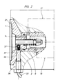
Figur 2 den bei der Hochdruckpumpe nach Figur 1 vorgesehenen Signalaufnehmer, in einem Ausschnitt, undFigur 3 die Membran mit Anlagescheibe nach Figur 1 als Einzelteil, in einem Schnitt, jedoch in abgeänderter Anordnung des Signalaufnehmers.
- 1 shows a high-pressure pump equipped with a double-walled membrane, partly in section,
- 2 shows the signal sensor provided in the high-pressure pump according to FIG. 1, in a detail, and
- Figure 3 shows the membrane with contact disc according to Figure 1 as a single part, in a section, but in a modified arrangement of the signal sensor.
Die Membranpumpe 1 nach Figur 1 besteht im wesentlichen aus einer zwischen zwei mit Anlagescheiben 4 bzw. 5 versehenen Gehäuseteilen 2 und 3 eingespannten angetriebenen Membran 21, durch die eine Arbeitskammer 6 von einer Förderkammer 7 getrennt ist. Zum Antrieb der Membran 21 dient hierbei ein in einem Zylinder 12 verschiebbar eingesetzter Kolben 11, der von einem nicht gezeigten Antriebsmittel, z. B. einem Exzenter, angetrieben wird. Über eine Flüssigkeitssäule, die sich in dem Druckraum 6 befindet, wirkt der Kolben 11 auf die Membran 21 ein. Zu diesem Zweck ist die Anlagenscheibe 4 mit Bohrungen 14 versehen, durch die somit ein Raum 13 zwischen der Membran 21 und der Scheibe 4 mit der Arbeitskammer 6 verbunden ist. Über eine Saugleitung 16 ist die Arbeitskammer 6 mit einem Vorratsbehälter 15 verbunden, an den auch eine Rücklaufleitung 17, in die zum Abbau von Druckspitzen ein nicht dargestelltes Überdruckventil eingesetzt ist, angeschlossen ist.The diaphragm pump 1 according to FIG. 1 essentially consists of a driven
An der Membran 21 ist ein mit einem Gewindeabschnitt versehener Schaft 28 angeformt, auf den eine Mutter 19 aufgeschraubt ist. Und zwischen der Anlagescheibe 4 und der Mutter 19 ist eine Druckfeder 18 eingesetzt, durch die die Membran 21 somit stets in die Ausgangslage zurückgedrückt wird, in der diese an der Anlagescheibe 4 anliegt. Bei einem Saughub wird über eine Saugleitung 8, die mit einem Einlaßventil 9 ausgestattet ist, das zu fördernde Medium in die Förderkammer 7 gesaugt und bei einem Druckhub bei geschlossenem Einlaßventil 9 in eine Druckleitung 10, die selbstverständlich auch mit einem nicht dargestellten Rückschlagventil ausgestattet ist, gefördert.A
Die Membran 21 besteht, wie dies im einzelnen der Figur 3 zu entnehmen ist, aus zwei mit axialem Abstand zueinander angeordneten Membranscheiben 22 und 23, die somit einen Innenraum 24 einschließen und jeweils eine zentrische Verdickung 26 und 27 sowie im Anschluß an einen äußeren Einspannbereich eine Walkzone 29 und 30 aufweisen. Außerdem ist in den Innenraum 24, der bei dem gezeigten Ausführungsbeispiel mit einer gasfreien inkompressiblen und mit dem zu fördernden Medium verträglichen Flüssigkeit ausgefüllt ist, eine vorgespannte Druckfeder 25 eingesetzt.The
Wird eine der beiden Membranscheiben 22 oder 23 beschädigt, so wird das zwischen diesen befindliche Medium entweder in die Arbeitskammer 6 oder in die Förderkammer 7 ausströmen, gleichzeitig aber Medium aus einer dieser Kammern in den Innenraum 24 unter Druck einströmen. Dies bewirkt aber, zumal durch die vorgespannte Feder 25 die Membranscheiben 22 und 23 in diesem Betriebszustand auseinandergedrückt werden, daß die Membranscheibe 22 bei einem Saughub nicht mehr in die ihr zugeordnete Endlage gelangt. Und diese Endlagenänderung wird ausgenutzt, um eine Beschädigung einer der Membranscheiben 22 oder 23 zu erkennen.If one of the two
Dies wird in der Weise bewerkstelligt, daß in die Verdickung 26 der Membranscheibe 22 ein Signalgeber 31, vorzugsweise in Form eines Hochenergiemagneten, eingebaut und in das Gehäuseteil 2 ein auf diesen abgestimmter Signalaufnehmer 32 eingesetzt sind, der über eine Signalleitung 33 an eine elektronische Einrichtung 34 zur Auswertung und Verstärkung der von dem Signalaufnehmer 31 abgegebenen Signale angeschlossen ist. Mittels der Einrichtung 34 können die Signale derart ausgewertet und verstärkt werden, daß diese als optische und/oder akustische Signale und/oder zur Abschaltung der Membranpumpe 1 verwertbar sind. Bei einer Fehlermeldung kann somit die Hochdruckpumpe 1 außer Betrieb genommen werden, bevor die Membran 21 derart beschädigt ist, daß das in der Arbeitskammer 6 befindliche Hydraulikmedium in die Förderkammer 7 gelangt. Lange Ausfallzeiten und größere Ausschußproduktionen können somit zuverlässig vermieden werden.This is accomplished in such a way that a
Zur Erzeugung eines permanentmagnetischen Vorspannfeldes kann der Signalaufnehmer 32 gemäß Figur 3 auf der der Membranscheibe 23 abgekehrten Seite mit einem Magnetblättchen 35 ausgestattet, durch das der als Magnetfeldsensor ausgebildete Signalaufnehmer 32 stabilisiert wird.To generate a permanent magnetic bias field, the
Der Signalaufnehmer 32 ist, wie dies der Figur 2 entnommen werden kann, in einem Zylinder 36 aus einem nicht-ferromagnetischen Werkstoff, beispielsweise Titan, vergossen, der in eine Bohrung 37 des Gehäuseteils 2 und - bei der Ausgestaltung nach Figur 3 - der Anlagescheibe 4 eingesetzt ist. Mit Hilfe einer Gewindebuchse 38 ist der Zylinder 36. durch den der Signalaufnehmer 32 somit von einer Druckbeaufschlagung durch das in der Arbeitskammer 6 befindliche Hydraulikmedium geschützt ist, radial zur Achse der Membran 21 verstellbar, so daß der Signalaufnehmer 32 achssenkrecht zu dem Signalaufnehmer 31 ausgerichtet werden kann.As can be seen in FIG. 2, the
Claims (11)
dadurch gekennzeichnet,
daß in der der Förderkammer (7) zugekehrten Membranscheibe (22) ein Signalgeber (31) und in das Pumpengehäuse (2) im Bereich der Antriebskammer (6) ein Signalaufnehmer (32) angeordnet sind, der an eine Einrichtung (34) zur elektronischen Auswertung und Verstärkung der von dem Signalaufnehmer (32) abgegebenen Signale angeschlossen ist.1.Diaphragm pump with a diaphragm clamped in its outer edge area in a pump housing and drivable oscillatingly by a hydraulic medium, through which a delivery chamber of the diaphragm pump is separated from a drive chamber which receives the hydraulic medium, the diaphragm consisting of two interior spaces arranged at an axial distance from one another including membrane disks, the size of which can be changed if one of the membrane disks is damaged,
characterized,
that a signal transmitter (31) is arranged in the diaphragm disk (22) facing the delivery chamber (7) and a signal sensor (32) is arranged in the pump housing (2) in the area of the drive chamber (6), which is connected to a device (34) for electronic evaluation and amplification of the signals emitted by the signal pickup (32) is connected.
dadurch gekennzeichnet,
daß der Innenraum (24) der Membran (21) gasfrei mit einem inkompressiblem, vorzugsweise auf einem mit dem Fördermedium verträglichen Medium, beispielsweise mit Wasser, einer Verdünnung od.dgl., ausgefüllt ist.2. diaphragm pump according to claim 1,
characterized,
that the interior (24) of the membrane (21) is filled gas-free with an incompressible, preferably on a medium compatible with the conveying medium, for example with water, a dilution or the like.
dadurch gekennzeichnet,
daß der Innenraum (24) der Membran (21) mit einem Unterdruck versehen ist. 4. Membranpumpe nach einem oder mehreren der Ansprüche 1 bis 3,
dadurch gekennzeichnet,
daß in den Innenraum (24) der Membran (21), vorzugsweise zentrisch, eine axial gerichtete vorgespannte Druckfeder (25) eingesetzt ist.3. diaphragm pump according to claim 1 or 2,
characterized,
that the interior (24) of the membrane (21) is provided with a vacuum. 4. diaphragm pump according to one or more of claims 1 to 3,
characterized,
that an axially directed prestressed compression spring (25) is inserted into the interior (24) of the membrane (21), preferably centrally.
dadurch gekennzeichnet,
daß der Signalgeber (31) aus einem Hochenergiemagneten, vorzugsweise aus einer Samarium-Kobalt-Legierung, besteht.5. diaphragm pump according to one or more of claims 1 to 4,
characterized,
that the signal generator (31) consists of a high-energy magnet, preferably a samarium-cobalt alloy.
dadurch gekennzeichnet,
daß der Signalgeber (31) mittig in die der Förderkammer (7) zugekehrten Membranscheibe (22), vorzugsweise in einer an dieser angeformten Verdickung (26), eingesetzt ist.6. diaphragm pump according to one or more of claims 1 to 5,
characterized,
that the signal transmitter (31) is inserted centrally into the diaphragm disk (22) facing the delivery chamber (7), preferably in a thickened portion (26) molded onto it.
Ansprüche 1 bis 6, dadurch gekennzeichnet,
daß der Signalgeber (31) in die Membranscheibe (22) eingespritzt ist.7. Diaphragm pump according to one or more of the
Claims 1 to 6, characterized in
that the signal transmitter (31) is injected into the membrane disc (22).
dadurch gekennzeichnet,
daß der Signalgeber (31) in einer Ausnehmung der Membranscheibe (22) eingesetzt und durch eine Ultraschall- oder Heißluftschweißung, durch Verkleben oder Pressung oder dgl. mit dieser fest verbunden ist.8. diaphragm pump according to one or more of claims 1 to 5,
characterized,
that the signal transmitter (31) is inserted into a recess in the membrane disc (22) and is firmly connected to it by ultrasonic or hot air welding, by gluing or pressing or the like.
dadurch gekennzeichnet,
daß der Signalaufnehmer (32) als magnetoristischer Magnetfeldsensor ausgebildet ist. 10. Membranpumpe nach einem oder mehreren der Ansprüche 1 bis 9,
dadurch gekennzeichnet,
daß der Signalaufnehmer (32) zur Erzeugung eines permanentmagnetischen Vorspannfeldes mit einem vorzugsweise auf der dem Signalgeber (31) abgekehrten Seite angeordneten Magnetblättchen (35) versehen ist.9. diaphragm pump according to one or more of claims 1 to 8,
characterized,
that the signal sensor (32) is designed as a magnetoristic magnetic field sensor. 10. diaphragm pump according to one or more of claims 1 to 9,
characterized,
that the signal pick-up (32) for generating a permanent magnetic bias field is provided with a magnetic disc (35) which is preferably arranged on the side facing away from the signal transmitter (31).
dadurch gekennzeichnet,
daß der Signalaufnehmer (32) in einem geschlossenen Zylinder (36), vorzugsweise aus einem nicht-ferromagnetischen Werkstoff, beispielsweise Titan, angeordnet ist.11. diaphragm pump according to one or more of claims 1 to 10,
characterized,
that the signal sensor (32) is arranged in a closed cylinder (36), preferably made of a non-ferromagnetic material, for example titanium.
dadurch gekennzeichnet,
daß der Zylinder (36) radial verstellbar zur Achse der membran (21) in dem Pumpengehäuse (2) eingesetzt ist.12. diaphragm pump according to claim 11,
characterized,
that the cylinder (36) is radially adjustable to the axis of the membrane (21) in the pump housing (2).
dadurch gekennzeichnet,
daß die beiden Membranscheiben (22, 23) in ihrem äußeren Randbereich durch Verkleben, durch Ultraschall oder Heißluftverschweißung oder in ähnlicher Weise fest miteinander verbunden sind.13. diaphragm pump according to one or more of claims 1 to 11,
characterized,
that the two membrane disks (22, 23) are firmly connected to one another in their outer edge region by gluing, by ultrasound or hot air welding or in a similar manner.
Applications Claiming Priority (2)
| Application Number | Priority Date | Filing Date | Title |
|---|---|---|---|
| DE19904025109 DE4025109C1 (en) | 1990-08-08 | 1990-08-08 | |
| DE4025109 | 1990-08-08 |
Publications (1)
| Publication Number | Publication Date |
|---|---|
| EP0470342A1 true EP0470342A1 (en) | 1992-02-12 |
Family
ID=6411844
Family Applications (1)
| Application Number | Title | Priority Date | Filing Date |
|---|---|---|---|
| EP91109443A Withdrawn EP0470342A1 (en) | 1990-08-08 | 1991-06-08 | Membrane pump |
Country Status (3)
| Country | Link |
|---|---|
| EP (1) | EP0470342A1 (en) |
| JP (1) | JPH04234581A (en) |
| DE (1) | DE4025109C1 (en) |
Families Citing this family (4)
| Publication number | Priority date | Publication date | Assignee | Title |
|---|---|---|---|---|
| DE19949831B4 (en) * | 1999-10-15 | 2007-08-02 | Wika Alexander Wiegand Gmbh & Co | Diaphragm seals |
| DE102009052244A1 (en) * | 2009-11-06 | 2011-05-12 | Carl Freudenberg Kg | Sensing membrane |
| US11950677B2 (en) | 2019-02-28 | 2024-04-09 | L'oreal | Devices and methods for electrostatic application of cosmetics |
| DE102020132911A1 (en) | 2020-12-10 | 2022-06-15 | Prominent Gmbh | Anti-perforation protection for magnetic membrane coupling |
Citations (2)
| Publication number | Priority date | Publication date | Assignee | Title |
|---|---|---|---|---|
| FR2051202A5 (en) * | 1969-06-24 | 1971-04-02 | Kreis Philipp | |
| EP0328143A1 (en) * | 1988-02-10 | 1989-08-16 | Wolfgang Eberhard Henkel | Control device for the hydraulic circuit of a piston-diaphragm pump |
Family Cites Families (3)
| Publication number | Priority date | Publication date | Assignee | Title |
|---|---|---|---|---|
| FR1552305A (en) * | 1967-12-15 | 1969-01-03 | ||
| DE2624129A1 (en) * | 1975-09-08 | 1977-03-31 | Ring | Membrane pump with sectionalised pump body - has two membranes with reciprocation transmitted by fluid via controlling valves |
| US4934902A (en) * | 1984-09-27 | 1990-06-19 | Myron Mantell | Failure sensing device for a diaphragm pump |
-
1990
- 1990-08-08 DE DE19904025109 patent/DE4025109C1/de not_active Expired - Fee Related
-
1991
- 1991-06-08 EP EP91109443A patent/EP0470342A1/en not_active Withdrawn
- 1991-08-06 JP JP19669091A patent/JPH04234581A/en active Pending
Patent Citations (2)
| Publication number | Priority date | Publication date | Assignee | Title |
|---|---|---|---|---|
| FR2051202A5 (en) * | 1969-06-24 | 1971-04-02 | Kreis Philipp | |
| EP0328143A1 (en) * | 1988-02-10 | 1989-08-16 | Wolfgang Eberhard Henkel | Control device for the hydraulic circuit of a piston-diaphragm pump |
Non-Patent Citations (1)
| Title |
|---|
| PUMPS, POMPES, PUMPEN. no. 5, Mai 1988, MORDEN GB Seiten 111 - 113; Braüer: "diaphragm metering pumps in chemical and synthetic processes" * |
Also Published As
| Publication number | Publication date |
|---|---|
| JPH04234581A (en) | 1992-08-24 |
| DE4025109C1 (en) | 1991-11-07 |
Similar Documents
| Publication | Publication Date | Title |
|---|---|---|
| EP0279931B1 (en) | Membrane pump | |
| DE19633369C2 (en) | Differential pressure detection device for pneumatic cylinders | |
| EP0387506B1 (en) | Hydraulic high-pressure pump for a brake system of a vehicle | |
| DE1800018C3 (en) | Hydraulic diaphragm pump | |
| EP1303700B1 (en) | Thick matter pump | |
| EP1076278B1 (en) | Hydraulic valve, in particular an adjustable pressure control valve | |
| EP1477678B2 (en) | Early detection of failures in pump valves | |
| DE3900327A1 (en) | DEVICE FOR AN ANTI-BLOCKING SYSTEM | |
| DE102004011123A1 (en) | Pump for conveying an exhaust aftertreatment medium, in particular a urea-water solution, for diesel engines | |
| DE3103321A1 (en) | "TWO-CYLINDER HIGH-DENSITY PUMP, PREFERABLY CONCRETE PUMP WITH A SWITCHING GEAR ALTERNATING FROM A CYLINDRICAL-SUNGLASSED PLATE" | |
| DE202005009670U1 (en) | Pneumatic drive muffler, has pressure sensor that produces warning signal and switches off pneumatic drive when impact pressure within cavity increased due to increased contamination of muffler reaches predetermined limit pressure | |
| DE3144362A1 (en) | Actuator which can be operated electromagnetically | |
| EP0175105A1 (en) | Membrane pump, especially for dosing liquids | |
| EP0478933B1 (en) | Hydraulic system, such as a vehicle brake system or the like | |
| DE10306006B4 (en) | hydraulic module | |
| US5145331A (en) | Diaphragm pump | |
| DE7831611U1 (en) | BODY SOUND SENSOR | |
| EP0688954A1 (en) | Controlled replenishment device for high pressure membrane pumps | |
| EP0470342A1 (en) | Membrane pump | |
| DE4327970C2 (en) | Hydraulically driven diaphragm pump with mechanical diaphragm stroke limitation | |
| DE3524615C2 (en) | Hydraulic unit for actuating a differential lock for a motor vehicle | |
| EP4230874A2 (en) | Hydropneumatic piston accumulator | |
| DE102017000446A1 (en) | Valve | |
| EP0640783B1 (en) | High pressure check valve | |
| EP0056423B1 (en) | Electromagnetically operated multiple-way hydraulic valve |
Legal Events
| Date | Code | Title | Description |
|---|---|---|---|
| PUAI | Public reference made under article 153(3) epc to a published international application that has entered the european phase |
Free format text: ORIGINAL CODE: 0009012 |
|
| AK | Designated contracting states |
Kind code of ref document: A1 Designated state(s): CH FR GB IT LI SE |
|
| 17P | Request for examination filed |
Effective date: 19920801 |
|
| 17Q | First examination report despatched |
Effective date: 19931111 |
|
| STAA | Information on the status of an ep patent application or granted ep patent |
Free format text: STATUS: THE APPLICATION IS DEEMED TO BE WITHDRAWN |
|
| 18D | Application deemed to be withdrawn |
Effective date: 19940320 |