EP0470147B1 - Apparatus for assembling slats of venetian blinds - Google Patents
Apparatus for assembling slats of venetian blinds Download PDFInfo
- Publication number
- EP0470147B1 EP0470147B1 EP90907182A EP90907182A EP0470147B1 EP 0470147 B1 EP0470147 B1 EP 0470147B1 EP 90907182 A EP90907182 A EP 90907182A EP 90907182 A EP90907182 A EP 90907182A EP 0470147 B1 EP0470147 B1 EP 0470147B1
- Authority
- EP
- European Patent Office
- Prior art keywords
- lath
- carrier
- ladders
- ladder
- laths
- Prior art date
- Legal status (The legal status is an assumption and is not a legal conclusion. Google has not performed a legal analysis and makes no representation as to the accuracy of the status listed.)
- Expired - Lifetime
Links
- 239000000969 carrier Substances 0.000 claims abstract description 4
- 238000003780 insertion Methods 0.000 description 3
- 230000037431 insertion Effects 0.000 description 3
Images
Classifications
-
- E—FIXED CONSTRUCTIONS
- E06—DOORS, WINDOWS, SHUTTERS, OR ROLLER BLINDS IN GENERAL; LADDERS
- E06B—FIXED OR MOVABLE CLOSURES FOR OPENINGS IN BUILDINGS, VEHICLES, FENCES OR LIKE ENCLOSURES IN GENERAL, e.g. DOORS, WINDOWS, BLINDS, GATES
- E06B9/00—Screening or protective devices for wall or similar openings, with or without operating or securing mechanisms; Closures of similar construction
- E06B9/24—Screens or other constructions affording protection against light, especially against sunshine; Similar screens for privacy or appearance; Slat blinds
- E06B9/26—Lamellar or like blinds, e.g. venetian blinds
- E06B9/266—Devices or accessories for making or mounting lamellar blinds or parts thereof
-
- Y—GENERAL TAGGING OF NEW TECHNOLOGICAL DEVELOPMENTS; GENERAL TAGGING OF CROSS-SECTIONAL TECHNOLOGIES SPANNING OVER SEVERAL SECTIONS OF THE IPC; TECHNICAL SUBJECTS COVERED BY FORMER USPC CROSS-REFERENCE ART COLLECTIONS [XRACs] AND DIGESTS
- Y10—TECHNICAL SUBJECTS COVERED BY FORMER USPC
- Y10T—TECHNICAL SUBJECTS COVERED BY FORMER US CLASSIFICATION
- Y10T29/00—Metal working
- Y10T29/39—Venetian blind assembling
-
- Y—GENERAL TAGGING OF NEW TECHNOLOGICAL DEVELOPMENTS; GENERAL TAGGING OF CROSS-SECTIONAL TECHNOLOGIES SPANNING OVER SEVERAL SECTIONS OF THE IPC; TECHNICAL SUBJECTS COVERED BY FORMER USPC CROSS-REFERENCE ART COLLECTIONS [XRACs] AND DIGESTS
- Y10—TECHNICAL SUBJECTS COVERED BY FORMER USPC
- Y10T—TECHNICAL SUBJECTS COVERED BY FORMER US CLASSIFICATION
- Y10T29/00—Metal working
- Y10T29/49—Method of mechanical manufacture
- Y10T29/49826—Assembling or joining
- Y10T29/49838—Assembling or joining by stringing
-
- Y—GENERAL TAGGING OF NEW TECHNOLOGICAL DEVELOPMENTS; GENERAL TAGGING OF CROSS-SECTIONAL TECHNOLOGIES SPANNING OVER SEVERAL SECTIONS OF THE IPC; TECHNICAL SUBJECTS COVERED BY FORMER USPC CROSS-REFERENCE ART COLLECTIONS [XRACs] AND DIGESTS
- Y10—TECHNICAL SUBJECTS COVERED BY FORMER USPC
- Y10T—TECHNICAL SUBJECTS COVERED BY FORMER US CLASSIFICATION
- Y10T29/00—Metal working
- Y10T29/53—Means to assemble or disassemble
- Y10T29/53696—Means to string
Definitions
- the present invention relates to a machine for production of finished packs of Venetian blind laths of the kind described in the introduction to claim 1.
- a machine of the said kind is known from US-A-4,516,300 where the ladder from a ladder supply is guided through a guide mechanism located under the inserted lath.
- this guide mechanism can be tilted from one end position to another whenever the inserted lath and the ladder are lifted so that the ladder cross band is placed on one and the other side alternately of the draw cord.
- Designing the device according to the invention as described in claim 1 has the result that the same machine element, i.e. the carrier, is utilized for both lifting the inserted laths and guiding and placing the ladder correctly, i.e. with the consecutive cross bands placed on one and the other side alternately of the draw cord.
- the same machine element i.e. the carrier
- the devices used to swing the carriers synchronously with the insertion of laths may, for example, include drives activated by a switch mounted in the feed path for the laths.
- drives activated by a switch mounted in the feed path for the laths may, for example, include drives activated by a switch mounted in the feed path for the laths.
- a simpler and more dependable design is shown in claim 2.
- the machine shown on the drawing includes a number of identical work stations, viz. a station for each ladder band with which the Venetian lath blind is to be provided depending on the dimensions of the laths.
- Each work station has carrier 1 to support the last inserted lath 2 in a known way which is irrelevant to the invention.
- the carrier 1 has a slit through which a ladder 3 consisting of bands or strings stretches downward from previously inserted laths 2' and/or a separate holder 4 to a ladder supply not shown.
- the carrier 1 On both sides of the slit the carrier 1 has carrier faces 5 which slope away from each other on both sides of the slit and turn on an axis 6 stretching across the lower side of the inserted lath 2.
- the carrier 1 can be swung between a position in which one carrier face 5 supports a lath 2 and another position in which the other carrier face supports a lath. The swing is effected in a way described later so that the two carrier faces alternately support consecutive laths.
- the carrier 1 lifts the lath 2 so that it is gripped by pawls 7 in a magazine, and when the carrier moves down it is turned because of the special design of the guide plate 11. On account of the swing the suspended ladder is moved at the same time so that the cross bands are on one and the other side alternately of a punched hole 8 in laths 2,2'.
- a downward arm 9 is fixed to the carrier 1 of the shown embodiment.
- a roller 10 which works together with a guide plate 11 is fixed to the lower end of the arm.
- the guide disc is fixed to a push bar 12 which can reciprocate synchronously with the feed mechanism for laths 2,2', not shown.
- the guide plate 11 is designed in such a way that the carrier 1 is swung as described above whenever a lath 2 is inserted and supported by a carrier face 5.
Landscapes
- Engineering & Computer Science (AREA)
- Structural Engineering (AREA)
- Architecture (AREA)
- Civil Engineering (AREA)
- Blinds (AREA)
Abstract
Description
- The present invention relates to a machine for production of finished packs of Venetian blind laths of the kind described in the introduction to claim 1.
- A machine of the said kind is known from US-A-4,516,300 where the ladder from a ladder supply is guided through a guide mechanism located under the inserted lath. In a further not specified manner this guide mechanism can be tilted from one end position to another whenever the inserted lath and the ladder are lifted so that the ladder cross band is placed on one and the other side alternately of the draw cord.
- Designing the device according to the invention as described in claim 1 has the result that the same machine element, i.e. the carrier, is utilized for both lifting the inserted laths and guiding and placing the ladder correctly, i.e. with the consecutive cross bands placed on one and the other side alternately of the draw cord.
- The devices used to swing the carriers synchronously with the insertion of laths may, for example, include drives activated by a switch mounted in the feed path for the laths. However, a simpler and more dependable design is shown in
claim 2. - In what follows, the invention is described further in connection with the drawing where
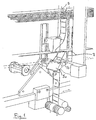
- Fig. 1
- shows the parts of a machine for production of Venetian lath blinds after insertion of a lath, which parts are important to the invention, and
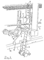
- Fig. 2
- the same parts, but after insertion of the following lath.
- The machine shown on the drawing includes a number of identical work stations, viz. a station for each ladder band with which the Venetian lath blind is to be provided depending on the dimensions of the laths.
- Each work station has carrier 1 to support the last inserted
lath 2 in a known way which is irrelevant to the invention. The carrier 1 has a slit through which aladder 3 consisting of bands or strings stretches downward from previously inserted laths 2' and/or aseparate holder 4 to a ladder supply not shown. On both sides of the slit the carrier 1 has carrier faces 5 which slope away from each other on both sides of the slit and turn on an axis 6 stretching across the lower side of the insertedlath 2. The carrier 1 can be swung between a position in which one carrier face 5 supports alath 2 and another position in which the other carrier face supports a lath. The swing is effected in a way described later so that the two carrier faces alternately support consecutive laths. The carrier 1 lifts thelath 2 so that it is gripped bypawls 7 in a magazine, and when the carrier moves down it is turned because of the special design of theguide plate 11. On account of the swing the suspended ladder is moved at the same time so that the cross bands are on one and the other side alternately of apunched hole 8 inlaths 2,2'. - A
downward arm 9 is fixed to the carrier 1 of the shown embodiment. Aroller 10 which works together with aguide plate 11 is fixed to the lower end of the arm. The guide disc is fixed to apush bar 12 which can reciprocate synchronously with the feed mechanism forlaths 2,2', not shown. Theguide plate 11 is designed in such a way that the carrier 1 is swung as described above whenever alath 2 is inserted and supported by a carrier face 5.
Claims (2)
- A machine for production of finished lath packs for Venetian lath blinds, the superjacent laths (2,2') of which have punched holes (8) at least at the ends for draw cords and ladders (3) consisting of bands or strings, every cross band of which carries a lath, and where one of two neighbouring cross bands of a ladder is placed on one side while the other is placed on the other side of a draw cord passed through the punched holes (8), which machine has a mechanism which inserts laths (2) one by one over a cross band in the suspended ladders (3) and at each of the suspended ladders a mechanism (1) which lifts the inserted lath and the ladders (3) so that the next lath is inserted over the following cross band of the ladders and devices to retain the raised lath, whereby each lifting mechanism has a carrier (1) and the machine has devices (9-12) to swing the carriers (1) on an axis (6) stretching across the lower side of the inserted lath between one end position and another end position synchronously with the movement of the feed mechanism, characterized in that each carrier (1) has a slit through which the suspended ladder (3) stretches and, on both sides of the slit, carrier faces (5a,5b) sloping away from each other for supporting an inserted lath (2), whereby one carrier face (5a) supports the lath in said one end position and the other carrier face (56) supports the lath in said other end position.
- A machine as claimed in claim 1, characterized in that a downward arm (9) and a curve roller (10) are fixed to each carrier (1) and that said devices for swinging the carriers (1) include a push bar (12) reciprocated by the feed mechanism under the inserted laths (2), to which push bar (12) guide plates (11) are fixed which work together with said curve rollers (10).
Priority Applications (1)
| Application Number | Priority Date | Filing Date | Title |
|---|---|---|---|
| AT90907182T ATE94615T1 (en) | 1989-04-25 | 1990-04-17 | DEVICE FOR JOINING BLINDS RODS. |
Applications Claiming Priority (2)
| Application Number | Priority Date | Filing Date | Title |
|---|---|---|---|
| DK1992/89 | 1989-04-25 | ||
| DK199289A DK160892C (en) | 1989-04-25 | 1989-04-25 | APPLIANCES FOR MANUFACTURING FINISHED BLACK PACKAGES FOR PERSONS |
Publications (2)
| Publication Number | Publication Date |
|---|---|
| EP0470147A1 EP0470147A1 (en) | 1992-02-12 |
| EP0470147B1 true EP0470147B1 (en) | 1993-09-15 |
Family
ID=8109309
Family Applications (1)
| Application Number | Title | Priority Date | Filing Date |
|---|---|---|---|
| EP90907182A Expired - Lifetime EP0470147B1 (en) | 1989-04-25 | 1990-04-17 | Apparatus for assembling slats of venetian blinds |
Country Status (8)
| Country | Link |
|---|---|
| US (1) | US5179771A (en) |
| EP (1) | EP0470147B1 (en) |
| AU (1) | AU632573B2 (en) |
| CA (1) | CA2053877A1 (en) |
| DE (1) | DE69003387T2 (en) |
| DK (1) | DK160892C (en) |
| ES (1) | ES2044588T3 (en) |
| WO (1) | WO1990012947A1 (en) |
Families Citing this family (2)
| Publication number | Priority date | Publication date | Assignee | Title |
|---|---|---|---|---|
| KR0145007B1 (en) * | 1992-07-31 | 1998-07-15 | 강진구 | Video library system and realization method thereof |
| DK170180B1 (en) * | 1992-12-29 | 1995-06-06 | Fabers Fab As C | Process for manufacturing blinds for blinds as well as mechanism for use in the practice of the method |
Family Cites Families (5)
| Publication number | Priority date | Publication date | Assignee | Title |
|---|---|---|---|---|
| DE2535453C2 (en) * | 1975-08-08 | 1986-12-11 | Hunter Douglas Industries B.V., Rotterdam | Device for finishing slatted blinds |
| DE2644276C2 (en) * | 1976-09-30 | 1985-01-17 | Hunter Douglas Industries B.V., Rotterdam | Machine for assembling blinds that can be drawn up |
| US4516300A (en) * | 1983-08-01 | 1985-05-14 | Hunter Douglas International N.V. | Apparatus and a method for assembling slats of a venetian blind |
| GB2197012A (en) * | 1986-10-30 | 1988-05-11 | Teh Yor Ind Company Ltd | Producing venetian blinds |
| NL8702890A (en) * | 1987-12-02 | 1989-07-03 | Hunter Douglas Ind Bv | SLAT BLIND ASSEMBLY METHOD, ASSEMBLY, AND CARRYING LADDER. |
-
1989
- 1989-04-25 DK DK199289A patent/DK160892C/en not_active IP Right Cessation
-
1990
- 1990-04-17 DE DE90907182T patent/DE69003387T2/en not_active Expired - Fee Related
- 1990-04-17 WO PCT/DK1990/000098 patent/WO1990012947A1/en not_active Ceased
- 1990-04-17 EP EP90907182A patent/EP0470147B1/en not_active Expired - Lifetime
- 1990-04-17 AU AU56311/90A patent/AU632573B2/en not_active Ceased
- 1990-04-17 CA CA002053877A patent/CA2053877A1/en not_active Abandoned
- 1990-04-17 ES ES90907182T patent/ES2044588T3/en not_active Expired - Lifetime
-
1991
- 1991-10-25 US US07/768,628 patent/US5179771A/en not_active Expired - Fee Related
Also Published As
| Publication number | Publication date |
|---|---|
| AU632573B2 (en) | 1993-01-07 |
| AU5631190A (en) | 1990-11-16 |
| EP0470147A1 (en) | 1992-02-12 |
| DK199289D0 (en) | 1989-04-25 |
| US5179771A (en) | 1993-01-19 |
| DK199289A (en) | 1990-10-26 |
| WO1990012947A1 (en) | 1990-11-01 |
| DK160892B (en) | 1991-04-29 |
| ES2044588T3 (en) | 1994-01-01 |
| CA2053877A1 (en) | 1990-10-26 |
| DE69003387D1 (en) | 1993-10-21 |
| DE69003387T2 (en) | 1994-03-31 |
| DK160892C (en) | 1991-10-21 |
Similar Documents
| Publication | Publication Date | Title |
|---|---|---|
| US4639987A (en) | Apparatus for producing simultaneously a plurality of Venetian blinds | |
| EP0317213B1 (en) | Device for transferring printed circuit board | |
| US3736631A (en) | Ladder mechanism for an assembling apparatus for the manufacture of completely or partly finished packages of slats for venetian blinds | |
| US4073044A (en) | Apparatus for assembling louvred blinds | |
| US3292232A (en) | Method and apparatus for assembling venetian blinds | |
| GB1582175A (en) | Method and apparatus for introducing a venetian blind slat or a slat-forming strip in the production of venetian blinds | |
| EP0265564A1 (en) | Apparatus to trim an assembled venetian blind to a given length | |
| EP0470147B1 (en) | Apparatus for assembling slats of venetian blinds | |
| US4606099A (en) | Method and apparatus for manufacturing an armor shutter | |
| EP0133759B1 (en) | Apparatus and a method for assembling slats of a venetian blind | |
| EP0689497B1 (en) | Punching devices | |
| CA1232750A (en) | Apparatus for assembling slatted venetian blinds | |
| US5099556A (en) | Method and apparatus for mechanically assembling a venetian blind | |
| US6443042B1 (en) | Method and apparatus for manufacturing a wood blind | |
| EP0297759B1 (en) | Venetian blind assembly method and apparatus | |
| CN220907832U (en) | Button sewing machine | |
| EP0879339A1 (en) | A new slat lifting unit for blind making machines | |
| EP0297183A1 (en) | Apparatus for mechanically assembling a venetian blind | |
| AU738962B2 (en) | Venetian blind lacing station | |
| US3471915A (en) | Apparatus for selectively feeding and assembling card components of different types | |
| GB2253228A (en) | Apparatus for mechanically assembling slats of a venetian blind | |
| CN115972302A (en) | Perforating device of LED lamp strip processing equipment | |
| FR2672624B1 (en) | CONSTRUCTION PANEL BASED ON ADHESIVE BLADE, AND ITS MANUFACTURING METHOD. | |
| PL378520A1 (en) | A venetian blind | |
| JPH08108230A (en) | Guiding device for punch tool |
Legal Events
| Date | Code | Title | Description |
|---|---|---|---|
| PUAI | Public reference made under article 153(3) epc to a published international application that has entered the european phase |
Free format text: ORIGINAL CODE: 0009012 |
|
| 17P | Request for examination filed |
Effective date: 19911008 |
|
| AK | Designated contracting states |
Kind code of ref document: A1 Designated state(s): AT DE ES GB IT NL SE |
|
| 17Q | First examination report despatched |
Effective date: 19921124 |
|
| GRAA | (expected) grant |
Free format text: ORIGINAL CODE: 0009210 |
|
| AK | Designated contracting states |
Kind code of ref document: B1 Designated state(s): AT DE ES GB IT NL SE |
|
| REF | Corresponds to: |
Ref document number: 94615 Country of ref document: AT Date of ref document: 19931015 Kind code of ref document: T |
|
| REF | Corresponds to: |
Ref document number: 69003387 Country of ref document: DE Date of ref document: 19931021 |
|
| ITF | It: translation for a ep patent filed | ||
| REG | Reference to a national code |
Ref country code: ES Ref legal event code: FG2A Ref document number: 2044588 Country of ref document: ES Kind code of ref document: T3 |
|
| PLBE | No opposition filed within time limit |
Free format text: ORIGINAL CODE: 0009261 |
|
| STAA | Information on the status of an ep patent application or granted ep patent |
Free format text: STATUS: NO OPPOSITION FILED WITHIN TIME LIMIT |
|
| 26N | No opposition filed | ||
| EAL | Se: european patent in force in sweden |
Ref document number: 90907182.1 |
|
| PGFP | Annual fee paid to national office [announced via postgrant information from national office to epo] |
Ref country code: GB Payment date: 19980409 Year of fee payment: 9 |
|
| PGFP | Annual fee paid to national office [announced via postgrant information from national office to epo] |
Ref country code: ES Payment date: 19980414 Year of fee payment: 9 |
|
| PGFP | Annual fee paid to national office [announced via postgrant information from national office to epo] |
Ref country code: AT Payment date: 19980424 Year of fee payment: 9 |
|
| PGFP | Annual fee paid to national office [announced via postgrant information from national office to epo] |
Ref country code: SE Payment date: 19980429 Year of fee payment: 9 |
|
| PGFP | Annual fee paid to national office [announced via postgrant information from national office to epo] |
Ref country code: NL Payment date: 19980430 Year of fee payment: 9 |
|
| PGFP | Annual fee paid to national office [announced via postgrant information from national office to epo] |
Ref country code: DE Payment date: 19980526 Year of fee payment: 9 |
|
| PG25 | Lapsed in a contracting state [announced via postgrant information from national office to epo] |
Ref country code: GB Free format text: LAPSE BECAUSE OF NON-PAYMENT OF DUE FEES Effective date: 19990417 Ref country code: AT Free format text: LAPSE BECAUSE OF NON-PAYMENT OF DUE FEES Effective date: 19990417 |
|
| PG25 | Lapsed in a contracting state [announced via postgrant information from national office to epo] |
Ref country code: SE Free format text: LAPSE BECAUSE OF NON-PAYMENT OF DUE FEES Effective date: 19990418 |
|
| PG25 | Lapsed in a contracting state [announced via postgrant information from national office to epo] |
Ref country code: ES Free format text: LAPSE BECAUSE OF NON-PAYMENT OF DUE FEES Effective date: 19990419 |
|
| PG25 | Lapsed in a contracting state [announced via postgrant information from national office to epo] |
Ref country code: NL Free format text: LAPSE BECAUSE OF NON-PAYMENT OF DUE FEES Effective date: 19991101 |
|
| GBPC | Gb: european patent ceased through non-payment of renewal fee |
Effective date: 19990417 |
|
| NLV4 | Nl: lapsed or anulled due to non-payment of the annual fee |
Effective date: 19991101 |
|
| EUG | Se: european patent has lapsed |
Ref document number: 90907182.1 |
|
| PG25 | Lapsed in a contracting state [announced via postgrant information from national office to epo] |
Ref country code: DE Free format text: LAPSE BECAUSE OF NON-PAYMENT OF DUE FEES Effective date: 20000201 |
|
| REG | Reference to a national code |
Ref country code: ES Ref legal event code: FD2A Effective date: 20010503 |
|
| PG25 | Lapsed in a contracting state [announced via postgrant information from national office to epo] |
Ref country code: IT Free format text: LAPSE BECAUSE OF NON-PAYMENT OF DUE FEES Effective date: 20050417 |