EP0469828A1 - Brake assembly for a control rod drive - Google Patents
Brake assembly for a control rod drive Download PDFInfo
- Publication number
- EP0469828A1 EP0469828A1 EP91306925A EP91306925A EP0469828A1 EP 0469828 A1 EP0469828 A1 EP 0469828A1 EP 91306925 A EP91306925 A EP 91306925A EP 91306925 A EP91306925 A EP 91306925A EP 0469828 A1 EP0469828 A1 EP 0469828A1
- Authority
- EP
- European Patent Office
- Prior art keywords
- brake member
- shaft
- rotor
- brake
- tooth
- Prior art date
- Legal status (The legal status is an assumption and is not a legal conclusion. Google has not performed a legal analysis and makes no representation as to the accuracy of the status listed.)
- Withdrawn
Links
Images


Classifications
-
- G—PHYSICS
- G21—NUCLEAR PHYSICS; NUCLEAR ENGINEERING
- G21C—NUCLEAR REACTORS
- G21C7/00—Control of nuclear reaction
- G21C7/06—Control of nuclear reaction by application of neutron-absorbing material, i.e. material with absorption cross-section very much in excess of reflection cross-section
- G21C7/08—Control of nuclear reaction by application of neutron-absorbing material, i.e. material with absorption cross-section very much in excess of reflection cross-section by displacement of solid control elements, e.g. control rods
- G21C7/12—Means for moving control elements to desired position
-
- Y—GENERAL TAGGING OF NEW TECHNOLOGICAL DEVELOPMENTS; GENERAL TAGGING OF CROSS-SECTIONAL TECHNOLOGIES SPANNING OVER SEVERAL SECTIONS OF THE IPC; TECHNICAL SUBJECTS COVERED BY FORMER USPC CROSS-REFERENCE ART COLLECTIONS [XRACs] AND DIGESTS
- Y02—TECHNOLOGIES OR APPLICATIONS FOR MITIGATION OR ADAPTATION AGAINST CLIMATE CHANGE
- Y02E—REDUCTION OF GREENHOUSE GAS [GHG] EMISSIONS, RELATED TO ENERGY GENERATION, TRANSMISSION OR DISTRIBUTION
- Y02E30/00—Energy generation of nuclear origin
- Y02E30/30—Nuclear fission reactors
-
- Y—GENERAL TAGGING OF NEW TECHNOLOGICAL DEVELOPMENTS; GENERAL TAGGING OF CROSS-SECTIONAL TECHNOLOGIES SPANNING OVER SEVERAL SECTIONS OF THE IPC; TECHNICAL SUBJECTS COVERED BY FORMER USPC CROSS-REFERENCE ART COLLECTIONS [XRACs] AND DIGESTS
- Y10—TECHNICAL SUBJECTS COVERED BY FORMER USPC
- Y10T—TECHNICAL SUBJECTS COVERED BY FORMER US CLASSIFICATION
- Y10T74/00—Machine element or mechanism
- Y10T74/18—Mechanical movements
- Y10T74/18568—Reciprocating or oscillating to or from alternating rotary
- Y10T74/18576—Reciprocating or oscillating to or from alternating rotary including screw and nut
- Y10T74/18696—Reciprocating or oscillating to or from alternating rotary including screw and nut including means to selectively transmit power [e.g., clutch, etc.]
Definitions
- the present invention relates generally to control rod drives used in nuclear reactors and, more specifically, to a brake assembly effective for preventing rotation of the control rod drive when engaged.
- control rods are selectively inserted and withdraw from a nuclear reactor vessel for controlling the operation thereof.
- Each of the control rods is typically positioned by a conventional control rod drive which includes a ball screw or spindle operatively engaging a ball nut for raising and lowering the ball nut as the spindle is rotated either clockwise or counterclockwise.
- a hollow piston rests upon the ball nut at one end thereof and at its other end is conventionally joined to the control rod. Displacement of the ball nut provides displacement of the piston which in turn inserts or withdraws the control rod in the reactor vessel.
- a rapid flow of high-pressure water is injected through the control rod drive past the piston for lifting the piston off the ball nut in a relatively short time for quickly inserting the control rod into the reactor vessel.
- the high-pressure water is channeled to the control rod drive through a scram line pipe attached to a high-pressure water accumulator.
- the backflow may cause a large reverse pressure on the piston which in turn provides a back force on the control rod ball nut.
- This back force can cause reverse rotation of the ball spindle with corresponding withdrawal of the control rod.
- Withdrawal of one of the control rods due to such a backflow occurrence may cause damage to adjacent fuel in the reactor vessel, requiring replacement thereof leading to undesirable down time of the reactor and economic losses.
- a conventional electromechanical brake is provided in the control rod drive for holding the ball spindle from rotating unless the brake is energized.
- the brake is sized for restraining rotation of the ball spindle against such forces due to backflow of water over the piston when the control rod drive motor is not operating.
- the motor itself is sized for providing adequate torque for resisting the forces due to the backflow of water in the event of the above-described occurrence.
- the brake is periodically tested.
- the brakes are located adjacent to the reactor vessel, which is inaccessible during operation of the reactor due to the radiation field emanating from the reactor vessel.
- the radiation field continues at reduced levels also during shutdow of the reactor, which would require inspectors to wear suitable protective clothing and limit their time in the area.
- one object of the present invention is to provide a new and improved brake assembly for preventing rotation of a shaft.
- Another object of the present invention is to provide a brake assembly effective for providing a positive rotational restraint of the shaft in one direction while allowing rotation thereof in an opposite direction.
- Another object of the present invention is to provide a relatively simple and compact brake assembly for a shaft.
- Another object of the present invention is to provide a brake assembly which is relatively easily testable.
- Another object of the present invention is to provide a brake assembly for preventing rotation of a control rod drive for a nuclear reactor and which may be actuated and tested remotely.
- a brake assembly for selectively preventing rotation of a shaft, such as a shaft used in a control rod drive for a nuclear reactor.
- the brake assembly includes a stationary base, a rotor disc fixedly connected to the shaft for rotation therewith, and a brake member disposed adjacent to the rotor disc.
- the rotor disc includes at least one rotor tooth and the brake member includes at least one braking tooth.
- Means are disclosed for selectively positioning the brake member in a deployed position for allowing the braking tooth to contact the rotor tooth for preventing rotation of the shaft in a first direction, and in a retracted position for allowing the rotor disc and shaft to rotate without restraint from the brake member.
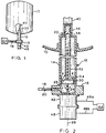
- Figure 1 is a schematic representation of a nuclear reactor vessel including a control rod drive having a brake assembly in accordance with one embodiment of the present invention.
- Figure 2 is an enlarged sectional view, partly schematic, of the control rod drive illustrated in Figure 1.
- Figure 3 is a longitudinal transverse partly sectional view of the brake assembly illustrated in Figures 1 and 2 in accordance with one embodiment of the present invention with a brake member disposed in a retracted position.
- Figure 4 is a transverse sectional view of the brake assembly illustrated in Figure 3 taken along line 4-4.
- Figure 5 is a perspective view of a portion of the rotor disc illustrated in Figure 4 taken along line 5-5.
- Figure 6 is a transverse sectional view of the brake assembly illustrated in Figure 3 taken along line 6-6.
- Figure 7 is a perspective view of a portion of the brake member illustrated in Figure 6 taken along line 7-7.
- Figure 8 is a longitudinal transverse partly sectional view of the brake assembly illustrated in Figures 1 and 2 show with the brake member disposed in a deployed position.
- FIG. 1 Illustrated in Figure 1 is an exemplary nuclear reactor vessel 10 having a plurality of fine motion control rod drives 12 (FMCRD), only one of which is shown. In one exemplary embodiment, there are 205 FMCRDs 12 extending into the vessel 10 through the bottom thereof.
- FMCRD fine motion control rod drives
- the rod drive 12 includes a tubular housing 14 extending outwardly from the vessel 10 and conventionally secured thereto.
- the housing 14 is conventionally connected to a manifold 16 which is disposed in flow communication with a scram line or conduit 18 which is conventionally selectively provided with high-pressure water 20 from a conventional high-pressure water accumulator 22 conventionally joined to the scram line 18.
- a conventional ball screw or spindle 24 Conventionally disposed inside the housing 14 is a conventional ball screw or spindle 24, which in this exemplary embodiment includes conventional right-handed threads 26.
- the control rod drive 12 includes a longitudinal centerline axis 28, with the housing 12 and spindle 24 being disposed coaxially therewith.
- a conventional ball nut 30 is positioned over the spindle 24 and is conventionally restrained from rotating therewith so that as the spindle is rotated in a clockwise direction, the ball nut is translated in a downward direction away from the vessel 10, and when the spindle is rotated in a counterclockwise direction, the ball nut 30 is translated in an upward direction toward the vessel 10.
- a conventional hollow, elongate piston 32 is disposed coaxially with the spindle 24 and includes a conical base end 34 which rests on the ball nut 30, and a tip end 36 extending through a central aperture 38 in the outer end of the housing 14 into the vessel 10. The tip end 36 is conventionally coupled to a respective control rod 40 by a bayonet coupling, for example.
- the spindle 24 extends dowwardly from the manifold 16 through a conventional electrical motor 42 which selectively rotates the spindle 24 in either the clockwise direction or counterclockwise direction.
- the motor 42 is electrically connected to a conventional control 44 by a conventional electrical line 46a for selectively controlling operation of the motor 42.
- the rod drive 12 further includes a brake assembly 48 joined to the motor 42 into which extends the spindle 24, also referred to as an input shaft 24.
- the brake assembly 48 is electrically joined to the control 44 by a conventional electrical line 46b for selectively braking and unbraking, or releasing, the input shaft 24.
- the brake assembly 48 includes an annular stationary base 50 conventionally fixedly secured to the motor 42, for example by bolts (not shown).
- the base 50 includes a central aperture 52 which receives a portion of the shaft 24 extending from the motor 42.
- an annular housing 54 of the brake assembly 48 Disposed coaxially with the shaft centerline axis 28 is an annular housing 54 of the brake assembly 48 which is conventionally fixedly secured to the base 50.
- the brake assembly 48 further includes an annular rotor disc 56 having a central aperture 58, as show in more detail in Figure 4, surrounding the shaft 24 and fixedly connected to the shaft 24 for rotation therewith by a conventional key 60.
- the rotor disc 56 has at least one and preferably a plurality of rotor teeth 62 extending circumferentially around the rotor disc 56 and extending outwardly from a first surface 64 of the rotor disc 56.
- An opposite, second surface 66 of the rotor disc 56 faces the motor 42.
- each of the rotor teeth 62 includes a locking surface 68 which extends generally perpendicularly outwardly from the first surface 64 and generally parallel to the centerline axis 28 and also in a radial direction relative to the shaft centerline axis 28 as illustrated more particularly in Figures 4 and 5.
- Each rotor tooth 62 further includes an inclined surface 70 extending from the first surface 64 to the outer end of the locking surface 68 in the circumferential direction.
- the locking surface 68 and the inclined surface 70 define a generally sawtooth profile for the rotor tooth 62.
- a nonrotating brake member 72 as shown in Figures 3, 6 and 7 is disposed adjacent to the rotor disc 56 and includes an annular base 74 having a central aperture 76 receiving the shaft 24 for rotation relative thereto.
- the brake member 72 includes a first surface 78 facing the rotor disc first surface 64, and a second, planar surface 80 facing away from the rotor disc 56.
- At least one and preferably a plurality of braking teeth 82 are formed integrally with the base 74 and extend outwardly from the first surface 78.
- Each of the braking teeth 82 has a sawtooth profile complementary to the rotor teeth 62 including a locking surface 84 extending outwardly from the first surface 78 as illustrated in more particularity in Figures 3 and 7 and generally parallel to the shaft longitudinal axis 28 and also in a radial direction relative to the shaft centerline axis 28.
- Each of the braking teeth 82 also includes an inclined surface 86 extending outwardly from the first surface 78 to the outer end of the locking surface 84 and extends in a circumferential direction at a radial position equal to the radial position of the rotor teeth 62 relative to the centerline axis 28 so that the rotor and braking teeth 62 and 82 face each other.
- the brake assembly 48 further includes means 88 for selectively positioning the brake member 72 in a deployed, locking position designated 72a, as shown in Figure 8, for allowing the braking teeth 82 to mesh with the rotor teeth 62 with the braking teeth locking surfaces 84 contacting the rotor teeth locking surfaces 68 for preventing rotation of the shaft 24 in a first, clockwise direction.
- the relative positions of the locking surfaces 68 and 84 against each other in the deployed position 72a are also show in solid and dashed lines in Figures 4 and 6.
- the positioning means 88 are also effective for positioning the brake member 72 in a retracted position designated 72b, as show in Figure 3, spaced longitudinally away from the rotor disc 56 for allowing the rotor disc 56 and the shaft 24 to rotate without restraint from the brake member 72.
- the positioning means 88 is effective for resiliently supporting the braking teeth 82 for allowing the rotor teeth inclined surfaces 70 to longitudinally displace the brake member 72 and the braking teeth inclined surfaces 86 to intermittently free the rotor teeth locking surfaces 68 from the braking teeth locking surfaces 84 for allowing the shaft 24 to rotate in a second, counterclockwise direction opposite to the first direction when the brake member 72 is in the deployed position 72a as illustrated in Figure 8.
- the positioning means 88 preferably includes a plurality of circumferentially spaced guide holes 90 extending transversely through the outer perimeter of the brake member 72, as shown in more particularity in Figures 6 and 7, which guide holes 90 are disposed parallel to the centerline axis 28.
- a plurality of complementary guide rods 92 are conventionally fixedly joined to the base 50, for example by being formed integrally therewith or being threaded therein, and extend parallel to the shaft centerline axis 28.
- the guide rods 92 are circumferentially spaced from each other with each guide rod 92 being longitudinally slidably disposed in a respective one of the guide holes 90 for allowing the brake member 72 to translate longitudinally along the guide rods 92 and parallel to the centerline axis 28.
- the guide rods 92 are also effective for preventing rotational movement of the brake member 72 relative to the shaft centerline axis 28 while allowing longitudinal movement relative thereto.
- the positioning means 88 also includes a conventional electromagnet 94 as illustrated in Figures 3 and 8 which is spaced from the brake member second surface 80 and fixedly joined to the plurality of guide rods 92 by nuts 96 for example.
- the electromagnet 94 includes a conventional wire coil 98 electrically connected to the control 44 by the electrical line 46b.
- the coil 98 is conventionally secured to an annular support plate 100 having a plurality of circumferentially spaced support holes 102 through which are received respective ends of the guide rods 92 for fixedly attaching the support plate 100 thereto using the nuts 96.
- a plurality of compression springs 104 as illustrated in Figures 3 and 8 are disposed around respective ones of the guide rods 92 and preferably between the electromagnet support plate 100 and the brake member second surface 80 for providing a deploying force on and preferably against the brake member 72 for positioning the brake member 72 in the deployed position 72a against the rotor disc 56 as illustrated in Figure 8 when the electromagnet 94 is de-energized.
- the compression springs 104 are disposed between the electromagnet support plate 100 and the brake member second surface 80 and are predeterminedly initially compressed for providing the deploying force against the brake member 72.
- the electromagnet 94 is conventionally sized for being effective for magnetically attracting the brake member 72, which is formed from a conventional magnetic material, for overcoming the deploying force and further compressing the springs 104 for positioning the brake member 72 in the retracted position 72b as illustrated in Figure 3 when the electromagnet 94 is energized.
- the springs 104 exert the deploying force against the brake member 72 which positions the brake member 72 in the deployed position 72a.
- the brake assembly 48 in accordance with the preferred embodiment, provides complementary sawtooth profiled rotor and brake teeth 62 and 82 which are effective for locking the shaft 24 and preventing rotation in preferably one direction, e.g. clockwise direction only when the electromagnet 94 is de-energized.
- This positive locking of the shaft 24 prevents rotation of the shaft 24 in a clockwise direction for preventing inadvertent withdrawal of the control rod 40 under the back flow occurrence, for example.
- the brake member 72 is retracted from the rotor disc 56 allowing the shaft 24 to rotate and then the motor 42 may be conventionally operated for predeterminedly either inserting or withdrawing the control rod 40.
- An additional advantage of the preferred positioning means 88 and teeth 62 and 82 allows for rotation of the shaft 24 in the counterclockwise direction even when the electromagnet 94 is de-energized and the brake member 72 is disposed in the deployed position 72a as illustrated in Figure 8.
- the motor 42 may be predeterminedly actuated for further inserting the control rod 40 into the vessel 10 even while the brake member 72 is in the deployed position 72b.
- the shaft 24 will be turned by the motor 42 in the counterclockwise direction causing the rotor teeth inclined surfaces 70 to longitudinally displace downward the braking teeth inclined surfaces 86, and thereby the brake member 72, by a camming action in a ratcheting fashion for intermittently freeing the rotor teeth locking surfaces 68 from the braking teeth locking surfaces 84 for allowing counterclockwise rotation of the shaft 24.
- the position of the brake member 72, initially in the deployed position 72a, due to this ratcheting action is designated 72c and is shown in dashed line in Figure 8.
- the brake member 72 is initially in the deployed position 72a and is then urged downwardly away from the rotor disc 56 by the rotor teeth 62 until the ratcheting deployed position 72c is reached at the longitudinal extent of travel of the brake member 72 due to the height of the locking surface 68.
- the rotor teeth 62 are displaced one rotor tooth position relative to the braking teeth 82 with a respective rotor tooth inclined surface 70 then facing the next succeeding braking tooth inclined surface 86 with a corresponding upward movement of the brake member 72 toward the rotor disc 56 by the springs 104.
- the rotor teeth inclined surfaces 70 will then again urge respective braking teeth inclined surfaces 86 downward until the rotor teeth 62 again ratchet one tooth relative to the braking teeth 82. Accordingly, the rotor teeth locking surfaces 68 are intermittently freed from the braking teeth locking surfaces 84 as the shaft 24 rotates counterclockwise with the brake member 72 disposed in the deployed position 72a.
- the brake assembly 48 as described above thus provides a positive lock of the shaft 24 to prevent unintentional ejection travel of the control rod 40 from the vessel 10 while allowing for both insertion of the control rod 40 while the brake member 72 is disposed in the deployed position and allowing for relatively simple testing of the brake assembly 48.
- the brake assembly 48 may be simply tested by de-energizing the electromagnet 94 for positioning the brake member 72 in the deployed position 72a and then energizing the motor 42 to allow the rotor teeth locking surfaces 68 to abut against, and be circumferentially restrained by the braking teeth locking surfaces 84 for preventing further rotation of the shaft 24. Since the motor 42 will be unable to rotate the shaft 24 relative to the brake member 72 in a clockwise direction, the motor 42 will stall, which may be conventionally observed by the control 44 for indicating the effective operation of the brake assembly 48. If the brake assembly 48 is unable to prevent the clockwise rotation of the shaft 24 during testing, the control 44 can provide a suitable indication thereof, which may then result in manual inspection of the brake assembly 48 for correcting any problem that might exist.
- the above described brake assembly 48 in accordance with the present invention provides a positive, unidirectional restraint which locks the shaft 24 from unintentional rotation in a predetermined direction which provides an improvement over a conventional friction-type brake which may allow for slippage.
- the brake assembly 48 may be tested remotely as described above so that access to the environment adjacent to the nuclear reactor vessel 10 is not required. Yet further, the brake assembly 48 may be tested relatively quickly during normal operation of the reactor vessel 10 without requiring down time of the reactor solely for testing purposes.
- the rotor and braking teeth 62 and 82 are show in the preferred embodiment as extending from the respective first surfaces 64 and 78 of the rotor disc 56 and the brake member 72, respectively, other configurations of the teeth 62, 82 may be used in accordance with the present invention.
- the rotor teeth 62 in an alternate embodiment may extend radially outwardly around the outer perimeter of the rotor disc 56 with the braking teeth 82 extending radially inwardly from an inner annulus of a brake member surrounding the rotor disc 56.
- Suitable positioning means 88 could be used in such an embodiment for positioning the braking teeth in deployed and retracted positions for locking and unlocking the shaft 24 for obtaining unidirectional restraint.
Landscapes
- Physics & Mathematics (AREA)
- Engineering & Computer Science (AREA)
- Chemical & Material Sciences (AREA)
- Chemical Kinetics & Catalysis (AREA)
- Plasma & Fusion (AREA)
- General Engineering & Computer Science (AREA)
- High Energy & Nuclear Physics (AREA)
- Braking Arrangements (AREA)
Abstract
A brake assembly is disclosed for selectively preventing rotation of a shaft, such as a shaft used in a control rod drive for a nuclear reactor. The brake assembly includes a stationary base, a rotor disc fixedly connected to the shaft for rotation therewith, and a brake member disposed adjacent to the rotor disc. The rotor disc includes at least one rotor tooth and the brake member includes at least one braking tooth. Means are disclosed for selectively positioning the brake member in a deployed position for allowing the braking tooth to contact the rotor tooth for preventing rotation of the shaft in a first direction while permitting rotation in the opposite direction, and in a retracted position for allowing the rotor disc and shaft to rotate in either direction without restraint from the brake member.
Description
- The present invention relates generally to control rod drives used in nuclear reactors and, more specifically, to a brake assembly effective for preventing rotation of the control rod drive when engaged.
- In one type of nuclear reactor, control rods are selectively inserted and withdraw from a nuclear reactor vessel for controlling the operation thereof. Each of the control rods is typically positioned by a conventional control rod drive which includes a ball screw or spindle operatively engaging a ball nut for raising and lowering the ball nut as the spindle is rotated either clockwise or counterclockwise. A hollow piston rests upon the ball nut at one end thereof and at its other end is conventionally joined to the control rod. Displacement of the ball nut provides displacement of the piston which in turn inserts or withdraws the control rod in the reactor vessel.
- In order to achieve faster insertion of the control rod than could be obtained by normal rotation of the ball spindle, which is conventionally referred to as a scram operation, a rapid flow of high-pressure water is injected through the control rod drive past the piston for lifting the piston off the ball nut in a relatively short time for quickly inserting the control rod into the reactor vessel. The high-pressure water is channeled to the control rod drive through a scram line pipe attached to a high-pressure water accumulator.
- In one type of occurrence which allows for rapid backflow of the water past the piston, due to, for example, a break in the scram line, the backflow may cause a large reverse pressure on the piston which in turn provides a back force on the control rod ball nut. This back force can cause reverse rotation of the ball spindle with corresponding withdrawal of the control rod. Withdrawal of one of the control rods due to such a backflow occurrence may cause damage to adjacent fuel in the reactor vessel, requiring replacement thereof leading to undesirable down time of the reactor and economic losses.
- In order to prevent the above occurrence, a conventional electromechanical brake is provided in the control rod drive for holding the ball spindle from rotating unless the brake is energized. The brake is sized for restraining rotation of the ball spindle against such forces due to backflow of water over the piston when the control rod drive motor is not operating. And, when the control rod drive motor is operating, the motor itself is sized for providing adequate torque for resisting the forces due to the backflow of water in the event of the above-described occurrence.
- To ensure operability of the brake, the brake is periodically tested. However, the brakes are located adjacent to the reactor vessel, which is inaccessible during operation of the reactor due to the radiation field emanating from the reactor vessel. The radiation field continues at reduced levels also during shutdow of the reactor, which would require inspectors to wear suitable protective clothing and limit their time in the area. In one nuclear reactor embodiment, there are about 205 control rod drives, including a respective number of brakes, which would necessarily require a substantial amount of time for testing all of the brakes. Testing of the brakes during reactor shutdown would, therefore, be relatively costly to accomplish, which is additionally economically undesirable since the reactor is not operating for producing power.
- Since conventional electromechanical brakes typically utilize braking pads for restraining rotation of a rotor disc, they are subject to slippage. Slippage can result in undesirable partial withdrawal of the control rod during backflow occurrence, and also requires additional means for effectively testing the torque-resisting capability of the brake.
- Accordingly, one object of the present invention is to provide a new and improved brake assembly for preventing rotation of a shaft.
- Another object of the present invention is to provide a brake assembly effective for providing a positive rotational restraint of the shaft in one direction while allowing rotation thereof in an opposite direction.
- Another object of the present invention is to provide a relatively simple and compact brake assembly for a shaft.
- Another object of the present invention is to provide a brake assembly which is relatively easily testable.
- Another object of the present invention is to provide a brake assembly for preventing rotation of a control rod drive for a nuclear reactor and which may be actuated and tested remotely.
- A brake assembly is disclosed for selectively preventing rotation of a shaft, such as a shaft used in a control rod drive for a nuclear reactor. The brake assembly includes a stationary base, a rotor disc fixedly connected to the shaft for rotation therewith, and a brake member disposed adjacent to the rotor disc. The rotor disc includes at least one rotor tooth and the brake member includes at least one braking tooth. Means are disclosed for selectively positioning the brake member in a deployed position for allowing the braking tooth to contact the rotor tooth for preventing rotation of the shaft in a first direction, and in a retracted position for allowing the rotor disc and shaft to rotate without restraint from the brake member.
- The novel features believed characteristic of the invention are set forth and differentiated in the claims. The invention, in accordance with a preferred and exemplary embodiment, together with further objects and advantages thereof, is more particularly described in the following detailed description taken in conjunction with the accompanying drawing in which:
- Figure 1 is a schematic representation of a nuclear reactor vessel including a control rod drive having a brake assembly in accordance with one embodiment of the present invention.
- Figure 2 is an enlarged sectional view, partly schematic, of the control rod drive illustrated in Figure 1.
- Figure 3 is a longitudinal transverse partly sectional view of the brake assembly illustrated in Figures 1 and 2 in accordance with one embodiment of the present invention with a brake member disposed in a retracted position.
- Figure 4 is a transverse sectional view of the brake assembly illustrated in Figure 3 taken along line 4-4.
- Figure 5 is a perspective view of a portion of the rotor disc illustrated in Figure 4 taken along line 5-5.
- Figure 6 is a transverse sectional view of the brake assembly illustrated in Figure 3 taken along line 6-6.
- Figure 7 is a perspective view of a portion of the brake member illustrated in Figure 6 taken along line 7-7.
- Figure 8 is a longitudinal transverse partly sectional view of the brake assembly illustrated in Figures 1 and 2 show with the brake member disposed in a deployed position.
- Illustrated in Figure 1 is an exemplary
nuclear reactor vessel 10 having a plurality of fine motion control rod drives 12 (FMCRD), only one of which is shown. In one exemplary embodiment, there are 205FMCRDs 12 extending into thevessel 10 through the bottom thereof. Referring also to Figure 2, an enlarged, sectional view of one of thecontrol rod drives 12 is illustrated. Therod drive 12 includes atubular housing 14 extending outwardly from thevessel 10 and conventionally secured thereto. Thehousing 14 is conventionally connected to amanifold 16 which is disposed in flow communication with a scram line orconduit 18 which is conventionally selectively provided with high-pressure water 20 from a conventional high-pressure water accumulator 22 conventionally joined to thescram line 18. - Conventionally disposed inside the
housing 14 is a conventional ball screw orspindle 24, which in this exemplary embodiment includes conventional right-handed threads 26. Thecontrol rod drive 12 includes alongitudinal centerline axis 28, with thehousing 12 andspindle 24 being disposed coaxially therewith. - A
conventional ball nut 30 is positioned over thespindle 24 and is conventionally restrained from rotating therewith so that as the spindle is rotated in a clockwise direction, the ball nut is translated in a downward direction away from thevessel 10, and when the spindle is rotated in a counterclockwise direction, theball nut 30 is translated in an upward direction toward thevessel 10. A conventional hollow,elongate piston 32 is disposed coaxially with thespindle 24 and includes aconical base end 34 which rests on theball nut 30, and atip end 36 extending through acentral aperture 38 in the outer end of thehousing 14 into thevessel 10. Thetip end 36 is conventionally coupled to arespective control rod 40 by a bayonet coupling, for example. - The
spindle 24 extends dowwardly from themanifold 16 through a conventionalelectrical motor 42 which selectively rotates thespindle 24 in either the clockwise direction or counterclockwise direction. Themotor 42 is electrically connected to aconventional control 44 by a conventional electrical line 46a for selectively controlling operation of themotor 42. - In accordance with the preferred embodiment of the present invention, the
rod drive 12 further includes abrake assembly 48 joined to themotor 42 into which extends thespindle 24, also referred to as aninput shaft 24. Thebrake assembly 48 is electrically joined to thecontrol 44 by a conventionalelectrical line 46b for selectively braking and unbraking, or releasing, theinput shaft 24. - As illustrated in more particularity in Figure 3, the
brake assembly 48 includes an annularstationary base 50 conventionally fixedly secured to themotor 42, for example by bolts (not shown). Thebase 50 includes acentral aperture 52 which receives a portion of theshaft 24 extending from themotor 42. Disposed coaxially with theshaft centerline axis 28 is anannular housing 54 of thebrake assembly 48 which is conventionally fixedly secured to thebase 50. - The
brake assembly 48 further includes anannular rotor disc 56 having acentral aperture 58, as show in more detail in Figure 4, surrounding theshaft 24 and fixedly connected to theshaft 24 for rotation therewith by aconventional key 60. Therotor disc 56 has at least one and preferably a plurality ofrotor teeth 62 extending circumferentially around therotor disc 56 and extending outwardly from afirst surface 64 of therotor disc 56. An opposite,second surface 66 of therotor disc 56 faces themotor 42. - As illustrated in Figures 3-5, each of the
rotor teeth 62 includes a lockingsurface 68 which extends generally perpendicularly outwardly from thefirst surface 64 and generally parallel to thecenterline axis 28 and also in a radial direction relative to theshaft centerline axis 28 as illustrated more particularly in Figures 4 and 5. Eachrotor tooth 62 further includes aninclined surface 70 extending from thefirst surface 64 to the outer end of the lockingsurface 68 in the circumferential direction. The lockingsurface 68 and theinclined surface 70 define a generally sawtooth profile for therotor tooth 62. - A
nonrotating brake member 72 as shown in Figures 3, 6 and 7 is disposed adjacent to therotor disc 56 and includes anannular base 74 having acentral aperture 76 receiving theshaft 24 for rotation relative thereto. Thebrake member 72 includes afirst surface 78 facing the rotor discfirst surface 64, and a second,planar surface 80 facing away from therotor disc 56. At least one and preferably a plurality ofbraking teeth 82 are formed integrally with thebase 74 and extend outwardly from thefirst surface 78. Each of the brakingteeth 82 has a sawtooth profile complementary to therotor teeth 62 including a lockingsurface 84 extending outwardly from thefirst surface 78 as illustrated in more particularity in Figures 3 and 7 and generally parallel to the shaftlongitudinal axis 28 and also in a radial direction relative to theshaft centerline axis 28. Each of the brakingteeth 82 also includes aninclined surface 86 extending outwardly from thefirst surface 78 to the outer end of the lockingsurface 84 and extends in a circumferential direction at a radial position equal to the radial position of therotor teeth 62 relative to thecenterline axis 28 so that the rotor andbraking teeth - Referring to Figures 3 and 8, the
brake assembly 48 further includesmeans 88 for selectively positioning thebrake member 72 in a deployed, locking position designated 72a, as shown in Figure 8, for allowing the brakingteeth 82 to mesh with therotor teeth 62 with the brakingteeth locking surfaces 84 contacting the rotorteeth locking surfaces 68 for preventing rotation of theshaft 24 in a first, clockwise direction. The relative positions of the locking surfaces 68 and 84 against each other in the deployedposition 72a are also show in solid and dashed lines in Figures 4 and 6. The positioning means 88 are also effective for positioning thebrake member 72 in a retracted position designated 72b, as show in Figure 3, spaced longitudinally away from therotor disc 56 for allowing therotor disc 56 and theshaft 24 to rotate without restraint from thebrake member 72. - In the preferred embodiment, the positioning means 88 is effective for resiliently supporting the braking
teeth 82 for allowing the rotor teeth inclinedsurfaces 70 to longitudinally displace thebrake member 72 and the braking teeth inclinedsurfaces 86 to intermittently free the rotorteeth locking surfaces 68 from the brakingteeth locking surfaces 84 for allowing theshaft 24 to rotate in a second, counterclockwise direction opposite to the first direction when thebrake member 72 is in the deployedposition 72a as illustrated in Figure 8. - More specifically, the positioning means 88 preferably includes a plurality of circumferentially spaced guide holes 90 extending transversely through the outer perimeter of the
brake member 72, as shown in more particularity in Figures 6 and 7, which guide holes 90 are disposed parallel to thecenterline axis 28. A plurality ofcomplementary guide rods 92 are conventionally fixedly joined to thebase 50, for example by being formed integrally therewith or being threaded therein, and extend parallel to theshaft centerline axis 28. Theguide rods 92 are circumferentially spaced from each other with eachguide rod 92 being longitudinally slidably disposed in a respective one of the guide holes 90 for allowing thebrake member 72 to translate longitudinally along theguide rods 92 and parallel to thecenterline axis 28. Theguide rods 92 are also effective for preventing rotational movement of thebrake member 72 relative to theshaft centerline axis 28 while allowing longitudinal movement relative thereto. - The positioning means 88 also includes a
conventional electromagnet 94 as illustrated in Figures 3 and 8 which is spaced from the brake membersecond surface 80 and fixedly joined to the plurality ofguide rods 92 bynuts 96 for example. Theelectromagnet 94 includes aconventional wire coil 98 electrically connected to thecontrol 44 by theelectrical line 46b. Thecoil 98 is conventionally secured to anannular support plate 100 having a plurality of circumferentially spaced support holes 102 through which are received respective ends of theguide rods 92 for fixedly attaching thesupport plate 100 thereto using the nuts 96. - A plurality of compression springs 104 as illustrated in Figures 3 and 8 are disposed around respective ones of the
guide rods 92 and preferably between theelectromagnet support plate 100 and the brake membersecond surface 80 for providing a deploying force on and preferably against thebrake member 72 for positioning thebrake member 72 in the deployedposition 72a against therotor disc 56 as illustrated in Figure 8 when theelectromagnet 94 is de-energized. - More specifically, the compression springs 104 are disposed between the
electromagnet support plate 100 and the brake membersecond surface 80 and are predeterminedly initially compressed for providing the deploying force against thebrake member 72. Theelectromagnet 94 is conventionally sized for being effective for magnetically attracting thebrake member 72, which is formed from a conventional magnetic material, for overcoming the deploying force and further compressing thesprings 104 for positioning thebrake member 72 in the retractedposition 72b as illustrated in Figure 3 when theelectromagnet 94 is energized. When theelectromagnet 94 is de-energized, thesprings 104 exert the deploying force against thebrake member 72 which positions thebrake member 72 in the deployedposition 72a. - Accordingly, the
brake assembly 48 in accordance with the preferred embodiment, provides complementary sawtooth profiled rotor andbrake teeth shaft 24 and preventing rotation in preferably one direction, e.g. clockwise direction only when theelectromagnet 94 is de-energized. This positive locking of theshaft 24 prevents rotation of theshaft 24 in a clockwise direction for preventing inadvertent withdrawal of thecontrol rod 40 under the back flow occurrence, for example. When theelectromagnet 94 is energized, thebrake member 72 is retracted from therotor disc 56 allowing theshaft 24 to rotate and then themotor 42 may be conventionally operated for predeterminedly either inserting or withdrawing thecontrol rod 40. - An additional advantage of the preferred positioning means 88 and
teeth shaft 24 in the counterclockwise direction even when theelectromagnet 94 is de-energized and thebrake member 72 is disposed in the deployedposition 72a as illustrated in Figure 8. In this mode of operation, themotor 42 may be predeterminedly actuated for further inserting thecontrol rod 40 into thevessel 10 even while thebrake member 72 is in the deployedposition 72b. As illustrated in Figure 8, theshaft 24 will be turned by themotor 42 in the counterclockwise direction causing the rotor teeth inclinedsurfaces 70 to longitudinally displace downward the braking teeth inclinedsurfaces 86, and thereby thebrake member 72, by a camming action in a ratcheting fashion for intermittently freeing the rotorteeth locking surfaces 68 from the brakingteeth locking surfaces 84 for allowing counterclockwise rotation of theshaft 24. - The position of the
brake member 72, initially in the deployedposition 72a, due to this ratcheting action is designated 72c and is shown in dashed line in Figure 8. In this mode of operation, thebrake member 72 is initially in the deployedposition 72a and is then urged downwardly away from therotor disc 56 by therotor teeth 62 until the ratcheting deployedposition 72c is reached at the longitudinal extent of travel of thebrake member 72 due to the height of the lockingsurface 68. At this time, therotor teeth 62 are displaced one rotor tooth position relative to the brakingteeth 82 with a respective rotor tooth inclinedsurface 70 then facing the next succeeding braking tooth inclinedsurface 86 with a corresponding upward movement of thebrake member 72 toward therotor disc 56 by thesprings 104. If theshaft 24 continues to rotate in the counterclockwise direction, the rotor teeth inclinedsurfaces 70 will then again urge respective braking teeth inclinedsurfaces 86 downward until therotor teeth 62 again ratchet one tooth relative to the brakingteeth 82. Accordingly, the rotorteeth locking surfaces 68 are intermittently freed from the brakingteeth locking surfaces 84 as theshaft 24 rotates counterclockwise with thebrake member 72 disposed in the deployedposition 72a. - The
brake assembly 48 as described above thus provides a positive lock of theshaft 24 to prevent unintentional ejection travel of thecontrol rod 40 from thevessel 10 while allowing for both insertion of thecontrol rod 40 while thebrake member 72 is disposed in the deployed position and allowing for relatively simple testing of thebrake assembly 48. - More specifically, the
brake assembly 48 may be simply tested by de-energizing theelectromagnet 94 for positioning thebrake member 72 in the deployedposition 72a and then energizing themotor 42 to allow the rotorteeth locking surfaces 68 to abut against, and be circumferentially restrained by the brakingteeth locking surfaces 84 for preventing further rotation of theshaft 24. Since themotor 42 will be unable to rotate theshaft 24 relative to thebrake member 72 in a clockwise direction, themotor 42 will stall, which may be conventionally observed by thecontrol 44 for indicating the effective operation of thebrake assembly 48. If thebrake assembly 48 is unable to prevent the clockwise rotation of theshaft 24 during testing, thecontrol 44 can provide a suitable indication thereof, which may then result in manual inspection of thebrake assembly 48 for correcting any problem that might exist. - Accordingly, the above described
brake assembly 48 in accordance with the present invention provides a positive, unidirectional restraint which locks theshaft 24 from unintentional rotation in a predetermined direction which provides an improvement over a conventional friction-type brake which may allow for slippage. - Furthermore, the
brake assembly 48 may be tested remotely as described above so that access to the environment adjacent to thenuclear reactor vessel 10 is not required. Yet further, thebrake assembly 48 may be tested relatively quickly during normal operation of thereactor vessel 10 without requiring down time of the reactor solely for testing purposes. - While there has been described herein what is considered to be a preferred embodiment of the present invention, other modifications of the invention shall be apparent to those skilled in the art from the teachings herein, and it is, therefore, desired to be secured in the appended claims all such modifications as fall within the true spirit and scope of the invention.
- More specifically, and for example, although the rotor and
braking teeth first surfaces rotor disc 56 and thebrake member 72, respectively, other configurations of theteeth rotor teeth 62 in an alternate embodiment may extend radially outwardly around the outer perimeter of therotor disc 56 with the brakingteeth 82 extending radially inwardly from an inner annulus of a brake member surrounding therotor disc 56. Suitable positioning means 88 could be used in such an embodiment for positioning the braking teeth in deployed and retracted positions for locking and unlocking theshaft 24 for obtaining unidirectional restraint.
Claims (6)
- A brake assembly for selectively braking rotation of a shaft having a longitudinal centerline axis comprising:
a stationary base having a central aperture receiving said shaft;
a rotor disc fixedly connected to said shaft for rotation therewith and having at least one rotor tooth extending therefrom, said rotor tooth having a locking surface and an inclined surface extending therefrom;
a brake member disposed adjacent to said rotor disc and having at least one braking tooth having a locking surface and an inclined surface extending therefrom, said rotor tooth and said braking tooth being complementary to each other; and
means for selectively positioning said brake member in a deployed position abutting said rotor disc for allowing said braking tooth locking surface to contact said rotor tooth locking surface for preventing rotation of said shaft in a first direction, and in a retracted position spaced away from said rotor disc for allowing said rotor disc and said shaft to rotate without restraint from said brake member. - A brake assembly according to claim 1 wherein said positioning means is effective for resiliently supporting said braking tooth for allowing said rotor tooth inclined surface to displace said braking tooth inclined surface to intermittently free said rotor tooth locking surface from said braking tooth locking surface for allowing said shaft to rotate in a second direction opposite to said first direction when said brake member is in said deployed position.
- A brake assembly according to claim 2 wherein said brake member further comprises an annular base having a central aperture receiving said shaft, a first surface facing said rotor disc, and a second surface facing away from said rotor disc, and said braking tooth being disposed on said base first surface with said locking surface extending outwardly therefrom and in a radial direction relative to said shaft centerline axis, and with said inclined surface extending in a circumferential direction.
- A brake assembly according to claim 3 wherein said positioning means comprises:
a plurality of circumferentially spaced guide holes in said brake member;
a plurality of guide rods fixedly joined to said base and extending parallel to said shaft centerline axis, each guide rod being slidably disposed in a respective one of said guide holes;
an electromagnet spaced from said braking member second surface and fixedly joined to said plurality of guide rods;
a plurality of springs disposed around said guide rods for providing a deploying force on said brake member for positioning said brake member in said deployed position against said rotor disc; and
wherein said guide rods are effective for preventing rotational movement of said brake member relative to said shaft centerline axis and for allowing longitudinal movement relative thereto. - A brake assembly according to claim 4 wherein:
said springs are compression springs disposed between said electromagnet and said brake member second surface being initially compressed for providing said deploying force against said brake member;
said electromagnet is effective for magnetically attracting said brake member for overcoming said deploying force and positioning said brake member in said retracted position when energized, and when de-energized allowing said brake member to be positioned in said deployed position by said compression springs. - A brake assembly according to claim 5 further comprising a plurality of said rotor teeth extending circumferentially around said rotor disc and a respective plurality of said braking teeth extending circumferentially around said brake member.
Applications Claiming Priority (2)
| Application Number | Priority Date | Filing Date | Title |
|---|---|---|---|
| US07/559,743 US5131510A (en) | 1990-07-30 | 1990-07-30 | Brake assembly for a control rod drive |
| US559743 | 1990-07-30 |
Publications (1)
| Publication Number | Publication Date |
|---|---|
| EP0469828A1 true EP0469828A1 (en) | 1992-02-05 |
Family
ID=24234833
Family Applications (1)
| Application Number | Title | Priority Date | Filing Date |
|---|---|---|---|
| EP91306925A Withdrawn EP0469828A1 (en) | 1990-07-30 | 1991-07-29 | Brake assembly for a control rod drive |
Country Status (3)
| Country | Link |
|---|---|
| US (1) | US5131510A (en) |
| EP (1) | EP0469828A1 (en) |
| JP (1) | JPH04232894A (en) |
Families Citing this family (8)
| Publication number | Priority date | Publication date | Assignee | Title |
|---|---|---|---|---|
| DE102004047500A1 (en) * | 2004-09-30 | 2006-04-13 | Bosch Rexroth Aktiengesellschaft | holder |
| DE102006016611A1 (en) * | 2006-04-06 | 2007-10-18 | Ortlinghaus Gmbh Gams | safety brake |
| KR100838025B1 (en) * | 2007-01-19 | 2008-06-12 | 주식회사 경동나비엔 | Flow control valve |
| US8485318B2 (en) * | 2009-05-15 | 2013-07-16 | Paul J. Doran | Elevator rope braking system |
| DE102010053226A1 (en) * | 2010-12-03 | 2012-06-06 | Stabilus Gmbh | driving means |
| US9157528B2 (en) * | 2012-10-15 | 2015-10-13 | GM Global Technology Operations LLC | Brake mechanism for a hybrid transmission |
| CN108869581B (en) * | 2018-07-25 | 2024-03-22 | 科益展智能装备有限公司 | Bolt structure and design method thereof |
| EP4158760A1 (en) * | 2020-06-02 | 2023-04-05 | Linak A/S | Locking against rotation of electric motor of a linear actuator |
Citations (4)
| Publication number | Priority date | Publication date | Assignee | Title |
|---|---|---|---|---|
| DE1223070B (en) * | 1962-05-23 | 1966-08-18 | Licentia Gmbh | Control rod drive for nuclear reactors |
| EP0093055A1 (en) * | 1982-04-26 | 1983-11-02 | Commissariat à l'Energie Atomique | Releasable anti-ejection device for control rods in a nuclear reactor |
| EP0161976A1 (en) * | 1984-04-27 | 1985-11-21 | Commissariat A L'energie Atomique | Coupling device between a motor element and a receptor element |
| EP0305719A2 (en) * | 1987-08-31 | 1989-03-08 | General Electric Company | Centrifugal brake for control rod drive |
Family Cites Families (19)
| Publication number | Priority date | Publication date | Assignee | Title |
|---|---|---|---|---|
| US624239A (en) * | 1899-05-02 | Car-brake apparatus | ||
| US1373077A (en) * | 1917-01-29 | 1921-03-29 | Westinghouse Electric & Mfg Co | Control apparatus |
| US1827720A (en) * | 1924-06-02 | 1931-10-13 | Frank C Lamb | Motor vehicle brake |
| US1810998A (en) * | 1930-04-28 | 1931-06-23 | Bjork Olof | Backstop for motor vehicles |
| US2080544A (en) * | 1934-10-11 | 1937-05-18 | United Shoe Machinery Corp | Starting and stopping mechanism |
| US2949172A (en) * | 1958-12-16 | 1960-08-16 | Us Electrical Motors Inc | Positive lock electromagnetic brake structure |
| US3258985A (en) * | 1964-03-23 | 1966-07-05 | Jordan Controls Inc | Control apparatus for valve actuator |
| US3410381A (en) * | 1967-05-12 | 1968-11-12 | Gen Electric | Clutch mechanism control means |
| CH513493A (en) * | 1970-03-25 | 1971-09-30 | Bbc Brown Boveri & Cie | Device for monitoring the operation of a drive device of a control rod arranged in a gas-cooled nuclear reactor and serving as a regulating and emergency shutdown rod |
| DE2308131B2 (en) * | 1973-02-19 | 1979-02-08 | Fried. Krupp Gmbh, 4300 Essen | Gripping device of a lifting device, in particular in a nuclear reactor, for setting down and picking up fuel assemblies and rods |
| US4015696A (en) * | 1975-10-20 | 1977-04-05 | Lichti Robert D | Centrifugal braking device |
| US4119310A (en) * | 1976-03-26 | 1978-10-10 | Patterson-Williams Manufacturing Company | Playground turntable |
| US4238288A (en) * | 1978-05-24 | 1980-12-09 | Anikin Alexandr A | Drive of nuclear reactor S control element |
| FR2468976A1 (en) * | 1979-10-31 | 1981-05-08 | Framatome Sa | DIFFERENTIAL MOTION CHAIN MECHANISM FOR CONTROLLING A NUCLEAR REACTOR |
| US4423002A (en) * | 1979-12-19 | 1983-12-27 | Framatome | Apparatus for controlling a nuclear reactor by vertical displacement of a unit absorbing neutrons |
| IT1142782B (en) * | 1981-07-21 | 1986-10-15 | Selenia Ind Elettroniche | HYDRAULIC JACK WITH MECHANICAL SAFETY LOCK |
| US4518559A (en) * | 1982-07-08 | 1985-05-21 | General Electric Company | Control of nuclear reactors |
| JPS6263086A (en) * | 1985-09-10 | 1987-03-19 | フアナツク株式会社 | Brake structure in industrial robot |
| DE3836255A1 (en) * | 1988-10-25 | 1990-04-26 | Opel Adam Ag | ELECTRIC MOTOR ACTUATOR |
-
1990
- 1990-07-30 US US07/559,743 patent/US5131510A/en not_active Expired - Fee Related
-
1991
- 1991-07-15 JP JP3198205A patent/JPH04232894A/en active Pending
- 1991-07-29 EP EP91306925A patent/EP0469828A1/en not_active Withdrawn
Patent Citations (4)
| Publication number | Priority date | Publication date | Assignee | Title |
|---|---|---|---|---|
| DE1223070B (en) * | 1962-05-23 | 1966-08-18 | Licentia Gmbh | Control rod drive for nuclear reactors |
| EP0093055A1 (en) * | 1982-04-26 | 1983-11-02 | Commissariat à l'Energie Atomique | Releasable anti-ejection device for control rods in a nuclear reactor |
| EP0161976A1 (en) * | 1984-04-27 | 1985-11-21 | Commissariat A L'energie Atomique | Coupling device between a motor element and a receptor element |
| EP0305719A2 (en) * | 1987-08-31 | 1989-03-08 | General Electric Company | Centrifugal brake for control rod drive |
Also Published As
| Publication number | Publication date |
|---|---|
| JPH04232894A (en) | 1992-08-21 |
| US5131510A (en) | 1992-07-21 |
Similar Documents
| Publication | Publication Date | Title |
|---|---|---|
| US5102613A (en) | Radial brake assembly for a control rod drive | |
| US20220215973A1 (en) | Lower end fitting locknut for nuclear fuel assembly | |
| JP3443587B2 (en) | Control rod drive device and method of assembling the same | |
| US5131510A (en) | Brake assembly for a control rod drive | |
| US4639998A (en) | Locking tube removal and replacement tool and method in a reconstitutable fuel assembly | |
| US4649989A (en) | Device for testing and/or repairing steam generator tubes | |
| US4928291A (en) | Control cluster provided with removable control elements for a nuclear fuel reactor | |
| EP0499406B1 (en) | Control rod drive | |
| CA1111970A (en) | Tubular closure mechanism | |
| KR940004832B1 (en) | Top nozzle removal and replacement fixture and method in a reconstitutable fuel assembly | |
| US5131268A (en) | Brake assembly including torque monitor | |
| US5085823A (en) | Latch assembly for a control rod drive | |
| US5076994A (en) | Lock assembly for a control rod drive | |
| US5517536A (en) | Magnetic coupling device for control rod drive | |
| JP2672715B2 (en) | Brake function confirmation test method for control rod drive mechanism | |
| US5069860A (en) | Rotary lock for a control rod drive | |
| KR100287327B1 (en) | Control rod driving device using linear pulse motor | |
| KR100441981B1 (en) | Ballscrew type Control Element Drive Mechanism with Quick Insertion System and Manual Drive | |
| JP2728753B2 (en) | Control rod drive mechanism | |
| KR200181492Y1 (en) | Safety locking apparatus which use in exchanging nuclear fuel nod | |
| JPH04212095A (en) | Redundant shutdown apparatus for high temperature gas reactor | |
| Matthews | Anti-ejection system for control rod drives | |
| JPH0470598B2 (en) |
Legal Events
| Date | Code | Title | Description |
|---|---|---|---|
| PUAI | Public reference made under article 153(3) epc to a published international application that has entered the european phase |
Free format text: ORIGINAL CODE: 0009012 |
|
| AK | Designated contracting states |
Kind code of ref document: A1 Designated state(s): CH DE ES IT LI NL SE |
|
| 17P | Request for examination filed |
Effective date: 19911220 |
|
| STAA | Information on the status of an ep patent application or granted ep patent |
Free format text: STATUS: THE APPLICATION IS DEEMED TO BE WITHDRAWN |
|
| 18D | Application deemed to be withdrawn |
Effective date: 19940201 |