EP0469695B1 - Blind and slat therefor, method and apparatus for making same - Google Patents
Blind and slat therefor, method and apparatus for making same Download PDFInfo
- Publication number
- EP0469695B1 EP0469695B1 EP19910301438 EP91301438A EP0469695B1 EP 0469695 B1 EP0469695 B1 EP 0469695B1 EP 19910301438 EP19910301438 EP 19910301438 EP 91301438 A EP91301438 A EP 91301438A EP 0469695 B1 EP0469695 B1 EP 0469695B1
- Authority
- EP
- European Patent Office
- Prior art keywords
- cloth
- blind
- slat
- strip material
- feeding
- Prior art date
- Legal status (The legal status is an assumption and is not a legal conclusion. Google has not performed a legal analysis and makes no representation as to the accuracy of the status listed.)
- Expired - Lifetime
Links
Images




Classifications
-
- B—PERFORMING OPERATIONS; TRANSPORTING
- B29—WORKING OF PLASTICS; WORKING OF SUBSTANCES IN A PLASTIC STATE IN GENERAL
- B29C—SHAPING OR JOINING OF PLASTICS; SHAPING OF MATERIAL IN A PLASTIC STATE, NOT OTHERWISE PROVIDED FOR; AFTER-TREATMENT OF THE SHAPED PRODUCTS, e.g. REPAIRING
- B29C66/00—General aspects of processes or apparatus for joining preformed parts
- B29C66/01—General aspects dealing with the joint area or with the area to be joined
- B29C66/05—Particular design of joint configurations
- B29C66/20—Particular design of joint configurations particular design of the joint lines, e.g. of the weld lines
- B29C66/21—Particular design of joint configurations particular design of the joint lines, e.g. of the weld lines said joint lines being formed by a single dot or dash or by several dots or dashes, i.e. spot joining or spot welding
-
- B—PERFORMING OPERATIONS; TRANSPORTING
- B29—WORKING OF PLASTICS; WORKING OF SUBSTANCES IN A PLASTIC STATE IN GENERAL
- B29C—SHAPING OR JOINING OF PLASTICS; SHAPING OF MATERIAL IN A PLASTIC STATE, NOT OTHERWISE PROVIDED FOR; AFTER-TREATMENT OF THE SHAPED PRODUCTS, e.g. REPAIRING
- B29C65/00—Joining or sealing of preformed parts, e.g. welding of plastics materials; Apparatus therefor
- B29C65/02—Joining or sealing of preformed parts, e.g. welding of plastics materials; Apparatus therefor by heating, with or without pressure
-
- B—PERFORMING OPERATIONS; TRANSPORTING
- B29—WORKING OF PLASTICS; WORKING OF SUBSTANCES IN A PLASTIC STATE IN GENERAL
- B29C—SHAPING OR JOINING OF PLASTICS; SHAPING OF MATERIAL IN A PLASTIC STATE, NOT OTHERWISE PROVIDED FOR; AFTER-TREATMENT OF THE SHAPED PRODUCTS, e.g. REPAIRING
- B29C66/00—General aspects of processes or apparatus for joining preformed parts
- B29C66/01—General aspects dealing with the joint area or with the area to be joined
- B29C66/05—Particular design of joint configurations
- B29C66/10—Particular design of joint configurations particular design of the joint cross-sections
- B29C66/11—Joint cross-sections comprising a single joint-segment, i.e. one of the parts to be joined comprising a single joint-segment in the joint cross-section
- B29C66/112—Single lapped joints
- B29C66/1122—Single lap to lap joints, i.e. overlap joints
-
- B—PERFORMING OPERATIONS; TRANSPORTING
- B29—WORKING OF PLASTICS; WORKING OF SUBSTANCES IN A PLASTIC STATE IN GENERAL
- B29C—SHAPING OR JOINING OF PLASTICS; SHAPING OF MATERIAL IN A PLASTIC STATE, NOT OTHERWISE PROVIDED FOR; AFTER-TREATMENT OF THE SHAPED PRODUCTS, e.g. REPAIRING
- B29C66/00—General aspects of processes or apparatus for joining preformed parts
- B29C66/40—General aspects of joining substantially flat articles, e.g. plates, sheets or web-like materials; Making flat seams in tubular or hollow articles; Joining single elements to substantially flat surfaces
- B29C66/41—Joining substantially flat articles ; Making flat seams in tubular or hollow articles
- B29C66/43—Joining a relatively small portion of the surface of said articles
-
- B—PERFORMING OPERATIONS; TRANSPORTING
- B29—WORKING OF PLASTICS; WORKING OF SUBSTANCES IN A PLASTIC STATE IN GENERAL
- B29C—SHAPING OR JOINING OF PLASTICS; SHAPING OF MATERIAL IN A PLASTIC STATE, NOT OTHERWISE PROVIDED FOR; AFTER-TREATMENT OF THE SHAPED PRODUCTS, e.g. REPAIRING
- B29C66/00—General aspects of processes or apparatus for joining preformed parts
- B29C66/40—General aspects of joining substantially flat articles, e.g. plates, sheets or web-like materials; Making flat seams in tubular or hollow articles; Joining single elements to substantially flat surfaces
- B29C66/41—Joining substantially flat articles ; Making flat seams in tubular or hollow articles
- B29C66/43—Joining a relatively small portion of the surface of said articles
- B29C66/433—Casing-in, i.e. enclosing an element between two sheets by an outlined seam
-
- B—PERFORMING OPERATIONS; TRANSPORTING
- B29—WORKING OF PLASTICS; WORKING OF SUBSTANCES IN A PLASTIC STATE IN GENERAL
- B29C—SHAPING OR JOINING OF PLASTICS; SHAPING OF MATERIAL IN A PLASTIC STATE, NOT OTHERWISE PROVIDED FOR; AFTER-TREATMENT OF THE SHAPED PRODUCTS, e.g. REPAIRING
- B29C66/00—General aspects of processes or apparatus for joining preformed parts
- B29C66/40—General aspects of joining substantially flat articles, e.g. plates, sheets or web-like materials; Making flat seams in tubular or hollow articles; Joining single elements to substantially flat surfaces
- B29C66/41—Joining substantially flat articles ; Making flat seams in tubular or hollow articles
- B29C66/43—Joining a relatively small portion of the surface of said articles
- B29C66/437—Joining plastics plates for making venetian blinds
-
- E—FIXED CONSTRUCTIONS
- E06—DOORS, WINDOWS, SHUTTERS, OR ROLLER BLINDS IN GENERAL; LADDERS
- E06B—FIXED OR MOVABLE CLOSURES FOR OPENINGS IN BUILDINGS, VEHICLES, FENCES OR LIKE ENCLOSURES IN GENERAL, e.g. DOORS, WINDOWS, BLINDS, GATES
- E06B9/00—Screening or protective devices for wall or similar openings, with or without operating or securing mechanisms; Closures of similar construction
- E06B9/24—Screens or other constructions affording protection against light, especially against sunshine; Similar screens for privacy or appearance; Slat blinds
- E06B9/26—Lamellar or like blinds, e.g. venetian blinds
- E06B9/266—Devices or accessories for making or mounting lamellar blinds or parts thereof
-
- E—FIXED CONSTRUCTIONS
- E06—DOORS, WINDOWS, SHUTTERS, OR ROLLER BLINDS IN GENERAL; LADDERS
- E06B—FIXED OR MOVABLE CLOSURES FOR OPENINGS IN BUILDINGS, VEHICLES, FENCES OR LIKE ENCLOSURES IN GENERAL, e.g. DOORS, WINDOWS, BLINDS, GATES
- E06B9/00—Screening or protective devices for wall or similar openings, with or without operating or securing mechanisms; Closures of similar construction
- E06B9/24—Screens or other constructions affording protection against light, especially against sunshine; Similar screens for privacy or appearance; Slat blinds
- E06B9/26—Lamellar or like blinds, e.g. venetian blinds
- E06B9/38—Other details
- E06B9/386—Details of lamellae
-
- B—PERFORMING OPERATIONS; TRANSPORTING
- B29—WORKING OF PLASTICS; WORKING OF SUBSTANCES IN A PLASTIC STATE IN GENERAL
- B29C—SHAPING OR JOINING OF PLASTICS; SHAPING OF MATERIAL IN A PLASTIC STATE, NOT OTHERWISE PROVIDED FOR; AFTER-TREATMENT OF THE SHAPED PRODUCTS, e.g. REPAIRING
- B29C66/00—General aspects of processes or apparatus for joining preformed parts
- B29C66/80—General aspects of machine operations or constructions and parts thereof
- B29C66/83—General aspects of machine operations or constructions and parts thereof characterised by the movement of the joining or pressing tools
- B29C66/832—Reciprocating joining or pressing tools
- B29C66/8322—Joining or pressing tools reciprocating along one axis
-
- B—PERFORMING OPERATIONS; TRANSPORTING
- B29—WORKING OF PLASTICS; WORKING OF SUBSTANCES IN A PLASTIC STATE IN GENERAL
- B29C—SHAPING OR JOINING OF PLASTICS; SHAPING OF MATERIAL IN A PLASTIC STATE, NOT OTHERWISE PROVIDED FOR; AFTER-TREATMENT OF THE SHAPED PRODUCTS, e.g. REPAIRING
- B29C66/00—General aspects of processes or apparatus for joining preformed parts
- B29C66/80—General aspects of machine operations or constructions and parts thereof
- B29C66/83—General aspects of machine operations or constructions and parts thereof characterised by the movement of the joining or pressing tools
- B29C66/834—General aspects of machine operations or constructions and parts thereof characterised by the movement of the joining or pressing tools moving with the parts to be joined
- B29C66/8341—Roller, cylinder or drum types; Band or belt types; Ball types
- B29C66/83411—Roller, cylinder or drum types
-
- B—PERFORMING OPERATIONS; TRANSPORTING
- B29—WORKING OF PLASTICS; WORKING OF SUBSTANCES IN A PLASTIC STATE IN GENERAL
- B29L—INDEXING SCHEME ASSOCIATED WITH SUBCLASS B29C, RELATING TO PARTICULAR ARTICLES
- B29L2031/00—Other particular articles
- B29L2031/719—Curtains; Blinds; Shades
Definitions
- the present invention relates to a cloth blind and a method and an apparatus for manufacturing a blind slat of the cloth blind. Particularly, it relates a cloth blind having characteristic feature in a shape and a construction of the blind slat and a method and an apparatus for manufacturing such blind slat.
- Fig. 1 illustrates a general construction of a conventional horizontal type blind.
- the horizontal type blind comprises a headbox 1, a plurality of blind slats 2, each consisting of a narrow thin plate, ladder cords 3 for supporting the slats at vertically spaced relation from each other and controlling tilting of the respective slats to adjust light shading effect of the blind, said ladder cords hanging from said headbox 1, and lifting/lowering cords 4 for lifting or lowering the slats.
- the lifting/lowering cords 4 are operated by an operating cord 5 to open or close the blind and the ladder cords 3 are operated by an operating rod to control tilting of the respective slats to adjust light shading effect of the blind.
- a rail 7 is arranged at the bottom of the group of the slats.
- each slat is an elongated and narrow thin plate having a width of about 10 - 50 mm and a length of about 300 - 3000 mm, in which at least two through-holes are formed to allow the lifting/lowering cords to pass therethrough.
- a metallic material typically an aluminum alloy.
- Such blind has been used as a light controlling instrument, for example in an office room. Recently, the blind of this kind plays an important role as an interior of a house and tends to be widely used in an individual home. According to such trend, slats of a plurality of colors have been developed.
- the blind having slats made of metallic material has such disadvantage that the blind presents a cold appearance, owing to the metallic color and luster of the slats, when it is used in an office.
- it has been proposed to cover the slat with a bag-shaped soft cover. Japanese Utility Model Publication No. Sho 52-56001, Japanese Utility Model Application Laid-Open No. Sho 62-21298).
- the conventional blind, using metallic slats provides mechanically and functionally good effect, but it presents a cold appearance.
- Such disadvantage can be overcome by covering the metallic slat with the bag-shaped soft cover, which presents a warm appearance.
- such soft cover only serves to improve the feeling of the blind and cannot provide a temperature-holding and heat-insulating property and a sound-insulating property, such as attained by a cloth curtain or the like.
- Fig. 1 is a perspective view illustrating a general arrangement of a blind according to a prior art.
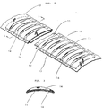
- Fig. 2 is a partly broken perspective view showing a construction of a cloth slat for use in one example of the blind according to the present invention.
- Fig. 3 is a sectional view taken along a line A-A in Fig. 2.
- Fig. 4 is a diagrammatic side view showing an apparatus for manufacturing the cloth slat according to the present invention.
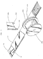
- Fig. 5 is a partly enlarged view illustrating a welding apparatus and the cloth slat which has passed through the welding apparatus.
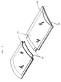
- Figs. 6-8 illustrate modified forms of the cloth blind slat.
- Figs. 2 and 3 illustrate a blind slat used in one embodiment of the present invention.
- the blind slat according to the present invention is characterized by a slat body covered with a cloth casing having wrinkles.
- Fig. 2 designates a slat body of the blind slat according to the present invention which is made of an aluminum thin plate.
- the size and the shape of the slat body may be same as that of the conventional blind slat.
- the slat body is formed in slightly curved shape upwardly.
- the side edge portions of the casing at both sides of the slat body are wrinkled in longitudinal direction and welded to the slat body at points 13 closely spaced apart along the side edges.
- raised wrinkles 14 are formed in widthwise direction of the slat body, as shown in Fig. 3.
- hollow air layer portions are formed in the wrinkles 14 and the blind slat presents an appearance of cloth having wrinkles at distances of few millimeters.
- the cloth slat After forming the wrinkles, the cloth slat is subjected to finishing process and formed with through-holes which allow the lifting/lowering cords to pass therethrough.
- the cloth slat thus formed is used to constitute the blind as shown in Fig. 1.
- the wrinkles are arranged at equal intervals in the illustrated example, but these wrinkles may be arranged at smaller intervals near the longitudinally end areas and at larger intervals at the central area.
- the sizes of the wrinkles may be varied so as to correspond to patterns printed on the cloth casing.
- Fig. 4 shows one example of the construction of the apparatus for manufacturing the cloth blind according to the present invention.
- the apparatus shown in Fig. 4 comprises a first feeding means for feeding a strip material 15 of aluminum thin plate including a roll 15a of said strip material and unwinding rolls 15b for unwinding the strip material from the roll 15a; a second feeding means for feeding an upper side elongated cloth sheet 16 including a roll 16a of said material and unwinding rolls 16b for unwinding the cloth sheet 16 from the roll 16a; and a third feeding means for feeding a lower side elongated cloth sheet 17 including a roll 17a of said material and unwinding rolls 17b for unwinding the cloth sheet 17 from the roll 17a.
- These feeding means constitute an unwinding mechanism for unwinding the above-mentioned three sheets.
- the feeding speed of the feeding roll 16a which forms the feeding means for feeding the upper side cloth sheet 16 is set at a faster speed than the feeding speeds of the other feeding rolls 15a and 17a and the three sheets unwound from the feeding rolls 15a, 16a and 17a are integrated into a stacked assembly at an assembling roll 18 to form an assembly including the aluminum thin plate and the elongated cloth sheets in which the side margins of the cloth sheets 16 and 17 are aligned with each other and the side edge portions of the cloth sheets extend beyond the side edges of the aluminum thin plate 15.
- the assembly of these cloth sheets and the aluminum thin plate are conveyed toward a slat winding roll 19.
- the welding apparatus includes a welding roll 20a disposed at one side of the path of the assembled slat and a welder 20b disposed at the other side of said path.
- the welding roll 20a has series of electrodes 20c which are intermittently disposed along both sides of said welding roll in circumferential direction at equal intervals, while the welder 20b has counterelectrodes 20d.
- the respective pairs of the electrodes 20c and the counterelectrodes serve to intermittently weld the cloth sheets and the aluminum thin plate together.
- the rotary speed of the welding roll 20a is set so that the upper side cloth sheet 16 is fed at slightly higher speed than the aluminum thin plate 15 to form the wrinkles in the upper side cloth sheet 16 owing to the conveying speed of the welding roll 20a and the set position thereof.
- the welder 20b is constructed in movable type so that said welder can intermittently move into contact with the assembled slat material or move away therefrom.
- the hollow air layers are formed in the wrinkle portions of the cloth slat.
- This cloth slat presents a novel and beautiful appearance having wrinkles spaced apart by few millimeters.
- the cloth slat thus formed by the process shown in Figs. 4 and 5 is cut to desired lengths and subjected to a finishing process for finishing the longitudinal ends and the both portions of the slat. Then it is subjected to hole forming process.
- the cloth slats thus formed are assembled into the form of the horizontal type blind.
- the cloth blind slat according to the present invention may be modified in various forms. Some examples of the modification are shown in Figs. 6-8.
- Fig. 6 illustrates an embodiment in which an upper side cloth sheet 21 is welded to an aluminum thin plate 22 and a lower side cloth sheet 23 only at both side edges to form a hollow air layer 24 under the upper side cloth sheet.
- Fig. 7 illustrates an embodiment in which an upper side cloth sheet 25 is formed in a corrugated shape.
- Fig. 8 illustrates an embodiment in which an upper side cloth sheet 26 has raised patterns 27 under which hollow air layers are formed.
- the present invention provides a horizontal type blind which eliminates a problem of presenting a cold appearance of a blind including metallic slats and prevents an operator from being injured by a sharp edge of a metallic slat.
- the blind according to the present invention serves to not only provide a light controlling effect but also provide a temperature-holding and heat-insulating effect as well as a sound-insulating effect, owing to the presence of the air layer under the cloth casing.
- the casing is easily removable from the slat, so that when the slat becomes dirty the casing can be easily removed and washed.
Landscapes
- Engineering & Computer Science (AREA)
- Mechanical Engineering (AREA)
- Structural Engineering (AREA)
- Architecture (AREA)
- Civil Engineering (AREA)
- Blinds (AREA)
- Manufacturing And Processing Devices For Dough (AREA)
- Auxiliary Devices For And Details Of Packaging Control (AREA)
- Warehouses Or Storage Devices (AREA)
- Operating, Guiding And Securing Of Roll- Type Closing Members (AREA)
- Laminated Bodies (AREA)
Abstract
Description
- The present invention relates to a cloth blind and a method and an apparatus for manufacturing a blind slat of the cloth blind. Particularly, it relates a cloth blind having characteristic feature in a shape and a construction of the blind slat and a method and an apparatus for manufacturing such blind slat.
- Fig. 1 illustrates a general construction of a conventional horizontal type blind.
- As well known in the art, the horizontal type blind comprises a
headbox 1, a plurality ofblind slats 2, each consisting of a narrow thin plate,ladder cords 3 for supporting the slats at vertically spaced relation from each other and controlling tilting of the respective slats to adjust light shading effect of the blind, said ladder cords hanging from saidheadbox 1, and lifting/lowering cords 4 for lifting or lowering the slats. The lifting/lowering cords 4 are operated by anoperating cord 5 to open or close the blind and theladder cords 3 are operated by an operating rod to control tilting of the respective slats to adjust light shading effect of the blind. Arail 7 is arranged at the bottom of the group of the slats. - In the conventional horizontal type blind, each slat is an elongated and narrow thin plate having a width of about 10 - 50 mm and a length of about 300 - 3000 mm, in which at least two through-holes are formed to allow the lifting/lowering cords to pass therethrough. In order to provide the slat with sufficient strength, it has been the usual practice to use the slat made of a metallic material, typically an aluminum alloy.
- Such blind has been used as a light controlling instrument, for example in an office room. Recently, the blind of this kind plays an important role as an interior of a house and tends to be widely used in an individual home. According to such trend, slats of a plurality of colors have been developed.
- On the other hand, the blind having slats made of metallic material has such disadvantage that the blind presents a cold appearance, owing to the metallic color and luster of the slats, when it is used in an office. In order to avoid such disadvantage it has been proposed to cover the slat with a bag-shaped soft cover. (Japanese Utility Model Publication No. Sho 52-56001, Japanese Utility Model Application Laid-Open No. Sho 62-21298).
- As explained above, the conventional blind, using metallic slats, provides mechanically and functionally good effect, but it presents a cold appearance. Such disadvantage can be overcome by covering the metallic slat with the bag-shaped soft cover, which presents a warm appearance. However, such soft cover only serves to improve the feeling of the blind and cannot provide a temperature-holding and heat-insulating property and a sound-insulating property, such as attained by a cloth curtain or the like.
- US Patent Specifications Nos. 4,884,615 and 4,930,562 both disclose methods of making blind slats.
- It is a concern of the present invention to eliminate the disadvantage of the conventional blind which presents a cold appearance owing to the metallic slats.
- It is another concern of the present invention to provide a cloth blind which produces a heat insulating effect, in addition to a light controlling effect, and which can be advantageously used, as a window light controlling instrument, in a cold district or a cold season.
- It is a further concern of the present invention to provide a cloth blind in which a metallic slat is covered with a cloth casing, which serves to prevent an operator's body, such as hand, from being injured by a sharp edge of the metallic slat and which presents a novel appearance and a unique ornamental effect to the blind.
- It is a further concern of the present invention to provide a method and an apparatus for manufacturing the cloth blind as mentioned above in effective manner at a low cost.
- In accordance with one aspect of the present invention there is provided a method of manufacturing a blind slat as set out in
claim 1. - In accordance with a second aspect of the invention there is provided apparatus for manufacturing blind slats as set out in
claim 6. - In order that the present invention may be more readily understood, an embodiment of the invention will now be described by way of example and with reference to the accompanying drawings, in which:
- Fig. 1 is a perspective view illustrating a general arrangement of a blind according to a prior art.
- Fig. 2 is a partly broken perspective view showing a construction of a cloth slat for use in one example of the blind according to the present invention.
- Fig. 3 is a sectional view taken along a line A-A in Fig. 2.
- Fig. 4 is a diagrammatic side view showing an apparatus for manufacturing the cloth slat according to the present invention.
- Fig. 5 is a partly enlarged view illustrating a welding apparatus and the cloth slat which has passed through the welding apparatus.
- Figs. 6-8 illustrate modified forms of the cloth blind slat.
- Now the invention will be explained with reference to the preferred embodiments shown in the drawings.
- Figs. 2 and 3 illustrate a blind slat used in one embodiment of the present invention. As shown in these drawings, the blind slat according to the present invention is characterized by a slat body covered with a cloth casing having wrinkles.
- In Fig. 2, 11 designates a slat body of the blind slat according to the present invention which is made of an aluminum thin plate. The size and the shape of the slat body may be same as that of the conventional blind slat. In the illustrated example, the slat body is formed in slightly curved shape upwardly.
- 12 designates a cloth casing which covers the aluminum slat body. The size of this cloth casing is larger than that of the slat body, so that the cloth casing is allowed to form wrinkle on the slat body.
- In the illustrated example, after the
slat body 11 has been inserted into theelongated casing 12, the side edge portions of the casing at both sides of the slat body are wrinkled in longitudinal direction and welded to the slat body atpoints 13 closely spaced apart along the side edges. Thus, raisedwrinkles 14 are formed in widthwise direction of the slat body, as shown in Fig. 3. - According to this construction, hollow air layer portions are formed in the
wrinkles 14 and the blind slat presents an appearance of cloth having wrinkles at distances of few millimeters. - After forming the wrinkles, the cloth slat is subjected to finishing process and formed with through-holes which allow the lifting/lowering cords to pass therethrough. The cloth slat thus formed is used to constitute the blind as shown in Fig. 1.
- The wrinkles are arranged at equal intervals in the illustrated example, but these wrinkles may be arranged at smaller intervals near the longitudinally end areas and at larger intervals at the central area. The sizes of the wrinkles may be varied so as to correspond to patterns printed on the cloth casing.
- The method and the apparatus for manufacturing the cloth blind according to the present invention will be explained with reference to Figs. 4 and 5, which illustrate an embodiment of the apparatus for manufacturing a cloth blind, according to the present invention.
- Fig. 4 shows one example of the construction of the apparatus for manufacturing the cloth blind according to the present invention.
- The apparatus shown in Fig. 4 comprises a first feeding means for feeding a
strip material 15 of aluminum thin plate including aroll 15a of said strip material and unwindingrolls 15b for unwinding the strip material from theroll 15a; a second feeding means for feeding an upper sideelongated cloth sheet 16 including a roll 16a of said material and unwindingrolls 16b for unwinding thecloth sheet 16 from the roll 16a; and a third feeding means for feeding a lower sideelongated cloth sheet 17 including a roll 17a of said material and unwindingrolls 17b for unwinding thecloth sheet 17 from the roll 17a. These feeding means constitute an unwinding mechanism for unwinding the above-mentioned three sheets. - The feeding speed of the feeding roll 16a which forms the feeding means for feeding the upper
side cloth sheet 16 is set at a faster speed than the feeding speeds of theother feeding rolls 15a and 17a and the three sheets unwound from thefeeding rolls 15a, 16a and 17a are integrated into a stacked assembly at an assemblingroll 18 to form an assembly including the aluminum thin plate and the elongated cloth sheets in which the side margins of thecloth sheets thin plate 15. The assembly of these cloth sheets and the aluminum thin plate are conveyed toward aslat winding roll 19. - On the way from the assembling
roll 18 to theslat winding roll 19, awelding apparatus 20 is arranged. The welding apparatus includes awelding roll 20a disposed at one side of the path of the assembled slat and awelder 20b disposed at the other side of said path. Thewelding roll 20a has series ofelectrodes 20c which are intermittently disposed along both sides of said welding roll in circumferential direction at equal intervals, while thewelder 20b hascounterelectrodes 20d. The respective pairs of theelectrodes 20c and the counterelectrodes serve to intermittently weld the cloth sheets and the aluminum thin plate together. - The rotary speed of the
welding roll 20a is set so that the upperside cloth sheet 16 is fed at slightly higher speed than the aluminumthin plate 15 to form the wrinkles in the upperside cloth sheet 16 owing to the conveying speed of thewelding roll 20a and the set position thereof. Preferably, thewelder 20b is constructed in movable type so that said welder can intermittently move into contact with the assembled slat material or move away therefrom. - By the method and the apparatus for manufacturing the cloth slat as described above, the hollow air layers are formed in the wrinkle portions of the cloth slat. This cloth slat presents a novel and beautiful appearance having wrinkles spaced apart by few millimeters.
- The cloth slat thus formed by the process shown in Figs. 4 and 5 is cut to desired lengths and subjected to a finishing process for finishing the longitudinal ends and the both portions of the slat. Then it is subjected to hole forming process. The cloth slats thus formed are assembled into the form of the horizontal type blind.
- It is preferable to provide a mechanism for adjusting the rotary speed of the feeding rolls to vary the distance between the wrinkles, sizes of the wrinkles or the like.
- The cloth blind slat according to the present invention may be modified in various forms. Some examples of the modification are shown in Figs. 6-8.
- Fig. 6 illustrates an embodiment in which an upper
side cloth sheet 21 is welded to an aluminumthin plate 22 and a lowerside cloth sheet 23 only at both side edges to form ahollow air layer 24 under the upper side cloth sheet. - Fig. 7 illustrates an embodiment in which an upper
side cloth sheet 25 is formed in a corrugated shape. - Fig. 8 illustrates an embodiment in which an upper
side cloth sheet 26 has raisedpatterns 27 under which hollow air layers are formed. - It will be understood that the present invention provides a horizontal type blind which eliminates a problem of presenting a cold appearance of a blind including metallic slats and prevents an operator from being injured by a sharp edge of a metallic slat. Furthermore, the blind according to the present invention serves to not only provide a light controlling effect but also provide a temperature-holding and heat-insulating effect as well as a sound-insulating effect, owing to the presence of the air layer under the cloth casing. The casing is easily removable from the slat, so that when the slat becomes dirty the casing can be easily removed and washed.
Claims (7)
- A method of manufacturing a blind slat for a blind comprising:longitudinally feeding a strip of material (15); andfeeding a pair of elongated cloth sheets (16,17) into contact with the respective upper and lower surfaces of the strip material;and characterised in that at least one of the cloth sheets is fed at a higher rate than the strip material; securing portions of the cloth sheets to the strip material; and cutting the cloth sheets and strip material to predetermined lengths to form blind slats.
- A method according to claim 1, and further characterised in that only one cloth sheet is fed at a higher rate than the strip material.
- A method according to claim 2, and further characterised in that the feeding rate of said one cloth sheet is between 1.2 to 1.5 times higher than that of the strip material.
- A method according to any one of the preceding claims and characterised in that the cloth sheets are wider than the strip material and in that edge portions of the cloth sheets are intermittently fixed to the strip material.
- A method as claimed in claim 4 and still further characterised in that the cloth sheets are intermittently welded to the strip material.
- Apparatus for manufacturing blind slats in accordance with the method of claim 1 and characterised in that it comprises:first feeding means (15b) for feeding a strip of material;second and third feeding means (16b,17b) for feeding elongated cloth sheets into contact with the respective upper and lower surfaces of the strip material;conveying means for conveying the assembly formed by the respective layers of cloth and strip material; andfixing means for securing the cloth sheets to the strip material;and still further characterised in that at least one of the second or third feeding means feeds its associated elongated cloth sheet at a rate higher than that of the feeding means for the strip material.
- Apparatus according to claim 6 and further characterised in that said fixing means comprises a welder (20b).
Applications Claiming Priority (4)
| Application Number | Priority Date | Filing Date | Title |
|---|---|---|---|
| JP205468/90 | 1990-08-01 | ||
| JP20546890A JPH0768834B2 (en) | 1990-08-01 | 1990-08-01 | Fabric blinds |
| JP20968790A JPH0768835B2 (en) | 1990-08-09 | 1990-08-09 | Method and device for manufacturing cloth slats |
| JP209687/90 | 1990-08-09 |
Publications (2)
| Publication Number | Publication Date |
|---|---|
| EP0469695A1 EP0469695A1 (en) | 1992-02-05 |
| EP0469695B1 true EP0469695B1 (en) | 1996-04-24 |
Family
ID=26515078
Family Applications (1)
| Application Number | Title | Priority Date | Filing Date |
|---|---|---|---|
| EP19910301438 Expired - Lifetime EP0469695B1 (en) | 1990-08-01 | 1991-02-22 | Blind and slat therefor, method and apparatus for making same |
Country Status (3)
| Country | Link |
|---|---|
| EP (1) | EP0469695B1 (en) |
| AT (1) | ATE137303T1 (en) |
| DE (1) | DE69118988T2 (en) |
Families Citing this family (7)
| Publication number | Priority date | Publication date | Assignee | Title |
|---|---|---|---|---|
| US5749404A (en) * | 1995-05-10 | 1998-05-12 | Hunter Douglas Inc. | Fabric for an architectural covering and method and apparatus of manufacturing same |
| US5797442A (en) * | 1995-05-10 | 1998-08-25 | Hunter Douglas Inc. | Vane for an architectural covering and method of making same |
| AUPN469195A0 (en) * | 1995-08-08 | 1995-08-31 | Zorbas, Tass | A fabric blind |
| GB2424917B (en) * | 2005-03-29 | 2008-11-26 | Nien Made Entpr Co Ltd | Slat for a blind |
| USD643238S1 (en) | 2009-09-09 | 2011-08-16 | Hunter Douglas Inc. | Dual segmented covering for architectural openings |
| USD662747S1 (en) | 2011-03-05 | 2012-07-03 | Hunter Douglas Inc. | Shade assembly |
| GB2511053B (en) | 2013-02-20 | 2017-09-20 | Orangebox Ltd | A ceiling panel |
Family Cites Families (4)
| Publication number | Priority date | Publication date | Assignee | Title |
|---|---|---|---|---|
| JPS6221298U (en) * | 1985-07-22 | 1987-02-07 | ||
| US4884615A (en) * | 1988-09-27 | 1989-12-05 | Hsu Henry C | Sound absorbent slats for window blinds |
| EP0370120A1 (en) * | 1988-11-21 | 1990-05-30 | Ryh Jinn Metals Industry Co., Ltd. | Cloth covered blade for transverse type venetian blind |
| US4930562A (en) * | 1989-03-10 | 1990-06-05 | Hunter Douglas Inc. | Decoratively covered blind structure |
-
1991
- 1991-02-22 DE DE69118988T patent/DE69118988T2/en not_active Expired - Fee Related
- 1991-02-22 EP EP19910301438 patent/EP0469695B1/en not_active Expired - Lifetime
- 1991-02-22 AT AT91301438T patent/ATE137303T1/en not_active IP Right Cessation
Also Published As
| Publication number | Publication date |
|---|---|
| DE69118988T2 (en) | 1996-09-12 |
| EP0469695A1 (en) | 1992-02-05 |
| DE69118988D1 (en) | 1996-05-30 |
| ATE137303T1 (en) | 1996-05-15 |
Similar Documents
| Publication | Publication Date | Title |
|---|---|---|
| EP0553888B1 (en) | An expandable window covering | |
| EP0654577B1 (en) | Window shade | |
| US6189592B1 (en) | Roll up shade doubled fabric having patterns thereon | |
| US5339882A (en) | Venetian-type window covering | |
| US5664613A (en) | Light control window covering | |
| US6033504A (en) | Material for venetian type blinds | |
| DE69605388T2 (en) | IMPROVED SLEEVE FOR AN INTERIOR COVERING AND METHOD FOR PRODUCING IT | |
| US6761782B2 (en) | Method of treating ends of a fabric for a covering for architectural openings | |
| EP0482794B1 (en) | Expandable and collapsible window covering | |
| EP0427477B1 (en) | Improved roman shades | |
| US10526841B2 (en) | Cellular material for window coverings and method of making same | |
| US6598650B1 (en) | Hollow, rigid vanes for door and window coverings | |
| CA2106886C (en) | Adjustable expandable and collapsible shade | |
| CA2210283A1 (en) | Roll-up door with low friction edges | |
| GB2221944A (en) | Foldable roman blind. | |
| EP0469695A1 (en) | Blind and slat therefor, method and apparatus for making same | |
| EP0004455B1 (en) | Selectively collapsible and expandable curtain and its method of manufacture | |
| US20030029577A1 (en) | Light-control window covering and method and apparatus for its manufacture | |
| GB2236551A (en) | Single web, cellular concertina blind | |
| US6513565B1 (en) | Light controlling cellular shade and method of making same | |
| JP2022029217A (en) | Ladder tape for blind and method of manufacturing the same | |
| JP5069068B2 (en) | Blind slats | |
| JPH0396591A (en) | Slat for blind and manufacture thereof | |
| JPH0768835B2 (en) | Method and device for manufacturing cloth slats | |
| JPH0768834B2 (en) | Fabric blinds |
Legal Events
| Date | Code | Title | Description |
|---|---|---|---|
| PUAI | Public reference made under article 153(3) epc to a published international application that has entered the european phase |
Free format text: ORIGINAL CODE: 0009012 |
|
| AK | Designated contracting states |
Kind code of ref document: A1 Designated state(s): AT BE CH DE ES FR GB IT LI LU NL SE |
|
| 17P | Request for examination filed |
Effective date: 19920731 |
|
| 17Q | First examination report despatched |
Effective date: 19931130 |
|
| RAP1 | Party data changed (applicant data changed or rights of an application transferred) |
Owner name: KABUSHIKI KAISHA NICHIBEI |
|
| GRAA | (expected) grant |
Free format text: ORIGINAL CODE: 0009210 |
|
| AK | Designated contracting states |
Kind code of ref document: B1 Designated state(s): AT BE CH DE ES FR GB IT LI LU NL SE |
|
| PG25 | Lapsed in a contracting state [announced via postgrant information from national office to epo] |
Ref country code: LI Effective date: 19960424 Ref country code: ES Free format text: THE PATENT HAS BEEN ANNULLED BY A DECISION OF A NATIONAL AUTHORITY Effective date: 19960424 Ref country code: CH Effective date: 19960424 Ref country code: BE Effective date: 19960424 Ref country code: AT Effective date: 19960424 |
|
| REF | Corresponds to: |
Ref document number: 137303 Country of ref document: AT Date of ref document: 19960515 Kind code of ref document: T |
|
| REF | Corresponds to: |
Ref document number: 69118988 Country of ref document: DE Date of ref document: 19960530 |
|
| ET | Fr: translation filed | ||
| ITF | It: translation for a ep patent filed | ||
| PG25 | Lapsed in a contracting state [announced via postgrant information from national office to epo] |
Ref country code: SE Effective date: 19960724 |
|
| REG | Reference to a national code |
Ref country code: CH Ref legal event code: PL |
|
| PG25 | Lapsed in a contracting state [announced via postgrant information from national office to epo] |
Ref country code: LU Free format text: LAPSE BECAUSE OF NON-PAYMENT OF DUE FEES Effective date: 19970228 |
|
| PLBE | No opposition filed within time limit |
Free format text: ORIGINAL CODE: 0009261 |
|
| STAA | Information on the status of an ep patent application or granted ep patent |
Free format text: STATUS: NO OPPOSITION FILED WITHIN TIME LIMIT |
|
| 26N | No opposition filed | ||
| REG | Reference to a national code |
Ref country code: GB Ref legal event code: IF02 |
|
| PGFP | Annual fee paid to national office [announced via postgrant information from national office to epo] |
Ref country code: NL Payment date: 20050214 Year of fee payment: 15 |
|
| PGFP | Annual fee paid to national office [announced via postgrant information from national office to epo] |
Ref country code: GB Payment date: 20050215 Year of fee payment: 15 |
|
| PGFP | Annual fee paid to national office [announced via postgrant information from national office to epo] |
Ref country code: FR Payment date: 20050224 Year of fee payment: 15 |
|
| PGFP | Annual fee paid to national office [announced via postgrant information from national office to epo] |
Ref country code: DE Payment date: 20050331 Year of fee payment: 15 |
|
| PG25 | Lapsed in a contracting state [announced via postgrant information from national office to epo] |
Ref country code: GB Free format text: LAPSE BECAUSE OF NON-PAYMENT OF DUE FEES Effective date: 20060222 |
|
| PGFP | Annual fee paid to national office [announced via postgrant information from national office to epo] |
Ref country code: IT Payment date: 20060228 Year of fee payment: 16 |
|
| PG25 | Lapsed in a contracting state [announced via postgrant information from national office to epo] |
Ref country code: NL Free format text: LAPSE BECAUSE OF NON-PAYMENT OF DUE FEES Effective date: 20060901 Ref country code: DE Free format text: LAPSE BECAUSE OF NON-PAYMENT OF DUE FEES Effective date: 20060901 |
|
| GBPC | Gb: european patent ceased through non-payment of renewal fee |
Effective date: 20060222 |
|
| NLV4 | Nl: lapsed or anulled due to non-payment of the annual fee |
Effective date: 20060901 |
|
| REG | Reference to a national code |
Ref country code: FR Ref legal event code: ST Effective date: 20061031 |
|
| PG25 | Lapsed in a contracting state [announced via postgrant information from national office to epo] |
Ref country code: FR Free format text: LAPSE BECAUSE OF NON-PAYMENT OF DUE FEES Effective date: 20060228 |
|
| PG25 | Lapsed in a contracting state [announced via postgrant information from national office to epo] |
Ref country code: IT Free format text: LAPSE BECAUSE OF NON-PAYMENT OF DUE FEES Effective date: 20070222 |