EP0469672A2 - Rotating cutting tool - Google Patents
Rotating cutting tool Download PDFInfo
- Publication number
- EP0469672A2 EP0469672A2 EP91201928A EP91201928A EP0469672A2 EP 0469672 A2 EP0469672 A2 EP 0469672A2 EP 91201928 A EP91201928 A EP 91201928A EP 91201928 A EP91201928 A EP 91201928A EP 0469672 A2 EP0469672 A2 EP 0469672A2
- Authority
- EP
- European Patent Office
- Prior art keywords
- tool
- contact
- convex
- cutting
- central area
- Prior art date
- Legal status (The legal status is an assumption and is not a legal conclusion. Google has not performed a legal analysis and makes no representation as to the accuracy of the status listed.)
- Granted
Links
Images

Classifications
-
- B—PERFORMING OPERATIONS; TRANSPORTING
- B23—MACHINE TOOLS; METAL-WORKING NOT OTHERWISE PROVIDED FOR
- B23C—MILLING
- B23C5/00—Milling-cutters
- B23C5/16—Milling-cutters characterised by physical features other than shape
- B23C5/20—Milling-cutters characterised by physical features other than shape with removable cutter bits or teeth or cutting inserts
- B23C5/22—Securing arrangements for bits or teeth or cutting inserts
- B23C5/2204—Securing arrangements for bits or teeth or cutting inserts with cutting inserts clamped against the walls of the recess in the cutter body by a clamping member acting upon the wall of a hole in the insert
- B23C5/2208—Securing arrangements for bits or teeth or cutting inserts with cutting inserts clamped against the walls of the recess in the cutter body by a clamping member acting upon the wall of a hole in the insert for plate-like cutting inserts
- B23C5/2213—Securing arrangements for bits or teeth or cutting inserts with cutting inserts clamped against the walls of the recess in the cutter body by a clamping member acting upon the wall of a hole in the insert for plate-like cutting inserts having a special shape
-
- B—PERFORMING OPERATIONS; TRANSPORTING
- B23—MACHINE TOOLS; METAL-WORKING NOT OTHERWISE PROVIDED FOR
- B23C—MILLING
- B23C2200/00—Details of milling cutting inserts
- B23C2200/04—Overall shape
- B23C2200/0416—Irregular
-
- B—PERFORMING OPERATIONS; TRANSPORTING
- B23—MACHINE TOOLS; METAL-WORKING NOT OTHERWISE PROVIDED FOR
- B23C—MILLING
- B23C2200/00—Details of milling cutting inserts
- B23C2200/16—Supporting or bottom surfaces
- B23C2200/161—Supporting or bottom surfaces with projections
-
- B—PERFORMING OPERATIONS; TRANSPORTING
- B23—MACHINE TOOLS; METAL-WORKING NOT OTHERWISE PROVIDED FOR
- B23C—MILLING
- B23C2210/00—Details of milling cutters
- B23C2210/16—Fixation of inserts or cutting bits in the tool
- B23C2210/168—Seats for cutting inserts, supports for replacable cutting bits
Definitions
- the invention relates to a rotating, cutting tool for high-speed machining with one or more interchangeable cutting inserts fastened on a tool base body or a tool cassette and with contact surfaces located on the tool base body and on the cutting insert with a convex or concave central region and at least on one side adjacent flat edge regions for receiving the centrifugal forces occurring on the cutting inserts through the tool body.
- Rotating, cutting tools for high-speed machining such as high-speed milling cutters or high-speed drills, have high speeds that can reach up to 100,000 revolutions per minute. These high speeds result in very high centrifugal forces on the tool, which put extreme strain on the tool parts. Due to these high centrifugal forces, it is no longer possible to connect indexable inserts with a flat contact surface to the tool base body or a tool cassette only by means of a clamp or screws, since the permissible stress on the fasteners is exceeded by the centrifugal forces.
- indexable insert shapes have become known, the contact surface of which has a spring which engages in a corresponding groove in the contact surface of the basic tool body.
- a construction leads to very high stresses on the tool base body, especially in the area of the groove base due to the notch effect.
- the contact surfaces of the indexable inserts have a V-shaped contact surface which engages in a corresponding groove in the basic tool body.
- a disadvantage of such an embodiment is that the indexable inserts are only insufficiently and not precisely defined in the groove due to the high centrifugal forces and can tilt laterally.
- DE-OS 35 33 125 describes a further embodiment of a positive connection between the indexable inserts and the tool body.
- the contact surfaces of the indexable inserts and the contact surfaces of the tool body have teeth that are in engagement with one another, the teeth of which run parallel to the milling cutter axis and have a specific flank angle.
- the disadvantage of such an embodiment is that there is overdetermination due to the large number of system contacts, as a result of which no clear positioning of the indexable insert in the basic tool body is guaranteed.
- the object of the invention is therefore to provide a rotating, cutting tool for high-speed machining, in which the cutting inserts have a positive connection with the tool base body or the tool cassette, without overdetermination in the system, so that a defined positioning the cutting inserts is made possible and without mechanical overloading occurring on the cutting inserts, fastening elements or on parts of the basic tool body.
- this is achieved in that the tool body and cutting insert, seen in section, are in contact with each other at three contact points on both contact surfaces, two contact points lying within the central areas and the third contact point lying within the flat peripheral areas, and that the convex central area of the contact surface is at least in the area of the two contact points is the section of the lateral surface of a circular cylinder which extends at least approximately in the direction of the axis of rotation over the entire central region.
- the inventive design ensures that the cutting inserts can be pivoted relative to the tool body along the central areas of the common contact surfaces, so that even with manufacturing tolerances, a flat edge area of the cutting insert can be safely brought into contact with the corresponding flat edge area of the tool body. This ensures an exact, backlash-free form fit with a defined positioning of the cutting inserts. The centrifugal and cutting forces that occur are absorbed without excessive stress on the individual tool components and without changing the position of the cutting inserts.
- the convex central region of the contact surface is always designed as a section of the circumferential surface of a circular cylinder, at least in the region of the two contact points, the configuration of the concave central region can be varied.
- the concave central region can also be part of the circumferential surface of a circular cylinder, but it can also be the section of an elliptical, parabolic or hyperbolic cylinder or a U- or V-shaped groove.
- the convex central area can either be incorporated in the cutting insert or in the tool base body or in the tool cassette.
- the flat edge areas can adjoin one or both sides of the convex or concave central area.
- the cutting inserts can be designed as disposable inserts or as indexable inserts with or without a central hole for fastening by means of clamping screws or using clamping claws.
- the contact surfaces of the cutting inserts can be produced simply and cheaply by direct pressing and, if necessary, simple form grinding.
- the contact surfaces in the basic tool body or in the tool cassette can be milled, ground or eroded at low cost using simple technical means.
- the tools according to the invention can be used rotating at high speeds for high-speed milling or high-speed drilling.
- indexable inserts and tool base body or tool cassette are designed such that two contact points lie within the convex central area and in the immediate transition from the concave central area to the flat edge areas.
- the concave central region of the contact surface is the section of the lateral surface of a circular cylinder, the radius of the lateral surface being smaller than the radius of the lateral surface of the convex central region of the contact surface.
- This special configuration achieves a particularly simple and inexpensive manufacture of the central areas.
- the convex central region of the contact surface is designed on the cutting inserts. This reduces the risk of cutting insert breakage, which is significantly greater in the case of cutting inserts due to the dimensions and the material, than with the tool base body.
- the size of the elevation h of the convex or concave central regions of the contact surfaces is in a range between 1/5 and 1/10 of the diameter of the convex central region of the contact surface. This ensures a secure form fit even under extreme loads.
- the secure clamping of the cutting inserts if they have a center hole and are screwed to the tool base body or the tool cassette via clamping screws, the longitudinal axis of the center hole and the longitudinal axis of the threaded bore in the tool base body being inclined at an angle to one another. In this way it is achieved that the cutting inserts rest against three points in a defined manner even under cutting conditions. It is of course advantageous to choose the inclination so that the flat edge areas come to rest, which are at the cutting edges of the cutting inserts that are in the cutting insert.
- the cutting inserts for a tool according to the invention are advantageously each designed as a center-hole indexable insert, the contact surface of which, when seen in section, each has two lateral, flat edge regions, and the convex central region, adjacent to the flat edge regions, has two lateral surface sections of a circular cylinder, which cut into a central flat surface pass over.
- a sufficient possibility of pivoting the indexable insert with respect to the tool base body for producing a safe three-point system is achieved via the circular-cylindrical jacket sections, while the central surface simultaneously provides a good contact surface for grinding on the circumference when producing the indexable insert.
- the cutting tool according to the invention for high-speed machining consists of a shaft-shaped base body -1- and two center-hole indexable inserts -2- which are fastened in recesses in the base body -1- by screws -7-.
- the contact surface -4- of the indexable inserts -2- consists of a convex central area - 4b-, which is formed as part of the circumferential surface of a circular cylinder, and of two lateral flat edge areas -4a-, which are arranged perpendicular to the axis of symmetry -S4- of the convex central area -4b-.
- the corresponding contact surface -5- of the main tool body -3- consists of a concave central area -5b-, which is also formed as part of the circumferential surface of a circular cylinder and of two lateral, flat edge areas -5a- which are perpendicular to the axis of symmetry -S5- of the concave Central area are arranged -5b.
- the radius of the concave central area -5b- of this contact surface -5- is slightly smaller than the radius of the convex central area -4b- of the contact surface -4- of the indexable inserts -2-. It is thereby achieved that the convex central region -4b- of the contact surface -4- of each indexable insert -2-defines at two punctiform or small-area locations at the direct transition from the concave central region -5b- to the lateral flat edge regions -5a- of the tool base body -3 - is present.
- indexable insert -2- is tilted to the side, there is also a flat edge region -4a- of the contact surface -4- of the indexable insert -2- on the corresponding flat edge region -5a- of the contact surface -5- of the tool base body -3-. It is important here that the indexable insert -2- is tilted in such a way that the flat edge regions -4a lying closer to the circumference of the tool come to rest on the flat edge region -5a- of the contact surface -5- of the tool base body -3-.
- the threaded hole -9- in the tool base -3- for fastening the center hole insert -2- is incorporated with a screw -7- in such a way that the longitudinal axis -10- of the threaded hole -9- to the longitudinal axis -8- of the center hole of the insert -2- is inclined inwards at an acute angle from the circumference of the tool. If the indexable insert -2- is fastened to the tool base body -3- by means of the screw -7-, a defined, safe 3-point system is obtained which is also retained during the machining process.
Abstract
Description
Die Erfindung betrifft ein rotierendes, spanabhebendes Werkzeug für die Hochgeschwindigkeitsbearbeitung mit einem oder mehreren auf einem Werkzeuggrundkörper oder einer Werkzeugkassette befestigten auswechselbaren Schneideinsätzen und mit am Werkzeuggrundkörper und am Schneideinsatz befindlichen Anlageflächen mit einem konvexen bzw. konkaven Zentralbereich und zumindest einseitig daran angrenzenden ebenen Randbereichen zur Aufnahme der an den Schneideinsätzen auftretenden Fliehkräfte durch den Werkzeuggrundkörper.The invention relates to a rotating, cutting tool for high-speed machining with one or more interchangeable cutting inserts fastened on a tool base body or a tool cassette and with contact surfaces located on the tool base body and on the cutting insert with a convex or concave central region and at least on one side adjacent flat edge regions for receiving the centrifugal forces occurring on the cutting inserts through the tool body.
Bei rotierenden, spanabhebenden Werkzeugen für die Hochgeschwindigkeitsbearbeitung, wie bei Hochgeschwindigkeitsfräsern oder Hochgeschwindigkeitsbohrern, treten hohe Drehzahlen auf, die bis zu 100.000 Umdrehungen pro Minute betragen können. Durch diese hohen Drehzahlen treten am Werkzeug sehr hohe Fliehkräfte auf, die die Werkzeugteile aufs Äußerste beanspruchen. Aufgrund dieser großen Fliehkräfte ist es nicht mehr möglich, Wendeschneidplatten mit einer ebenen Auflagefläche nur kraftschlüssig über eine Klemmbefestigung oder über Schrauben mit dem Werkzeuggrundkörper oder einer Werkzeugkassette zu verbinden, da die zulässige Beanspruchung der Befestigungsmittel durch die Fliehkräfte überschritten werden.Rotating, cutting tools for high-speed machining, such as high-speed milling cutters or high-speed drills, have high speeds that can reach up to 100,000 revolutions per minute. These high speeds result in very high centrifugal forces on the tool, which put extreme strain on the tool parts. Due to these high centrifugal forces, it is no longer possible to connect indexable inserts with a flat contact surface to the tool base body or a tool cassette only by means of a clamp or screws, since the permissible stress on the fasteners is exceeded by the centrifugal forces.
Man hat daher in der Vergangenheit für derartige Einsatzbedingungen versucht, eine spezifische Verbindung zwischen Wendeschneidplatten und Werkzeuggrundkörper oder Werkzeugkassette zu schaffen, um über diese spezifische Verbindung den Großteil der Fliehkräfte aufzunehmen und die Beanspruchung der Befestigungsmittel herabzusetzen.Attempts have therefore been made in the past for such operating conditions to create a specific connection between indexable inserts and tool base body or tool cassette in order to absorb the majority of the centrifugal forces via this specific connection and to reduce the stress on the fastening means.
Bekannt geworden sind dabei Wendeschneidplatten-Formen, deren Anlagefläche eine Feder aufweist, die in eine entsprechende Nut der Anlagefläche des Werkzeuggrundkörpers eingreift. Eine derartige Konstruktion führt jedoch zu sehr hohen Beanspruchungen des Werkzeuggrundkörpers, vor allem im Bereich des Nutengrundes durch Kerbwirkung.In this case, indexable insert shapes have become known, the contact surface of which has a spring which engages in a corresponding groove in the contact surface of the basic tool body. However, such a construction leads to very high stresses on the tool base body, especially in the area of the groove base due to the notch effect.
Bei einer anderen bekannten Ausführungsform weisen die Auflageflächen der Wendeschneidplatten eine V-förmige Anlagefläche auf, die in eine entsprechende Nut des Werkzeuggrundkörpers eingreift. Nachteilig bei einer derartigen Ausführung ist, daß die Wendeschneidplatten bei den hohen Fliehkräften nur unzureichend und nicht genau definiert in der Nut positioniert sind und seitlich verkippen können.In another known embodiment, the contact surfaces of the indexable inserts have a V-shaped contact surface which engages in a corresponding groove in the basic tool body. A disadvantage of such an embodiment is that the indexable inserts are only insufficiently and not precisely defined in the groove due to the high centrifugal forces and can tilt laterally.
In der DE-OS 35 33 125 ist eine weitere Ausführung einer formschlüssigen Verbindung zwischen den Wendeschneidplatten und dem Werkzeuggrundkörper beschrieben. Nach dieser Vorveröffentlichung weisen die Anlageflächen der Wendeschneidplatten und die Anlageflächen des Werkzeugkörpers miteinander in Eingriff stehende Verzahnungen auf, deren Zähne parallel zur Fräserachse verlaufen und einen bestimmten Flankenwinkel aufweisen. Der Nachteil einer derartigen Ausführung liegt darin, daß durch die Vielzahl der Anlagekontakte eine Überbestimmung vorliegt, wodurch keine eindeutige Positionierung der Wendeschneidplatte im Werkzeuggrundkörper mehr gewährleistet ist.DE-OS 35 33 125 describes a further embodiment of a positive connection between the indexable inserts and the tool body. According to this prior publication, the contact surfaces of the indexable inserts and the contact surfaces of the tool body have teeth that are in engagement with one another, the teeth of which run parallel to the milling cutter axis and have a specific flank angle. The disadvantage of such an embodiment is that there is overdetermination due to the large number of system contacts, as a result of which no clear positioning of the indexable insert in the basic tool body is guaranteed.
Die Aufgabe der Erfindung ist es daher, ein rotierendes, spanabhebendes Werkzeug für die Hochgeschwindigkeitsbearbeitung zu schaffen, bei dem die Schneideinsätze mit dem Werkzeuggrundkörper oder der Werkzeugkassette eine formschlüssige Verbindung aufweisen, ohne daß es zu einer Überbestimmung in der Anlage kommt, so daß eine definierte Positionierung der Schneideinsätze ermöglicht ist und ohne daß mechanische Überbeanspruchungen an den Schneideinsätzen, Befestigungselementen oder an Teilen des Werkzeuggrundkörpers auftreten.The object of the invention is therefore to provide a rotating, cutting tool for high-speed machining, in which the cutting inserts have a positive connection with the tool base body or the tool cassette, without overdetermination in the system, so that a defined positioning the cutting inserts is made possible and without mechanical overloading occurring on the cutting inserts, fastening elements or on parts of the basic tool body.
Erfindungsgemäß wird dies dadurch erreicht, daß im Schnitt gesehen Werkzeuggrundkörper und Schneideinsatz in drei Anlagepunkten auf beiden Anlageflächen Kontakt miteinander haben, wobei zwei Anlagepunkte innerhalb der Zentralbereiche liegen und der dritte Anlagepunkt innerhalb der ebenen Randbereiche liegt und daß der konvexe Zentralbereich der Anlagefläche zumindest im Bereich der zwei Anlagepunkte der Abschnitt der Mantelfläche eines Kreiszylinders ist, der sich zumindest annähernd in Richtung der Rotationsachse über den gesamten Zentralbereich erstreckt.According to the invention, this is achieved in that the tool body and cutting insert, seen in section, are in contact with each other at three contact points on both contact surfaces, two contact points lying within the central areas and the third contact point lying within the flat peripheral areas, and that the convex central area of the contact surface is at least in the area of the two contact points is the section of the lateral surface of a circular cylinder which extends at least approximately in the direction of the axis of rotation over the entire central region.
Durch die erfindungsgemäße Ausgestaltung wird erreicht, daß die Schneideinsätze gegenüber dem Werkzeuggrundkörper entlang der Zentralbereiche der gemeinsamen Anlageflächen verschwenkt werden können, so daß auch bei Fertigungstoleranzen ein ebener Randbereich des Schneideinsatzes sicher zur Anlage am entsprechenden ebenen Randbereich des Werkzeuggrundkörpers gebracht werden kann. Dadurch wird ein exakter, spielfreier Formschluß mit einer definierten Positionierung der Schneideinsätze gewährleistet. Die auftretenden Flieh- und Zerspanungskräfte werden ohne unzulässige Überbeanspruchung der einzelnen Werkzeugkomponenten und ohne Lageveränderung der Schneideinsätze aufgenommen.The inventive design ensures that the cutting inserts can be pivoted relative to the tool body along the central areas of the common contact surfaces, so that even with manufacturing tolerances, a flat edge area of the cutting insert can be safely brought into contact with the corresponding flat edge area of the tool body. This ensures an exact, backlash-free form fit with a defined positioning of the cutting inserts. The centrifugal and cutting forces that occur are absorbed without excessive stress on the individual tool components and without changing the position of the cutting inserts.
Während der konvexe Zentralbereich der Anlagefläche zumindest im Bereich der zwei Anlagepunkte immer als Abschnitt der Mantelfläche eines Kreiszylinders ausgeführt ist, kann die Ausgestaltung des konkaven Zentralbereiches vielgestaltig sein. So kann der konkave Zentralbereich ebenfalls ein Teil der Mantelfläche eines Kreiszylinders sein, er kann aber ebenso der Abschnitt eines ellipsenförmigen, parabelförmigen oder hyperbelförmigen Zylinders oder eine U- oder V-förmige Nut sein. Der konvexe Zentralbereich kann entweder im Schneideinsatz oder im Werkzeuggrundkörper bzw. in der Werkzeugkassette eingearbeitet sein. Die ebenen Randbereiche können an einer oder beiden Seiten des konvexen bzw. konkaven Zentralbereiches angrenzen.While the convex central region of the contact surface is always designed as a section of the circumferential surface of a circular cylinder, at least in the region of the two contact points, the configuration of the concave central region can be varied. The concave central region can also be part of the circumferential surface of a circular cylinder, but it can also be the section of an elliptical, parabolic or hyperbolic cylinder or a U- or V-shaped groove. The convex central area can either be incorporated in the cutting insert or in the tool base body or in the tool cassette. The flat edge areas can adjoin one or both sides of the convex or concave central area.
Die Schneideinsätze können als Wegwerfeinsätze oder als Wendeschneidplatten mit oder ohne Mittelloch zur Befestigung mittels Klemmschrauben oder über Klemmpratzen ausgeführt sein.The cutting inserts can be designed as disposable inserts or as indexable inserts with or without a central hole for fastening by means of clamping screws or using clamping claws.
Die Anlageflächen der Schneideinsätze können in erfindungsgemäßer Ausgestaltung einfach und billig durch Direktpressen und ggf. einfachen Formschliff hergestellt werden. Desgleichen können die Anlageflächen im Werkzeuggrundkörper bzw. in der Werkzeugkassette mit einfachen technischen Mitteln und kostengünstig gefräst, geschliffen oder erodiert werden.In the embodiment according to the invention, the contact surfaces of the cutting inserts can be produced simply and cheaply by direct pressing and, if necessary, simple form grinding. Likewise, the contact surfaces in the basic tool body or in the tool cassette can be milled, ground or eroded at low cost using simple technical means.
Die erfindungsgemäßen Werkzeuge können rotierend bei hohen Drehzahlen zum Hochgeschwindigkeitsfräsen oder Hochgeschwindigkeitsbohren eingesetzt werden.The tools according to the invention can be used rotating at high speeds for high-speed milling or high-speed drilling.
Besonders vorteilhaft ist es, wenn Wendeschneidplatten und Werkzeuggrundkörper bzw. Werkzeugkassette so ausgeführt werden, daß zwei Anlagepunkte innerhalb des konvexen Zentralbereiches sowie im unmittelbaren Übergang des konkaven Zentralbereiches zu den ebenen Randbereichen liegen.It is particularly advantageous if indexable inserts and tool base body or tool cassette are designed such that two contact points lie within the convex central area and in the immediate transition from the concave central area to the flat edge areas.
Auf diese Weise wird eine äußerst stabile definierte Anlage zwischen Wendeschneidplatte und Werkzeuggrundkörper erreicht.In this way, an extremely stable, defined contact between the insert and the tool body is achieved.
Weiters ist es vorteilhaft, wenn auch der konkave Zentralbereich der Anlagefläche der Abschnitt der Mantelfläche eines Kreiszylinders ist, wobei der Radius der Mantelfläche kleiner ist als der Radius der Mantelfläche des konvexen Zentralbereiches der Anlagefläche.Furthermore, it is advantageous if the concave central region of the contact surface is the section of the lateral surface of a circular cylinder, the radius of the lateral surface being smaller than the radius of the lateral surface of the convex central region of the contact surface.
Durch diese spezielle Ausgestaltung wird eine besonders einfache und kostengünstige Herstellung der Zentralbereiche erreicht.This special configuration achieves a particularly simple and inexpensive manufacture of the central areas.
Als weitere bevorzugte Ausgestaltung der Erfindung hat es sich bewährt, wenn der konvexe Zentralbereich der Anlagefläche an den Schneideinsätzen ausgeführt ist. Dadurch wird die Gefahr eines Schneideinsatz-Bruches verringert, die bei Schneideinsätzen aufgrund der Abmessungen und materialbedingt wesentlich größer ist als beim Werkzeuggrundkörper.As a further preferred embodiment of the invention, it has proven useful if the convex central region of the contact surface is designed on the cutting inserts. This reduces the risk of cutting insert breakage, which is significantly greater in the case of cutting inserts due to the dimensions and the material, than with the tool base body.
Weiters hat es sich als vorteilhaft herausgestellt, wenn die Größe der Überhöhung h der konvexen bzw. konkaven Zentralbereiche der Anlageflächen in einem Bereich zwischen 1/5 und 1/10 des Durchmesserbetrages des konvexen Zentralbereiches der Anlagefläche liegt. Dadurch wird auch unter extremen Belastungen ein sicherer Formschluß gewährleistet.Furthermore, it has proven to be advantageous if the size of the elevation h of the convex or concave central regions of the contact surfaces is in a range between 1/5 and 1/10 of the diameter of the convex central region of the contact surface. This ensures a secure form fit even under extreme loads.
Vorteilhaft zur sicheren Klemmung der Schneideinsätze ist es auch, wenn diese ein Mittelloch aufweisen und über Klemmschrauben mit dem Werkzeuggrundkörper oder der Werkzeugkassette verschraubt sind, wobei die Längsachse des Mittelloches und die Längsachse der Gewindebohrung im Werkzeuggrundkörper unter einem Winkel gegeneinander geneigt sind. Auf diese Art und Weise wird erreicht, daß die Schneideinsätze auch unter Zerspanungsbedingungen definiert an drei Punkten anliegen. Dabei ist es selbstverständlich vorteilhaft die Neigung so zu wählen, daß die ebenen Randbereiche zur Anlage kommen, die bei den Schneidkanten der Schneideinsätze liegen, die sich im Schneideinsatz befinden.It is also advantageous for the secure clamping of the cutting inserts if they have a center hole and are screwed to the tool base body or the tool cassette via clamping screws, the longitudinal axis of the center hole and the longitudinal axis of the threaded bore in the tool base body being inclined at an angle to one another. In this way it is achieved that the cutting inserts rest against three points in a defined manner even under cutting conditions. It is of course advantageous to choose the inclination so that the flat edge areas come to rest, which are at the cutting edges of the cutting inserts that are in the cutting insert.
Die Schneideinsätze für ein erfindungsgemäßes Werkzeug sind vorteilhafterweise jeweils als Mittelloch-Wendeschneidplatte ausgeführt, deren Anlagefläche im Schnitt gesehen jeweils zwei seitliche, ebene Randbereich aufweist und wobei der konvexe Zentralbereich angrenzend an die ebenen Randbereiche, zwei Mantelflächenabschnitte eines Kreiszylinders aufweist, die in eine zentrale ebene Fläche übergehen.The cutting inserts for a tool according to the invention are advantageously each designed as a center-hole indexable insert, the contact surface of which, when seen in section, each has two lateral, flat edge regions, and the convex central region, adjacent to the flat edge regions, has two lateral surface sections of a circular cylinder, which cut into a central flat surface pass over.
Über die kreiszylinderförmigen Mantelabschnitte wird eine ausreichende Möglichkeit der Verschwenkung der Wendeschneidplatte gegenüber dem Werkzeuggrundkörper zur Herstellung einer sicheren Dreipunktanlage erreicht, während durch die zentrale Fläche gleichzeitig eine gute Auflagefläche zum umfangseitigen Schleifen bei der Herstellung der Wendeschneidplatte geschaffen ist.A sufficient possibility of pivoting the indexable insert with respect to the tool base body for producing a safe three-point system is achieved via the circular-cylindrical jacket sections, while the central surface simultaneously provides a good contact surface for grinding on the circumference when producing the indexable insert.
Die Erfindung wird im folgenden anhand von Zeichnungen näher erläutert.The invention is explained in more detail below with reference to drawings.
Es zeigen:
Figur 1 den Kopfteil eines erfindungsgemäßen Werkzeuges in SeitenansichtFigur 2 das Werkzeug nachFigur 1 in StirnansichtFigur 3 die Prinzipskizze eines erfindungsgemäßen Wendeschneidplattensitzes im Schnitt B-B nachFigur 1- Figur 4 den vergrößerten Ausschnitt eines Wendeschneidplattensitzes des Werkzeuges nach
Figur 1 und 2 teilweise geschnitten - Figur 5 eine vergrößert dargestellte Wendeschneidplatte des erfindungsgemäßen Werkzeuges nach
Figur 1 und 2 Figur 6 die Wendeschneidplatte nach Figur 5 im Schnitt A-A
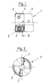
- Figure 1 shows the head part of a tool according to the invention in side view
- Figure 2 shows the tool of Figure 1 in front view
- 3 shows the schematic diagram of an indexable insert seat according to the invention in section BB according to FIG. 1
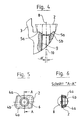
- Figure 4 shows the enlarged section of an insert seat of the tool according to Figures 1 and 2 partially cut
- 5 shows an enlarged indexable insert of the tool according to the invention according to FIGS. 1 and 2
- 6 shows the indexable insert according to FIG. 5 in section AA
Das erfindungsgemäße spanabhebende Werkzeug für die Hochgeschwindigkeitsbearbeitung besteht aus einem schaftförmigen Grundkörper -1- sowie zwei Mittelloch-Wendeschneidplatten -2-, die in Ausnehmungen des Grundkörpers -1- durch Schrauben -7- befestigt sind.The cutting tool according to the invention for high-speed machining consists of a shaft-shaped base body -1- and two center-hole indexable inserts -2- which are fastened in recesses in the base body -1- by screws -7-.
Die Anlagefläche -4- der Wendeschneidplatten -2- besteht aus einem konvexen Zentralbereich - 4b-, der als Teil der Mantelfläche eines Kreiszylinders ausgebildet ist sowie aus zwei seitlichen ebenen Randbereichen -4a-, die senkrecht zur Symmetrieachse -S4- des konvexen Zentralbereiches -4b- angeordnet sind. Die entsprechende Anlagefläche -5- des Werkzeuggrundkörpers -3- besteht aus einem konkaven Zentralbereich -5b-, der ebenfalls als Teil der Mantelfläche eines Kreiszylinders ausgebildet ist und aus zwei seitlichen, ebenen Randbereichen -5a-, die senkrecht zur Symmetrieachse -S5- des konkaven Zentralbereiches -5b-angeordnet sind. Der Radius des konkaven Zentralbereiches -5b- dieser Anlagefläche -5- ist geringfügig kleiner als der Radius des konvexen Zentralbereiches -4b- der Anlagefläche -4- der Wendeschneidplatten -2-. Dadurch wird erreicht, daß der konvexe Zentralbereich -4b- der Anlagefläche -4- jeder Wendeschneidplatte -2-definiert an zwei punktförmigen bzw. kleinflächigen Stellen am unmittelbaren Übergang des konkaven Zentralbereiches -5b- zu den seitlichen ebenen Randbereichen -5a- des Werkzeuggrundkörpers -3- anliegt. Bei einem seitlichen Verkippen der Wendeschneidplatte -2- liegt auch noch ein ebener Randbereich -4a- der Kontaktfläche -4- der Wendeschneidplatte -2- am entsprechenden ebenen Randbereich -5a- der Anlagefläche -5- des Werkzeuggrundkörpers -3- an. Wichtig dabei ist, daß das Verkippen der Wendeschneidplatte -2- derart erfolgt, daß der am Werkzeug näher am Umfang liegende ebene Randbereiche -4a- zur Anlage am ebenen Randbereich -5a- der Anlagefläche -5- des Werkzeuggrundkörpers -3- kommt. Um den Kippeffekt in dieser Richtung zu unterstützen ist die Gewindebohrung -9- im Werkzeuggrundkörper -3- zur Befestigung der Mittelloch-Wendeschneidplatte -2- mit einer Schraube -7- derart eingearbeitet, daß die Längsachse -10- der Gewindebohrung -9- zur Längsachse -8- des Mittelloches der Wendeschneidplatte -2- unter einem spitzen Winkel vom Umfang des Werkzeuges nach innen geneigt verläuft. Wird die Wendeschneidplatte -2- durch die Schraube -7- am Werkzeuggrundkörper -3- befestigt, ergibt sich eine definierte sichere 3-Punkt-Anlage, die auch während des Zerspanungsvorganges erhalten bleibt.The contact surface -4- of the indexable inserts -2- consists of a convex central area - 4b-, which is formed as part of the circumferential surface of a circular cylinder, and of two lateral flat edge areas -4a-, which are arranged perpendicular to the axis of symmetry -S4- of the convex central area -4b-. The corresponding contact surface -5- of the main tool body -3- consists of a concave central area -5b-, which is also formed as part of the circumferential surface of a circular cylinder and of two lateral, flat edge areas -5a- which are perpendicular to the axis of symmetry -S5- of the concave Central area are arranged -5b. The radius of the concave central area -5b- of this contact surface -5- is slightly smaller than the radius of the convex central area -4b- of the contact surface -4- of the indexable inserts -2-. It is thereby achieved that the convex central region -4b- of the contact surface -4- of each indexable insert -2-defines at two punctiform or small-area locations at the direct transition from the concave central region -5b- to the lateral flat edge regions -5a- of the tool base body -3 - is present. If the indexable insert -2- is tilted to the side, there is also a flat edge region -4a- of the contact surface -4- of the indexable insert -2- on the corresponding flat edge region -5a- of the contact surface -5- of the tool base body -3-. It is important here that the indexable insert -2- is tilted in such a way that the flat edge regions -4a lying closer to the circumference of the tool come to rest on the flat edge region -5a- of the contact surface -5- of the tool base body -3-. To support the tilting effect in this direction, the threaded hole -9- in the tool base -3- for fastening the center hole insert -2- is incorporated with a screw -7- in such a way that the longitudinal axis -10- of the threaded hole -9- to the longitudinal axis -8- of the center hole of the insert -2- is inclined inwards at an acute angle from the circumference of the tool. If the indexable insert -2- is fastened to the tool base body -3- by means of the screw -7-, a defined, safe 3-point system is obtained which is also retained during the machining process.
Claims (7)
dadurch gekennzeichnet,
daß im Schnitt (B-B) gesehen, Werkzeuggrundkörper (3) und Schneideinsatz (2) in drei Anlagepunkten auf beiden Anlageflächen (4;5) Kontakt miteinander haben, wobei zwei Anlagepunkte innerhalb der Zentralbereiche (4b;5b) liegen und der dritte Anlagepunkt innerhalb der ebenen Randbereiche (4a;5a) liegt und daß der konvexe Zentralbereich (4b) der Anlagefläche (4) zumindest im Bereich der zwei Anlagepunkte der Abschnitt der Mantelfläche eines Kreiszylinders ist, der sich zumindest annähernd in Richtung der Rotationsachse über den gesamten Zentralbereich (4b) erstreckt.1. Rotating, cutting tool (1) for high-speed machining with one or more interchangeable cutting inserts (2) fastened to a tool base body (3) or a tool cassette and with contact surfaces (4;) on the tool base body (3) and on the cutting insert (2). 5) with a convex or concave central region (4b; 5b) and at least on one side flat edge regions (4a; 5a) for absorbing the centrifugal forces occurring on the cutting inserts (2) through the tool base body (3),
characterized,
that seen in section (BB), tool body (3) and cutting insert (2) in three contact points on both contact surfaces (4; 5) have contact with each other, two contact points lying within the central areas (4b; 5b) and the third contact point within the flat edge areas (4a; 5a) and that the convex central area (4b) of the contact surface (4), at least in the area of the two contact points, is the section of the circumferential surface of a circular cylinder which extends at least approximately in the direction of the axis of rotation over the entire central area (4b) extends.
Applications Claiming Priority (2)
| Application Number | Priority Date | Filing Date | Title |
|---|---|---|---|
| AT0158990A AT397219B (en) | 1990-07-30 | 1990-07-30 | ROTATING CHIP-TOOLING |
| AT1589/90 | 1990-07-30 |
Publications (3)
| Publication Number | Publication Date |
|---|---|
| EP0469672A2 true EP0469672A2 (en) | 1992-02-05 |
| EP0469672A3 EP0469672A3 (en) | 1992-03-25 |
| EP0469672B1 EP0469672B1 (en) | 1994-03-02 |
Family
ID=3516697
Family Applications (1)
| Application Number | Title | Priority Date | Filing Date |
|---|---|---|---|
| EP91201928A Expired - Lifetime EP0469672B1 (en) | 1990-07-30 | 1991-07-23 | Rotating cutting tool |
Country Status (5)
| Country | Link |
|---|---|
| EP (1) | EP0469672B1 (en) |
| JP (1) | JP3369197B2 (en) |
| AT (1) | AT397219B (en) |
| DE (1) | DE59101076D1 (en) |
| ES (1) | ES2051069T3 (en) |
Cited By (6)
| Publication number | Priority date | Publication date | Assignee | Title |
|---|---|---|---|---|
| US6203251B1 (en) * | 1998-10-17 | 2001-03-20 | Wilhelm Fette Gmbh | Indexable milling insert |
| US6413021B1 (en) * | 1999-09-09 | 2002-07-02 | Plansee Tizit Aktiengesellschaft | Rotating cutting tool |
| US7281885B2 (en) | 2004-02-16 | 2007-10-16 | Ceratizit Austria Gesellschaft M.B.H | High-speed milling cutter |
| EP2979797A1 (en) * | 2014-07-28 | 2016-02-03 | Hsin-Tien Chang | Blade positioning structure of disposable milling cutter |
| EP3144087A1 (en) * | 2015-09-18 | 2017-03-22 | Sandvik Intellectual Property AB | A cutting tool, a tool body and a method for producing a tool body |
| EP3311946A4 (en) * | 2015-06-19 | 2019-01-09 | Tungaloy Corporation | Tool body and cutting tool |
Citations (2)
| Publication number | Priority date | Publication date | Assignee | Title |
|---|---|---|---|---|
| EP0039539B1 (en) * | 1980-05-07 | 1984-07-25 | General Electric Company | Floating wedge for use in conjunction with an indexable cutting tool |
| EP0350938A1 (en) * | 1988-07-14 | 1990-01-17 | CERASIV GmbH INNOVATIVES KERAMIK-ENGINEERING | Tool holder for round inserts |
Family Cites Families (3)
| Publication number | Priority date | Publication date | Assignee | Title |
|---|---|---|---|---|
| US3762005A (en) * | 1970-08-28 | 1973-10-02 | Ingersoll Milling Machine Co | Indexable cutting insert |
| CH578908A5 (en) * | 1973-06-29 | 1976-08-31 | Walter Gmbh Montanwerke | |
| DE3321184C2 (en) * | 1983-06-11 | 1985-11-07 | Hartmetall-Werkzeugfabrik Paul Horn GmbH, 7400 Tübingen | Turning tool with a holder for a replaceable cutting insert |
-
1990
- 1990-07-30 AT AT0158990A patent/AT397219B/en not_active IP Right Cessation
-
1991
- 1991-07-23 EP EP91201928A patent/EP0469672B1/en not_active Expired - Lifetime
- 1991-07-23 DE DE91201928T patent/DE59101076D1/en not_active Expired - Lifetime
- 1991-07-23 ES ES91201928T patent/ES2051069T3/en not_active Expired - Lifetime
- 1991-07-24 JP JP20845691A patent/JP3369197B2/en not_active Expired - Lifetime
Patent Citations (2)
| Publication number | Priority date | Publication date | Assignee | Title |
|---|---|---|---|---|
| EP0039539B1 (en) * | 1980-05-07 | 1984-07-25 | General Electric Company | Floating wedge for use in conjunction with an indexable cutting tool |
| EP0350938A1 (en) * | 1988-07-14 | 1990-01-17 | CERASIV GmbH INNOVATIVES KERAMIK-ENGINEERING | Tool holder for round inserts |
Cited By (9)
| Publication number | Priority date | Publication date | Assignee | Title |
|---|---|---|---|---|
| US6203251B1 (en) * | 1998-10-17 | 2001-03-20 | Wilhelm Fette Gmbh | Indexable milling insert |
| US6413021B1 (en) * | 1999-09-09 | 2002-07-02 | Plansee Tizit Aktiengesellschaft | Rotating cutting tool |
| US7281885B2 (en) | 2004-02-16 | 2007-10-16 | Ceratizit Austria Gesellschaft M.B.H | High-speed milling cutter |
| EP2979797A1 (en) * | 2014-07-28 | 2016-02-03 | Hsin-Tien Chang | Blade positioning structure of disposable milling cutter |
| EP3311946A4 (en) * | 2015-06-19 | 2019-01-09 | Tungaloy Corporation | Tool body and cutting tool |
| EP3144087A1 (en) * | 2015-09-18 | 2017-03-22 | Sandvik Intellectual Property AB | A cutting tool, a tool body and a method for producing a tool body |
| WO2017045911A1 (en) * | 2015-09-18 | 2017-03-23 | Sandvik Intellectual Property Ab | A cutting tool, a tool body and a method for producing a tool body |
| CN107921556A (en) * | 2015-09-18 | 2018-04-17 | 山特维克知识产权股份有限公司 | Cutting tool, cutter body and the method for producing cutter body |
| CN107921556B (en) * | 2015-09-18 | 2020-03-13 | 山特维克知识产权股份有限公司 | Cutting tool, tool body and method for producing a tool body |
Also Published As
| Publication number | Publication date |
|---|---|
| ES2051069T3 (en) | 1994-06-01 |
| JP3369197B2 (en) | 2003-01-20 |
| DE59101076D1 (en) | 1994-04-07 |
| AT397219B (en) | 1994-02-25 |
| EP0469672B1 (en) | 1994-03-02 |
| ATA158990A (en) | 1993-07-15 |
| EP0469672A3 (en) | 1992-03-25 |
| JPH04226810A (en) | 1992-08-17 |
Similar Documents
| Publication | Publication Date | Title |
|---|---|---|
| DE60216489T2 (en) | CUTTING TOOL | |
| EP0995528B1 (en) | Milling cutter with indexable cutting inserts | |
| EP1213081B2 (en) | Material-removing precision machining tool | |
| DE3247138C2 (en) | Ball track milling cutter | |
| EP1044081B1 (en) | Milling head with one to three-dimensional adjustable cutting insert and with a positive fitting cutting insert | |
| EP1083017B1 (en) | Rotary cutting tool | |
| WO1999012685A1 (en) | Cutting tip for cutting out profiles | |
| DE3432050A1 (en) | EXTRACTION TOOL WITH A TWO CUTTER HEAD | |
| EP1641585A1 (en) | Cutting insert | |
| DE60018234T2 (en) | Cutting insert and cutting tool | |
| DD292155A5 (en) | REAMER | |
| EP0469672B1 (en) | Rotating cutting tool | |
| DE10305854A1 (en) | Square cutting insert for milling cutters with a negative radial angle of the cutting edges for three-dimensional milling from solid | |
| EP0264642A1 (en) | Cutting tool for metal cutting in particular grooving tool | |
| DE3533125A1 (en) | Milling cutter for high-speed milling | |
| DE10333621B4 (en) | cutting insert | |
| AT401745B (en) | CUTTING INSERT FOR THE RADIAL INSTALLATION IN TOOLS WITH CONCAVE CUTTERS | |
| EP0113097A2 (en) | Adjustable machine reamer | |
| DE2323952B2 (en) | Milling cutter head for face milling | |
| EP1240962B1 (en) | Tool for chip removal on workpieces | |
| DE2633479B2 (en) | Master blade for a diamond circular saw blade | |
| EP0269894B1 (en) | Milling device for machining in particulier for trimming the edges sheet metal bands and plates or similar workpieces | |
| DE19600924C1 (en) | Milling head with cutting plates | |
| EP1027186A2 (en) | Tool for fine machining boring surfaces | |
| EP0938941B1 (en) | Chip cutting tool |
Legal Events
| Date | Code | Title | Description |
|---|---|---|---|
| PUAI | Public reference made under article 153(3) epc to a published international application that has entered the european phase |
Free format text: ORIGINAL CODE: 0009012 |
|
| PUAL | Search report despatched |
Free format text: ORIGINAL CODE: 0009013 |
|
| AK | Designated contracting states |
Kind code of ref document: A2 Designated state(s): DE ES FR GB IT SE |
|
| AK | Designated contracting states |
Kind code of ref document: A3 Designated state(s): DE ES FR GB IT SE |
|
| 17P | Request for examination filed |
Effective date: 19920210 |
|
| 17Q | First examination report despatched |
Effective date: 19930721 |
|
| GRAA | (expected) grant |
Free format text: ORIGINAL CODE: 0009210 |
|
| AK | Designated contracting states |
Kind code of ref document: B1 Designated state(s): DE ES FR GB IT SE |
|
| GBT | Gb: translation of ep patent filed (gb section 77(6)(a)/1977) |
Effective date: 19940228 |
|
| REF | Corresponds to: |
Ref document number: 59101076 Country of ref document: DE Date of ref document: 19940407 |
|
| ITF | It: translation for a ep patent filed |
Owner name: ING. ZINI MARANESI & C. S.R.L. |
|
| REG | Reference to a national code |
Ref country code: ES Ref legal event code: FG2A Ref document number: 2051069 Country of ref document: ES Kind code of ref document: T3 |
|
| ET | Fr: translation filed | ||
| PLBE | No opposition filed within time limit |
Free format text: ORIGINAL CODE: 0009261 |
|
| STAA | Information on the status of an ep patent application or granted ep patent |
Free format text: STATUS: NO OPPOSITION FILED WITHIN TIME LIMIT |
|
| EAL | Se: european patent in force in sweden |
Ref document number: 91201928.8 |
|
| 26N | No opposition filed | ||
| REG | Reference to a national code |
Ref country code: GB Ref legal event code: IF02 |
|
| PGFP | Annual fee paid to national office [announced via postgrant information from national office to epo] |
Ref country code: ES Payment date: 20100726 Year of fee payment: 20 |
|
| PGFP | Annual fee paid to national office [announced via postgrant information from national office to epo] |
Ref country code: SE Payment date: 20100715 Year of fee payment: 20 Ref country code: IT Payment date: 20100726 Year of fee payment: 20 Ref country code: DE Payment date: 20100723 Year of fee payment: 20 Ref country code: FR Payment date: 20100805 Year of fee payment: 20 |
|
| PGFP | Annual fee paid to national office [announced via postgrant information from national office to epo] |
Ref country code: GB Payment date: 20100722 Year of fee payment: 20 |
|
| REG | Reference to a national code |
Ref country code: DE Ref legal event code: R071 Ref document number: 59101076 Country of ref document: DE |
|
| REG | Reference to a national code |
Ref country code: DE Ref legal event code: R071 Ref document number: 59101076 Country of ref document: DE |
|
| REG | Reference to a national code |
Ref country code: GB Ref legal event code: PE20 Expiry date: 20110722 |
|
| REG | Reference to a national code |
Ref country code: SE Ref legal event code: EUG |
|
| PG25 | Lapsed in a contracting state [announced via postgrant information from national office to epo] |
Ref country code: GB Free format text: LAPSE BECAUSE OF EXPIRATION OF PROTECTION Effective date: 20110722 |
|
| PG25 | Lapsed in a contracting state [announced via postgrant information from national office to epo] |
Ref country code: DE Free format text: LAPSE BECAUSE OF EXPIRATION OF PROTECTION Effective date: 20110724 |
|
| REG | Reference to a national code |
Ref country code: ES Ref legal event code: FD2A Effective date: 20140826 |
|
| PG25 | Lapsed in a contracting state [announced via postgrant information from national office to epo] |
Ref country code: ES Free format text: LAPSE BECAUSE OF EXPIRATION OF PROTECTION Effective date: 20110724 |