EP0469643B1 - Disk player - Google Patents
Disk player Download PDFInfo
- Publication number
- EP0469643B1 EP0469643B1 EP91118183A EP91118183A EP0469643B1 EP 0469643 B1 EP0469643 B1 EP 0469643B1 EP 91118183 A EP91118183 A EP 91118183A EP 91118183 A EP91118183 A EP 91118183A EP 0469643 B1 EP0469643 B1 EP 0469643B1
- Authority
- EP
- European Patent Office
- Prior art keywords
- disk
- moving
- tray
- lever
- turntable
- Prior art date
- Legal status (The legal status is an assumption and is not a legal conclusion. Google has not performed a legal analysis and makes no representation as to the accuracy of the status listed.)
- Expired - Lifetime
Links
Images


Classifications
-
- G—PHYSICS
- G11—INFORMATION STORAGE
- G11B—INFORMATION STORAGE BASED ON RELATIVE MOVEMENT BETWEEN RECORD CARRIER AND TRANSDUCER
- G11B17/00—Guiding record carriers not specifically of filamentary or web form, or of supports therefor
- G11B17/02—Details
- G11B17/04—Feeding or guiding single record carrier to or from transducer unit
- G11B17/05—Feeding or guiding single record carrier to or from transducer unit specially adapted for discs not contained within cartridges
- G11B17/053—Indirect insertion, i.e. with external loading means
- G11B17/056—Indirect insertion, i.e. with external loading means with sliding loading means
-
- G—PHYSICS
- G11—INFORMATION STORAGE
- G11B—INFORMATION STORAGE BASED ON RELATIVE MOVEMENT BETWEEN RECORD CARRIER AND TRANSDUCER
- G11B17/00—Guiding record carriers not specifically of filamentary or web form, or of supports therefor
- G11B17/02—Details
- G11B17/022—Positioning or locking of single discs
- G11B17/028—Positioning or locking of single discs of discs rotating during transducing operation
- G11B17/0284—Positioning or locking of single discs of discs rotating during transducing operation by clampers
- G11B17/0286—Positioning or locking of single discs of discs rotating during transducing operation by clampers mounted on a pivotal lever
-
- G—PHYSICS
- G11—INFORMATION STORAGE
- G11B—INFORMATION STORAGE BASED ON RELATIVE MOVEMENT BETWEEN RECORD CARRIER AND TRANSDUCER
- G11B17/00—Guiding record carriers not specifically of filamentary or web form, or of supports therefor
- G11B17/02—Details
- G11B17/022—Positioning or locking of single discs
- G11B17/028—Positioning or locking of single discs of discs rotating during transducing operation
- G11B17/0288—Positioning or locking of single discs of discs rotating during transducing operation by means for moving the turntable or the clamper towards the disk
-
- G—PHYSICS
- G11—INFORMATION STORAGE
- G11B—INFORMATION STORAGE BASED ON RELATIVE MOVEMENT BETWEEN RECORD CARRIER AND TRANSDUCER
- G11B17/00—Guiding record carriers not specifically of filamentary or web form, or of supports therefor
- G11B17/22—Guiding record carriers not specifically of filamentary or web form, or of supports therefor from random access magazine of disc records
- G11B17/30—Guiding record carriers not specifically of filamentary or web form, or of supports therefor from random access magazine of disc records wherein the playing unit is moved according to the location of the selected record
Definitions
- the present invention relates to a disk player, particularly to a disk player of the automatic loading type.
- the present invention also relates to a multidisk player.
- a disk put on the turntable of a conventional disk player of the automatic loading type in which a disk conveyance mechanism for automatically conveying the disk to a play position on the turntable is provided to eliminate the manual operation of loading the disk on the turntable, is automatically clamped thereon by a clamp mechanism shown in FIG. 31.
- the clamp mechanism comprises a disk-shaped pusher 152, which acts to clamp the disk in cooperation with the turntable 151 which rotates while bearing the disk 150 to be played, and a support 154, which is borne in a swingable manner within a prescribed range by a support shaft 153 extending in parallel with the main surface of the turntable 151 and bears the pusher 152 rotatably by the free end of the support.
- a helical spring (not shown in the drawing), which urges the support 154 in such a direction as to move the free end thereof toward the turntable 151, or the like is used to apply a pushing force to the disk 150.
- the stroke H of the swing of the support 154 which is necessary to prevent the pusher 152 and the disk 150 from coming into contact with each other when the disk is released from the clamp mechanism, is large, it makes a problem that it is very difficult to reduce the size of the disk player.
- a multidisk player is able to contain a plurality of disks, to successively select any one of the disks contained and to continuously replay them.
- the conventional multidisk player has an extremely large body, and the total cost of the multidisk player is high.
- the present invention is made in order to solve the above-mentioned problems and other problems.
- a multidisk player of the present invention comprises a player housing, playing means for playing the disk, the playing means having a turntable for mounting a disk thereon and being placed inside of the player housing, disk holding means for holding a plurality of disks, the disk holding means capable of being inserted into the player housing to be loaded at a loading portion inside of the player housing, the disk holding means comprising a housing portion and a plurality of tray members for bearing disks, the tray members being provided inside of the housing portion in such a manner that the tray members are disposed in a direction nearly perpendicular to the disc bearing side of the turntable, the tray members being capable of protruding out of the housing portion and disk takeout and conveyance mechanism for taking a disk out of the disk holding means and conveying the disk to a playing position, the disk take out and conveyance mechanism having supporting member extending in a direction of the disposition of the tray members, moving member provided on the supporting member movably in the direction of the disposition of the tray members, protrud
- the disk player is a multiple disk player (or a multidisk player) in which a plurality of disks can be housed and desired ones of the housed disks can be sequentially selected and played.
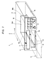
- a reference numeral 1 in FIG. 1 denotes the disk player as a whole.
- the front panel 3 of a player housing 2 has an oblong opening 3a for loading a magazine 5 as a disk holder into the housing.
- the opening 3a extends rightward and leftward direction.
- An arrow Y indicates the forward direction.
- An arrow X indicates the leftward direction.
- An arrow Z indicates the upward direction.
- a display section 7 and operation buttons 6 for operating the disk player are provided on the front panel 3.
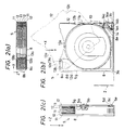
- the magazine 5 comprises a magazine body 8, which is flat and parallelepipedal as a whole and serves as a housing, and a kind of three trays 11 and another kind of three trays 12, the total number of which is six.
- Each of the trays 11 and 12 is shaped as a square plate.
- Disks 10 are borne on the main sides of the trays 11 and 12.
- the trays 11 and 12 (hence the disks 10 as well) are sequentially disposed at prescribed intervals in an upward and a downward directions (the direction of the arrow Z and the opposite thereof) perpendicular to the disk bearing side of a turntable described hereinafter.
- the trays 11 and 12 can be rotated about a rotary support shaft 8a provided at the right rear corner of the magazine body 8 and extending upward and downward (in the direction of disposition of the trays), so that each of the trays can be moved into and out of the magazine body along the plane of the main side of the tray.
- the constitution of the magazine 5 is described in detail from now on.
- the magazine body 8 is provided with seven partitions 8b disposed upward and downward (in the direction of the arrow Z and the opposite thereof).
- the trays 11 and 12 are located between the partitions 8b.
- the partitions 8b have small circular openings 8c coaxial with each other and located near the rotary support shaft 8a.
- FIGS. 4(a), 4(b), 5(a) and 5(b) show the details of the trays 11 and 12.
- the trays are provided with openings 11a and 12a so that the openings 11a and 12a can face the openings 8c of the partitions 8b.
- the openings 8c of the partitions 8b are referred to as the first openings.
- the openings 11a and 12a of the trays 11 and 12 are referred to as the the second openings.
- Five spherical movable members 13a which can be moved along the direction (the direction of the arrow Z and the opposite thereof) of disposition of the partitions 8b, are fitted in the openings 8c, 11a and 12a.
- each of the spherical movable members 13a is equal to the interval of disposition of the trays 11 and 12.
- a pair of plate springs 13b provided at the top and bottom of the magazine body 8 urge the spherical movable members 13a in such directions as to move the members toward each other.
- a push lever 14 is provided at the left front corner of the magazine body 8 and extends nearly forward and backward (in the direction of the arrow Y and the opposite thereof).
- the push lever 14 is attached at the front end thereof to the magazine body 8 by a pin 14a so that the push lever is swingable.
- the pin 14a extends upward and downward (in the direction of the arrow Z and the opposite thereof).
- the rear end of the push lever 14 can be smoothly engaged with the free end of each of the trays 11 and 12.
- a spring member 14b is engaged with the push lever 14 and urges it counterclockwise (as to FIG. 2(b)) to apply a tray pushing force to the lever.
- the push lever 14 is provided with a projection 14c.
- the projection 14c can be brought into contact with the edge portion 3b along the opening 3a of the player housing 2 thereof when the magazine 5 is pulled out of the magazine loading portion in the player housing.
- the projection 14c acts to swing the push lever 14 to urge the trays 11 and 12 toward their housed positions in the magazine body 8.
- the push lever 14 and the spring member 14b constitute a push means for pushing the trays 11 and 12 toward the housed positions and the rotary support shaft 8a in the magazine body 8.
- the push means, the openings 8c (first openings) of the partitions of the magazine body 8, the openings 11a and 12a (second openings) of the trays 11 and 12, the spherical movable members 13a and the plate springs 13b constitute a holding mechanism for holding the trays in the housed positions in the magazine body.
- the trays 11 and 12 have almost the same shape but only differ from each other in the shapes and positions of claws 11b and 12b, on which the listener puts his fingertip when he pulls out the tray from the magazine body 8.
- the free end portions of the trays 11 and 12 have notches 11c and 12c, in which the push lever 14 is engaged.
- the free end portions also have pairs of jig insertion holes 11d, 11e, 12d and 12e.
- Soft members 11f and 12f made of synthetic leather or the like are provided in prescribed positions on the main sides of the trays 11 and 12, which can face the disk bearing sides of the adjacent trays.
- the trays 11 and 12 are provided with arc-shaped recesses 11h, 11i, 12h and 12i along the loci of movement of the soft members 11f and 12f provided on the adjacent trays. Since the recesses 11h, 11i, 12h and 12i are provided, the height of the pileup of the six trays 11 and 12 in all is reduced, namely, the height of the magazine 5 is reduced.
- an engaging claw 5a is provided almost at the central portion of the right side of the magazine 5 and attached at one end thereof to the magazine body 8 by a pin 5b so that the claw can be swung in a prescribed range.
- Another engaging claw 5c is attached at one end thereof to the right front corner of the magazine 5 by a pin 5d so that the claw can be swung in a prescribed range.
- the free end of the engaging claw 5c is urged outward by a helical spring 5e.
- the free ends of the engaging claws 5a and 5c can be engaged with the edge portion 3b along the opening 3a (refer to FIGS. 1 and 2(b)).
- the engaging claws 5a and 5c and the helical spring 5e constitute a loading prevention means for preventing the magazine 5 from being loaded into the loading portion of the player housing 2 when the posture of the magazine is not proper for the loading thereof.
- the engaging claw 5a swings due to the weight thereof and projects outward from the magazine 5 and the free end of the claw is engaged with the edge portion 3b along the opening 3a to prevent the magazine from being loaded.
- the engaging claw 5c protruded outward by the helical spring 5e is engaged with the edge portion 3b of the opening 3a to prevent the magazine 5 from being loaded.
- the loading prevention means is constituted by the engaging claws 5a and 5c and the helical spring 5e which are simple members, the constitution is simple enough to make it easy to reduce the cost of the disk player.
- a circular opening 14e is provided in the projection 14c of the push lever 14 supported in a swingable manner on the magazine 5.
- the housing body 8 of the magazine 5 is provided with an overhang portion 8d extending along the bottom of the push lever 14.
- a pillar-like projection 8e is provided on the overhang 8d.
- a circular recess 8f is provided in the top of the projection 8e.
- a spherical movable member 8g is provided in the recess 8f so that the member 8g can be moved upward and downward (in the direction of the arrow Z and the opposite thereof).
- the push lever 14 and the spherical movable member 8g constitute a protrusion restricting means for restricting the protrusion of the trays 11 and 12 from the magazine body 8 when the magazine 5, which serves as a disk holder, is in the posture of being upside down.
- the spherical movable member 8g moves due to the weight thereof and a part of the member enters into the opening 14e of the push lever 14 to restrict the swing of the push lever to restrain the protrusion of the trays 11 and 12 out of the magazine body 8.
- the protrusion restricting means is constituted by the push lever 14 and the spherical movable member 8g which are members of simple forms, the constitution is simple enough to make it easy to reduce the cost of the disk player.
- the spherical movable member 8g may not be manufactured for the disk player in particular but may be one on the market.
- a chassis 16 is mounted as a support member on a bottom plate 15 secured in the housing 2.
- the chassis 16 comprises a horizontal surface portion 16a extending forward and backward (in the direction of the arrow Y and the opposite thereof) and right and leftward (in the direction of the arrow X and the opposite thereof), and a pair of vertical surface portions 16b and 16c continuous to the right and left ends of the horizontal surface portion 16a and extending forward and backward (in the direction of the arrow Y and the opposite thereof) and upward and downward (in the direction of the arrow Z and the opposite thereof or in the direction of disposition of the trays).
- a moving member 18 is provided between the rear ends of the vertical surface portions 16b and 16c of the chassis 16 and attached to the vertical surface portions 16b and 16c so that the moving member can be moved upward and downward (in the direction of disposition of the trays 11 and 12).
- a bearing plate 22 as a holding member is attached to the top of the moving member 18.
- the turntable 23 is mounted on the bearing plate 22.
- a carriage 24 bearing an optical pickup means is provided on the bearing plate 22 and attached to the bearing plate so that the carriage can be moved along a plane (which contains the disk bearing side 23a (shown in FIG. 10) of the turntable in nearly rightward and leftward directions (in the direction of the arrow X and the opposite thereof).
- the turntable 23 is directly rotated by a spindle motor 25 shown in FIGS. 8 and 10.
- a carriage drive means for driving the carriage 24 is provided on the bearing plate 22.
- the turntable 23, the spindle motor 25, the carriage 24 including the optical pickup means and the carriage drive means constitute a playing means for playing the disk.
- the playing means is borne on the moving member 18 so that the playing means is moved together with the moving member upward and downward (in the direction of the arrow Z and the opposite thereof).
- the turntable 23 is provided with a magnet 23b.
- the pusher 80 of the clamping mechanism has a member 84e made of magnetic material at its yoke portion. Therefore, a clamping force to the disk-shaped pusher of the clamp mechanism is produced by the magnet force of the magnet 23b.
- the bearing plate 22 for holding the spindle motor 25 and the turntable 23 is made of a magnetic material and emplaced to face the side of the turntable 23 opposite to the disk bearing side thereof so that the turntable is attracted toward the bearing plate 22 by the magnetic force of the magnet 23b. For that reason, the output shaft 25a of the spindle motor 25 and a bearing portion (not shown in the drawings) of the spindle motor for supporting the output shaft are put into tight contact with each other.
- a moving lever 33 made of a steel plate is attached to the bottom of the chassis 16 so that the lever can be moved forward and backward (in the directions of loading and unloading of the magazine, which are the direction of the arrow Y and the opposite thereof).
- FIGS. 13(a) and 13(b) show the details of the moving lever 33.
- the rear end portion of the moving lever 33 is provided with a projection 33a extending downward so that the rear of the magazine 5 can be engaged with the projection 33a.
- the moving lever 33 is moved backward.
- the lever 33 is coupled with a helical spring (not shown in the drawings) for applying a forward (in the direction of the arrow Y) biasing force to the lever.
- a pair of detection switches 34 and 35 are provided at the left side of the moving lever 33 so that the projections 33b and 33c of the moving lever 33 can be engaged with the operating elements of the switches to put the elements into action.
- the moving lever 33 and the detection switches 34 and 35 constitute a magazine loading detection means for detecting that the magazine 5 is loaded in the magazine loading portion of the player housing 2.
- a moving means for moving the moving member 18 upward and downward (the direction of the arrow Z and the opposite thereof) is described from now on.
- a pair of moving plates 37 and 38 are provided at the outsides of the right and left vertical surface portions 16b and 16c of the chassis 16 so that the moving plates extend forward and backward.
- FIGS. 14 and 15 show the details of the moving plates 37 and 38.
- the moving plates 37 and 38 are provided with guide grooves 37a, 37b, 38a, 38b and 38c extending in the longitudinal directions of the moving plates.
- the moving plates 37 and 38 are movably fitted at the guide grooves 37a, 37b, 38a, 38b and 38c on pins 16d projecting from the outsides of the vertical surface portions 16b and 16c, so that the moving plates are attached to the chassis 16 which serves as a support member.
- the moving plates 37 and 38 can be reciprocated forward and backward.
- two pins 18a and other two pins 18a project from the left and right sides of the moving member 18, respectively.
- the pins 18a are movably fitted in four guide grooves 16e extending upward and downward in the left and right vertical surface portions 16b and 16c of the chassis 16 which serves as a support member. As a result, the moving member 18 is guided upward and downward.
- the pins 18a provided on the right and left sides of the moving member 18 project out of the chassis 16 through the guide grooves 16e thereof.
- the moving plates 37 and 38 are movably engaged with the pins 18a in steplike cam holes 37d and 38d provided in the inside surfaces of the moving plates.
- the cam hole 37d of the moving plate 37 extends obliquely downward (oppositely to the direction of the arrow Z) and forward (in the direction of the arrow Y) as a whole.
- the cam hole 38d of the moving plate 38 extends obliquely upward and forward as a whole.
- the cam holes 37d and 38d are so provided that the moving member 18 is moved vertically when the moving plates 37 and 38 are moved relative to each other.
- a rack 37h is provided at the front end of the left moving plate 37 so that the rack extends in the direction of extension of the moving plate 37.
- the small gear 40a of a double gear 40 provided on the chassis 16 is engaged with the rack 37h.
- the moving plate 37 is driven by a motor 45 through a speed reduction gear mechanism 41 including the double gear 40.
- a turning lever 47 is provided between the left and right moving plates 37 and 38 and attached to the chassis 16 by a pair of pins 16g projecting from the chassis, so that the lever can be turned about a virtual center 47a.
- the lever 47 is pivotally coupled at both ends thereof to the left and right moving plates 37 and 38.
- the motor 45, the speed reduction gear mechanism 41, the turning lever 47 and ambient small members related to them constitute a driving force application means for applying driving forces to the moving plates 37 and 38.
- the driving force application means and the moving plates 37 and 38 constitute a moving means for moving the moving member 18 upward and downward (in the direction of the arrow Z and the opposite thereof).
- a detection switch 49 is provided on the upper part of the left vertical surface portion 16b of the chassis 16 to detect that the moving plate 37, which is reciprocated forward and backward, is in the most forwardly moved position (forward movement limit position) thereof.
- the detection switch 49 is put into action when a part of the moving plate 37 is engaged with the operating portion of the switch.
- An address plate 50 having six slits 50a disposed in the direction of movement of the moving plate 37 is provided at the right of the front end of the moving plate.
- a photosensor 51 for detecting the slits 50a of the address plate 50 is provided behind the detection switch 49.
- the detection switch 49 is herein referred to as the first sensor, while the photosensor 51 is herein referred to as the second sensor.
- a slit detection signal obtained from the second sensor is sent to a counter (not shown in the drawings) which counts the number of the slit detection signals.
- a controller (not shown in the drawings) for automatically controlling the disk player is provided in a prescribed position inside the player housing 2. The controller finds out the stopped position of the moving plate 37 in terms of the count of the counter.
- the detection switch 49 which is the first sensor, the address plate 50, the photosensor 51, which is the second sensor, the counter and the controller constitute a positioning mechanism for moving the moving plate 37 to a desired address position and setting the plate in that position.
- the positioning mechanism acts to move the moving plate 37 through a distance corresponding to the difference between a present address and a desired address.
- the positioning mechanism acts to move the moving plate 37 backward until the detection switch 49 generates a detection signal, and the positioning mechanism thereafter acts to move the moving plate 37 to a position of desired address.
- a tray protruder 53 which is engaged with one of the trays 11 and 12 (refer to FIG. 2(b) etc.) in the magazine 5 to protrude the tray out of the magazine body 8, is provided at the right front corner of the moving member 18.
- the tray protruder 53 is shaped nearly as L-shape as a whole.
- a pin 53a projecting from the tray protruder 53 is slidably engaged in the arc-shaped guide groove 18d of the moving member 18 so as to guide the tray protruder 53.
- the tray protruder 53 is turned about the center of curvature of the arc-shaped guide groove 18d to push the tray by the turned end 53b of the tray protruder to protrude the tray out of the magazine body.
- the vertual axis (the center of curvature of the arc-shaped guide groove 18d) of turning of the tray protruder 53 and the position of the rotary support shaft 8a for the trays 11 and 12 are coincident with each other.
- the tray protruder 53 pushes the tray 11 or 12 at the portion 11k or 12k (refer to FIGS. 4(a) and 5(a)) thereof near the rotary support shaft 8a so that the tray is protruded out of the magazine body 8.
- the above-described moving means comprising the moving plates 37 and 38 and so forth to move the moving member 18, and the positioning mechanism comprising the address plate 50 and so forth constitute a tray protruder moving means for moving the tray protruder 53 together with the moving member 18 to put the tray protruder in such a position as to engage the tray protruder with the tray 11 or 12 bearing the disk 10 to be played.
- a tray protruder drive means for turning the tray protruder 53 to protrude the tray 11 or 12 out of the magazine body 8 is described from now on.
- a moving member 56 is provided at the right side on the under surface of the chassis 16 and extends forward and backward.
- the moving member 56 is attached to the chassis 16 so that the moving member 56 can be moved in the direction of extension thereof.
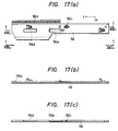
- FIGS. 17(a), 17(b) and 17(c) show the details of the moving member 56.
- a rack 56a is provided at the right front corner of the moving member 56 and extends in the direction of extension of the moving member.
- the small gear 57a of a double gear 57 provided on the chassis 16 is engaged with the rack 56a.
- the moving member 56 is driven by a motor 62 through a speed reduction gear mechanism 58 including the double gear 57.
- the speed reduction gear mechanism 58 and the motor 62 constitute a driving force application means for applying a driving force to the moving member 56.
- a swing lever 63 is provided near the bottom of the magazine loading portion of the player housing 2 and extends nearly rightward and leftward so that the magazine 5 loaded in the magazine loading portion is protruded out of the portion by the swing lever.
- the swing lever 63 is attached nearly at the central portion thereof by a pin 63a to an auxiliary chassis 64 provided at the bottom of the chassis 16, so that the lever 63 is swingable.
- the pin 63a extends upward and downward (in the direction of the arrow Z and the opposite thereof).
- a projection 63b is provided at the right end of the swing lever 63 and extends upward. The projection 63b of the swing lever 63 is brought into contact with the rear of the magazine 5.
- a gear 63c the center of curvature of which is on the pin 63a, is provided at the left end of the swing lever 63 and engaged with the brake gear 65a (shown in FIG. 12) of a damper 65, which applies a braking force by the viscous resistance of a viscous substance such as grease held in the damper.
- a helical spring 63d applies a magazine protruding force to the swing lever 63.
- the swing lever 63, the damper 65 and the helical spring 63d constitute a protrusion means for protruding the magazine 5 out of the magazine loading portion of the player housing 2.
- a locking member 67 (not shown in the drawings) is rotatably provided near the moving member 56 so that the turning end of the locking member is engaged in the engaging recess 5g (refer to FIGS. 2(b) and 2(c)) of the magazine 5 to lock the magazine in the loaded position thereof in the player housing 2.
- the moving member 56 is moved forward, the magazine 5 is unlocked from the locking member 67.
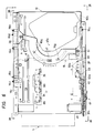
- a first lever 71 and a second lever 72 are provided at the right end of the chassis 16 and extend forward and backward (in the direction of the arrow Y and the opposite thereof).
- the levers 71 and 72 are attached to the chassis 16 so that the levers can be reciprocated in the directions of extension thereof.
- FIGS. 19 and 20 show the details of the first and the second levers 71 and 72.
- the first lever 71 is for driving the supports of a clamp mechanism described hereinafter.
- the second lever 72 is for turning the tray protruder 53 (refer to FIG. 9) through an intermediate lever 73 shown in FIGS. 11 and 16.
- the intermediate lever 73 is rotatably supported on the chassis 16 by a pin 73a extending upward and downward.
- a pin 72a projecting from the second lever 72 is engaged in a cam groove 73b (shown in FIG. 11) provided at the turning end of the intermediate lever 73, so that the lever 73 is turned.
- a rod 73c extending downward is provided at the other turning end of the intermediate lever 73 and fitted in the hole 53d of the tray protruder 53 (shown in FIG. 9) to turn the tray protruder.
- the first and the second levers 71 and 72 are moved by the moving member 56.
- a first recess 56c is provided in a prescribed position in the moving member 56.
- the first lever 71 is provided with a first opening 71c which can face the first recess 56c.
- a movable member 74 which can be engaged in the first recess 56c, is provided in the first opening 71c.
- the first recess 56c, the first opening 71c, the movable member 74 and so forth constitute a locking/unlocking means for appropriately locking or unlocking the first lever 71 to or from the moving member 56 depending on the movement thereof.
- the first lever 71 is moved or stopped together with the moving member 56 depending on the distance of the movement thereof, to drive the clamp mechanism described hereinafter.
- the locking/unlocking means is described in detail in the United States Patent 4,631,716.
- the moving member 56 is provided with a second and a third recesses 56d and 56e.
- the second lever 72 is provided with a second and a third openings 72d and 72e which can face the second and the third recesses 56d and 56e.
- the movable member 75 is provided between the second recess 56d and the second opening 72d.
- the movable member 76 is provided between the third recess 56e and the third opening 72e.
- the second and the third recesses 56d and 56e, the second and the third openings 72d and 72e, the movable members 75 and 76 and so forth constitute a locking/unlocking means for appropriately locking or unlocking the second lever 72 to or from the moving member 56 depending on the movement thereof.
- the second lever 72 is moved or stopped together with the moving member 56 depending on the distance of the movement thereof, to drive the tray protruder 53 (refer to FIG. 9).
- the locking/unlocking means, the second lever 72, the moving member 56 and the driving force application means including the motor 62 and so forth to apply the driving force to the moving member 56 constitute a tray protruder drive means for turning the tray protruder 53 (shown in FIG. 9) to protrude the tray 11 or 12 (refer to FIGS. 4 and 5) out of the magazine body 8.
- the tray protruder drive means the chassis being a support member, the moving member 18, the tray protruder 53 and the tray protruder moving means including the moving plates 37 and 38 and so forth constitute a tray protrusion means for protruding the tray 11 or 12 out of the magazine body 8 as the tray remains bearing the disk 10 to be played.
- a pair of plate-shaped supports 78 and 79 are provided on the moving member 18 and extending forward and backward (in the direction of the arrow Y and the opposite thereof) and rightward and leftward (in the direction of the arrow X and the opposite thereof).
- the supports 78 and 79 are attached to the moving member 18 by pins 78a and 79a so that the supports are swung in planes nearly perpendicular to the disk bearing side 23a (shown in FIG. 10) of the turntable 23 (refer to FIGS. 8 and 10).
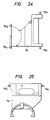
- FIGS. 24 and 25 show the details of the supports 78 and 79.
- a disk-shaped pusher 80 is rotatably attachable to the free ends of the supports 78 and 79 so that the pusher is brought into contact with the side of the disk 10 opposite to the turntable 23 to clamp the disk in cooperation with the turntable.
- the free end of the support 78 is located in contact with the side of a flange 81a opposite to the disk pushing side thereof.
- the flange 81a is provided on the body 81 of the pusher 80.
- the free end of the other support 79 is located in contact with the disk pushing side of the flange 81a.
- the pusher 80 is vertically pinched between the free ends of the supports 78 and 79.
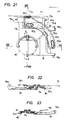
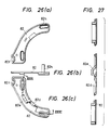
- FIGS. 9 and 21 show the details of the clamp cam 82.
- the nearly central part of the clamp cam 82 is provided with cam portions 82d and 82e, which are engaged with columnar projections 78d and 79d (shown in FIG. 21) provided on the tops of the supports 78 and 79.
- the clamp cam 82 is reciprocated to drive the supports 78 and 79 to tighten and loosen the pusher 80 to and from the turntable 23.
- the cam portions 82d and 82e are so shaped that the supports 78 and 79 are separated from the pusher 80 after the pusher is certainly attracted and tightened to the turntable 23 by a magnet force of the magnet 23b when the disc is to be clamped and that the pusher is separated from the turntable after the pinching of the pusher between the supports is completed when the disc is to be released from its clamped state.
- a U-shaped notch 82f is provided at one end of the clamp cam 82 and smoothly engaged with a projection 71e provided on the first lever 71 (shown in FIGS. 11, 16, 19(a) and 19(b)) and extending downward.
- the first lever 71 is reciprocated to move the clamp cam 82 to swing the supports 78 and 79 upward and downward.
- the clamp cam 82, the first lever 71, the moving member 56 (shown in FIG. 17, etc.), the locking/unlocking means including the movable member 74 and so forth to appropriately lock or unlock the first lever 71 and the moving member 56 to or from each other depending on the movement of the moving member, and the driving force application means including the motor 62 and so forth to apply the driving force to the moving member 56 constitute a drive means for driving the supports 78 and 79.
- the drive means and the supports 78 and 79 constitute a pusher moving means for tightening and loosening the pusher 80 to and from the turntable 23.
- the pusher moving means and the pusher 80 constitute the clamp mechanism for clamping the disk 10.
- springs 78f and 79f are provided to urge the supports 78 and 79 in such directions as to move the pusher 80 toward the disk bearing side 23a (refer to FIG. 10) of the turntable 23.
- a slope or tapered portion 78g is provided at the free end of the support 78 so that the slope is engaged with the peripheral portion (of the body 81) of the pusher 80 to position the pusher in a plane parallel with the disk bearing side 23a of the turntable 23.
- the pusher 80 can thus be accurately aligned to the turntable 23.
- the pusher 80 is provided with a disk centering projection 84, which is fitted in the center hole of the disk 10 to center the disk.
- the turntable 23 is provided with a recess 23c, in which the disk centering projection 84 is fitted when the disk 10 is clamped on the turntable. Because of such constitution, the disk 10 is prevented from deviating in the direction parallel with the disk bearing side 23a of the turntable 23.
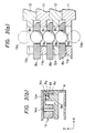
- FIG. 28 shows a view taken along line XXVIII-XXVIII shown in FIG. 10.
- FIG. 29 shows a sectional view along a line XXIX-XXIX shown in FIG. 28.
- the disk centering projection 84 of the pusher is movable in a prescribed range along the axis of gyration of the pusher.
- the disk centering projection 84 is attached to the body 81 of the pusher 80 through a cam means which comprises three cam surfaces 84a provided on the disk centering projection 84 and three spherical guide members 85 provided on the body 81 of the pusher 80 so as to slide in contact with the cam surfaces 84a.
- the disk centering projection 84 is moved along the axis of gyration of the pusher 80, the projection is rotated about the axis.
- a spring 84d is provided as an urging means for urging the disk centering projection 84 to rotate it to project upward (in the direction of the arrow Z) from the body 81 of the pusher 80.
- the three spherical guides 85 are emplaced at equal intervals in the direction of gyration of the pusher 80. As shown in FIGS. 10 and 29, a part of each of the spherical guides 85 project at the disk pushing side of the body 81 of the pusher 80 so that the part is located in contact with the surface of the disk 10. For that reason, the disk 10 is supported at three points by the pusher 80 so that the disk is accurately clamped.
- the above-described clamp mechanism acts as a disk moving means so that the disk 10 borne on the tray 11 or 12 protruded out of the magazine body 8 by the tray protrusion means is moved in an upward direction (the direction of the arrow Z) perpendicular to the disk bearing side 23a (refer to FIG. 10) of the turntable 23.
- the disk moving means and the tray protrusion means constitute a disk takeout and conveyance mechanism for sequentially selecting each of the desired disks 10 in the magazine 5 and conveying the selected disk onto the disk bearing side 23a of the turntable 23.
- FIGS. 30(a), 30(b) and 30(c) show the details of the disk pusher drive cam 87.
- an opening 87c is provided at one end of the disk pusher drive cam 87.
- a pin 82h (refer to FIGS. 26(a) and 26(b)) projecting upward from the end of the clamp cam 82 is smoothly fitted in the opening 87c so that the disk pusher drive cam 87 is moved as the clamp cam 82 is moved.
- the disk pusher drive cam 87 is for driving a disk pusher 88 (shown in FIGS.
- the chassis 16 is provided with two detection switches 89 and 90 along the detection switches 34 and 35.
- the detection switches 89 and 90 are for detecting the moved position of the moving member 56 as the switches are engaged with the moving member driven by the motor 62.
- Detection signals sent from the detection switches 34, 35, 49, 89 and 90 and the photosensor 51 are entered into the above-mentioned controller (not shown in the drawings), which sends out operation signals to operate the motors 45 and 62 and the turntable 23 at prescribed timing described hereinafter.
- the tray (for example, the tray 12) bearing the disk to be played is protruded out of the magazine body 8, as shown in FIG. 2(b), so that the disk is moved to a position in which the disk is coaxial with the disk bearing side 23a (refer to FIG. 10) of the turntable 23 or located immediately under the disk bearing side.
- the moving member 56 is moved backward further oppositely to the direction of the arrow Y, and the second lever 72 is unlocked from the moving member and the first lever 71 is simultaneously locked to the moving member. Therefore, the first lever 71 is moved backward together with the moving member 56 so that the supports 78 and 79 (shown in FIGS. 21 etc.) of the clamp mechanism is swung upward (in the direction of the arrow Z). For that reason, the disk is lifted upward so that it is clamped on the turntable 23. As a result, the disk can be played by operating the turntable 23 and the carriage 24 (refer to FIG. 9).
- the disk After the disk is played, it is housed back in the magazine body 8. Since the operation of housing the disk back in the magazine body 8 is performed by inversely taking the steps of the above-described operation of loading the disk on the turntable 23, the operation of housing the disk back in the magazine body is not described in detail. Such operations are repeated depending on the number of appointed disks or tunes.
- a clamp mechanism for clamping a disk 10 comprises a pusher 80, which acts to clamp the disk in cooperation with a turntable 23, and a pusher moving means for tightening and loosening the pusher to and from the turntable.
- the pusher moving means comprises a pair of supports 78 and 79, which are swingable in planes nearly perpendicular to the disk bearing side 23a of the turntable 23 and whose free ends are brought into contact with the disk pushing side of the pusher and the opposite side thereof to pinch the pusher therebetween, and drive means for driving the supports. Because of such constitution, the pusher 80 keeps parallel with the disk bearing side of the turntable whatever position the pusher takes.
- the stroke of the swing of the supports 78 and 79 which are necessary to prevent the pusher and the disk on the turntable from coming into contact with each other when the disk is released from the clamp mechanism, can be decreased to make it easy to reduce the size of the whole disk player, particularly the height thereof.
- the pushing means 80 when the disc is to be clamped, the pushing means 80 is attracted and tightened to the turntable 23 by a magnet force of the magnet in the turntable 23 before the pair of support members 78 and 79 are separated from the pushing means 80.
- the pair of support members 78 and 79 pinch the pushing means 80 therebetween before the pushing means is separated from the turntable 23.
- a magnet 23b for producing a disc clamping force is provided in a turntable 23.
- the holding means (bearing plate 22) for holding a spindle motor bearing and rotating the turntable 23 is made of magnetic material.
- the holding means 22 is placed so as to face the side of the turntable 23 which is a reverse side of its disk mounting side.
- the output shaft of the spindle motor and the bearing portion in the spindle motor for supporting the output shaft are put into tight contact with each other.
- the turntable can be rotated without shaking or rolling.
- in the present invention in order to make the output shaft of the spindle motor contact tightly with the bearing member in the spindle motor, there is not provided additional particular member. Therefore, the cost of producing the disk player is reduced.
- a multidisk player comprises a player housing 2, playing means for playing the disk, the playing means having a turntable 23 for mounting a disk thereon and being placed inside of the player housing, disk holding means (magazine 5) for holding a plurality of disks 10, the disk holding means capable of being inserted into the player housing to be loaded at a loading portion inside of the player housing, the disk holding means comprising a housing portion (magazine body 8) and a plurality of tray members 11 and 12 for bearing disks, the tray members being provided inside of the housing portion in such a manner that the tray members are disposed in a direction nearly perpendicular to the disc bearing side 23a of the turntable, the tray members being capable of protruding out of the housing portion and disk takeout and conveyance mechanism for taking a disk out of the disk holding means and conveying the disk to a playing position, the disk take out and conveyance mechanism having supporting member (chassis 16) extending in a direction of the disposition of the tray members, moving member 18 provided on the supporting
- the playing means including the turntable 23 and the pickup means, etc. are totally moved together with the moving member 18 in the direction of the arrangement of the trays 11 and 12. Therefore, the turntable is moved relative to the trays 11 and 12 in the tray disposition direciton. Then, the tray protruding means 53 is moved to rotate and push the selected one of the trays, as a result of which the tray is protruded out of the housing (magazine body 8) of the disk holding means (magazine 5). As a result, the disk 10 on the tray is moved to be placed immediately under the turntable 23. Then, the supporting means 78 and 79 are moved to lift up the disk 10 with the pushing means 80 and set the disc 10 on the turntable 23.
- the moving means 56 since the moving means 56, the first and second lever means 71 and 72 and the lock/unlocking means are provided, it meakes possible to reduce the size of the disc player, as will be described below. If there are not provided the first and second lever means but only the moving means 56 is provided, the moving means 56 directly moves the supporting means 78 and 79 and also the tray protruding means 53. In this case, the linear space required for moving the moving means 56 for moving the supporting means 78 and 79 and the tray protruding means 53 is very large and is almost the same as the total length of the disk player. Furthermore, since it is necessary to place other members in such a manner that the members do not obstruct the path of the moving means 56, it makes necessary to increase the size of the disc player in its direction perpendicular to the movement of the moving means 56.
- the moving means 56 there are provided not only the moving means 56 but also the first and second lever means 71 and 72.
- the stroke of the movement of the moving means required is reduced.
- the linear space required for moving the moving means is not on the same line with the linear spaces required for moving the first and second lever means, the total volume of the linear spaces required for moving them is reduced, to thereby make the disc player compact.
Description
- The present invention relates to a disk player, particularly to a disk player of the automatic loading type. The present invention also relates to a multidisk player.
- A disk put on the turntable of a conventional disk player of the automatic loading type, in which a disk conveyance mechanism for automatically conveying the disk to a play position on the turntable is provided to eliminate the manual operation of loading the disk on the turntable, is automatically clamped thereon by a clamp mechanism shown in FIG. 31. The clamp mechanism comprises a disk-
shaped pusher 152, which acts to clamp the disk in cooperation with theturntable 151 which rotates while bearing thedisk 150 to be played, and asupport 154, which is borne in a swingable manner within a prescribed range by asupport shaft 153 extending in parallel with the main surface of theturntable 151 and bears thepusher 152 rotatably by the free end of the support. A helical spring (not shown in the drawing), which urges thesupport 154 in such a direction as to move the free end thereof toward theturntable 151, or the like is used to apply a pushing force to thedisk 150. In this clamp mechanism, since the stroke H of the swing of thesupport 154, which is necessary to prevent thepusher 152 and thedisk 150 from coming into contact with each other when the disk is released from the clamp mechanism, is large, it makes a problem that it is very difficult to reduce the size of the disk player. - A multidisk player is able to contain a plurality of disks, to successively select any one of the disks contained and to continuously replay them. The conventional multidisk player has an extremely large body, and the total cost of the multidisk player is high.
- The present invention is made in order to solve the above-mentioned problems and other problems.
- Accordingly, it is an object of the present invention to provide a disk player whose size, particularly height, and also cost are easy to be reduced.
- It is another object of the present invention to provide a multidisk player whose size and cost are easy to be reduced.
- To achieve the foregoing objects and advantages, a multidisk player of the present invention comprises a player housing, playing means for playing the disk, the playing means having a turntable for mounting a disk thereon and being placed inside of the player housing, disk holding means for holding a plurality of disks, the disk holding means capable of being inserted into the player housing to be loaded at a loading portion inside of the player housing, the disk holding means comprising a housing portion and a plurality of tray members for bearing disks, the tray members being provided inside of the housing portion in such a manner that the tray members are disposed in a direction nearly perpendicular to the disc bearing side of the turntable, the tray members being capable of protruding out of the housing portion and disk takeout and conveyance mechanism for taking a disk out of the disk holding means and conveying the disk to a playing position, the disk take out and conveyance mechanism having supporting member extending in a direction of the disposition of the tray members, moving member provided on the supporting member movably in the direction of the disposition of the tray members, protruding means for protruding the tray member out of the housing portion of the tray holding means by engaging its one rotational end with the tray member in the tray holding means, the protruding means being rotatably provided on the moving member, moving means for moving the protruding means together with the moving member to a position where the one rotational end of the protruding means is engageable with the tray member, pushing means for clamping the disc in cooperation with the turntable, supporting means for rotatably supporting the pushing means, the supporting means being movable in planes nearly perpendicular to the disc bearing side of the turntable, first lever means for moving the supporting means, the first lever means being provided on the supporting member movably in the disk holding means loading direction, second lever means for rotating the tray protruding means, the second lever means being provided on the supporting member movably in the first lever moving direction, moving means for moving the first and second lever means, the first and second lever means moving means being provided on the supporting member movably in the first and second lever means moving direction, driving force application means for applying driving force to the first and second lever moving means, and locking/unlocking means for selectively lock/unlock the first and second lever means with respect to the moving means depending on the movement of the moving means.
- Additional objects and advantages will be obvious from the description, or may be learned by practice of the invention.
- The accompanying drawings, which constitute a part of the specification, illustrate one embodiment of the invention, and, together with the description, serve to disclose the principles of the invention. Of the drawings:
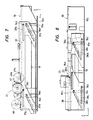
- FIG. 1 shows a perspective view of a whole disk player provided in accordance with the present invention;
- FIGS. 2(a), 2(b), 2(c), 3(a), 3(b), 4(a), 4(b), 5(a) and 5(b) show views for illustrating a magazine of the present invention;
- FIG. 6 shows a plan view of the internal constitution of the disk player of the present invention;
- FIGS.7 and 8 show view taken along lines VII - VII and VIII- VIII shown in FIG. 6;
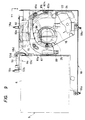
- FIG. 9 shows a partial plan view of the internal constitution of the disk player of the present invention;
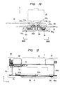
- FIG. 10 shows a sectional view of the disc clamp mechanism of the present invention;
- FIGS. 11 and 12 show a plan view and a front view illustrating the internal constitution of the disk player of the present invention, respectively;
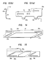
- FIGS. 13(a) and 13(b) show views for illustrating the moving lever in the disc player of the present invention;
- FIGS. 14 and 15 show views for illustrating the moving plates in the disk player of the present invention;
- FIG. 16 shows a sectional view along a line XVI - XVI shown in FIG. 11;
- FIGS. 17(a), 17(b) and 17(c) show views for illustrating the moving member in the disk player of the present invention;
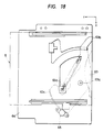
- FIG. 18 shows a partial plan view of the internal constitution of the disk player of the present invention;
- FIGS. 19(a), 19(b), 20(a) and 20(b) show views for illustrating the first and second levers in the disk player of the present invention;
- FIGS. 21, 22, 23, 24 and 25 show views for illustrating the support plates of the pushing means in the disk player of the present invention;
- FIGS. 26(a), 26(b), 26(c) and 27 show views for illustrating the clamp cam of the disk player of the present invention;
- FIGS. 28 and 29 show views for illustrating the pusher of the present invention;
- FIGS. 30(a), 30(b), 30(c), 30(d) and 30(e) show views for illustrating the disk pusher in the disk player of the present invention; and
- FIG. 31 shows a view for illustrating a clamping mechanism of a conventional disk player.
- A disk player of a preferred embodiment of the present invention is hereinafter described with reference to the accompanying drawings. The disk player is a multiple disk player (or a multidisk player) in which a plurality of disks can be housed and desired ones of the housed disks can be sequentially selected and played.
- A
reference numeral 1 in FIG. 1 denotes the disk player as a whole. The front panel 3 of aplayer housing 2 has anoblong opening 3a for loading amagazine 5 as a disk holder into the housing. The opening 3a extends rightward and leftward direction. (An arrow Y indicates the forward direction. An arrow X indicates the leftward direction. An arrow Z indicates the upward direction.) Adisplay section 7 andoperation buttons 6 for operating the disk player are provided on the front panel 3. - As shown in FIGS. 2(a), 2(b) and 2(c), the
magazine 5 comprises amagazine body 8, which is flat and parallelepipedal as a whole and serves as a housing, and a kind of threetrays 11 and another kind of threetrays 12, the total number of which is six. Each of thetrays Disks 10 are borne on the main sides of thetrays trays 11 and 12 (hence thedisks 10 as well) are sequentially disposed at prescribed intervals in an upward and a downward directions (the direction of the arrow Z and the opposite thereof) perpendicular to the disk bearing side of a turntable described hereinafter. Thetrays rotary support shaft 8a provided at the right rear corner of themagazine body 8 and extending upward and downward (in the direction of disposition of the trays), so that each of the trays can be moved into and out of the magazine body along the plane of the main side of the tray. - The constitution of the
magazine 5 is described in detail from now on. Themagazine body 8 is provided with sevenpartitions 8b disposed upward and downward (in the direction of the arrow Z and the opposite thereof). Thetrays partitions 8b. - As shown in FIG. 3(a), the
partitions 8b have smallcircular openings 8c coaxial with each other and located near therotary support shaft 8a. - FIGS. 4(a), 4(b), 5(a) and 5(b) show the details of the
trays openings openings openings 8c of thepartitions 8b. Theopenings 8c of thepartitions 8b are referred to as the first openings. Theopenings trays movable members 13a, which can be moved along the direction (the direction of the arrow Z and the opposite thereof) of disposition of thepartitions 8b, are fitted in theopenings movable members 13a is equal to the interval of disposition of thetrays plate springs 13b provided at the top and bottom of themagazine body 8 urge the sphericalmovable members 13a in such directions as to move the members toward each other. - As shown in FIG. 2(b), a
push lever 14 is provided at the left front corner of themagazine body 8 and extends nearly forward and backward (in the direction of the arrow Y and the opposite thereof). Thepush lever 14 is attached at the front end thereof to themagazine body 8 by apin 14a so that the push lever is swingable. Thepin 14a extends upward and downward (in the direction of the arrow Z and the opposite thereof). The rear end of thepush lever 14 can be smoothly engaged with the free end of each of thetrays spring member 14b is engaged with thepush lever 14 and urges it counterclockwise (as to FIG. 2(b)) to apply a tray pushing force to the lever. Thepush lever 14 is provided with a projection 14c. The projection 14c can be brought into contact with theedge portion 3b along theopening 3a of theplayer housing 2 thereof when themagazine 5 is pulled out of the magazine loading portion in the player housing. When the projection 14c contacts with theedge portion 3b along theopening 3a, the projection 14c acts to swing thepush lever 14 to urge thetrays magazine body 8. - The
push lever 14 and thespring member 14b constitute a push means for pushing thetrays rotary support shaft 8a in themagazine body 8. - The push means, the
openings 8c (first openings) of the partitions of themagazine body 8, theopenings trays movable members 13a and the plate springs 13b constitute a holding mechanism for holding the trays in the housed positions in the magazine body. - As shown in FIGS. 4(a), 4(b), 5(a) and 5(b), the
trays claws magazine body 8. The free end portions of thetrays notches push lever 14 is engaged. The free end portions also have pairs ofjig insertion holes -
Soft members trays trays recesses soft members recesses trays magazine 5 is reduced. - As shown in FIG. 2(c), an engaging
claw 5a is provided almost at the central portion of the right side of themagazine 5 and attached at one end thereof to themagazine body 8 by apin 5b so that the claw can be swung in a prescribed range. Another engagingclaw 5c is attached at one end thereof to the right front corner of themagazine 5 by apin 5d so that the claw can be swung in a prescribed range. The free end of the engagingclaw 5c is urged outward by ahelical spring 5e. The free ends of the engagingclaws edge portion 3b along theopening 3a (refer to FIGS. 1 and 2(b)). - The engaging
claws helical spring 5e constitute a loading prevention means for preventing themagazine 5 from being loaded into the loading portion of theplayer housing 2 when the posture of the magazine is not proper for the loading thereof. When themagazine 5 is being loaded upside down into the loading portion, the engagingclaw 5a swings due to the weight thereof and projects outward from themagazine 5 and the free end of the claw is engaged with theedge portion 3b along theopening 3a to prevent the magazine from being loaded. When themagazine 5 is being loaded with its front side back into the loading portion, the engagingclaw 5c protruded outward by thehelical spring 5e is engaged with theedge portion 3b of theopening 3a to prevent themagazine 5 from being loaded. - Since the loading prevention means is constituted by the engaging
claws helical spring 5e which are simple members, the constitution is simple enough to make it easy to reduce the cost of the disk player. - As shown in FIGS. 2(b) and 3(b), a
circular opening 14e is provided in the projection 14c of thepush lever 14 supported in a swingable manner on themagazine 5. As shown in FIG. 3(b), thehousing body 8 of themagazine 5 is provided with anoverhang portion 8d extending along the bottom of thepush lever 14. A pillar-like projection 8e is provided on theoverhang 8d. Acircular recess 8f is provided in the top of theprojection 8e. A sphericalmovable member 8g is provided in therecess 8f so that themember 8g can be moved upward and downward (in the direction of the arrow Z and the opposite thereof). When thepush lever 14 is in a position shown by a full line in FIG. 2(b), theopening 14e of the projection 14c of the push lever can face therecess 8f and a part of the sphericalmovable member 8g can be fitted in theopening 14e. - The
push lever 14 and the sphericalmovable member 8g constitute a protrusion restricting means for restricting the protrusion of thetrays magazine body 8 when themagazine 5, which serves as a disk holder, is in the posture of being upside down. To be more concrete, when themagazine 5 is in that posture, the sphericalmovable member 8g moves due to the weight thereof and a part of the member enters into theopening 14e of thepush lever 14 to restrict the swing of the push lever to restrain the protrusion of thetrays magazine body 8. - Since the protrusion restricting means is constituted by the
push lever 14 and the sphericalmovable member 8g which are members of simple forms, the constitution is simple enough to make it easy to reduce the cost of the disk player. The sphericalmovable member 8g may not be manufactured for the disk player in particular but may be one on the market. - As shown in FIG. 1, a
chassis 16 is mounted as a support member on abottom plate 15 secured in thehousing 2. Thechassis 16 comprises ahorizontal surface portion 16a extending forward and backward (in the direction of the arrow Y and the opposite thereof) and right and leftward (in the direction of the arrow X and the opposite thereof), and a pair ofvertical surface portions horizontal surface portion 16a and extending forward and backward (in the direction of the arrow Y and the opposite thereof) and upward and downward (in the direction of the arrow Z and the opposite thereof or in the direction of disposition of the trays). - As shown in FIGS. 6 and 9, a moving
member 18 is provided between the rear ends of thevertical surface portions chassis 16 and attached to thevertical surface portions trays 11 and 12). - As shown in FIG. 9, a bearing
plate 22 as a holding member is attached to the top of the movingmember 18. - As shown in FIGS. 8 and 10, the
turntable 23 is mounted on the bearingplate 22. - As shown in FIG. 9, a
carriage 24 bearing an optical pickup means is provided on the bearingplate 22 and attached to the bearing plate so that the carriage can be moved along a plane (which contains thedisk bearing side 23a (shown in FIG. 10) of the turntable in nearly rightward and leftward directions (in the direction of the arrow X and the opposite thereof). - The
turntable 23 is directly rotated by aspindle motor 25 shown in FIGS. 8 and 10. - A carriage drive means for driving the
carriage 24 is provided on the bearingplate 22. - The
turntable 23, thespindle motor 25, thecarriage 24 including the optical pickup means and the carriage drive means constitute a playing means for playing the disk. The playing means is borne on the movingmember 18 so that the playing means is moved together with the moving member upward and downward (in the direction of the arrow Z and the opposite thereof). - As shown in FIG. 10, the
turntable 23 is provided with amagnet 23b. Thepusher 80 of the clamping mechanism has amember 84e made of magnetic material at its yoke portion. Therefore, a clamping force to the disk-shaped pusher of the clamp mechanism is produced by the magnet force of themagnet 23b. Furthermore, according to the present invention, the bearingplate 22 for holding thespindle motor 25 and theturntable 23 is made of a magnetic material and emplaced to face the side of theturntable 23 opposite to the disk bearing side thereof so that the turntable is attracted toward the bearingplate 22 by the magnetic force of themagnet 23b. For that reason, theoutput shaft 25a of thespindle motor 25 and a bearing portion (not shown in the drawings) of the spindle motor for supporting the output shaft are put into tight contact with each other. - As shown in FIGS. 11 and 12, a moving
lever 33 made of a steel plate is attached to the bottom of thechassis 16 so that the lever can be moved forward and backward (in the directions of loading and unloading of the magazine, which are the direction of the arrow Y and the opposite thereof). - FIGS. 13(a) and 13(b) show the details of the moving
lever 33. The rear end portion of the movinglever 33 is provided with aprojection 33a extending downward so that the rear of themagazine 5 can be engaged with theprojection 33a. When the rear of themagazine 5 is engaged with theprojection 33a, the movinglever 33 is moved backward. Thelever 33 is coupled with a helical spring (not shown in the drawings) for applying a forward (in the direction of the arrow Y) biasing force to the lever. - As shown in FIGS. 6 and 11, a pair of detection switches 34 and 35 are provided at the left side of the moving
lever 33 so that theprojections lever 33 can be engaged with the operating elements of the switches to put the elements into action. - The moving
lever 33 and the detection switches 34 and 35 constitute a magazine loading detection means for detecting that themagazine 5 is loaded in the magazine loading portion of theplayer housing 2. - A moving means for moving the moving
member 18 upward and downward (the direction of the arrow Z and the opposite thereof) is described from now on. As shown in FIGS. 6, 7 and 8, a pair of movingplates vertical surface portions chassis 16 so that the moving plates extend forward and backward. FIGS. 14 and 15 show the details of the movingplates - As shown in FIGS. 7 and 8, the moving
plates guide grooves plates guide grooves pins 16d projecting from the outsides of thevertical surface portions chassis 16 which serves as a support member. As a result, the movingplates - As shown in FIGS. 6, 7, 8 and 9, two
pins 18a and other twopins 18a project from the left and right sides of the movingmember 18, respectively. As shown in FIGS. 7 and 8, thepins 18a are movably fitted in fourguide grooves 16e extending upward and downward in the left and rightvertical surface portions chassis 16 which serves as a support member. As a result, the movingmember 18 is guided upward and downward. - The
pins 18a provided on the right and left sides of the movingmember 18 project out of thechassis 16 through theguide grooves 16e thereof. The movingplates pins 18a insteplike cam holes cam hole 37d of the movingplate 37 extends obliquely downward (oppositely to the direction of the arrow Z) and forward (in the direction of the arrow Y) as a whole. Thecam hole 38d of the movingplate 38 extends obliquely upward and forward as a whole. The cam holes 37d and 38d are so provided that the movingmember 18 is moved vertically when the movingplates - As shown in FIGS. 6, 7 and 14, a
rack 37h is provided at the front end of theleft moving plate 37 so that the rack extends in the direction of extension of the movingplate 37. As shown in FIGS. 6 and 7, thesmall gear 40a of adouble gear 40 provided on thechassis 16 is engaged with therack 37h. The movingplate 37 is driven by amotor 45 through a speedreduction gear mechanism 41 including thedouble gear 40. - As shown in FIG. 6, a turning
lever 47 is provided between the left and right movingplates chassis 16 by a pair ofpins 16g projecting from the chassis, so that the lever can be turned about a virtual center 47a. Thelever 47 is pivotally coupled at both ends thereof to the left and right movingplates - The
motor 45, the speedreduction gear mechanism 41, the turninglever 47 and ambient small members related to them constitute a driving force application means for applying driving forces to the movingplates - The driving force application means and the moving
plates member 18 upward and downward (in the direction of the arrow Z and the opposite thereof). - As shown in FIG. 6, a
detection switch 49 is provided on the upper part of the leftvertical surface portion 16b of thechassis 16 to detect that the movingplate 37, which is reciprocated forward and backward, is in the most forwardly moved position (forward movement limit position) thereof. Thedetection switch 49 is put into action when a part of the movingplate 37 is engaged with the operating portion of the switch. - An
address plate 50 having sixslits 50a disposed in the direction of movement of the movingplate 37 is provided at the right of the front end of the moving plate. - A
photosensor 51 for detecting theslits 50a of theaddress plate 50 is provided behind thedetection switch 49. Thedetection switch 49 is herein referred to as the first sensor, while thephotosensor 51 is herein referred to as the second sensor. A slit detection signal obtained from the second sensor is sent to a counter (not shown in the drawings) which counts the number of the slit detection signals. A controller (not shown in the drawings) for automatically controlling the disk player is provided in a prescribed position inside theplayer housing 2. The controller finds out the stopped position of the movingplate 37 in terms of the count of the counter. - The
detection switch 49, which is the first sensor, theaddress plate 50, thephotosensor 51, which is the second sensor, the counter and the controller constitute a positioning mechanism for moving the movingplate 37 to a desired address position and setting the plate in that position. When a movement command is applied as thephotosensor 51 is generating the slit detection signal, the positioning mechanism acts to move the movingplate 37 through a distance corresponding to the difference between a present address and a desired address. When a movement command is applied as thephotosensor 51 is not generating the slit detection signal, the positioning mechanism acts to move the movingplate 37 backward until thedetection switch 49 generates a detection signal, and the positioning mechanism thereafter acts to move the movingplate 37 to a position of desired address. - As shown in FIG. 9, a
tray protruder 53, which is engaged with one of thetrays 11 and 12 (refer to FIG. 2(b) etc.) in themagazine 5 to protrude the tray out of themagazine body 8, is provided at the right front corner of the movingmember 18. The tray protruder 53 is shaped nearly as L-shape as a whole. Apin 53a projecting from thetray protruder 53 is slidably engaged in the arc-shapedguide groove 18d of the movingmember 18 so as to guide thetray protruder 53. The tray protruder 53 is turned about the center of curvature of the arc-shapedguide groove 18d to push the tray by the turnedend 53b of the tray protruder to protrude the tray out of the magazine body. - As shown in FIG. 9, the vertual axis (the center of curvature of the arc-shaped
guide groove 18d) of turning of thetray protruder 53 and the position of therotary support shaft 8a for thetrays tray portion rotary support shaft 8a so that the tray is protruded out of themagazine body 8. - Since the
tray protruder 53 is provided on the movingmember 18, the above-described moving means comprising the movingplates member 18, and the positioning mechanism comprising theaddress plate 50 and so forth constitute a tray protruder moving means for moving thetray protruder 53 together with the movingmember 18 to put the tray protruder in such a position as to engage the tray protruder with thetray disk 10 to be played. - A tray protruder drive means for turning the
tray protruder 53 to protrude thetray magazine body 8 is described from now on. As shown in FIGS. 11 and 16, a movingmember 56 is provided at the right side on the under surface of thechassis 16 and extends forward and backward. The movingmember 56 is attached to thechassis 16 so that the movingmember 56 can be moved in the direction of extension thereof. FIGS. 17(a), 17(b) and 17(c) show the details of the movingmember 56. Arack 56a is provided at the right front corner of the movingmember 56 and extends in the direction of extension of the moving member. Thesmall gear 57a of adouble gear 57 provided on thechassis 16 is engaged with therack 56a. The movingmember 56 is driven by amotor 62 through a speedreduction gear mechanism 58 including thedouble gear 57. The speedreduction gear mechanism 58 and themotor 62 constitute a driving force application means for applying a driving force to the movingmember 56. - As shown in FIGS. 12 and 18, a
swing lever 63 is provided near the bottom of the magazine loading portion of theplayer housing 2 and extends nearly rightward and leftward so that themagazine 5 loaded in the magazine loading portion is protruded out of the portion by the swing lever. Theswing lever 63 is attached nearly at the central portion thereof by apin 63a to anauxiliary chassis 64 provided at the bottom of thechassis 16, so that thelever 63 is swingable. Thepin 63a extends upward and downward (in the direction of the arrow Z and the opposite thereof). Aprojection 63b is provided at the right end of theswing lever 63 and extends upward. Theprojection 63b of theswing lever 63 is brought into contact with the rear of themagazine 5. Agear 63c, the center of curvature of which is on thepin 63a, is provided at the left end of theswing lever 63 and engaged with thebrake gear 65a (shown in FIG. 12) of adamper 65, which applies a braking force by the viscous resistance of a viscous substance such as grease held in the damper. Ahelical spring 63d applies a magazine protruding force to theswing lever 63. - The
swing lever 63, thedamper 65 and thehelical spring 63d constitute a protrusion means for protruding themagazine 5 out of the magazine loading portion of theplayer housing 2. - A locking member 67 (not shown in the drawings) is rotatably provided near the moving
member 56 so that the turning end of the locking member is engaged in theengaging recess 5g (refer to FIGS. 2(b) and 2(c)) of themagazine 5 to lock the magazine in the loaded position thereof in theplayer housing 2. When the movingmember 56 is moved forward, themagazine 5 is unlocked from the locking member 67. - As shown in FIGS. 11 and 16, a
first lever 71 and asecond lever 72 are provided at the right end of thechassis 16 and extend forward and backward (in the direction of the arrow Y and the opposite thereof). Thelevers chassis 16 so that the levers can be reciprocated in the directions of extension thereof. FIGS. 19 and 20 show the details of the first and thesecond levers first lever 71 is for driving the supports of a clamp mechanism described hereinafter. Thesecond lever 72 is for turning the tray protruder 53 (refer to FIG. 9) through anintermediate lever 73 shown in FIGS. 11 and 16. - The
intermediate lever 73 is rotatably supported on thechassis 16 by apin 73a extending upward and downward. Apin 72a projecting from thesecond lever 72 is engaged in acam groove 73b (shown in FIG. 11) provided at the turning end of theintermediate lever 73, so that thelever 73 is turned. Arod 73c extending downward is provided at the other turning end of theintermediate lever 73 and fitted in thehole 53d of the tray protruder 53 (shown in FIG. 9) to turn the tray protruder. - The first and the
second levers member 56. - As shown in FIGS. 11, 16, 17(a) and 17(c), a
first recess 56c is provided in a prescribed position in the movingmember 56. - As shown in FIGS. 11 and 16, the
first lever 71 is provided with afirst opening 71c which can face thefirst recess 56c. Amovable member 74, which can be engaged in thefirst recess 56c, is provided in thefirst opening 71c. - The
first recess 56c, thefirst opening 71c, themovable member 74 and so forth constitute a locking/unlocking means for appropriately locking or unlocking thefirst lever 71 to or from the movingmember 56 depending on the movement thereof. In other words, thefirst lever 71 is moved or stopped together with the movingmember 56 depending on the distance of the movement thereof, to drive the clamp mechanism described hereinafter. The locking/unlocking means is described in detail in the United States Patent 4,631,716. - As shown in FIGS. 11, 16, 17(a) and 17(c), the moving
member 56 is provided with a second and athird recesses second lever 72 is provided with a second and athird openings third recesses movable member 75 is provided between thesecond recess 56d and thesecond opening 72d. Themovable member 76 is provided between thethird recess 56e and thethird opening 72e. - The second and the
third recesses third openings movable members second lever 72 to or from the movingmember 56 depending on the movement thereof. In other words, thesecond lever 72 is moved or stopped together with the movingmember 56 depending on the distance of the movement thereof, to drive the tray protruder 53 (refer to FIG. 9). - The locking/unlocking means, the
second lever 72, the movingmember 56 and the driving force application means including themotor 62 and so forth to apply the driving force to the movingmember 56 constitute a tray protruder drive means for turning the tray protruder 53 (shown in FIG. 9) to protrude thetray 11 or 12 (refer to FIGS. 4 and 5) out of themagazine body 8. - The tray protruder drive means, the chassis being a support member, the moving
member 18, thetray protruder 53 and the tray protruder moving means including the movingplates tray magazine body 8 as the tray remains bearing thedisk 10 to be played. - As shown in FIGS. 9, 21, 22 and 23, a pair of plate-shaped
supports member 18 and extending forward and backward (in the direction of the arrow Y and the opposite thereof) and rightward and leftward (in the direction of the arrow X and the opposite thereof). The supports 78 and 79 are attached to the movingmember 18 bypins disk bearing side 23a (shown in FIG. 10) of the turntable 23 (refer to FIGS. 8 and 10). FIGS. 24 and 25 show the details of thesupports pusher 80 is rotatably attachable to the free ends of thesupports disk 10 opposite to theturntable 23 to clamp the disk in cooperation with the turntable. To be more concrete, the free end of thesupport 78 is located in contact with the side of aflange 81a opposite to the disk pushing side thereof. Theflange 81a is provided on thebody 81 of thepusher 80. The free end of theother support 79 is located in contact with the disk pushing side of theflange 81a. Thepusher 80 is vertically pinched between the free ends of thesupports - As shown in FIGS. 9 and 21, a
clamp cam 82 shaped as a bow is provided over thesupports pins 82a so that theclamp cam 82 is moved about its center of curvature. FIGS. 26(a), 26(b), 26(c) and 27 show the details of theclamp cam 82. - As shown in FIG. 26(c) and 27, the nearly central part of the
clamp cam 82 is provided withcam portions columnar projections supports clamp cam 82 is reciprocated to drive thesupports pusher 80 to and from theturntable 23. Thecam portions supports pusher 80 after the pusher is certainly attracted and tightened to theturntable 23 by a magnet force of themagnet 23b when the disc is to be clamped and that the pusher is separated from the turntable after the pinching of the pusher between the supports is completed when the disc is to be released from its clamped state. - As shown in FIGS. 21, 26(a) and 26(c), a
U-shaped notch 82f is provided at one end of theclamp cam 82 and smoothly engaged with aprojection 71e provided on the first lever 71 (shown in FIGS. 11, 16, 19(a) and 19(b)) and extending downward. Thefirst lever 71 is reciprocated to move theclamp cam 82 to swing thesupports - The
clamp cam 82, thefirst lever 71, the moving member 56 (shown in FIG. 17, etc.), the locking/unlocking means including themovable member 74 and so forth to appropriately lock or unlock thefirst lever 71 and the movingmember 56 to or from each other depending on the movement of the moving member, and the driving force application means including themotor 62 and so forth to apply the driving force to the movingmember 56 constitute a drive means for driving thesupports - The drive means and the
supports pusher 80 to and from theturntable 23. - The pusher moving means and the
pusher 80 constitute the clamp mechanism for clamping thedisk 10. - As shown in FIGS. 22 and 23, springs 78f and 79f are provided to urge the
supports pusher 80 toward thedisk bearing side 23a (refer to FIG. 10) of theturntable 23. - As shown in FIG. 10 indicating a view taken on line X-X shown in FIG. 21, a slope or tapered
portion 78g is provided at the free end of thesupport 78 so that the slope is engaged with the peripheral portion (of the body 81) of thepusher 80 to position the pusher in a plane parallel with thedisk bearing side 23a of theturntable 23. Thepusher 80 can thus be accurately aligned to theturntable 23. - The forms of the
turntable 23 and thepusher 80 are described in detail from now on. As shown in FIG. 23, thepusher 80 is provided with adisk centering projection 84, which is fitted in the center hole of thedisk 10 to center the disk. Theturntable 23 is provided with arecess 23c, in which thedisk centering projection 84 is fitted when thedisk 10 is clamped on the turntable. Because of such constitution, thedisk 10 is prevented from deviating in the direction parallel with thedisk bearing side 23a of theturntable 23. - FIG. 28 shows a view taken along line XXVIII-XXVIII shown in FIG. 10. FIG. 29 shows a sectional view along a line XXIX-XXIX shown in FIG. 28. As shown in FIGS. 28 and 29, the
disk centering projection 84 of the pusher is movable in a prescribed range along the axis of gyration of the pusher. Thedisk centering projection 84 is attached to thebody 81 of thepusher 80 through a cam means which comprises threecam surfaces 84a provided on thedisk centering projection 84 and threespherical guide members 85 provided on thebody 81 of thepusher 80 so as to slide in contact with the cam surfaces 84a. When thedisk centering projection 84 is moved along the axis of gyration of thepusher 80, the projection is rotated about the axis. - As shown in FIG. 28, a
spring 84d is provided as an urging means for urging thedisk centering projection 84 to rotate it to project upward (in the direction of the arrow Z) from thebody 81 of thepusher 80. - The three
spherical guides 85 are emplaced at equal intervals in the direction of gyration of thepusher 80. As shown in FIGS. 10 and 29, a part of each of thespherical guides 85 project at the disk pushing side of thebody 81 of thepusher 80 so that the part is located in contact with the surface of thedisk 10. For that reason, thedisk 10 is supported at three points by thepusher 80 so that the disk is accurately clamped. - The above-described clamp mechanism acts as a disk moving means so that the
disk 10 borne on thetray magazine body 8 by the tray protrusion means is moved in an upward direction (the direction of the arrow Z) perpendicular to thedisk bearing side 23a (refer to FIG. 10) of theturntable 23. - The disk moving means and the tray protrusion means constitute a disk takeout and conveyance mechanism for sequentially selecting each of the desired
disks 10 in themagazine 5 and conveying the selected disk onto thedisk bearing side 23a of theturntable 23. - As shown in FIG. 9, a disk
pusher drive cam 87 shaped nearly as a bow is provided on the movingmember 18 and attached to the movingmember 18 by apin 87a so that thecam 87 is moved about its center of curvature. FIGS. 30(a), 30(b) and 30(c) show the details of the diskpusher drive cam 87. - As shown in FIGS. 9, 30(a) and 30(c), an
opening 87c is provided at one end of the diskpusher drive cam 87. Apin 82h (refer to FIGS. 26(a) and 26(b)) projecting upward from the end of theclamp cam 82 is smoothly fitted in theopening 87c so that the diskpusher drive cam 87 is moved as theclamp cam 82 is moved. The diskpusher drive cam 87 is for driving a disk pusher 88 (shown in FIGS. 9, 30(d) and 30(e)), whosefree end 88a is brought into contact with the side (facing thedisk bearing side 23a of the turntable 23) of the disk moved by the disk moving means (the clamp mechanism) in a vertical direction perpendicular to thedisk bearing side 23a (refer to FIG. 10). As a result, thedisk pusher 88 maintains the moveddisk 10 to be parallel to thedisk bearing side 23a of theturntable 23. Thedisk pusher 88 is vertically swung about asupport pin 88b when the diskpusher drive cam 87 is moved along the curvature thereof. - As shown in FIGS. 6 and 11, the
chassis 16 is provided with twodetection switches member 56 as the switches are engaged with the moving member driven by themotor 62. - Detection signals sent from the detection switches 34, 35, 49, 89 and 90 and the photosensor 51 are entered into the above-mentioned controller (not shown in the drawings), which sends out operation signals to operate the
motors turntable 23 at prescribed timing described hereinafter. - The operation of the multidisk player with the above-described constitution is now briefly described in the sequence of playing steps. When the disk to be played is first appointed by manipulating the
operation buttons 6 shown in FIG. 1, a driving voltage is applied to the motor 45 (refer to FIG. 6) to start moving the movingplates pins 18a movably fitted in thesteplike cam grooves plates guide grooves 16e of thechassis 16 are moved up or down so that the movingmember 18 having thepins 18a is moved up or down. For that reason, the tray protruder 53 (shown in FIG. 9) provided on the movingmember 18 reaches a position in which the tray protruder is engageable with thetray - When the
tray protruder 53 is thus put in the position in which thetray protruder 53 can be engaged with the tray bearing the disk to be played, the rotation of the motor 62 (refer to FIG. 11) is started to drive the movingmember 56 backward (in the direction opposite to that of the arrow Y). At that time, the movingmember 56 remains locked to thesecond lever 72 by the locking/unlocking means including themovable members 75 and 76 (refer to FIGS. 16 etc.), and thefirst lever 71 is not yet locked to the movingmember 56. For that reason, only thesecond lever 72 is moved backward together with the movingmember 56 to turn thetray protruder 53 counterclockwise as to FIG. 9. Consequently, the tray (for example, the tray 12) bearing the disk to be played is protruded out of themagazine body 8, as shown in FIG. 2(b), so that the disk is moved to a position in which the disk is coaxial with thedisk bearing side 23a (refer to FIG. 10) of theturntable 23 or located immediately under the disk bearing side. - Then, the moving
member 56 is moved backward further oppositely to the direction of the arrow Y, and thesecond lever 72 is unlocked from the moving member and thefirst lever 71 is simultaneously locked to the moving member. Therefore, thefirst lever 71 is moved backward together with the movingmember 56 so that thesupports 78 and 79 (shown in FIGS. 21 etc.) of the clamp mechanism is swung upward (in the direction of the arrow Z). For that reason, the disk is lifted upward so that it is clamped on theturntable 23. As a result, the disk can be played by operating theturntable 23 and the carriage 24 (refer to FIG. 9). - After the disk is played, it is housed back in the
magazine body 8. Since the operation of housing the disk back in themagazine body 8 is performed by inversely taking the steps of the above-described operation of loading the disk on theturntable 23, the operation of housing the disk back in the magazine body is not described in detail. Such operations are repeated depending on the number of appointed disks or tunes. - As described above, in a disk player provided in accordance with the present invention, a clamp mechanism for clamping a
disk 10 comprises apusher 80, which acts to clamp the disk in cooperation with aturntable 23, and a pusher moving means for tightening and loosening the pusher to and from the turntable. The pusher moving means comprises a pair ofsupports disk bearing side 23a of theturntable 23 and whose free ends are brought into contact with the disk pushing side of the pusher and the opposite side thereof to pinch the pusher therebetween, and drive means for driving the supports. Because of such constitution, thepusher 80 keeps parallel with the disk bearing side of the turntable whatever position the pusher takes. For that reason, the stroke of the swing of thesupports - Furthermore, since a mechanism for keeping the pusher parallel with the disk bearing side of the turntable is substantially made of only the pair of supports, the cost of the disk player can be also reduced.
- Furthermore, according to the present invention, when the disc is to be clamped, the pushing
means 80 is attracted and tightened to theturntable 23 by a magnet force of the magnet in theturntable 23 before the pair ofsupport members means 80. When the disc is to be released from its clamped state, the pair ofsupport members turntable 23. - Therefore, even if the disk player as a whole is set upside down, clamping of the disc is accomplised certainly. Furthermore, when the disc is to be released from the clamping mechanism, the pushing means is separated from the turntable, with the pair of supports pinching the pushing means therebetween. Therefore, noise is not produced when the pushing means is separated from the turntable.
- In the disc player of the present invention, a
magnet 23b for producing a disc clamping force is provided in aturntable 23. The holding means (bearing plate 22) for holding a spindle motor bearing and rotating theturntable 23 is made of magnetic material. The holding means 22 is placed so as to face the side of theturntable 23 which is a reverse side of its disk mounting side. - By the above-described construction, the output shaft of the spindle motor and the bearing portion in the spindle motor for supporting the output shaft are put into tight contact with each other. As a result, the turntable can be rotated without shaking or rolling. As described above, in the present invention, in order to make the output shaft of the spindle motor contact tightly with the bearing member in the spindle motor, there is not provided additional particular member. Therefore, the cost of producing the disk player is reduced.
- Furthermore, according to the present invention, a multidisk player comprises a player housing 2, playing means for playing the disk, the playing means having a turntable 23 for mounting a disk thereon and being placed inside of the player housing, disk holding means (magazine 5) for holding a plurality of disks 10, the disk holding means capable of being inserted into the player housing to be loaded at a loading portion inside of the player housing, the disk holding means comprising a housing portion (magazine body 8) and a plurality of tray members 11 and 12 for bearing disks, the tray members being provided inside of the housing portion in such a manner that the tray members are disposed in a direction nearly perpendicular to the disc bearing side 23a of the turntable, the tray members being capable of protruding out of the housing portion and disk takeout and conveyance mechanism for taking a disk out of the disk holding means and conveying the disk to a playing position, the disk take out and conveyance mechanism having supporting member (chassis 16) extending in a direction of the disposition of the tray members, moving member 18 provided on the supporting member movably in the direction of the disposition of the tray members, protruding means 53 for protruding the tray member out of the housing portion of the tray holding means by engaging its one rotational end with the tray member in the tray holding means, the protruding means being rotatably provided on the moving member, moving means for moving the protruding means together with the moving member to a position where the one rotational end of the protruding means is engageable with the tray member, pushing means 80 for clamping the disc in cooperation with the turntable, supporting means 78 and 79 for rotatably supporting the pushing means, the supporting means being movable in planes nearly perpendicular to the disc bearing side of the turntable, first lever means 71 for moving the supporting means 78 and 79, the first lever means being provided on the supporting member (chassis 16) movably in the disk holding means (magazine 5) loading direction, second lever means 72 for rotating the tray protruding means 53, the second lever means being provided on the supporting member 16 movably in the first lever moving direction, moving means 56 for moving the first and second lever means, the first and second lever means moving means being provided on the supporting member movably in the first and second lever means moving direction, driving force application means (motor 62, etc.) for applying driving force to the first and second lever moving means, and locking/unlocking means (movable members 74, 75 and 76, etc.) for selectively lock/unlock the first and second lever means with respect to the moving means 56 depending on the movement of the moving means.
- The playing means including the
turntable 23 and the pickup means, etc. are totally moved together with the movingmember 18 in the direction of the arrangement of thetrays trays disk 10 on the tray is moved to be placed immediately under theturntable 23. Then, the supportingmeans disk 10 with the pushingmeans 80 and set thedisc 10 on theturntable 23. - In this construction, since the moving
means 56, the first and second lever means 71 and 72 and the lock/unlocking means are provided, it meakes possible to reduce the size of the disc player, as will be described below. If there are not provided the first and second lever means but only the movingmeans 56 is provided, the moving means 56 directly moves the supportingmeans means means 56. - However, according to the present invention, as described above, there are provided not only the moving means 56 but also the first and second lever means 71 and 72. As a result, the stroke of the movement of the moving means required is reduced. Furthermore, since the linear space required for moving the moving means is not on the same line with the linear spaces required for moving the first and second lever means, the total volume of the linear spaces required for moving them is reduced, to thereby make the disc player compact.
Claims (1)
- A multidisk player comprising:
a player housing (2);
playing means, (23,24,25) for playing the disk (10), said playing means having a turntable (23) for mounting a disk (10) thereon and being placed inside of said player housing (2);
disk holding means (5) for holding a plurality of disks (10), said disk holding means (5) capable of being inserted into said player housing (2) to be loaded at a loading portion inside of said player housing (2), said disk holding means (5) comprising a housing portion (8) and a plurality of tray members (11,12) for bearing disks (10), said tray members (11,12) being provided inside of said housing portion (8) in such a manner that said tray members (11,12) are disposed in a direction nearly perpendicular to the disc bearing side of said turntable (23), said tray members (11,12) being capable of protruding out of said housing portion (8); and
disk takeout and conveyance mechanism (16,18,53) for taking a disk (10) out of said disk holding means (5) and conveying the disk (10) to a playing position, said disk take out and conveyance mechanism (16,18,53) having a supporting member (16) extending in a direction of the disposition of said tray members (11,12), moving member (18) provided on said supporting member (16) movably in the direction of the disposition of said tray members (11,12), protruding means (53) for protruding said tray member (11,12) out of said housing portion (8) of said tray holding means (5) by engaging its one rotational end with said tray member (11,12) in said tray holding means (5), said protruding means (53) being rotatably provided on said moving member (18), moving means for moving said protruding means (53) together with said moving member (18) to a position where said one rotational end of said protruding means (53) is engageable with said tray member (11,12), pushing means (80) for clamping the disc (10) in cooperation with said turntable (23), supporting means (78,79) for rotatably supporting said pushing means (80), said supporting means (78,79) being movable in planes nearly perpendicular to the disc bearing side of said turntable (23), first lever means (71) for moving said supporting means (78,79), said first lever means (71) being provided on said supporting member (16) movably in said disk holding means loading direction, second lever means (72) for rotating said tray protruding means (53), said second lever means (72) being provided on said supporting member (16) movably in said first lever means moving direction, moving means (37,38) for moving said first and second lever means (71,72), said first and second lever means moving means (37,38) being provided on said supporting member (16) movably in said first and second lever means moving direction, driving force application means (41,45,47) for applying driving force to said first and second lever moving means (37,38), and locking/unlocking means (56d,56e,72d,72e,75,76) for selectively lock/unlock said first and second lever means (71,72) with respect to said moving means (37,38) depending on the movement of said moving means (37,38).
Applications Claiming Priority (8)
| Application Number | Priority Date | Filing Date | Title |
|---|---|---|---|
| JP75011/86 | 1986-04-01 | ||
| JP7501586A JPS62283446A (en) | 1986-04-01 | 1986-04-01 | Multidisk player |
| JP75012/86 | 1986-04-01 | ||
| JP7501286A JPS62283445A (en) | 1986-04-01 | 1986-04-01 | Disk player |
| JP7501186A JPS62283444A (en) | 1986-04-01 | 1986-04-01 | Disk player |
| JP75015/86 | 1986-04-01 | ||
| JP61075014A JPS62283450A (en) | 1986-04-01 | 1986-04-01 | Multidisk player |
| JP75014/86 | 1986-04-01 |
Related Parent Applications (1)
| Application Number | Title | Priority Date | Filing Date |
|---|---|---|---|
| EP87104839.3 Division | 1987-04-01 |
Publications (3)
| Publication Number | Publication Date |
|---|---|
| EP0469643A2 EP0469643A2 (en) | 1992-02-05 |
| EP0469643A3 EP0469643A3 (en) | 1992-04-01 |
| EP0469643B1 true EP0469643B1 (en) | 1994-03-23 |
Family
ID=27465772
Family Applications (3)
| Application Number | Title | Priority Date | Filing Date |
|---|---|---|---|
| EP91118183A Expired - Lifetime EP0469643B1 (en) | 1986-04-01 | 1987-04-01 | Disk player |
| EP19910118164 Withdrawn EP0469642A3 (en) | 1986-04-01 | 1987-04-01 | Disk player |
| EP87104839A Expired - Lifetime EP0240926B1 (en) | 1986-04-01 | 1987-04-01 | Disk player |
Family Applications After (2)
| Application Number | Title | Priority Date | Filing Date |
|---|---|---|---|
| EP19910118164 Withdrawn EP0469642A3 (en) | 1986-04-01 | 1987-04-01 | Disk player |
| EP87104839A Expired - Lifetime EP0240926B1 (en) | 1986-04-01 | 1987-04-01 | Disk player |
Country Status (3)
| Country | Link |
|---|---|
| US (1) | US4839764A (en) |
| EP (3) | EP0469643B1 (en) |
| DE (2) | DE3784957T2 (en) |
Families Citing this family (13)
| Publication number | Priority date | Publication date | Assignee | Title |
|---|---|---|---|---|
| JPH0447805Y2 (en) * | 1987-09-24 | 1992-11-11 | ||
| DE3732940A1 (en) * | 1987-09-30 | 1989-04-20 | Thomson Brandt Gmbh | IN / EXTENSION DEVICE FOR A RECORDING CARRIER |
| NL8800360A (en) * | 1988-02-15 | 1989-09-01 | Philips Nv | CASSETTE FOR STORING SEVERAL DISC-SHAPED PLATES, IN PARTICULAR OPTICAL PLATES. |
| US5245602A (en) * | 1988-03-04 | 1993-09-14 | Pioneer Electronic Corporation | Front loading disk player |
| EP0330731A3 (en) * | 1988-03-04 | 1991-01-23 | Pioneer Electronic Corporation | Front loading disk player |
| DE68920415T2 (en) * | 1988-11-14 | 1995-08-17 | Pioneer Electronic Corp | Playback device with a magazine for records. |
| JPH02292773A (en) * | 1989-05-02 | 1990-12-04 | Pioneer Electron Corp | Player for housing plural disks |
| US5191569A (en) * | 1989-05-15 | 1993-03-02 | Pioneer Electronic Corporation | Disk playback device |
| JPH07262674A (en) * | 1990-12-19 | 1995-10-13 | Pioneer Electron Corp | Magazine disk player |
| US5177731A (en) * | 1990-12-21 | 1993-01-05 | Tamashim Denki Co, Ltd. | Disk drive and pickup unit for an optical disk player |
| JPH04370563A (en) * | 1991-06-20 | 1992-12-22 | Matsushita Electric Ind Co Ltd | Disk changer device |
| JP2862765B2 (en) * | 1993-07-28 | 1999-03-03 | 富士通株式会社 | Magnetic tape device and automatic cleaning method in the device |
| US7433150B2 (en) | 2003-10-31 | 2008-10-07 | Tandberg Data Asa | Data cartridge magazine and method of operation thereof |
Family Cites Families (22)
| Publication number | Priority date | Publication date | Assignee | Title |
|---|---|---|---|---|
| US4170031A (en) * | 1978-03-20 | 1979-10-02 | International Business Machines Corporation | Loading mechanism for magnetic diskettes |
| DE2909099A1 (en) * | 1979-03-08 | 1980-09-11 | Licentia Gmbh | Record player for video or audio discs - has magnet on drive part attracting magnet in casing that holds inserted disc |
| US4453188A (en) * | 1981-04-10 | 1984-06-05 | Amlyn Corporation | Disk drive |
| JPS5814386A (en) * | 1981-07-20 | 1983-01-27 | Toshiba Corp | Digital disc player |
| DE3147324A1 (en) * | 1981-11-28 | 1983-06-01 | Basf Ag, 6700 Ludwigshafen | DRIVE FOR FLEXIBLE RECORD CARRIERS WITH CENTRAL CLAMPING OPENING |
| BE892073A (en) * | 1982-02-09 | 1982-05-27 | Staar Sa | DEVICE FOR HOLDING A MAGNETIC LOCK FOR A TURNTABLE |
| JPS5929309A (en) | 1982-08-12 | 1984-02-16 | 日本碍子株式会社 | Corona shielding ring unit |
| US4539671A (en) * | 1982-09-24 | 1985-09-03 | Sony Corporation | Recording and/or reproducing apparatus for a disk |
| US4481618A (en) * | 1982-11-19 | 1984-11-06 | U.S. Philips Corporation | Loading device for a recording and/or playback apparatus |
| JPS6040560A (en) * | 1983-08-12 | 1985-03-02 | Pioneer Electronic Corp | Disk player |
| JPS6040567A (en) * | 1983-08-12 | 1985-03-02 | Canon Inc | Recording or reproducing device |
| JPS6040052U (en) * | 1983-08-24 | 1985-03-20 | 日本マランツ株式会社 | Disc clamp mechanism of compact disc player |
| JPS6072908A (en) | 1983-09-30 | 1985-04-25 | Yotsukaichi Polymer:Kk | Production of ethylene copolymer |
| EP0145052B1 (en) * | 1983-11-08 | 1988-02-03 | Koninklijke Philips Electronics N.V. | A disc-record player with a loading device for loading a disc into the record player |
| JPS6098140U (en) * | 1983-12-07 | 1985-07-04 | 日本マランツ株式会社 | Disc clamp device for compact disc player |
| DE3505339A1 (en) | 1984-02-17 | 1985-08-29 | Pioneer Electronic Corp., Tokio/Tokyo | EXCHANGE MECHANISM |
| JPS60254450A (en) * | 1984-05-31 | 1985-12-16 | Sony Corp | Disk pack for disk changer |
| US4570254A (en) * | 1984-07-03 | 1986-02-11 | Staar S.A. | Drive motor having moving rotor for compact disc player apparatus |
| JPH0634287B2 (en) * | 1984-08-07 | 1994-05-02 | 三菱電機株式会社 | Continuous drive for disk-shaped recording medium |
| JPH0333979Y2 (en) * | 1984-09-14 | 1991-07-18 | ||
| DE3645041C2 (en) * | 1985-03-08 | 1992-01-23 | Pioneer Electronic Corp., Tokio/Tokyo, Jp | |
| DE3672001D1 (en) * | 1985-07-12 | 1990-07-19 | Pioneer Electronic Corp | DISK DEVICE. |
-
1987
- 1987-04-01 EP EP91118183A patent/EP0469643B1/en not_active Expired - Lifetime
- 1987-04-01 EP EP19910118164 patent/EP0469642A3/en not_active Withdrawn
- 1987-04-01 DE DE8787104839T patent/DE3784957T2/en not_active Expired - Fee Related
- 1987-04-01 US US07/032,694 patent/US4839764A/en not_active Expired - Lifetime
- 1987-04-01 DE DE3789460T patent/DE3789460T2/en not_active Expired - Fee Related
- 1987-04-01 EP EP87104839A patent/EP0240926B1/en not_active Expired - Lifetime
Also Published As
| Publication number | Publication date |
|---|---|
| DE3789460T2 (en) | 1994-06-30 |
| EP0469643A3 (en) | 1992-04-01 |
| DE3789460D1 (en) | 1994-04-28 |
| EP0240926A3 (en) | 1989-07-26 |
| US4839764A (en) | 1989-06-13 |
| DE3784957D1 (en) | 1993-04-29 |
| EP0469642A3 (en) | 1992-04-01 |
| EP0240926B1 (en) | 1993-03-24 |
| EP0469642A2 (en) | 1992-02-05 |
| EP0469643A2 (en) | 1992-02-05 |
| DE3784957T2 (en) | 1993-07-01 |
| EP0240926A2 (en) | 1987-10-14 |
Similar Documents
| Publication | Publication Date | Title |
|---|---|---|
| EP0469643B1 (en) | Disk player | |
| US5136563A (en) | Magazine holder in a CD player | |
| EP0225766B1 (en) | Disk cartridge | |
| EP0305035B1 (en) | Vibration-resistant multiple-disc player | |
| KR101106642B1 (en) | Optical disc loading apparatus for optical disc player | |
| JP3608866B2 (en) | Auto changer | |
| JPH02292773A (en) | Player for housing plural disks | |
| EP0548465B1 (en) | Laser disk player | |
| JPH0150024B2 (en) | ||
| JPH07114059B2 (en) | Multi-disc player | |
| JPH0432460B2 (en) | ||
| JPH0150025B2 (en) | ||
| JP2543573Y2 (en) | Swing mechanism | |
| JPH0447393B2 (en) | ||
| JP2536834B2 (en) | Multi-disc player | |
| JPS62283449A (en) | Disk player | |
| JPS62283445A (en) | Disk player | |
| JP3449916B2 (en) | Disk playing device | |
| JPS63167468A (en) | Multidisk player | |
| JPH0346908B2 (en) | ||
| JP2000187914A (en) | Disk loading device | |
| JPH02206059A (en) | Magazine disk player | |
| JPS61236086A (en) | Disc player | |
| JPH06105528B2 (en) | Disk clamp device | |
| JPH0572022B2 (en) |
Legal Events
| Date | Code | Title | Description |
|---|---|---|---|
| PUAI | Public reference made under article 153(3) epc to a published international application that has entered the european phase |
Free format text: ORIGINAL CODE: 0009012 |
|
| 17P | Request for examination filed |
Effective date: 19911024 |
|
| AC | Divisional application: reference to earlier application |
Ref document number: 240926 Country of ref document: EP |
|
| AK | Designated contracting states |
Kind code of ref document: A2 Designated state(s): BE DE FR GB IT NL |
|
| PUAL | Search report despatched |
Free format text: ORIGINAL CODE: 0009013 |
|
| AK | Designated contracting states |
Kind code of ref document: A3 Designated state(s): BE DE FR GB IT NL |
|
| 17Q | First examination report despatched |
Effective date: 19930513 |
|
| GRAA | (expected) grant |
Free format text: ORIGINAL CODE: 0009210 |
|
| AC | Divisional application: reference to earlier application |
Ref document number: 240926 Country of ref document: EP |
|
| AK | Designated contracting states |
Kind code of ref document: B1 Designated state(s): BE DE FR GB IT NL |
|
| PGFP | Annual fee paid to national office [announced via postgrant information from national office to epo] |
Ref country code: GB Payment date: 19940323 Year of fee payment: 8 |
|
| PGFP | Annual fee paid to national office [announced via postgrant information from national office to epo] |
Ref country code: BE Payment date: 19940331 Year of fee payment: 8 |
|
| PGFP | Annual fee paid to national office [announced via postgrant information from national office to epo] |
Ref country code: FR Payment date: 19940428 Year of fee payment: 8 |
|
| REF | Corresponds to: |
Ref document number: 3789460 Country of ref document: DE Date of ref document: 19940428 |
|
| ITTA | It: last paid annual fee | ||
| PGFP | Annual fee paid to national office [announced via postgrant information from national office to epo] |
Ref country code: NL Payment date: 19940430 Year of fee payment: 8 |
|
| PGFP | Annual fee paid to national office [announced via postgrant information from national office to epo] |
Ref country code: DE Payment date: 19940530 Year of fee payment: 8 |
|
| ITF | It: translation for a ep patent filed |
Owner name: SOCIETA' ITALIANA BREVETTI S.P.A. |
|
| ET | Fr: translation filed | ||
| PLBE | No opposition filed within time limit |
Free format text: ORIGINAL CODE: 0009261 |
|
| STAA | Information on the status of an ep patent application or granted ep patent |
Free format text: STATUS: NO OPPOSITION FILED WITHIN TIME LIMIT |
|
| 26N | No opposition filed | ||
| PG25 | Lapsed in a contracting state [announced via postgrant information from national office to epo] |
Ref country code: GB Effective date: 19950401 |
|
| PG25 | Lapsed in a contracting state [announced via postgrant information from national office to epo] |
Ref country code: BE Effective date: 19950430 |
|
| BERE | Be: lapsed |
Owner name: PIONEER ELECTRONIC CORP. Effective date: 19950430 |
|
| PG25 | Lapsed in a contracting state [announced via postgrant information from national office to epo] |
Ref country code: NL Effective date: 19951101 |
|
| GBPC | Gb: european patent ceased through non-payment of renewal fee |
Effective date: 19950401 |
|
| PG25 | Lapsed in a contracting state [announced via postgrant information from national office to epo] |
Ref country code: FR Effective date: 19951229 |
|
| NLV4 | Nl: lapsed or anulled due to non-payment of the annual fee |
Effective date: 19951101 |
|
| PG25 | Lapsed in a contracting state [announced via postgrant information from national office to epo] |
Ref country code: DE Effective date: 19960103 |
|
| REG | Reference to a national code |
Ref country code: FR Ref legal event code: ST |
|
| PG25 | Lapsed in a contracting state [announced via postgrant information from national office to epo] |
Ref country code: IT Free format text: LAPSE BECAUSE OF NON-PAYMENT OF DUE FEES;WARNING: LAPSES OF ITALIAN PATENTS WITH EFFECTIVE DATE BEFORE 2007 MAY HAVE OCCURRED AT ANY TIME BEFORE 2007. THE CORRECT EFFECTIVE DATE MAY BE DIFFERENT FROM THE ONE RECORDED. Effective date: 20050401 |