EP0469593A1 - Process for the removal of nitrogen oxides from flue gases - Google Patents
Process for the removal of nitrogen oxides from flue gases Download PDFInfo
- Publication number
- EP0469593A1 EP0469593A1 EP91112913A EP91112913A EP0469593A1 EP 0469593 A1 EP0469593 A1 EP 0469593A1 EP 91112913 A EP91112913 A EP 91112913A EP 91112913 A EP91112913 A EP 91112913A EP 0469593 A1 EP0469593 A1 EP 0469593A1
- Authority
- EP
- European Patent Office
- Prior art keywords
- catalyst
- section
- flue gas
- reducing agent
- traversed
- Prior art date
- Legal status (The legal status is an assumption and is not a legal conclusion. Google has not performed a legal analysis and makes no representation as to the accuracy of the status listed.)
- Granted
Links
- MWUXSHHQAYIFBG-UHFFFAOYSA-N nitrogen oxide Inorganic materials O=[N] MWUXSHHQAYIFBG-UHFFFAOYSA-N 0.000 title claims abstract description 66
- 239000003546 flue gas Substances 0.000 title claims abstract description 42
- 238000000034 method Methods 0.000 title claims abstract description 20
- 239000003054 catalyst Substances 0.000 claims abstract description 69
- UGFAIRIUMAVXCW-UHFFFAOYSA-N Carbon monoxide Chemical compound [O+]#[C-] UGFAIRIUMAVXCW-UHFFFAOYSA-N 0.000 claims abstract description 37
- 239000003638 chemical reducing agent Substances 0.000 claims abstract description 14
- 238000010531 catalytic reduction reaction Methods 0.000 claims abstract description 9
- QGZKDVFQNNGYKY-UHFFFAOYSA-N Ammonia Chemical compound N QGZKDVFQNNGYKY-UHFFFAOYSA-N 0.000 claims description 54
- 229910021529 ammonia Inorganic materials 0.000 claims description 27
- VYPSYNLAJGMNEJ-UHFFFAOYSA-N Silicium dioxide Chemical compound O=[Si]=O VYPSYNLAJGMNEJ-UHFFFAOYSA-N 0.000 claims description 4
- GWEVSGVZZGPLCZ-UHFFFAOYSA-N Titan oxide Chemical compound O=[Ti]=O GWEVSGVZZGPLCZ-UHFFFAOYSA-N 0.000 claims description 4
- GNTDGMZSJNCJKK-UHFFFAOYSA-N divanadium pentaoxide Chemical compound O=[V](=O)O[V](=O)=O GNTDGMZSJNCJKK-UHFFFAOYSA-N 0.000 claims description 4
- 239000000463 material Substances 0.000 claims description 3
- PNEYBMLMFCGWSK-UHFFFAOYSA-N aluminium oxide Inorganic materials [O-2].[O-2].[O-2].[Al+3].[Al+3] PNEYBMLMFCGWSK-UHFFFAOYSA-N 0.000 claims description 2
- 239000000377 silicon dioxide Substances 0.000 claims description 2
- 238000006243 chemical reaction Methods 0.000 description 5
- 230000003197 catalytic effect Effects 0.000 description 4
- 239000007789 gas Substances 0.000 description 4
- 238000007789 sealing Methods 0.000 description 4
- 238000006722 reduction reaction Methods 0.000 description 3
- 239000011149 active material Substances 0.000 description 2
- BIGPRXCJEDHCLP-UHFFFAOYSA-N ammonium bisulfate Chemical compound [NH4+].OS([O-])(=O)=O BIGPRXCJEDHCLP-UHFFFAOYSA-N 0.000 description 2
- 238000002485 combustion reaction Methods 0.000 description 2
- 150000001875 compounds Chemical class 0.000 description 2
- 230000000717 retained effect Effects 0.000 description 2
- IJGRMHOSHXDMSA-UHFFFAOYSA-N Atomic nitrogen Chemical compound N#N IJGRMHOSHXDMSA-UHFFFAOYSA-N 0.000 description 1
- 238000010521 absorption reaction Methods 0.000 description 1
- BFNBIHQBYMNNAN-UHFFFAOYSA-N ammonium sulfate Chemical compound N.N.OS(O)(=O)=O BFNBIHQBYMNNAN-UHFFFAOYSA-N 0.000 description 1
- 229910052921 ammonium sulfate Inorganic materials 0.000 description 1
- 239000001166 ammonium sulphate Substances 0.000 description 1
- 235000011130 ammonium sulphate Nutrition 0.000 description 1
- 230000015572 biosynthetic process Effects 0.000 description 1
- 230000003247 decreasing effect Effects 0.000 description 1
- 230000008021 deposition Effects 0.000 description 1
- 230000008030 elimination Effects 0.000 description 1
- 238000003379 elimination reaction Methods 0.000 description 1
- 230000002708 enhancing effect Effects 0.000 description 1
- 229910044991 metal oxide Inorganic materials 0.000 description 1
- 150000004706 metal oxides Chemical class 0.000 description 1
- 239000000203 mixture Substances 0.000 description 1
- 238000000746 purification Methods 0.000 description 1
- 239000007787 solid Substances 0.000 description 1
- XTQHKBHJIVJGKJ-UHFFFAOYSA-N sulfur monoxide Chemical class S=O XTQHKBHJIVJGKJ-UHFFFAOYSA-N 0.000 description 1
- 239000011800 void material Substances 0.000 description 1
- XLYOFNOQVPJJNP-UHFFFAOYSA-N water Substances O XLYOFNOQVPJJNP-UHFFFAOYSA-N 0.000 description 1
Images
Classifications
-
- B—PERFORMING OPERATIONS; TRANSPORTING
- B01—PHYSICAL OR CHEMICAL PROCESSES OR APPARATUS IN GENERAL
- B01D—SEPARATION
- B01D53/00—Separation of gases or vapours; Recovering vapours of volatile solvents from gases; Chemical or biological purification of waste gases, e.g. engine exhaust gases, smoke, fumes, flue gases, aerosols
- B01D53/34—Chemical or biological purification of waste gases
- B01D53/74—General processes for purification of waste gases; Apparatus or devices specially adapted therefor
- B01D53/86—Catalytic processes
- B01D53/8621—Removing nitrogen compounds
- B01D53/8625—Nitrogen oxides
- B01D53/8628—Processes characterised by a specific catalyst
-
- B—PERFORMING OPERATIONS; TRANSPORTING
- B01—PHYSICAL OR CHEMICAL PROCESSES OR APPARATUS IN GENERAL
- B01D—SEPARATION
- B01D53/00—Separation of gases or vapours; Recovering vapours of volatile solvents from gases; Chemical or biological purification of waste gases, e.g. engine exhaust gases, smoke, fumes, flue gases, aerosols
- B01D53/34—Chemical or biological purification of waste gases
- B01D53/74—General processes for purification of waste gases; Apparatus or devices specially adapted therefor
- B01D53/86—Catalytic processes
- B01D53/8621—Removing nitrogen compounds
- B01D53/8625—Nitrogen oxides
-
- B—PERFORMING OPERATIONS; TRANSPORTING
- B01—PHYSICAL OR CHEMICAL PROCESSES OR APPARATUS IN GENERAL
- B01J—CHEMICAL OR PHYSICAL PROCESSES, e.g. CATALYSIS OR COLLOID CHEMISTRY; THEIR RELEVANT APPARATUS
- B01J23/00—Catalysts comprising metals or metal oxides or hydroxides, not provided for in group B01J21/00
- B01J23/16—Catalysts comprising metals or metal oxides or hydroxides, not provided for in group B01J21/00 of arsenic, antimony, bismuth, vanadium, niobium, tantalum, polonium, chromium, molybdenum, tungsten, manganese, technetium or rhenium
- B01J23/20—Vanadium, niobium or tantalum
- B01J23/22—Vanadium
Definitions
- the flue gas with a high content of nitrogen oxides at the introduction side of the catalyst section, meets a low concentration of adsorbed ammonia at the inlet side and a high concentration of ammonia at the outlet side of the catalyst section, where the nitrogen oxide content in the flue gas is reduced by catalytic conversion with ammonia retarded in the catalyst section.
- the catalyst for use in the inventive process may be of any geometrical shape. Catalysts with a large void and with a plurality of parallel gas channels in the catalyst structure, such as the known honeycomb catalyst, are preferred.
- the catalytic active material may comprise any of the metal oxides, which are active in the reduction of nitrogen oxides.
- the material comprises vanadium pentoxide on a carrier consisting of titania, silica and/or alumina, such as the catalyst described in US Patent No. 4,781,902, the enclosure of which is incorporated herein by reference.
- the catalyst section being traversed by hot flue gas leaving e.g. the economizer of a power plant with a temperature of about 250-450 C, is heated to temperatures, where the catalytic reduction of nitrogen oxides proceeds. Due to the rotation of the catalyst chamber the hot catalyst section having been in contact with flue gas is subsequently cooled by cold fresh air, passing through this section with an inlet temperature of about 20-30 C. Ammonia is added continously into this section after further rotation of the catalyst chamber immediately before the section meets the stream of nitrogen oxide containing hot flue gas.
Abstract
Description
- The present invention is directed to the purification of flue gases. In particular the invention relates to the removal of nitrogen oxides from flue gases by selective catalytic reduction of the nitrogen oxides with a reducing agent adsorbed on the catalytic active surface of a catalyst unit.
- Elimination of nitrogen oxides from flue gases is usually accomplished by catalytic reduction of the nitrogen oxides by use of ammonia as reducing agent according to the reactions:


- These reactions proceed rapidly on a catalyst at elevated temperatures and a number of processes and process units are known in the art, wherein excess of heat in the flue gas is used as a source of heat for the catalytic reduction reactions.
- Thereby, ammonia is introduced into hot flue gas before the gas is passed through the catalyst.
- However, in order to obtain an efficient reduction of the content of nitrogen oxides in the flue gas, it is necessary to add ammonia in excess of the stoichometric amount according to the above reactions. This implies that a certain amount of ammonia will not be reacted when passing the catalyst. Unreacted ammonia in the flue gas, which usually contains sulphur oxides, may react with these oxides and form ammonium sulphate/ammonium hydrogen sulphate. These compounds are highly undesirable, since they cause clogging of the catalyst or fauling of downstream equipment. To reduce deposition of solid compounds, it has been suggested in DE Offenlegungsschrift No. 3,406,657 to pass flue gas admixed with ammonia through only a single section of the catalyst countercurrently with fresh air in an adjacent catalyst section and varying the position of the catalyst sections in continuous or stepwise manner, so that the section previously swept by flue gas is then swept and purified by fresh air and vice versa.
- An improvement of the above method is mentioned in DE Offenlegungsschrift No. 3,431,730. By the disclosed process, ammonia is added to the combustion air, before the air contacts the catalyst and in such a rate, where ammonia is retained on the surface of the catalytic active material in the section of the catalyst, which is traversed by the air.
- In a subsequent traversal of flue gas the retained ammonia is consumed by reduction of nitrogen oxides in the flue gas. Thereby, formation of sticky ammonium hydrogen sulphate on the catalyst is reduced and the lifetime of the catalyst extended.
- A disadvantage of the above process is, however, that considerable amounts of ammonia will evaporate from the surface and be swept out of the catalyst together with air, before it comes into contact with nitrogen oxides in the flue gas. By introducing ammonia together with air into one catalyst section of a sectional divided catalyst unit the amount of adsorbed ammonia will be large at the inlet side and low at the outlet side of the section swept by the gas mixture, which leads to an undesirable concentration profile of adsorbed ammonia in the section, being traversed by the hot flue gas after rotation. Thereby, the flue gas, with a high content of nitrogen oxides at the introduction side of the catalyst section, meets a low concentration of adsorbed ammonia at the inlet side and a high concentration of ammonia at the outlet side of the catalyst section, where the nitrogen oxide content in the flue gas is reduced by catalytic conversion with ammonia retarded in the catalyst section.
- It has now been found that addition of reducing agent into a separate section of the denitration catalyst, after traversal of air, allows introduction of ammonia in parallel flow with the flue gas in an adjacent catalyst section, and provides an improved concentration profile of reducing agent adsorbed on the catalyst and hence an improved process for the removal of nitrogen oxides in flue gases.
- Accordingly, the object of the present invention is to provide a process for the removal of nitrogen oxides in hot flue gas by catalytic reduction with a reducing agent, which process comprises introduction of the flue gas into a section of a sectional divided denitration catalyst unit countercurrently with fresh air in another section of the catalyst, and adding continuously the reducing agent into a third section of the catalyst between the section traversed by the hot flue gas and the section traversed by fresh air, the third section being traversed by the air before the addition of the reducing agent by continously or stepwise changing the position of the catalyst sections.
- The catalyst for use in the inventive process may be of any geometrical shape. Catalysts with a large void and with a plurality of parallel gas channels in the catalyst structure, such as the known honeycomb catalyst, are preferred. The catalytic active material may comprise any of the metal oxides, which are active in the reduction of nitrogen oxides. In a preferred embodiment of the invention, the material comprises vanadium pentoxide on a carrier consisting of titania, silica and/or alumina, such as the catalyst described in US Patent No. 4,781,902, the enclosure of which is incorporated herein by reference.
- In still a preferred embodiment of the invention, the carrier comprises zeolitic material, enhancing the absorption of ammonia.
- To facilitate changing of the position of the catalyst sections the catalyst unit is arranged as cylindrical chamber having open faces and being rotable around its axis.
- In the catalyst chamber the catalyst section being traversed by hot flue gas, leaving e.g. the economizer of a power plant with a temperature of about 250-450 C, is heated to temperatures, where the catalytic reduction of nitrogen oxides proceeds. Due to the rotation of the catalyst chamber the hot catalyst section having been in contact with flue gas is subsequently cooled by cold fresh air, passing through this section with an inlet temperature of about 20-30 C. Ammonia is added continously into this section after further rotation of the catalyst chamber immediately before the section meets the stream of nitrogen oxide containing hot flue gas.
- Separately introduction of ammonia into a separate catalyst section allows introduction in parallel flow with the flue gas and thus a more precise dosage and distribution profile of the amount of ammonia in the catalyst section required for the catalytic reduction of nitrogen oxides in the flue gas after the section is rotated to meet the stream of flue gas.
- In further a preferred embodiment of the invention the catalyst is arranged in a recuperative heat exchanger, wherein air flowing through the catalyst chamber counter-currently with the hot flue gas is preheated for further use as combustion air in a power plant, and the nitrogen oxides containing flue gas from e.g. the power plant is catalytically purified.
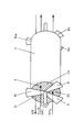
- The invention is further described in the following with reference to the drawing, in which the Figure is a perspective view of a catalyst chamber for use in the process for removal of nitrogen oxides according to one embodiment of the invention.
- The Figure shows in simplified manner catalyst chamber 1 with a honeycomb structured
denitration catalyst 2 arranged within cylindrical shell 4 of the catalyst chamber. The catalyst chamber 1 is traversed by the gases in 3 different sections,section 2a for continuous introduction of ammonia,section 2b for traversal of flue gas, andsection 2c for traversal of air countercurrently to the stream of flue gas, by sectionally sealing the faces of the catalyst chamber with sealingbaffles baffles catalyst 2 throughsections - Ammonia is continously introduced into
section 2a in parallel flow with the flue gas insection 2b and adsorbed on the catalyst surface within this section. Thereby, most of the ammonia is retarded at the inlet side of thesection 2a leading to a concentration profile of ammonia with decreasing amounts towards the outlet side of the section. Having passedsection 2a, thecatalyst 2 is rotated tosection 2b, where hot flue gas is introduced and passed through the catalyst. Nitrogen oxides contained in the flue gas are catalytically reduced with the ammonia adsorbed on the catalyst surface to molecular nitrogen and water according to the aforementioned reaction scheme. - By passage of the hot flue gas through the
catalyst 2 insection 2b, the catalyst section is heated, which heat is partly used to initiate and accomplish the catalytic reduction of nitrogen oxides. Part of the heat is after rotation further transferred to the air, which is introduced intosection 2c, countercurrently to the hot flue gas insection 2b.
Claims (6)
Applications Claiming Priority (2)
| Application Number | Priority Date | Filing Date | Title |
|---|---|---|---|
| DK183990A DK164729C (en) | 1990-08-01 | 1990-08-01 | PROCEDURE FOR CLEANING OF SMOKE AND WASTE GAS |
| DK1839/90 | 1990-08-01 |
Publications (2)
| Publication Number | Publication Date |
|---|---|
| EP0469593A1 true EP0469593A1 (en) | 1992-02-05 |
| EP0469593B1 EP0469593B1 (en) | 1995-10-04 |
Family
ID=8108449
Family Applications (1)
| Application Number | Title | Priority Date | Filing Date |
|---|---|---|---|
| EP91112913A Expired - Lifetime EP0469593B1 (en) | 1990-08-01 | 1991-07-31 | Process for the removal of nitrogen oxides from flue gases |
Country Status (5)
| Country | Link |
|---|---|
| US (1) | US5139757A (en) |
| EP (1) | EP0469593B1 (en) |
| JP (1) | JP2635861B2 (en) |
| DE (1) | DE69113559T2 (en) |
| DK (1) | DK164729C (en) |
Cited By (13)
| Publication number | Priority date | Publication date | Assignee | Title |
|---|---|---|---|---|
| EP0505882A1 (en) * | 1991-03-28 | 1992-09-30 | Siemens Aktiengesellschaft | Process and apparatus for catalytic reduction |
| WO1993000985A1 (en) * | 1991-07-02 | 1993-01-21 | General Electric Company | Supported metal oxide catalysts for the simultaneous removal of nox and sox from gas streams |
| WO1993000984A1 (en) * | 1991-07-02 | 1993-01-21 | General Electric Company | A LOW TEMPERATURE, SUPPORTED METAL OXIDE CATALYTIC NOx AND SOx REMOVAL PROCESS FOR RETROFIT TO WET FLUE GAS DESULFURIZATION SYSTEMS |
| EP0567964A2 (en) * | 1992-04-28 | 1993-11-03 | Mitsubishi Jukogyo Kabushiki Kaisha | Process for flue gas denitration |
| NL9400104A (en) * | 1993-01-23 | 1994-08-16 | Rothemuehle Brandt Kritzler | Method and device for a regenerative heat exchanger for treating waste gases containing pollutants. |
| FR2725638A1 (en) * | 1994-10-13 | 1996-04-19 | Rhone Poulenc Chimie | Novel nitrous oxide redn. catalytic compsns. |
| WO1996011740A1 (en) * | 1994-10-13 | 1996-04-25 | Rhone-Poulenc Chimie | Nitrogen oxide reducing catalyst compositions based on tantalum, vanadium, niobium, copper or antimony |
| EP0718025A1 (en) * | 1993-06-24 | 1996-06-26 | Mitsubishi Jukogyo Kabushiki Kaisha | Method for the recovery of ammonia escaping from a denitrification process |
| US5770163A (en) * | 1994-12-21 | 1998-06-23 | Mitsubishi Jukogyo Kabushiki Kaisha | System for the recovery of ammonia escaping from an ammonia reduction denitrator |
| WO2002032553A1 (en) * | 2000-10-17 | 2002-04-25 | Robert Bosch Gmbh | Exhaust gas cleaning system with a catalyst arrangement and method for cleaning exhaust gases |
| WO2004022933A1 (en) * | 2002-08-30 | 2004-03-18 | Robert Bosch Gmbh | Device for dividing gas flows |
| GB2436078A (en) * | 2006-03-18 | 2007-09-19 | Ford Global Tech Llc | An emission control device having a rotatable housing containing a catalytic brick |
| RU2494313C1 (en) * | 2012-02-28 | 2013-09-27 | Федеральное государственное бюджетное образовательное учреждение высшего профессионального образования "Юго-Западный государственный университет" (ЮЗ ГУ) | Complex regenerative rotary air heater |
Families Citing this family (9)
| Publication number | Priority date | Publication date | Assignee | Title |
|---|---|---|---|---|
| US5603909A (en) * | 1995-08-03 | 1997-02-18 | The Babcock & Wilcox Company | Selective catalytic reduction reactor integrated with condensing heat exchanger for multiple pollutant capture/removal |
| US6821490B2 (en) * | 2001-02-26 | 2004-11-23 | Abb Lummus Global Inc. | Parallel flow gas phase reactor and method for reducing the nitrogen oxide content of a gas |
| US20020159923A1 (en) * | 2001-02-26 | 2002-10-31 | Platvoet Erwin M.J. | Gas phase reactor and process for reducing nitrogen oxide in a gas stream |
| US6663839B2 (en) | 2001-02-26 | 2003-12-16 | Abb Lummus Global Inc. | Radial flow gas phase reactor and method for reducing the nitrogen oxide content of a gas |
| US6706246B2 (en) | 2001-02-26 | 2004-03-16 | Abb Lummus Global Inc. | System and method for the selective catalytic reduction of nitrogen oxide in a gas stream |
| US8659415B2 (en) | 2011-07-15 | 2014-02-25 | General Electric Company | Alarm management |
| US8751413B2 (en) | 2011-07-26 | 2014-06-10 | General Electric Company | Fuzzy logic based system monitoring system and method |
| CN103994462B (en) * | 2014-06-05 | 2016-07-27 | 山东大学 | Empty pre-denitration one reactor according and reaction method |
| CN104474895B (en) * | 2014-12-02 | 2016-06-29 | 东南大学 | The device and method of the fixing bed on-line regeneration low-temperature denitration catalyst of swinging |
Citations (2)
| Publication number | Priority date | Publication date | Assignee | Title |
|---|---|---|---|---|
| WO1987004947A1 (en) * | 1985-02-16 | 1987-08-27 | Kraftanlagen Ag | Process for the selective elimination of nitric oxides contained in exhaust gases |
| US4781902A (en) * | 1986-10-29 | 1988-11-01 | Haldor Topsoe A/S | Process for the removal of nitrogen oxides and sulphur oxides from flue gases |
Family Cites Families (3)
| Publication number | Priority date | Publication date | Assignee | Title |
|---|---|---|---|---|
| US3897539A (en) * | 1971-10-31 | 1975-07-29 | Inst Gas Technology | Tail gas nitrogen oxide abatement process |
| DE3406657A1 (en) * | 1984-02-24 | 1985-08-29 | Kraftanlagen Ag, 6900 Heidelberg | METHOD AND DEVICE FOR CATALYTICALLY PURIFYING THE EXHAUST GASES FROM COMBUSTION PLANTS |
| DE3431730A1 (en) * | 1984-08-29 | 1986-03-06 | Kraftanlagen Ag, 6900 Heidelberg | METHOD AND DEVICE FOR SELECTIVELY CATALYTICALLY REMOVING STICKOXYDES FROM THE EXHAUST GASES FROM COMBUSTION PLANTS |
-
1990
- 1990-08-01 DK DK183990A patent/DK164729C/en not_active IP Right Cessation
-
1991
- 1991-07-29 US US07/737,404 patent/US5139757A/en not_active Expired - Lifetime
- 1991-07-31 DE DE69113559T patent/DE69113559T2/en not_active Expired - Fee Related
- 1991-07-31 JP JP3191927A patent/JP2635861B2/en not_active Expired - Fee Related
- 1991-07-31 EP EP91112913A patent/EP0469593B1/en not_active Expired - Lifetime
Patent Citations (2)
| Publication number | Priority date | Publication date | Assignee | Title |
|---|---|---|---|---|
| WO1987004947A1 (en) * | 1985-02-16 | 1987-08-27 | Kraftanlagen Ag | Process for the selective elimination of nitric oxides contained in exhaust gases |
| US4781902A (en) * | 1986-10-29 | 1988-11-01 | Haldor Topsoe A/S | Process for the removal of nitrogen oxides and sulphur oxides from flue gases |
Cited By (18)
| Publication number | Priority date | Publication date | Assignee | Title |
|---|---|---|---|---|
| EP0505882A1 (en) * | 1991-03-28 | 1992-09-30 | Siemens Aktiengesellschaft | Process and apparatus for catalytic reduction |
| WO1993000985A1 (en) * | 1991-07-02 | 1993-01-21 | General Electric Company | Supported metal oxide catalysts for the simultaneous removal of nox and sox from gas streams |
| WO1993000984A1 (en) * | 1991-07-02 | 1993-01-21 | General Electric Company | A LOW TEMPERATURE, SUPPORTED METAL OXIDE CATALYTIC NOx AND SOx REMOVAL PROCESS FOR RETROFIT TO WET FLUE GAS DESULFURIZATION SYSTEMS |
| EP0567964A2 (en) * | 1992-04-28 | 1993-11-03 | Mitsubishi Jukogyo Kabushiki Kaisha | Process for flue gas denitration |
| EP0567964A3 (en) * | 1992-04-28 | 1994-03-09 | Mitsubishi Heavy Ind Ltd | |
| GB2275001B (en) * | 1993-01-23 | 1997-07-09 | Rothemuehle Brandt Kritzler | Regenerative heat exchanger |
| NL9400104A (en) * | 1993-01-23 | 1994-08-16 | Rothemuehle Brandt Kritzler | Method and device for a regenerative heat exchanger for treating waste gases containing pollutants. |
| GB2275001A (en) * | 1993-01-23 | 1994-08-17 | Rothemuehle Brandt Kritzler | Regenerative heat exchanger |
| US5678625A (en) * | 1993-01-23 | 1997-10-21 | Apparatebau Rothemuhle Brandt & Kritzler Gmbh | Method and apparatus for a regenerative heat exchanger for the treatment of pollutant-containing waste gases |
| EP0718025A1 (en) * | 1993-06-24 | 1996-06-26 | Mitsubishi Jukogyo Kabushiki Kaisha | Method for the recovery of ammonia escaping from a denitrification process |
| WO1996011740A1 (en) * | 1994-10-13 | 1996-04-25 | Rhone-Poulenc Chimie | Nitrogen oxide reducing catalyst compositions based on tantalum, vanadium, niobium, copper or antimony |
| FR2725638A1 (en) * | 1994-10-13 | 1996-04-19 | Rhone Poulenc Chimie | Novel nitrous oxide redn. catalytic compsns. |
| US5770163A (en) * | 1994-12-21 | 1998-06-23 | Mitsubishi Jukogyo Kabushiki Kaisha | System for the recovery of ammonia escaping from an ammonia reduction denitrator |
| WO2002032553A1 (en) * | 2000-10-17 | 2002-04-25 | Robert Bosch Gmbh | Exhaust gas cleaning system with a catalyst arrangement and method for cleaning exhaust gases |
| WO2004022933A1 (en) * | 2002-08-30 | 2004-03-18 | Robert Bosch Gmbh | Device for dividing gas flows |
| GB2436078A (en) * | 2006-03-18 | 2007-09-19 | Ford Global Tech Llc | An emission control device having a rotatable housing containing a catalytic brick |
| GB2436078B (en) * | 2006-03-18 | 2009-08-05 | Ford Global Tech Llc | An emission control device for an engine |
| RU2494313C1 (en) * | 2012-02-28 | 2013-09-27 | Федеральное государственное бюджетное образовательное учреждение высшего профессионального образования "Юго-Западный государственный университет" (ЮЗ ГУ) | Complex regenerative rotary air heater |
Also Published As
| Publication number | Publication date |
|---|---|
| DK164729C (en) | 1992-12-28 |
| DE69113559T2 (en) | 1996-03-07 |
| DK183990A (en) | 1992-02-02 |
| DK183990D0 (en) | 1990-08-01 |
| DK164729B (en) | 1992-08-10 |
| JPH04227026A (en) | 1992-08-17 |
| DE69113559D1 (en) | 1995-11-09 |
| JP2635861B2 (en) | 1997-07-30 |
| US5139757A (en) | 1992-08-18 |
| EP0469593B1 (en) | 1995-10-04 |
Similar Documents
| Publication | Publication Date | Title |
|---|---|---|
| EP0469593A1 (en) | Process for the removal of nitrogen oxides from flue gases | |
| US4912776A (en) | Process for removal of NOx from fluid streams | |
| US3544264A (en) | Method and means for two-stage catalytic treating of engine exhaust gases | |
| EP0801978B1 (en) | Process for the denitration of exhaust gases with heat treated activated carbon | |
| CA2193638C (en) | Exhaust gas treating systems | |
| US6207116B1 (en) | Catalytic purification device | |
| JPH0714457B2 (en) | Method for purifying waste gas containing nitrogen and sulfur oxides from a combustion device | |
| UA48162C2 (en) | METHOD OF SULFUR COMBINATION H<sub>2S, SO</sub><sub>2, COS AND/OR CS</sub><sub>2 REMOVAL FROM THE SULFUR SET EXHAUST GAS | |
| US4867953A (en) | Method for the selective elimination of nitrogen oxides from exhaust gases | |
| EP0516001B1 (en) | Process for the regeneration of spent sulphuric acid | |
| JP4435417B2 (en) | Pollution control equipment | |
| US4781902A (en) | Process for the removal of nitrogen oxides and sulphur oxides from flue gases | |
| JPH0622655B2 (en) | Method and apparatus for catalytically selective removal of nitric oxide from combustor waste gas | |
| US5401479A (en) | Process for the removal of nitrogen oxides from off-gases | |
| US6814948B1 (en) | Exhaust gas treating systems | |
| JP2004530537A (en) | Apparatus system and method for selective catalytic reduction of nitrogen oxides in gas streams | |
| CA2196196C (en) | Catalytic purification device | |
| CA2391710C (en) | Method and device for catalytically treating exhaust gas containing dust and oxygen | |
| US4842843A (en) | Removal of water vapor diluent after regeneration of metal oxide absorbent to reduce recycle stream | |
| US20030157007A1 (en) | Method and device for the catalytically treating exhaust gas containing dust and oxygen | |
| CA1047224A (en) | Hydrogen cyanide destruction | |
| AU718019B2 (en) | Exhaust gas treatment process | |
| PL126861B1 (en) | Method of catalytically purifying gases | |
| JPH0154089B2 (en) | ||
| US20030133849A1 (en) | Amonia oxidaion with reduced formation of N2O |
Legal Events
| Date | Code | Title | Description |
|---|---|---|---|
| PUAI | Public reference made under article 153(3) epc to a published international application that has entered the european phase |
Free format text: ORIGINAL CODE: 0009012 |
|
| AK | Designated contracting states |
Kind code of ref document: A1 Designated state(s): DE DK FR GB IT SE |
|
| 17P | Request for examination filed |
Effective date: 19920629 |
|
| 17Q | First examination report despatched |
Effective date: 19930810 |
|
| GRAA | (expected) grant |
Free format text: ORIGINAL CODE: 0009210 |
|
| AK | Designated contracting states |
Kind code of ref document: B1 Designated state(s): DE DK FR GB IT SE |
|
| PG25 | Lapsed in a contracting state [announced via postgrant information from national office to epo] |
Ref country code: DK Effective date: 19951004 |
|
| ITF | It: translation for a ep patent filed |
Owner name: BUGNION S.P.A. |
|
| REF | Corresponds to: |
Ref document number: 69113559 Country of ref document: DE Date of ref document: 19951109 |
|
| ET | Fr: translation filed | ||
| PLBE | No opposition filed within time limit |
Free format text: ORIGINAL CODE: 0009261 |
|
| STAA | Information on the status of an ep patent application or granted ep patent |
Free format text: STATUS: NO OPPOSITION FILED WITHIN TIME LIMIT |
|
| 26N | No opposition filed | ||
| REG | Reference to a national code |
Ref country code: GB Ref legal event code: IF02 |
|
| PGFP | Annual fee paid to national office [announced via postgrant information from national office to epo] |
Ref country code: DE Payment date: 20080829 Year of fee payment: 18 |
|
| PGFP | Annual fee paid to national office [announced via postgrant information from national office to epo] |
Ref country code: IT Payment date: 20080728 Year of fee payment: 18 Ref country code: FR Payment date: 20080729 Year of fee payment: 18 |
|
| PGFP | Annual fee paid to national office [announced via postgrant information from national office to epo] |
Ref country code: GB Payment date: 20080729 Year of fee payment: 18 |
|
| PGFP | Annual fee paid to national office [announced via postgrant information from national office to epo] |
Ref country code: SE Payment date: 20080729 Year of fee payment: 18 |
|
| GBPC | Gb: european patent ceased through non-payment of renewal fee |
Effective date: 20090731 |
|
| REG | Reference to a national code |
Ref country code: FR Ref legal event code: ST Effective date: 20100331 |
|
| PG25 | Lapsed in a contracting state [announced via postgrant information from national office to epo] |
Ref country code: FR Free format text: LAPSE BECAUSE OF NON-PAYMENT OF DUE FEES Effective date: 20090731 |
|
| PG25 | Lapsed in a contracting state [announced via postgrant information from national office to epo] |
Ref country code: GB Free format text: LAPSE BECAUSE OF NON-PAYMENT OF DUE FEES Effective date: 20090731 |
|
| PG25 | Lapsed in a contracting state [announced via postgrant information from national office to epo] |
Ref country code: DE Free format text: LAPSE BECAUSE OF NON-PAYMENT OF DUE FEES Effective date: 20100202 |
|
| PG25 | Lapsed in a contracting state [announced via postgrant information from national office to epo] |
Ref country code: IT Free format text: LAPSE BECAUSE OF NON-PAYMENT OF DUE FEES Effective date: 20090731 |
|
| PG25 | Lapsed in a contracting state [announced via postgrant information from national office to epo] |
Ref country code: SE Free format text: LAPSE BECAUSE OF NON-PAYMENT OF DUE FEES Effective date: 20090801 |