EP0469360A2 - Method and apparatus for the wet separation of heterogeneous mixtures containing solids having different densities - Google Patents
Method and apparatus for the wet separation of heterogeneous mixtures containing solids having different densities Download PDFInfo
- Publication number
- EP0469360A2 EP0469360A2 EP91111589A EP91111589A EP0469360A2 EP 0469360 A2 EP0469360 A2 EP 0469360A2 EP 91111589 A EP91111589 A EP 91111589A EP 91111589 A EP91111589 A EP 91111589A EP 0469360 A2 EP0469360 A2 EP 0469360A2
- Authority
- EP
- European Patent Office
- Prior art keywords
- tank
- discrimination
- fractions
- water
- chamber
- Prior art date
- Legal status (The legal status is an assumption and is not a legal conclusion. Google has not performed a legal analysis and makes no representation as to the accuracy of the status listed.)
- Granted
Links
Images

Classifications
-
- B—PERFORMING OPERATIONS; TRANSPORTING
- B03—SEPARATION OF SOLID MATERIALS USING LIQUIDS OR USING PNEUMATIC TABLES OR JIGS; MAGNETIC OR ELECTROSTATIC SEPARATION OF SOLID MATERIALS FROM SOLID MATERIALS OR FLUIDS; SEPARATION BY HIGH-VOLTAGE ELECTRIC FIELDS
- B03B—SEPARATING SOLID MATERIALS USING LIQUIDS OR USING PNEUMATIC TABLES OR JIGS
- B03B5/00—Washing granular, powdered or lumpy materials; Wet separating
- B03B5/28—Washing granular, powdered or lumpy materials; Wet separating by sink-float separation
- B03B5/30—Washing granular, powdered or lumpy materials; Wet separating by sink-float separation using heavy liquids or suspensions
- B03B5/32—Washing granular, powdered or lumpy materials; Wet separating by sink-float separation using heavy liquids or suspensions using centrifugal force
-
- B—PERFORMING OPERATIONS; TRANSPORTING
- B03—SEPARATION OF SOLID MATERIALS USING LIQUIDS OR USING PNEUMATIC TABLES OR JIGS; MAGNETIC OR ELECTROSTATIC SEPARATION OF SOLID MATERIALS FROM SOLID MATERIALS OR FLUIDS; SEPARATION BY HIGH-VOLTAGE ELECTRIC FIELDS
- B03B—SEPARATING SOLID MATERIALS USING LIQUIDS OR USING PNEUMATIC TABLES OR JIGS
- B03B5/00—Washing granular, powdered or lumpy materials; Wet separating
- B03B5/28—Washing granular, powdered or lumpy materials; Wet separating by sink-float separation
-
- B—PERFORMING OPERATIONS; TRANSPORTING
- B03—SEPARATION OF SOLID MATERIALS USING LIQUIDS OR USING PNEUMATIC TABLES OR JIGS; MAGNETIC OR ELECTROSTATIC SEPARATION OF SOLID MATERIALS FROM SOLID MATERIALS OR FLUIDS; SEPARATION BY HIGH-VOLTAGE ELECTRIC FIELDS
- B03B—SEPARATING SOLID MATERIALS USING LIQUIDS OR USING PNEUMATIC TABLES OR JIGS
- B03B5/00—Washing granular, powdered or lumpy materials; Wet separating
- B03B5/62—Washing granular, powdered or lumpy materials; Wet separating by hydraulic classifiers, e.g. of launder, tank, spiral or helical chute concentrator type
- B03B5/623—Upward current classifiers
Definitions
- This invention covers the implementation of a system, preferentially but not exclusively devised for discrimination of solid fractions having differentiated density in heterogeneous mixtures using water as a fluid and in particular for descrimination of putrescible organic fractions of solid urban waste to be converted into compost or used for biogas production.
- This invention will make it possible almost completely to separate the heavy components in the raw organic fraction (glass, fragments of pottery, stones, metal, rigid plastic material, cells and heavy inert matter of any kind) from the lighter fractions (paper, organic matter etc.)
- Water too may permit - within well defined limits - sink-float operations to separate materials having a higher than 1 density from those whose density is less than 1, i.e. having a lower density than water.
- This invention has the aim to make it possible to take advantage of gravitational separation in water since this method is most economic because of its low operating cost.
- This aim is achieved by combining two effects: i.e. gravitational separation and the generation of water streams having differentiated entrainment capacity thus inviting irresolute fractions to follow given routes and hence promoting the desired discrimination.
- the invention provides for a cylindrical discrimination chamber having a truncated cone shaped bottom, placed inside an external settling basin filled with water.
- These two settling and discrimination tanks have an open bottom.
- the system is completed by a screw distributor located in the lower part of the discrimination tank and a propelling impeller mounted below the dispersion tank just above the distributor, in order to generate adequate current flows to complete the required sorting.
- the separator is essentially consisting of four assemblies which will be described hereinafter.
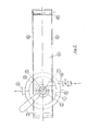
- the first assembly is consisting of a cyclin- drical discrimination tank 1 with truncated cone-shaped bottom which is kept constantly filled with water, surrounding and supporting - by means of four tie rods 32 - the coaxial dispersion chamber 2 which is completely immersed in the liquid and in which the mixture to be processed is fed through the channel 3 together with most of the process water .
- the discrimination tank 1 has an overflow 4 through which excess water is discharged together with any supernatant fractions of the mixture which are collected in the ring-shaped effluent channel 5 and are drained through the outlet 6 connected to the channel 5.
- the lower orifice 7 of the discrimination tank is hydraulically closed.
- the heavy inert fractions such as glass, stones, metals, cells etc. are discharged through this orifice and are then mechanically removed as will be explained hereinafter.
- a "spiral chamber" for distribution of the make-up water 8 is located outside the terminal cone of the discrimination tank, immediately above the orifice 7; this spiral chamber lets the water into the tank 1 by means of the guide vanes 9 conveying the water entering the tube 10, in the correct flow direction of the fluid .
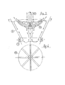
- the second assembly is consisting of a propelling unit located inside the discrimination tank 1 along its central vertical axis XX; this propeller is essentially consisting of a geared motor 11, a shaft coinciding with the XX axis and an impeller 13 forged into the shape of an upside-down "chinese hat” fitted with upper and lower radial vanes (fig.3).
- the "propeller” assembly is completed by a base supporting the geared motor unit and a flexible coupling 15 connecting the driving unit to the impeller shaft.
- the latter is supported by two water lubricated bushes 16 and 17 mounted at the upper and lower end of the casing 18 resting on the flange 19 with the fitting 20 through which pressurized clean water can be let into the casing 18 for lubrication of the bushes 16 and 17.
- the impeller is located below the lower orifice of the dispersion chamber 2 and above the row of guide vanes 9 of the spiral chamber 8 as illustrated in fig.1.
- the third assembly is consisting of a settling basin 21 surrounding the discrimination tank 1 and extending above the upper level of the fluid overflowing from the spillway 4 of the discrimination chamber 1.
- the settling basin 21 has two vertical and parallel sides 22 and 23, separated by a third polygonal traverse wall 24 at right angles to the walls 22 and 23 so as to form the bottom of the sattling basin 21.
- Fig. 1 clearly shows that the polygonal wall 24 is consisting of an initial section a, followed by a sub-vertical section b, a horizontal section c and a final section d gently sloping upwards and extending well beyond the free surface of the liquid.
- the section d of the polygonal wall 24 has an opening with a discharge nozzle 25 at its upper end, well above the liquid surface.
- the settling basin 21 is communicating with the discrimination tank 1 by means of an orifice 7. Basin 21 and tank 1 are both filled with water and will have the same free surface level e I according to the principle of communicating vessels.
- the fourth assembly is consisting of a chain scraper 27 having the task to collect the heavy inert fractions, discharged through the lower orifice 7 of the discrimination tank 1 into the settling basin 21 where they settle on the bottom of the basin.
- the chain scraper 27 is fitted with scraper blades 28 slowly grazing the bottom and dredging the deposited material, dragging it along the section d of the bottom wall 24 of the basin, so that it can be discharged, after a short drying length, above the water surface, through the outlet 25.
- the chain scraper 27 is supported by a guide pulley 29 and supporting roller 30.
- the chain is driven by a properly recessed or toothed driving roller 31, driven by a geared motor so that it will be possible to adjust the scraper speed within a large range and hence to vary its transport and discharge capacity.
- the separator subject matter of this invention is operating as described hereinafter. To obtain acceptable results and yields it is obviously necessary to provide for extreme dispersion of the mixture to be sorted out so that each elementary item in the dispersed mixture has a sufficient degree of freedom.
- Dispersions with a 3% to 8% content of dry solid matter are usually adopted.
- the mixture to be separated is introduced through the channel 3 where a fair amount of water is also added.
- the heterogenous suspension is let into the dispersion chamber 2 in which downward circulating water is whirling under the helical action of the bladed impeller 13 having the shape of an upside-down "chinese hat".
- the mixture is dispersed during its downward motion towards the impeller and even water-repellent items which tend to float are entering the liquid whirlpool and entrained downwards.
- the dispersed mixture thus obtained is hurled outwards where the lighter and floating fractions (vegetables, paper and organic matter) will reascend in a spiral motion along the wall of the discrimination tank 1 until they reach the water surface where part of it will flow over the edge 4 to be discharged through the drain channel 5 whereas another part will be drawn back to the center of the dispersion chamber 2 to start another cycle together with the material coming from the channel 3.
- the lighter solid fractions or those having a larger wetted surface with respect to their volume will be entrained upwards in a spiral motion toward the water surface, whereas the heavier fractions such as inert materials, metals etc. will move downwards following the same helical motion.
- the more or less fast downward movement will bring these heavy fractions below the YY center-line of the impeller 13 where they will be entrained by a secondary whirlpool and hurled outwards and then thrust axially upwards under the action of the radial blades mounted on the lower surface of the impeller 13.
- the discriminant action leading to complete release and separation of inert solids from the remaining components of the mixture is thus completed in this cone-shaped terminal section of the tank 1.
- fractions having a density of approximately 1 will also be entrained during the downward spiral movement and will zeroize their centrifugal component when impinging on the cone wall so that they will be conveyed downward together with the heavier material.
- the ideal trajectory will convey this mixture of inert and organic matter in front of the blading 9 through which a certain amount of clean (or recycled) make-up water will be let in the same direction of the spiral flow inside the cone.
- This strean will ensure that less heavy particles will be directed towards the cone axis where they will be caught by the axial flow towards the impeller and recycled towards the periphery of the YY section.
- the reascending water stream due to the water entering the blading 9, will convey the organic particles back to the upper portion of the YY section so that they will recirculate in the main stream towards the upper edge 4 of the tank where the water and the floating fractions will be discharged into the ring-shaped channel 5 and drained through the outlet 6, as already explained above.
- the heavier materials, rigid plastics, sand, glass, fragments of pottery, metal and the like will pass the threshold 7 of the discharge orifice of the cone in a slight counter-current flow of the water entering the settling basin 21 through the feed-cock 26, then flowing upwards through the threshold 7 into the discrimination tank 1, to be discharged into the anular channel 5 together with the purified material and drained through the outlet 6.
Abstract
Description
- This invention covers the implementation of a system, preferentially but not exclusively devised for discrimination of solid fractions having differentiated density in heterogeneous mixtures using water as a fluid and in particular for descrimination of putrescible organic fractions of solid urban waste to be converted into compost or used for biogas production.
- This invention will make it possible almost completely to separate the heavy components in the raw organic fraction (glass, fragments of pottery, stones, metal, rigid plastic material, cells and heavy inert matter of any kind) from the lighter fractions (paper, organic matter etc.)
- To separate a heterogeneous mixture of solids having different density values into two (or even more than two) fractions, known - so called "sink-float" systems - may be used based upon usually dense liquids in which some solids may float while others will sink to the bottom.
- Water too may permit - within well defined limits - sink-float operations to separate materials having a higher than 1 density from those whose density is less than 1, i.e. having a lower density than water.
- There is, however, a large quantity of solid waste components , such as vegetables, some legumes, fruit, paper, organic tissue , just to list a few and many others which may either float or sink with some difficulty (as for instance a leaf of lattuce or onion or paper); they often remain floating midway in the water. A slight current is enough to keep them floating or entrain them without remaining at the surface or sinking down to the bottom.
- This means that the systems hitherto known for gravitational "sink-float" separation in water have yielded no practical results, especially for solid urban waste discrimination and can therefore not be used.
- This invention has the aim to make it possible to take advantage of gravitational separation in water since this method is most economic because of its low operating cost.
- This aim is achieved by combining two effects: i.e. gravitational separation and the generation of water streams having differentiated entrainment capacity thus inviting irresolute fractions to follow given routes and hence promoting the desired discrimination.
- For this purpose, the invention provides for a cylindrical discrimination chamber having a truncated cone shaped bottom, placed inside an external settling basin filled with water.
- Furthermore, an also cylinder-shaped dispersion chamber with truncated-cone bottom fed with the mixture to be treated, is coaxially placed in the discrimination tank . These two settling and discrimination tanks have an open bottom.
- The system is completed by a screw distributor located in the lower part of the discrimination tank and a propelling impeller mounted below the dispersion tank just above the distributor, in order to generate adequate current flows to complete the required sorting.
- The invention in question is illustrated in its preferable implementation in the enclosed drawings in which:
- fig.1 shows a lengthwise vertical section of the separator in question;
- Fig.2 shows a top view of the separator illustrated in fig.1;
- Fig.3 shows the central vertical section of the propelling unit.
- Fig.4 shows a top view of the propeller illustrated in fig.3.
- With reference to these figures, the separator is essentially consisting of four assemblies which will be described hereinafter.
- The first assembly is consisting of a cyclin-
drical discrimination tank 1 with truncated cone-shaped bottom which is kept constantly filled with water, surrounding and supporting - by means of four tie rods 32 - the coaxial dispersion chamber 2 which is completely immersed in the liquid and in which the mixture to be processed is fed through thechannel 3 together with most of the process water . Thediscrimination tank 1 has anoverflow 4 through which excess water is discharged together with any supernatant fractions of the mixture which are collected in the ring-shaped effluent channel 5 and are drained through theoutlet 6 connected to thechannel 5. The lower orifice 7 of the discrimination tank is hydraulically closed. - The heavy inert fractions such as glass, stones, metals, cells etc. are discharged through this orifice and are then mechanically removed as will be explained hereinafter.
- A "spiral chamber" for distribution of the make-
up water 8 is located outside the terminal cone of the discrimination tank, immediately above the orifice 7; this spiral chamber lets the water into thetank 1 by means of theguide vanes 9 conveying the water entering thetube 10, in the correct flow direction of the fluid . - The second assembly is consisting of a propelling unit located inside the
discrimination tank 1 along its central vertical axis XX; this propeller is essentially consisting of a geared motor 11, a shaft coinciding with the XX axis and animpeller 13 forged into the shape of an upside-down "chinese hat" fitted with upper and lower radial vanes (fig.3). The "propeller" assembly is completed by a base supporting the geared motor unit and a flexible coupling 15 connecting the driving unit to the impeller shaft. The latter is supported by two water lubricatedbushes casing 18 resting on theflange 19 with the fitting 20 through which pressurized clean water can be let into thecasing 18 for lubrication of thebushes guide vanes 9 of thespiral chamber 8 as illustrated in fig.1. - The third assembly is consisting of a
settling basin 21 surrounding thediscrimination tank 1 and extending above the upper level of the fluid overflowing from thespillway 4 of thediscrimination chamber 1. - The
settling basin 21 has two vertical andparallel sides polygonal traverse wall 24 at right angles to thewalls sattling basin 21. - Fig. 1 clearly shows that the
polygonal wall 24 is consisting of an initial section a, followed by a sub-vertical section b, a horizontal section c and a final section d gently sloping upwards and extending well beyond the free surface of the liquid. - The section d of the
polygonal wall 24 has an opening with adischarge nozzle 25 at its upper end, well above the liquid surface. - The settling
basin 21 is communicating with thediscrimination tank 1 by means of an orifice 7.Basin 21 andtank 1 are both filled with water and will have the same free surface level e I according to the principle of communicating vessels. - Therefore, no water should flow through the orifice 7. Actually, there will be a slight upward flow due to clean make-up water entering through the
feed cokck 25 which, among others, will make up for any imbibition losses caused by the heavy inert and polluting material discharged through theoutlet 25. - From fig. 1, it can be observed that the discrimination and
dispersion tanks 1 and 2 have their XX axis in the maximum vertical dimension zone of thesettling basin 21. - The fourth assembly is consisting of a
chain scraper 27 having the task to collect the heavy inert fractions, discharged through the lower orifice 7 of thediscrimination tank 1 into thesettling basin 21 where they settle on the bottom of the basin. - The
chain scraper 27 is fitted withscraper blades 28 slowly grazing the bottom and dredging the deposited material, dragging it along the section d of thebottom wall 24 of the basin, so that it can be discharged, after a short drying length, above the water surface, through theoutlet 25. - Outside the settling basin, the
chain scraper 27 is supported by aguide pulley 29 and supportingroller 30. The chain is driven by a properly recessed or toothed driving roller 31, driven by a geared motor so that it will be possible to adjust the scraper speed within a large range and hence to vary its transport and discharge capacity. - Based upon the foregoing, the separator subject matter of this invention is operating as described hereinafter. To obtain acceptable results and yields it is obviously necessary to provide for extreme dispersion of the mixture to be sorted out so that each elementary item in the dispersed mixture has a sufficient degree of freedom.
- Dispersions with a 3% to 8% content of dry solid matter are usually adopted. The mixture to be separated is introduced through the
channel 3 where a fair amount of water is also added. The heterogenous suspension is let into the dispersion chamber 2 in which downward circulating water is whirling under the helical action of thebladed impeller 13 having the shape of an upside-down "chinese hat". - The mixture is dispersed during its downward motion towards the impeller and even water-repellent items which tend to float are entering the liquid whirlpool and entrained downwards. The dispersed mixture thus obtained is hurled outwards where the lighter and floating fractions (vegetables, paper and organic matter) will reascend in a spiral motion along the wall of the
discrimination tank 1 until they reach the water surface where part of it will flow over theedge 4 to be discharged through thedrain channel 5 whereas another part will be drawn back to the center of the dispersion chamber 2 to start another cycle together with the material coming from thechannel 3. - Heavy fine solid matter will be centrifuged beyond the fluid threads which can be ideally identified in the water flow and these fines will impinge on the fixed wall of the
discrimination tank 1. When impinging on the wall, their speed is checked or at least greatly reduced so that the gravity action and the differential downward thrust will prevail. - Thus, the lighter solid fractions or those having a larger wetted surface with respect to their volume will be entrained upwards in a spiral motion toward the water surface, whereas the heavier fractions such as inert materials, metals etc. will move downwards following the same helical motion. The more or less fast downward movement will bring these heavy fractions below the YY center-line of the
impeller 13 where they will be entrained by a secondary whirlpool and hurled outwards and then thrust axially upwards under the action of the radial blades mounted on the lower surface of theimpeller 13. The discriminant action leading to complete release and separation of inert solids from the remaining components of the mixture is thus completed in this cone-shaped terminal section of thetank 1. - Inevitably, some fractions having a density of approximately 1 will also be entrained during the downward spiral movement and will zeroize their centrifugal component when impinging on the cone wall so that they will be conveyed downward together with the heavier material.
- At a given point during their sinking, the ideal trajectory will convey this mixture of inert and organic matter in front of the
blading 9 through which a certain amount of clean (or recycled) make-up water will be let in the same direction of the spiral flow inside the cone. - This strean will ensure that less heavy particles will be directed towards the cone axis where they will be caught by the axial flow towards the impeller and recycled towards the periphery of the YY section.
- The reascending water stream, due to the water entering the
blading 9, will convey the organic particles back to the upper portion of the YY section so that they will recirculate in the main stream towards theupper edge 4 of the tank where the water and the floating fractions will be discharged into the ring-shaped channel 5 and drained through theoutlet 6, as already explained above. - The heavier materials, rigid plastics, sand, glass, fragments of pottery, metal and the like will pass the threshold 7 of the discharge orifice of the cone in a slight counter-current flow of the water entering the
settling basin 21 through the feed-cock 26, then flowing upwards through the threshold 7 into thediscrimination tank 1, to be discharged into theanular channel 5 together with the purified material and drained through theoutlet 6. - Heavy and polluting fractions entering the
settling tank 21 where the water is virtually calm, will sink to thebottom 24 of thetank 21. They will be scooped by thechain scraper 27 gently grazing thebottom wall 24 of thesettling tank 21 and lifted along the sloping wall section d until they are raised above the liquid surface "1" and, after partial dewatering, are discharged through theoutlet 25.
Claims (5)
so that the components of the heterogeneous mixture can be separated either by gravity or under the action of proper whirlpools generated by the impeller and by the spiral chamber
Priority Applications (1)
| Application Number | Priority Date | Filing Date | Title |
|---|---|---|---|
| AT91111589T ATE100734T1 (en) | 1990-08-02 | 1991-07-12 | METHOD AND DEVICE FOR WET SEPARATION OF HETEROGENOUS MIXTURES OF SOLIDS OF DIFFERENT DENSITY. |
Applications Claiming Priority (2)
| Application Number | Priority Date | Filing Date | Title |
|---|---|---|---|
| IT12501A IT1241887B (en) | 1990-08-02 | 1990-08-02 | WET SEPARATOR FOR DISCRIMINATION IN AT LEAST TWO FRACTIONS OF HETEROGENEOUS MIXTURES OF BODIES OF DIFFERENT DENSITIES DISPERSED IN A FLUID AND PARTICULARLY IN WATER |
| IT1250190 | 1990-08-02 |
Publications (3)
| Publication Number | Publication Date |
|---|---|
| EP0469360A2 true EP0469360A2 (en) | 1992-02-05 |
| EP0469360A3 EP0469360A3 (en) | 1992-03-18 |
| EP0469360B1 EP0469360B1 (en) | 1994-01-26 |
Family
ID=11140909
Family Applications (1)
| Application Number | Title | Priority Date | Filing Date |
|---|---|---|---|
| EP91111589A Expired - Lifetime EP0469360B1 (en) | 1990-08-02 | 1991-07-12 | Method and apparatus for the wet separation of heterogeneous mixtures containing solids having different densities |
Country Status (4)
| Country | Link |
|---|---|
| EP (1) | EP0469360B1 (en) |
| AT (1) | ATE100734T1 (en) |
| DE (1) | DE69101092D1 (en) |
| IT (1) | IT1241887B (en) |
Cited By (4)
| Publication number | Priority date | Publication date | Assignee | Title |
|---|---|---|---|---|
| EP1002563A1 (en) * | 1998-11-17 | 2000-05-24 | FirstEnergy Ventures | Method and apparatus for separating fast settling particles from slow settling particles |
| EP1516672A1 (en) * | 2003-09-22 | 2005-03-23 | Hans Huber AG Maschinen- und Anlagenbau | Apparatus for separating of organic from inorganic material |
| JP2012196612A (en) * | 2011-03-18 | 2012-10-18 | Mitsubishi Electric Corp | Sorter of specific gravity |
| CN103008092A (en) * | 2012-12-27 | 2013-04-03 | 曾广洛 | Mineral separator and use method thereof |
Citations (4)
| Publication number | Priority date | Publication date | Assignee | Title |
|---|---|---|---|---|
| US1996547A (en) * | 1933-05-27 | 1935-04-02 | And Continental Illinois Bank | Separator and method |
| GB962386A (en) * | 1963-04-08 | 1964-07-01 | Insinooritoimisto Engineeringb | An improved hydraulic classifier |
| DE1216211B (en) * | 1966-05-12 | Insinööritoimisto-Engmeering Bureau R. T. Hukki, Otaniemi (Finnland) | Method and device for the continuous classification and / or sorting of solids | |
| US4416764A (en) * | 1980-11-28 | 1983-11-22 | Natomas Energy Company | Method and appratus for extracting tar sand |
-
1990
- 1990-08-02 IT IT12501A patent/IT1241887B/en active IP Right Grant
-
1991
- 1991-07-12 DE DE91111589T patent/DE69101092D1/en not_active Expired - Lifetime
- 1991-07-12 EP EP91111589A patent/EP0469360B1/en not_active Expired - Lifetime
- 1991-07-12 AT AT91111589T patent/ATE100734T1/en not_active IP Right Cessation
Patent Citations (4)
| Publication number | Priority date | Publication date | Assignee | Title |
|---|---|---|---|---|
| DE1216211B (en) * | 1966-05-12 | Insinööritoimisto-Engmeering Bureau R. T. Hukki, Otaniemi (Finnland) | Method and device for the continuous classification and / or sorting of solids | |
| US1996547A (en) * | 1933-05-27 | 1935-04-02 | And Continental Illinois Bank | Separator and method |
| GB962386A (en) * | 1963-04-08 | 1964-07-01 | Insinooritoimisto Engineeringb | An improved hydraulic classifier |
| US4416764A (en) * | 1980-11-28 | 1983-11-22 | Natomas Energy Company | Method and appratus for extracting tar sand |
Cited By (7)
| Publication number | Priority date | Publication date | Assignee | Title |
|---|---|---|---|---|
| EP1002563A1 (en) * | 1998-11-17 | 2000-05-24 | FirstEnergy Ventures | Method and apparatus for separating fast settling particles from slow settling particles |
| US6250473B1 (en) | 1998-11-17 | 2001-06-26 | Firstenergy Ventures Corp. | Method and apparatus for separating fast settling particles from slow settling particles |
| EP1516672A1 (en) * | 2003-09-22 | 2005-03-23 | Hans Huber AG Maschinen- und Anlagenbau | Apparatus for separating of organic from inorganic material |
| US7318527B2 (en) | 2003-09-22 | 2008-01-15 | Hans Huber Ag Maschinen-Und Anlagenbau | Apparatus for separating organic material from inorganic material |
| JP2012196612A (en) * | 2011-03-18 | 2012-10-18 | Mitsubishi Electric Corp | Sorter of specific gravity |
| CN103008092A (en) * | 2012-12-27 | 2013-04-03 | 曾广洛 | Mineral separator and use method thereof |
| CN103008092B (en) * | 2012-12-27 | 2014-12-10 | 曾广洛 | Mineral separator and use method thereof |
Also Published As
| Publication number | Publication date |
|---|---|
| ATE100734T1 (en) | 1994-02-15 |
| DE69101092D1 (en) | 1994-03-10 |
| EP0469360A3 (en) | 1992-03-18 |
| IT9012501A0 (en) | 1990-08-02 |
| IT1241887B (en) | 1994-02-01 |
| IT9012501A1 (en) | 1992-02-02 |
| EP0469360B1 (en) | 1994-01-26 |
Similar Documents
| Publication | Publication Date | Title |
|---|---|---|
| CA1191042A (en) | Method and apparatus for recovering paper-making fiber from contaminated waste paper products | |
| US5641397A (en) | Device for separating inorganic material polluted by organic material from a fluid | |
| US4999115A (en) | Method and apparatus for use in separating solids from liquids | |
| US6988622B1 (en) | Venturi-driven flotation separator for chili peppers | |
| KR101729262B1 (en) | Adulteration disposal equipment with wedge bar screen | |
| US4436617A (en) | Froth flotation ore beneficiation process utilizing enhanced gasification and flow techniques | |
| CN104069954B (en) | A kind of Coal Flotation Column Process and method for sorting high-concentration ore slurry | |
| US20140190897A1 (en) | Enhanced separation of nuisance materials from wastewater | |
| EP0006867A1 (en) | Apparatus and process for ordinary and submarine mineral beneficiation | |
| JP5317887B2 (en) | Cleaning device | |
| US4532034A (en) | Continuously operating separating apparatus for the separation of mixtures of light and heavy liquid components | |
| US3705650A (en) | Vacuum flotation device | |
| US5564574A (en) | Mineral separator | |
| US10065197B2 (en) | Hydraulic particle separation apparatus for placer mining | |
| EP0469360B1 (en) | Method and apparatus for the wet separation of heterogeneous mixtures containing solids having different densities | |
| SU1755704A3 (en) | Plant for preparation of pond-flotation coal slime | |
| US7468136B2 (en) | Grit trap | |
| CN108330719B (en) | Device for removing impurities from rotary drum pulper | |
| JP3457619B2 (en) | Mixed plastic separation method and apparatus | |
| KR20020066326A (en) | Centrifugal separator | |
| SU1417789A3 (en) | Apparatus for separating various components of product in heavy suspension | |
| US2978100A (en) | Method of and apparatus for concentrating and separating ore | |
| JPH01292296A (en) | Separator-extractor of radioactive waste water mixture | |
| US8506824B1 (en) | Method for separating putrescible organic matter from inorganic grit suspended in waste water and sewage | |
| SU1512474A3 (en) | Single-separation separator of heavy suspension |
Legal Events
| Date | Code | Title | Description |
|---|---|---|---|
| PUAI | Public reference made under article 153(3) epc to a published international application that has entered the european phase |
Free format text: ORIGINAL CODE: 0009012 |
|
| PUAL | Search report despatched |
Free format text: ORIGINAL CODE: 0009013 |
|
| AK | Designated contracting states |
Kind code of ref document: A2 Designated state(s): AT BE CH DE DK ES FR GB GR LI LU NL SE |
|
| AK | Designated contracting states |
Kind code of ref document: A3 Designated state(s): AT BE CH DE DK ES FR GB GR LI LU NL SE |
|
| 17P | Request for examination filed |
Effective date: 19920421 |
|
| 17Q | First examination report despatched |
Effective date: 19930312 |
|
| GRAA | (expected) grant |
Free format text: ORIGINAL CODE: 0009210 |
|
| AK | Designated contracting states |
Kind code of ref document: B1 Designated state(s): AT BE CH DE DK ES FR GB GR LI LU NL SE |
|
| PG25 | Lapsed in a contracting state [announced via postgrant information from national office to epo] |
Ref country code: SE Effective date: 19940126 Ref country code: NL Effective date: 19940126 Ref country code: LI Effective date: 19940126 Ref country code: GR Free format text: LAPSE BECAUSE OF FAILURE TO SUBMIT A TRANSLATION OF THE DESCRIPTION OR TO PAY THE FEE WITHIN THE PRESCRIBED TIME-LIMIT Effective date: 19940126 Ref country code: FR Effective date: 19940126 Ref country code: ES Free format text: THE PATENT HAS BEEN ANNULLED BY A DECISION OF A NATIONAL AUTHORITY Effective date: 19940126 Ref country code: DK Effective date: 19940126 Ref country code: DE Effective date: 19940126 Ref country code: CH Effective date: 19940126 Ref country code: BE Effective date: 19940126 Ref country code: AT Effective date: 19940126 |
|
| REF | Corresponds to: |
Ref document number: 100734 Country of ref document: AT Date of ref document: 19940215 Kind code of ref document: T |
|
| REF | Corresponds to: |
Ref document number: 69101092 Country of ref document: DE Date of ref document: 19940310 |
|
| REG | Reference to a national code |
Ref country code: CH Ref legal event code: PL |
|
| EN | Fr: translation not filed | ||
| NLV1 | Nl: lapsed or annulled due to failure to fulfill the requirements of art. 29p and 29m of the patents act | ||
| PG25 | Lapsed in a contracting state [announced via postgrant information from national office to epo] |
Ref country code: LU Free format text: LAPSE BECAUSE OF NON-PAYMENT OF DUE FEES Effective date: 19940731 |
|
| PLBE | No opposition filed within time limit |
Free format text: ORIGINAL CODE: 0009261 |
|
| STAA | Information on the status of an ep patent application or granted ep patent |
Free format text: STATUS: NO OPPOSITION FILED WITHIN TIME LIMIT |
|
| 26N | No opposition filed | ||
| PG25 | Lapsed in a contracting state [announced via postgrant information from national office to epo] |
Ref country code: GB Effective date: 19950712 |
|
| GBPC | Gb: european patent ceased through non-payment of renewal fee |
Effective date: 19950712 |