EP0468770B1 - High load force transmission belt - Google Patents
High load force transmission belt Download PDFInfo
- Publication number
- EP0468770B1 EP0468770B1 EP91306755A EP91306755A EP0468770B1 EP 0468770 B1 EP0468770 B1 EP 0468770B1 EP 91306755 A EP91306755 A EP 91306755A EP 91306755 A EP91306755 A EP 91306755A EP 0468770 B1 EP0468770 B1 EP 0468770B1
- Authority
- EP
- European Patent Office
- Prior art keywords
- block body
- endless band
- block
- belt
- bodies
- Prior art date
- Legal status (The legal status is an assumption and is not a legal conclusion. Google has not performed a legal analysis and makes no representation as to the accuracy of the status listed.)
- Expired - Lifetime
Links
- 230000005540 biological transmission Effects 0.000 title claims description 28
- 239000000314 lubricant Substances 0.000 claims description 55
- 239000011148 porous material Substances 0.000 claims description 13
- 210000003739 neck Anatomy 0.000 description 21
- 229910052751 metal Inorganic materials 0.000 description 8
- 239000002184 metal Substances 0.000 description 8
- 238000005461 lubrication Methods 0.000 description 7
- 239000000463 material Substances 0.000 description 6
- XEEYBQQBJWHFJM-UHFFFAOYSA-N Iron Chemical compound [Fe] XEEYBQQBJWHFJM-UHFFFAOYSA-N 0.000 description 4
- 239000000835 fiber Substances 0.000 description 4
- 239000010687 lubricating oil Substances 0.000 description 4
- 229910000831 Steel Inorganic materials 0.000 description 3
- 230000001050 lubricating effect Effects 0.000 description 3
- 239000010959 steel Substances 0.000 description 3
- 230000009286 beneficial effect Effects 0.000 description 2
- 230000018109 developmental process Effects 0.000 description 2
- 239000002657 fibrous material Substances 0.000 description 2
- 239000003921 oil Substances 0.000 description 2
- 239000000843 powder Substances 0.000 description 2
- 239000002244 precipitate Substances 0.000 description 2
- 239000007921 spray Substances 0.000 description 2
- OKTJSMMVPCPJKN-UHFFFAOYSA-N Carbon Chemical compound [C] OKTJSMMVPCPJKN-UHFFFAOYSA-N 0.000 description 1
- RYGMFSIKBFXOCR-UHFFFAOYSA-N Copper Chemical compound [Cu] RYGMFSIKBFXOCR-UHFFFAOYSA-N 0.000 description 1
- ATJFFYVFTNAWJD-UHFFFAOYSA-N Tin Chemical compound [Sn] ATJFFYVFTNAWJD-UHFFFAOYSA-N 0.000 description 1
- 238000005299 abrasion Methods 0.000 description 1
- 239000000853 adhesive Substances 0.000 description 1
- 230000001070 adhesive effect Effects 0.000 description 1
- 239000000956 alloy Substances 0.000 description 1
- 229910045601 alloy Inorganic materials 0.000 description 1
- 230000004323 axial length Effects 0.000 description 1
- 238000005452 bending Methods 0.000 description 1
- 239000011230 binding agent Substances 0.000 description 1
- 229910052799 carbon Inorganic materials 0.000 description 1
- 238000004891 communication Methods 0.000 description 1
- 238000010276 construction Methods 0.000 description 1
- 230000001627 detrimental effect Effects 0.000 description 1
- 230000003292 diminished effect Effects 0.000 description 1
- 239000000945 filler Substances 0.000 description 1
- 244000144992 flock Species 0.000 description 1
- 239000012530 fluid Substances 0.000 description 1
- 230000020169 heat generation Effects 0.000 description 1
- 229910052742 iron Inorganic materials 0.000 description 1
- 230000007246 mechanism Effects 0.000 description 1
- 239000007769 metal material Substances 0.000 description 1
- 238000000465 moulding Methods 0.000 description 1
- 229910052759 nickel Inorganic materials 0.000 description 1
- 230000037361 pathway Effects 0.000 description 1
- -1 polytetrafluoroethylene Polymers 0.000 description 1
- 229920001343 polytetrafluoroethylene Polymers 0.000 description 1
- 239000004810 polytetrafluoroethylene Substances 0.000 description 1
- 230000002028 premature Effects 0.000 description 1
- 230000002265 prevention Effects 0.000 description 1
- 238000005245 sintering Methods 0.000 description 1
- 238000005507 spraying Methods 0.000 description 1
- 239000012209 synthetic fiber Substances 0.000 description 1
- 229920002994 synthetic fiber Polymers 0.000 description 1
- 229920003002 synthetic resin Polymers 0.000 description 1
- 239000000057 synthetic resin Substances 0.000 description 1
- 229910052723 transition metal Inorganic materials 0.000 description 1
- 150000003624 transition metals Chemical class 0.000 description 1
Images


Classifications
-
- F—MECHANICAL ENGINEERING; LIGHTING; HEATING; WEAPONS; BLASTING
- F16—ENGINEERING ELEMENTS AND UNITS; GENERAL MEASURES FOR PRODUCING AND MAINTAINING EFFECTIVE FUNCTIONING OF MACHINES OR INSTALLATIONS; THERMAL INSULATION IN GENERAL
- F16H—GEARING
- F16H57/00—General details of gearing
- F16H57/04—Features relating to lubrication or cooling or heating
- F16H57/048—Type of gearings to be lubricated, cooled or heated
- F16H57/0487—Friction gearings
- F16H57/0489—Friction gearings with endless flexible members, e.g. belt CVTs
-
- F—MECHANICAL ENGINEERING; LIGHTING; HEATING; WEAPONS; BLASTING
- F16—ENGINEERING ELEMENTS AND UNITS; GENERAL MEASURES FOR PRODUCING AND MAINTAINING EFFECTIVE FUNCTIONING OF MACHINES OR INSTALLATIONS; THERMAL INSULATION IN GENERAL
- F16G—BELTS, CABLES, OR ROPES, PREDOMINANTLY USED FOR DRIVING PURPOSES; CHAINS; FITTINGS PREDOMINANTLY USED THEREFOR
- F16G5/00—V-belts, i.e. belts of tapered cross-section
- F16G5/16—V-belts, i.e. belts of tapered cross-section consisting of several parts
-
- F—MECHANICAL ENGINEERING; LIGHTING; HEATING; WEAPONS; BLASTING
- F16—ENGINEERING ELEMENTS AND UNITS; GENERAL MEASURES FOR PRODUCING AND MAINTAINING EFFECTIVE FUNCTIONING OF MACHINES OR INSTALLATIONS; THERMAL INSULATION IN GENERAL
- F16G—BELTS, CABLES, OR ROPES, PREDOMINANTLY USED FOR DRIVING PURPOSES; CHAINS; FITTINGS PREDOMINANTLY USED THEREFOR
- F16G5/00—V-belts, i.e. belts of tapered cross-section
- F16G5/16—V-belts, i.e. belts of tapered cross-section consisting of several parts
- F16G5/163—V-belts, i.e. belts of tapered cross-section consisting of several parts with means allowing lubrication
Definitions
- This invention relates to high load force transmission belts and, more particularly, to a transmission belt having a plurality of laterally self adjusting block bodies slidably mounted on an endless band, which belt is particularly adaptable to use in vehicles, such as automobiles, as well as in other environments in which speed change mechanisms are employed.
- High load transmission belts are generally categorized as either 1) pressure force transmission type or 2) tension force transmission type.
- the former employs a plurality of block bodies mounted in abutting relationship, each to two adjacent block bodies, slidably on an endless, multi-layer, flexible, steel band which is trained about a pair of cooperating pulleys.
- An exemplary belt of this type is shown in U.S. Patent 3,720,113, to VanDoorne et al.
- the block bodies gather at the loosened side of the belt as block bodies enter into the grooves of the drive and driven pulleys.
- the block bodies entering the groove of the drive pulley press the gathered block bodies at the loosened side of the belt to thereby rotate the driven pulley.
- the block bodies are not interconnected so that their relative positions are not fixed. That is, they are slidable independently of each other along the endless band. Consequently, it is necessary to align the block bodies with each other so that they move consistently and without interference into and out of the pulley grooves.
- Exemplary guiding structure to accomplish this end is shown in each of Japanese Patent Publication Nos. 57-58543 and 55-100443.
- the belts disclosed in each of these publications have cooperating projections and receptacles on adjacent block bodies. Each block body has oppositely facing leading and trailing faces. The projections are shown to be on the leading face of each block body.
- the first objective is to allow the projections to smoothly enter into and withdraw from the receptacles in operation. This is particularly a problem as the block bodies extend around the curvature of the pulleys. If the projections and receptacles were closely conforming, there would be detrimental interference between the block bodies as the projections moved into and out of the receptacles.
- the receptacles have been made sufficiently large to provide clearance for the projections. This has made difficult the achievement of the second objective of belt designers - that of preventing rattling between adjacent blocks. There is a substantial amount of play permitted between adjacent block bodies which, in use, may result in the block bodies rattling in the absence of perfect alignment therebetween.
- FIG. 1 of the drawings herein a prior art system is shown schematically in which a lubricant is directed outwardly against a belt trained around a pair of pulleys to alleviate this problem.
- the lubricant is propelled at the point of entry of the block bodies into the driven pulley.
- the centrifugal force developed by the rotating pulleys causes the lubricant to spray radially outwardly so that much of the lubricant produces no beneficial effect.
- each block body has a base, a head, and a neck/pillar connecting between the base and head and defining a slot for reception of an endless band.
- the block bodies between the drive and driven pulleys are forcibly engaged at the heads and necks/pillars above an inclination line about which the block bodies pivot relative to each other in conforming to a pulley.
- the block bodies may wear excessively over time, particularly in environments where the pressure between adjacent block bodies is substantial.
- the present invention is specifically directed to overcoming the above-enumerated problems in a novel and simple manner.
- a drive arrangement comprising a driving belt composed of driving elements of substantially non-compressible material slidably arranged on an endless carrier, and at least two V-shaped pulleys over which the belt is passed.
- Each driving element has at least two converging side faces arranged to co-operate with the inner surface of the side plates of the pulleys. Either the converging side faces of the element or the inner surface of the side plates or both the converging side faces of the element and the inner surface of the side plates are formed as a non-continuous surface.
- a transmission provided with at least one driving belt and V-shaped pulleys.
- the driving belt comprises one or more transverse elements provided with converging side faces for intermating with contact surfaces of the V-shaped pulleys, and one or more side faces of one or more transverse elements and/or the contact surfaces of the V-shaped pulleys are designed as a non-continuous surface, by means of one or more grooves located between ridges.
- the grooves take up at least 50% of the entire surface in which they are present.
- a power transmitting V-belt comprising an endless metal band mounted on a multiplicity of V-shaped metal blocks lined to one another, with a semi-cylindrical recess extending in a widthwise direction of the metal band being provided on one V-shaped metal block and engaged by a semi-cylindrical projection associated with an adjacent metal block to provide a pivotable linkage between said adjacent V-shaped metal blocks.
- a relief portion having a predetermined axial length is provided at an axially central portion of the semi-cylindrical recess and projection for eliminating or minimizing the engagement therebetween at the central portion.
- a force transmission belt comprising: a plurality of block bodies each having laterally spaced pulley-engaging surfaces; an endless band to be trained about a pair of pulleys; and cooperating means on the endless band and the block bodies for maintaining the block bodies in operative position on the endless band in which the block bodies are slidable lengthwise of the endless band and positioned so that the laterally spaced pulley-engaging surfaces can frictionally engage a pulley about which the endless band is trained; characterised in that the belt further comprises channel means in at least one of the block bodies for guiding lubricant from a point between the one block body and the endless band to a location outside of the one block body to minimize wear between the adjacent block bodies, said channel means including an identifiable non-straight channel requiring lubricant to follow a non-straight path in moving through the one block body between said point between the one block body and endless band and the location outside the one block body.
- the present invention also provides a force transmission belt comprising: a plurality of block bodies each having laterally spaced pulley-engaging surfaces and leading and trailing faces; an endless band to be trained about a pair of pulleys; cooperating means on the endless band and the block bodies for maintaining the block bodies in operative position on the endless band in which the block bodies are slidable lengthwise of the endless band and positioned so that the laterally spaced pulley-engaging surfaces can frictionally engage a pulley about which the endless band is trained; a projection on one of the leading and trailing faces of a first one of the block bodies; and a receptacle for the projection on the other of the leading and trailing faces of a second of the block bodies adjacent to the one block body, said projection being extendable into the receptacle to maintain the first and second block bodies in a desired relative operative relationship; characterised in that the belt further comprises channel means in at least one of the first and second block bodies for guiding lubricant from a point between at least one of
- the present invention further provides a block body for sliding engagement with an endless band to be trained around a pair of pulleys, said block body being operatively positioned on an endless band to drive/be driven by a pulley about which the endless band is trained, said block body comprising: a base portion defining drive/driven surfaces for engagement with a pulley; a head portion; and a neck/pillar portion connecting between the base and head portions to maintain the head and base portions in a predetermined spaced relationship with a slot therebetween for reception of an endless band; characterised in that said block body further comprises channel means for guiding lubricant through the block body from the slot to a location outside of the block body, said channel means including an identifiable non-straight channel requiring lubricant to follow a non-straight path in moving through the one block body between said point between the one block body and endless band and the location outside the one block body.
- the present invention further provides a block body for sliding engagement with an endless band to be trained around a pair of pulleys, said block body having oppositely facing leading and trailing faces and being operatively positioned on an endless band to drive/be driven by a pulley about which the endless band is trained, said block body comprising: a base portion defining drive/driven surfaces for engagement with a pulley; a head portion; a neck/pillar portion connecting between the base portion and head portion, said endless band being captively held between the head and base portions; and guide means on at least one of the leading and trailing faces to cooperate with an adjacent block to maintain an operative aligned relationship between adjacent block bodies; characterised in that said block body further comprises channel means for guiding lubricant through the one block body from the guide means to a location outside of the block body, said channel means including an identifiable non-straight channel requiring lubricant to follow a non-straight path in moving through the one block body between said point between the one block body and endless band and the location outside the one block body.
- the invention contemplates a force transmission belt having a plurality of block bodies each with laterally spaced pulley-engaging surfaces, an endless band to be trained about a pair of pulleys, cooperating structure on the endless band and the block bodies for maintaining the block bodies in an operative position on the endless band with the block bodies slidable lengthwise of the endless band and positioned so that the laterally spaced pulley-engaging surfaces fractionally engage a pulley about which the endless band is trained, and channel structure in at least one of the block bodies for guiding lubricant from a point between the one block body and the endless band to a location outside of the one block body to minimize wear between the one block body and the endless band in the vicinity of that point, said channel means including a non-straight channel requiring lubricant to follow a non-straight path in moving through the one block body between said point between the one block body and endless band and the location outside the one block body.
- the block body there is a base portion defining pulley-engaging surfaces, a head portion, and a neck/pillar portion connecting between the base and head portions.
- the endless band is captively held between the head and base portions.
- the channel structure can take a variety of different forms.
- the channels can be enclosed bores through the block bodies or undercut(s) in at least one face of the block bodies.
- the channel structure includes a channel extending from the bottom side of the one block body base upwardly through the one block body base to the point between the one block body and endless band.
- one block body has a leading and a trailing face spaced in a fore and aft direction and the channel structure includes a bore extending fully through the one block body in the fore and aft direction.
- a continuous pathway for the lubricant can be defined from a point between the one block body and endless band to and through the bore in the head.
- the bore extends through the head on the one block body.
- the invention also contemplates the provision of porous material in the channel structure/bore to retain a supply of lubricant.
- the porous material is provided in at least one of the cavity and the bore.
- the invention also contemplates a force transmission belt having a plurality of block bodies each having laterally spaced pulley-engaging surfaces, an endless band to be trained about a pair of pulleys, cooperating structure on the endless band and the block bodies for maintaining the block bodies in operative position on the endless band in which the block bodies are slidable lengthwise of the endless band and positioned so that the laterally spaced pulley-engaging surfaces can frictionally engage a pulley about which the endless band is trained, a projection on one of the leading and trailing faces on a first one of the block bodies, a receptacle for the projection on the other of the leading and trailing faces of a second of the block bodies adjacent to the one block body with the projection being extendable into the receptacle to maintain the first and second block bodies in a desired relative operative relationship, and channel structure in at least one of the first and second block bodies to guide lubricant from a point between at least one of the projection and receptacle to a location outside of the one
- the lubricant at the projection/receptacle minimizes abrasion between adjacent block bodies as the projection moves into and is withdrawn from the receptacle in use.
- the first and second block bodies each have a base portion, a head portion and a neck/pillar portion connecting between the base portion and head portion, with there being a slot between the head and base portions in which the endless band is captively held.
- the channel structure can be similar to that previously described for directing lubricant from the point between the block body and endless band to outside of the block bodies.
- the invention also contemplates the combination of channel structure for simultaneously lubricating the connecting structure and the slot in the block bodies that receives the endless band. Porous material can also be placed in the channel structure as previously described.
- the invention further contemplates a block body having a base defining drive/driven surfaces for engagement with a pulley, a head portion, a neck/pillar portion connecting between the base and head portions to maintain the head and base portions in a predetermined spaced relationship with a slot therebetween for reception of an endless band, and channel structure for guiding lubricant through the block body from the slot to a location outisde of the block body.
- the channel structure can include, for example, a bore extending fully through the block body in a fore and aft direction, a channel communicating from the bore into the apex of the head portion and a channel communicating from the slot to the bore.
- the channels can be straight, but preferably the channel from the bore to the slot is non-straight and exposed at at least one of the leading and trailing faces of the block body to cause the distribution of a substantial amount of lubricant over the one face.
- the invention further contemplates a block body with a base, head portion, and neck/pillar portion as described above, further including guide structure on adjacent block bodies with channel structure for guiding lubricant through one of the block bodies from the guide structure.
- the channel structure may include, for example, a through bore in the head portion, a channel communicating between the bore and the apex of the head portion and a channel communicating from the guide structure to the bore.
- the channel structure is preferably exposed at at least one of the leading and trailing block body faces so that the contacting area of the head and neck/pillar portions between adjacent block bodies is lubricated to reduce wear therebetween.
- Lubricant is stored effectively in the block body cavities and through bores to be distributed therefrom through the channels.
- the channel from the through bore to the apex assures that lubricant is evenly distributed at the upper region of the head portion.
- the lubricant flows upwardly out of the head portions for superior lubrication.
- the through bore is replenished with lubricant driven by centrifugal force from the cavity into the through bore through one or more channels.
- adjacent block bodies of the plurality thereof form a block body pair consisting of: first and second block bodies each having a base portion defining laterally spaced pulley-engaging surfaces, a head portion, a neck/pillar portion connecting between the base portion and the head portion to maintain the base and head portions a predetermined distance away from each other with a slot being defined therebetween for reception of an endless band, and oppositely facing leading and trailing faces; a projection on one of the leading and trailing faces on one of the first and second block bodies, which projection has a substantially circular first cross section taken in a vertical plane extending laterally through the one of the first and second block bodies; and a receptacle in the other of the leading and trailing faces on the other of the first and second block bodies which has a non-circular second cross section taken in a vertical plane extending laterally through the other of the first and second block bodies.
- the receptacle has an elliptical second cross section with the major axis of the elliptical second cross section extending in a lateral direction.
- This construction allows relative lateral shifting between adjacent block bodies to accommodate, for example, speed shifting.
- the relative lateral shifting permitted is in the range of .04 to .1 mm. This obviates the need for the block bodies to self adjust by twisting, which places undesired stresses on the endless band. The life of the endless band is resultingly increased.
- adjacent block bodies of the plurality thereof form a a block body pair with a projection and receptacle, one each on the block bodies in the pair and having first and second cross sections taken in a vertical plane extending laterally through the block bodies, with the first and second cross sections being dimensioned to allow relative shifting between the projection and receptacle in at least one of the vertical and lateral directions.
- the amount of shifting is on the order of between .04 to .1 mm.
- the second receptacle cross section has a larger lateral dimension than vertical dimension to accommodate relative lateral shifting between the block bodies in the pair.
- adjacent block bodies of the plurality thereof form a a block body for sliding engagement with an endless band to be trained around a pair of pulleys, which block body has a base portion defining laterally spaced pulley-engaging surfaces, a head portion, a neck/pillar portion, and oppositely facing leading and trailing faces.
- the first and second laterally spaced projections are provided on one of the leading and trailing faces on the neck/pillar portion for engagement with corresponding receptacles on an adjacent block body.
- This latter configuration limits skewing of adjacent block bodies by relative rotation about the fore and aft axes for the block bodies.
- the neck/pillar portion has laterally spaced edges and the projections are provided one each at the laterally spaced edges of the neck/pillar portion.
- a single projection can be keyed in its receptacle. This can be accomplished by making the matching cross sections of each of the projections and receptacles non-circular, i.e. square, rectangular, oval, or other polygonal shapes.
- the projections penetrate the cooperating receptacles therefor at all times, as when the belt conforms to a small diameter pulley, to prevent misalignment between adjacent block bodies and possible interference between the projection and an adjacent block body as the projection moves to reenter the receptacle.
- the adjacent, aligned block bodies smoothly enter into the pulley grooves. This avoids noise development that would otherwise occur as misaligned block bodies impact a pulley. In addition to reducing noise, vibration development is minimized as is wear on the belt and pulley. The result is that the belt positively drives, and is positively driven by, the pulleys.
- a prior art transmission system is shown at 10 including a drive pulley 12 and a driven pulley 14 rotatable about spaced, parallel axes 16, 18, respectively, in the direction of arrows A and B.
- a force transmission belt 20 is trained around the pulleys 12, 14, and has an endless band 22 on which a plurality of block bodies 24 are slidably mounted.
- a lubrication source 26 resides within the periphery of the belt loop and propels lubricant outwardly towards the region at which the belt 20 moves against the driven pulley 14.
- the problem with the lubrication system in Fig. 1 is that a substantial amount of the lubricant will contact the rotating driven pulley 14.
- the centrifugal force produced by the rotation of the pulley 14, particularly at high speeds, causes the lubricant to spray radially outwardly from the pulley 14 and thus the belt 20 which it draws in an arcuate path, so that a substantial portion of the delivered lubricant produces no beneficial effect.
- One of the objectives of the present invention is to avoid the shortcomings of a system such as that in Fig. 1.
- a first form of transmission belt is shown at 30.
- the belt 30 consists of a plurality of block bodies 32 arranged slidably along the length of an endless, multi-layered steel band 34, which is arranged to be trained around a pair of cooperating pulleys.
- the block bodies 32 are arranged around the entire length of the band 34 in abutting relationship, each to adjacent block bodies on its opposite faces.
- the endless band 34 may be pretensioned so that there is a residual force causing the block bodies 32 to be borne against each other.
- Each block body 32 consists of a base portion 36, an inverted, V-shaped head portion 38, and a neck/pillar portion 40 connecting between the base and head portions 36, 38, respectively, to maintain the same in a predetermined spaced relationship and define spaced, laterally opening slots 42, 44 therebetween.
- Each slot 42, 44 is dimensioned to receive a flexible band 34.
- the base portion 36 of each block body 32 has laterally oppositely facing, inclined side surfaces/edges 46, 48 to engage correspondingly inclined surfaces 50 (one shown) on a pulley 52.
- Each block body 32 has oppositely facing, leading and trailing faces, 54, 56, spaced in a fore and aft direction.
- the leading face 54 has a portion 58 that is inclined to the vertical, from a laterally extending inclination line L, to allow the block bodies 32 to pivot relative to each other to conform to the curvature of the pulley 52 in operation.
- the block bodies 32 reposition by pivoting about an edge 60, coincident with the line L, which serves as a fulcrum, to bring the trailing face 56 facially against the leading face 54 on an adjacent, trailing block body 32.
- the belt pitch line P coincides with the edge 60 on which the block bodies 32 pivot as well as with the inclination line L of the base portions 36 of the block bodies 32.
- the slots 42, 44 in the block bodies 32 are similar in configuration, and thus exemplary slot 42 will be used herein for purposes of illustration.
- the slot 42 has a vertical dimension between the underside surface 62 of the head 38 and a facing base surface 64 that is slightly larger than the vertical dimension of the band 34.
- a curved, downwardly opening upper recess 64 is provided in the head 38.
- a like, lower, upwardly opening recess 66 is provided on the base 36 so that the recesses 64, 66 cooperatively define a cavity 68 surrounding the laterally innermost portion of the band 34 and defining a lubricant reservoir, the function of which is described more fully below.
- the bottom of the recess 66 coincides with the inclination line L.
- An undercut lubricant guiding channel 70 extends from the front to the rear of the block body 32 and communicates with the lower recess.
- the neck/pillar portion 40 of the block body 32 has similarly-shaped projections 72, 74.
- the projections 72, 74 are provided one each adjacent laterally oppositely facing side edges 76, 78 on the neck/pillar portion 40.
- the projections 72, 74 are spaced equidistantly from the block body center line C and each have a truncated cylindrical configuration.
- receptacles 80, 82 are provided for the projections 72, 74, respectively on an adjacent block body 32.
- the cooperating projections 72, 74 and receptacles 80, 82 guidingly control relative vertical and lateral movement between adjacent block bodies 32 to maintain alignment of the pulley engaging side surfaces 46, 48 on the block bodies 32 to account for smooth entry into and withdrawal of the belt 30 from pulley grooves.
- the spaced arrangement of the projections 72, 74 and receptacles 80, 82 prevents the adjacent block bodies 32 from rotating relative to each other about the fore and aft axes for the block bodies.
- the projections 72, 74 and receptacles 80, 82 are relatively dimensioned so that the projections 72, 74 at all times penetrate the receptacles 80, 82.
- the two block bodies 32 on the righthand side of that Figure are tilted to a maximum position i.e. to accommodate the smallest possible diameter pulley 52. In that position, the projections 72 remain within the receptacles 80.
- the adjacent block bodies 32 might misalign relative to each other which may further result in the projections 72, 74 not properly reseating in the receptacles 80, 82.
- the misaligned block bodies 32 may thus forcibly impact the pulleys 52 which may generate unwanted noise and cause wear on the belt 30 and/or pulley 52, which may precipitate early system failure.
- the invention further contemplates channel means at 84 for controllably guiding the passage of lubricant from the cavity 68 to a point externally of the block body 32.
- the channel means 84 includes a bore 86 extending fully through the block body head 38 in a fore and aft direction.
- a channel 88 communicates between the bore 86 and the cavity 68, with their being a similar channel 90 projecting oppositely away from the through bore 86.
- the cavity 68 defines a reservoir for lubricating oil which lubricates the engaging surfaces on the block body 32 and band 34 within the cavity 68.
- a separate channel 92 communicates between the bore 86 and the apex 94 of the inverted, V-shaped head portion 38.
- lubricating oil flows from the cavity 68 by centrifugal force to an inlet 96 to the channel 88, through the bore 86 and into the channel 92.
- oil flows out of the channels 88, 90, 92 at the head portion 38 so that the contacting surfaces between adjacent block bodies 32 is effectively lubricated to minimize wear therebetween during operation.
- Lubrication is enhanced by the lubricant flowing from the bore 86 to the channel 92 and to the top of the head portion 38 of the block body 32.
- the bore 86 preferably has a diameter of 2-3 mm.
- the lubricating channels 88, 90 have preferably a width in the range of .4 to .8 mm and a depth of .2 to .4 mm. These dimensions assure proper lubrication without compromising the integrity of the block body.
- a supply of lubricant in the bore 86 is constantly delivered through the channels 88, 90 from the point at which the band 34 occupies the slot 42.
- the channels 88, 90 can be made longer i.e. to define a more circuitous route to cover more of the surface area of the head 38 on at least one of the faces 54, 56 thereon.
- FIG. 5 A modified form of the block body 32 in Figs. 2-4 is shown in Fig. 5.
- the block body has vertical channels 98, 100 communicating from the bottom side 102 of the block body 32 to the cavities 68 between the head 38 and base 36 of each block body 32.
- the lubricant spreads over the projections 72, 74 and receptacles 80, 82 to facilitate entry of the projections 72, 74 into the receptacles 80, 82 and withdrawal therefrom with minimal wear and resistance.
- channel means 84 described herein are shown to be on one surface of the block body, the invention also contemplates, for enhanced lubrication, that the channel means 84 could be provided on both surfaces 54, 56 of the block bodies 32.
- a modified form of transmission belt is shown at 104.
- the belt 104 has corresponding block bodies 32, each having a base portion 36, a head portion 38 and an interconnecting neck/pillar portion 40.
- a single projection 106 is provided on the leading block body face 54 for receipt in a receptacle 108 on the trailing block body surface 56.
- the projection 106 has a cylindrical configuration along substantially its entire extent in a fore and aft direction and is symmetrical about the vertical center line C for the block body 32.
- the projection 106 and receptacle 108 are provided in the neck/pillar portion 40 of the block body 42 with their centers at the intersection of the vertical center line C and the lateral center line M of the endless band 34.
- the projection 106 and receptacle 108 can be positioned lower on the block body 32 so that the bottoms of the projection 106 and receptacle 108 coincide with the inclination line L.
- the cooperating projection 106 and receptacle 108 guide relative movement between adjacent block bodies 32.
- the projection 106 remains within the receptacle 108 for the maximum bending contemplated for the belt 104 i.e. with the belt 104 conforming to the smallest possible pulley diameter.
- this condition exists when the inclined portion 58 on the leading surface 54 of one block body 32 facially engages the trailing surface 56 on an adjacent block body 32.
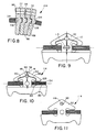
- the projection 106 and receptacle 108 therefor are shown to have a circular cross section taken in a vertical plane, the invention is not so limited. As seen in Fig. 9, the projection 110 and cooperating receptacle (not shown) can have an oval/elliptical cross section with the major axis 110 of the elliptical cross section extending generally laterally of the block body 32. Other configurations for the receptacles/projections are contemplated. For example, a square/rectangular cross section operates effectively. Any configuration that would key the projection within the recess to prevent relative rotation between adjacent block bodies 32 about a fore and aft axis are contemplated by the invention.
- the block bodies 32 in Figs. 6-9 are provided with a through bore 86, which is shown to be circular in cross section, but which could be rectangular, oval, square, or the like.
- the bore 86 communicates through channels 88, 90 with the cavity 68.
- the channels 88, 90 communicate through the bore 86 to a channel 92 communicating upwardly to the apex 94 of the head 38 as in the prior embodiment.
- Lubricating oil from below each block body 32 at the loosened side of the block bodies 32 is stored in the cavities 68 from where the oil flows upwardly by centrifugal force into the channels 88, 90 into the bore 86 for storage therein. From the bore 86, the lubricant flows out of the channel 92 at the top of the head 38 as in the prior embodiment.
- an additional channel 112 is provided and is coincident with the vertical center line C of each block body 32.
- the channel 112 originates in the base portion 36 beneath the line L and extends upwardly into communication with the bore 86. While the additional channel 112 is provided on the leading surface 54, it could be likewise provided on the trailing surface 56 to communicate with the receptacle 108 in like fashion.
- a modified form of belt is shown at 114, with the belt being similar to that 104, shown in Figs. 6-8.
- the only difference between the belt 114 and that 104 is that a porous material 116 is positioned in the bore 86 to substantially fill the bore 86.
- a belt 118 is shown that is similar to that 104 in Figs. 6-8, with the difference being that a porous material 120 is provided in the cavities 68 for retaining lubricant therewithin.
- the invention also contemplates that the porous materials 116, 120 can both be provided in the same belt block body 32.
- the porous material 116, 120 is firmly attached to the block body 32.
- that portion 122 of porous material 120 that is at the height of the steel band 34 may, over time, be worn down. Consequently, it may be desirable to provide two unconnected pieces of material to fill the upper portion 124 of the cavity and the lower portion 126 of the cavity, given that the connecting portion 122 might ultimately be worn out by the band 34.
- the lubricant in the porous material 116 flows by centrifugal force through the channel 92 to the head apex 94. Lubricant from the porous material 116 also flows readily downwardly through the channels 88, 90 to the cavity 68 to lubricate the head surface 124 and base surface 126 between which the band 34 resides. By lubricating the block body 32 and band 34, wear between the block body 32 and band 34 and heat generation are minimized.
- the material 116, 120 is made preferably of a highly porous or a fibrous material.
- the porous material is made by molding and sintering metal powder under pressure with a filler (in an amount of approximately 20-30%) therein to define a fluid path in the sintered material to permit impregnating of the material with lubricating oil.
- the metal material is preferably one of iron powder, copper powder, tin powder, carbon, or alloy powder.
- a sintered transition metal carbide such as WC, TiC, TaC or CR3C2 in combination with an iron system metal binder such as Co, Ni, or Fe can be used.
- a synthetic resin material of polytetrafluoroethylene can also be used.
- the fiber material when used, is preferably made of a natural fiber, or a flock or short fiber of woven, knit or unwoven synthetic fiber. Such a fiber member is preferably bonded with an adhesive to the surface surrounding the bore 86 and to that portion of the block body 32 bounding the cavity 68. When a short fiber is used, it is preferably flocked by spraying the same onto the surface.
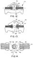
- Fig. 14 the relative movement contemplated by the invention between a projection 132 on one block body 32 for reception in a receptacle 134 on an adjacent block body 32 is shown.
- the projection 132 has a circular cross section, while the receptacle 134 is elliptical.
- the elliptical receptacle 134 is defined by arcuate surfaces 136, 138 having centers 140, spaced based equidistantly from the vertical center line c.
- Straight sections 144, 146 connect between the arcuate surfaces 136, 138 at points tangent thereto. Curved sections (not shown) could be substituted for the straight sections 144, 146.
- this arrangement of the projection 132 and receptacle 134 provides sufficient clearance to compensate for a misalignment in the widthwise direction of each block body 32.
- the projection 132 is allowed to move laterally within the receptacle 134 as to accommodate speed shifting in an automobile system, or the like.
- the projection 132 can have other than a circular configuration. However, regardless of the shape chosen, it is preferred that the range of relative lateral movement of the projection 132 in the receptacle 134 be within the .04 to .1 mm range.
- the lateral clearance is less than .04 mm, the normal contemplated lateral misalignment of the belt cannot be sufficiently compensated for. Clearance in excess of .1 mm allows sufficient lateral shifting of the block bodies 32 that the block bodies may become substantially misaligned and collide with the pulleys upon engaging the same. This results in vibration of the block bodies and wear that might precipitate premature failure.
- the band 34 and block bodies 32 are relatively dimensioned so that throughout the range of relative shifting, the laterally inwardmost edge 148 of the band 34 does not contact the neck/pillar 40 of the belt body 32.
- the spacing between the neck/pillar 40 and band 34 thus generally determines the maximum amount of relative shifting that should be allowed between adjacent block bodies.
- no additional stress is provided on the band 34 by allowing the lateral shifting between the block bodies 32.
- the lateral shifting between the block bodies 32 can occur smoothly with the projection 132 within the receptacle 134 without requiring twisting of the band 34 as would occur in the absence of the inventive structure.
Landscapes
- Engineering & Computer Science (AREA)
- General Engineering & Computer Science (AREA)
- Mechanical Engineering (AREA)
- Transmissions By Endless Flexible Members (AREA)
- General Details Of Gearings (AREA)
- Devices For Conveying Motion By Means Of Endless Flexible Members (AREA)
Description
- This invention relates to high load force transmission belts and, more particularly, to a transmission belt having a plurality of laterally self adjusting block bodies slidably mounted on an endless band, which belt is particularly adaptable to use in vehicles, such as automobiles, as well as in other environments in which speed change mechanisms are employed.
- High load transmission belts are generally categorized as either 1) pressure force transmission type or 2) tension force transmission type. The former employs a plurality of block bodies mounted in abutting relationship, each to two adjacent block bodies, slidably on an endless, multi-layer, flexible, steel band which is trained about a pair of cooperating pulleys. An exemplary belt of this type is shown in U.S. Patent 3,720,113, to VanDoorne et al.
- In the VanDoorne et al belt, the block bodies gather at the loosened side of the belt as block bodies enter into the grooves of the drive and driven pulleys. The block bodies entering the groove of the drive pulley press the gathered block bodies at the loosened side of the belt to thereby rotate the driven pulley.
- In the above type of belt, the block bodies are not interconnected so that their relative positions are not fixed. That is, they are slidable independently of each other along the endless band. Consequently, it is necessary to align the block bodies with each other so that they move consistently and without interference into and out of the pulley grooves. Exemplary guiding structure to accomplish this end is shown in each of Japanese Patent Publication Nos. 57-58543 and 55-100443. The belts disclosed in each of these publications have cooperating projections and receptacles on adjacent block bodies. Each block body has oppositely facing leading and trailing faces. The projections are shown to be on the leading face of each block body.
- In designing the belts with cooperating projections and receptacles, designers have dealt with two competing objectives. The first objective is to allow the projections to smoothly enter into and withdraw from the receptacles in operation. This is particularly a problem as the block bodies extend around the curvature of the pulleys. If the projections and receptacles were closely conforming, there would be detrimental interference between the block bodies as the projections moved into and out of the receptacles. To accommodate the belt curvature as the block bodies extend around the pulleys, the receptacles have been made sufficiently large to provide clearance for the projections. This has made difficult the achievement of the second objective of belt designers - that of preventing rattling between adjacent blocks. There is a substantial amount of play permitted between adjacent block bodies which, in use, may result in the block bodies rattling in the absence of perfect alignment therebetween.
- Another problem that has plagued the industry is that of the projections fully withdrawing from the receptacles as the block bodies traverse the curvature of the pulleys. If the projections are too tightly received in the receptacles, the block bodies may not completely conform to pulleys, particularly small diameter pulleys. That is, the block bodies tend to bridge across the pulley grooves, which reduces the contact area between the block bodies and the cooperating pulleys. Too loose a fit between the projections and receptacles may result in the block bodies completely separating from each other resulting in misalignment of adjacent bodies and possible prevention of the projection from reentering the cooperating receptacle.
- Another problem with the above-mentioned belt systems is that there is a substantial amount of friction generation between the endless band and the block bodies. In Fig. 1 of the drawings herein, a prior art system is shown schematically in which a lubricant is directed outwardly against a belt trained around a pair of pulleys to alleviate this problem. The lubricant is propelled at the point of entry of the block bodies into the driven pulley. The centrifugal force developed by the rotating pulleys causes the lubricant to spray radially outwardly so that much of the lubricant produces no beneficial effect.
- In an exemplary belt system of the type described above, each block body has a base, a head, and a neck/pillar connecting between the base and head and defining a slot for reception of an endless band. The block bodies between the drive and driven pulleys are forcibly engaged at the heads and necks/pillars above an inclination line about which the block bodies pivot relative to each other in conforming to a pulley. In operation, there are vibrations which cause contacting block body portions to abrade each other. As a result, the block bodies may wear excessively over time, particularly in environments where the pressure between adjacent block bodies is substantial.
- One solution to the above problem has been to increase the contact area between adjacent block bodies. This increases the pressure receiving surface area of each block body to reduce the force per unit area. While this solution does reduce the problem of wear, it also increases the belt weight and causes considerable increase in the centrifugal forces developed at high speed operation of the system. As a result, the transmission capability of the belt may be diminished.
- The present invention is specifically directed to overcoming the above-enumerated problems in a novel and simple manner.
- In GB-A-1549403, there is disclosed a drive arrangement comprising a driving belt composed of driving elements of substantially non-compressible material slidably arranged on an endless carrier, and at least two V-shaped pulleys over which the belt is passed. Each driving element has at least two converging side faces arranged to co-operate with the inner surface of the side plates of the pulleys. Either the converging side faces of the element or the inner surface of the side plates or both the converging side faces of the element and the inner surface of the side plates are formed as a non-continuous surface.
- In EP-A-0381258, there is disclosed a transmission provided with at least one driving belt and V-shaped pulleys. The driving belt comprises one or more transverse elements provided with converging side faces for intermating with contact surfaces of the V-shaped pulleys, and one or more side faces of one or more transverse elements and/or the contact surfaces of the V-shaped pulleys are designed as a non-continuous surface, by means of one or more grooves located between ridges. The grooves take up at least 50% of the entire surface in which they are present.
- In EP-A-0296397, there is disclosed a power transmitting V-belt comprising an endless metal band mounted on a multiplicity of V-shaped metal blocks lined to one another, with a semi-cylindrical recess extending in a widthwise direction of the metal band being provided on one V-shaped metal block and engaged by a semi-cylindrical projection associated with an adjacent metal block to provide a pivotable linkage between said adjacent V-shaped metal blocks. A relief portion having a predetermined axial length is provided at an axially central portion of the semi-cylindrical recess and projection for eliminating or minimizing the engagement therebetween at the central portion.
- According to the present invention, there is provided a force transmission belt comprising:
a plurality of block bodies each having laterally spaced pulley-engaging surfaces;
an endless band to be trained about a pair of pulleys; and
cooperating means on the endless band and the block bodies for maintaining the block bodies in operative position on the endless band in which the block bodies are slidable lengthwise of the endless band and positioned so that the laterally spaced pulley-engaging surfaces can frictionally engage a pulley about which the endless band is trained;
characterised in that the belt further comprises channel means in at least one of the block bodies for guiding lubricant from a point between the one block body and the endless band to a location outside of the one block body to minimize wear between the adjacent block bodies, said channel means including an identifiable non-straight channel requiring lubricant to follow a non-straight path in moving through the one block body between said point between the one block body and endless band and the location outside the one block body. - The present invention also provides a force transmission belt comprising:
a plurality of block bodies each having laterally spaced pulley-engaging surfaces and leading and trailing faces;
an endless band to be trained about a pair of pulleys;
cooperating means on the endless band and the block bodies for maintaining the block bodies in operative position on the endless band in which the block bodies are slidable lengthwise of the endless band and positioned so that the laterally spaced pulley-engaging surfaces can frictionally engage a pulley about which the endless band is trained;
a projection on one of the leading and trailing faces of a first one of the block bodies; and
a receptacle for the projection on the other of the leading and trailing faces of a second of the block bodies adjacent to the one block body, said projection being extendable into the receptacle to maintain the first and second block bodies in a desired relative operative relationship;
characterised in that the belt further comprises channel means in at least one of the first and second block bodies for guiding lubricant from a point between at least one of the projection and receptacle to a location outside of the one block body to facilitate movement of the projection within the receptacle and minimize wear between adjacent block bodies, said channel means including an identifiable non-straight channel requiring lubricant to follow a non-straight path in moving through the one block body between said point between the one block body and endless band and the location outside the one block body. - The present invention further provides a block body for sliding engagement with an endless band to be trained around a pair of pulleys, said block body being operatively positioned on an endless band to drive/be driven by a pulley about which the endless band is trained, said block body comprising:
a base portion defining drive/driven surfaces for engagement with a pulley;
a head portion; and
a neck/pillar portion connecting between the base and head portions to maintain the head and base portions in a predetermined spaced relationship with a slot therebetween for reception of an endless band;
characterised in that said block body further comprises channel means for guiding lubricant through the block body from the slot to a location outside of the block body, said channel means including an identifiable non-straight channel requiring lubricant to follow a non-straight path in moving through the one block body between said point between the one block body and endless band and the location outside the one block body. - The present invention further provides a block body for sliding engagement with an endless band to be trained around a pair of pulleys, said block body having oppositely facing leading and trailing faces and being operatively positioned on an endless band to drive/be driven by a pulley about which the endless band is trained, said block body comprising:
a base portion defining drive/driven surfaces for engagement with a pulley;
a head portion;
a neck/pillar portion connecting between the base portion and head portion, said endless band being captively held between the head and base portions; and
guide means on at least one of the leading and trailing faces to cooperate with an adjacent block to maintain an operative aligned relationship between adjacent block bodies;
characterised in that said block body further comprises channel means for guiding lubricant through the one block body from the guide means to a location outside of the block body, said channel means including an identifiable non-straight channel requiring lubricant to follow a non-straight path in moving through the one block body between said point between the one block body and endless band and the location outside the one block body. - It is the principal objective of the present invention to provide a high load force transmission belt that is: highly durable; self-lubricating; smoothly operable with self-aligning block bodies that are not prone to rattling; readily conformable to relatively small diameter pulleys; and capable of withstanding a substantial amount of pressure during operation without a large surface contact area between adjacent blocks.
- More particularly, the invention contemplates a force transmission belt having a plurality of block bodies each with laterally spaced pulley-engaging surfaces, an endless band to be trained about a pair of pulleys, cooperating structure on the endless band and the block bodies for maintaining the block bodies in an operative position on the endless band with the block bodies slidable lengthwise of the endless band and positioned so that the laterally spaced pulley-engaging surfaces fractionally engage a pulley about which the endless band is trained, and channel structure in at least one of the block bodies for guiding lubricant from a point between the one block body and the endless band to a location outside of the one block body to minimize wear between the one block body and the endless band in the vicinity of that point, said channel means including a non-straight channel requiring lubricant to follow a non-straight path in moving through the one block body between said point between the one block body and endless band and the location outside the one block body.
- In one form of the block body, there is a base portion defining pulley-engaging surfaces, a head portion, and a neck/pillar portion connecting between the base and head portions. The endless band is captively held between the head and base portions.
- According to the invention, the channel structure can take a variety of different forms. The channels can be enclosed bores through the block bodies or undercut(s) in at least one face of the block bodies.
- In one form, the channel structure includes a channel extending from the bottom side of the one block body base upwardly through the one block body base to the point between the one block body and endless band.
- In one form of the invention, one block body has a leading and a trailing face spaced in a fore and aft direction and the channel structure includes a bore extending fully through the one block body in the fore and aft direction. A continuous pathway for the lubricant can be defined from a point between the one block body and endless band to and through the bore in the head. In one form, the bore extends through the head on the one block body.
- In one form of the invention, there is a recess in the one block body defining a cavity bounded by the endless band and the one block body to define a lubricant reservoir at the point between the one block body and endless band.
- The invention also contemplates the provision of porous material in the channel structure/bore to retain a supply of lubricant. The porous material is provided in at least one of the cavity and the bore.
- The invention also contemplates a force transmission belt having a plurality of block bodies each having laterally spaced pulley-engaging surfaces, an endless band to be trained about a pair of pulleys, cooperating structure on the endless band and the block bodies for maintaining the block bodies in operative position on the endless band in which the block bodies are slidable lengthwise of the endless band and positioned so that the laterally spaced pulley-engaging surfaces can frictionally engage a pulley about which the endless band is trained, a projection on one of the leading and trailing faces on a first one of the block bodies, a receptacle for the projection on the other of the leading and trailing faces of a second of the block bodies adjacent to the one block body with the projection being extendable into the receptacle to maintain the first and second block bodies in a desired relative operative relationship, and channel structure in at least one of the first and second block bodies to guide lubricant from a point between at least one of the projection and receptacle to a location outside of the one block body to facilitate movement of the projection within the receptacle and minimize wear between adjacent block bodies in operation.
- The lubricant at the projection/receptacle minimizes abrasion between adjacent block bodies as the projection moves into and is withdrawn from the receptacle in use.
- In a preferred form, the first and second block bodies each have a base portion, a head portion and a neck/pillar portion connecting between the base portion and head portion, with there being a slot between the head and base portions in which the endless band is captively held.
- The channel structure can be similar to that previously described for directing lubricant from the point between the block body and endless band to outside of the block bodies.
- The invention also contemplates the combination of channel structure for simultaneously lubricating the connecting structure and the slot in the block bodies that receives the endless band. Porous material can also be placed in the channel structure as previously described.
- The invention further contemplates a block body having a base defining drive/driven surfaces for engagement with a pulley, a head portion, a neck/pillar portion connecting between the base and head portions to maintain the head and base portions in a predetermined spaced relationship with a slot therebetween for reception of an endless band, and channel structure for guiding lubricant through the block body from the slot to a location outisde of the block body.
- The channel structure can include, for example, a bore extending fully through the block body in a fore and aft direction, a channel communicating from the bore into the apex of the head portion and a channel communicating from the slot to the bore. The channels can be straight, but preferably the channel from the bore to the slot is non-straight and exposed at at least one of the leading and trailing faces of the block body to cause the distribution of a substantial amount of lubricant over the one face.
- The invention further contemplates a block body with a base, head portion, and neck/pillar portion as described above, further including guide structure on adjacent block bodies with channel structure for guiding lubricant through one of the block bodies from the guide structure.
- The channel structure may include, for example, a through bore in the head portion, a channel communicating between the bore and the apex of the head portion and a channel communicating from the guide structure to the bore.
- The channel structure is preferably exposed at at least one of the leading and trailing block body faces so that the contacting area of the head and neck/pillar portions between adjacent block bodies is lubricated to reduce wear therebetween.
- Lubricant is stored effectively in the block body cavities and through bores to be distributed therefrom through the channels. The channel from the through bore to the apex assures that lubricant is evenly distributed at the upper region of the head portion. The lubricant flows upwardly out of the head portions for superior lubrication. The through bore is replenished with lubricant driven by centrifugal force from the cavity into the through bore through one or more channels.
- The invention still further contemplates that adjacent block bodies of the plurality thereof form a block body pair consisting of: first and second block bodies each having a base portion defining laterally spaced pulley-engaging surfaces, a head portion, a neck/pillar portion connecting between the base portion and the head portion to maintain the base and head portions a predetermined distance away from each other with a slot being defined therebetween for reception of an endless band, and oppositely facing leading and trailing faces; a projection on one of the leading and trailing faces on one of the first and second block bodies, which projection has a substantially circular first cross section taken in a vertical plane extending laterally through the one of the first and second block bodies; and a receptacle in the other of the leading and trailing faces on the other of the first and second block bodies which has a non-circular second cross section taken in a vertical plane extending laterally through the other of the first and second block bodies.
- Preferably, the receptacle has an elliptical second cross section with the major axis of the elliptical second cross section extending in a lateral direction.
- This construction allows relative lateral shifting between adjacent block bodies to accommodate, for example, speed shifting. Preferably, the relative lateral shifting permitted is in the range of .04 to .1 mm. This obviates the need for the block bodies to self adjust by twisting, which places undesired stresses on the endless band. The life of the endless band is resultingly increased.
- The invention still further contemplates that adjacent block bodies of the plurality thereof form a a block body pair with a projection and receptacle, one each on the block bodies in the pair and having first and second cross sections taken in a vertical plane extending laterally through the block bodies, with the first and second cross sections being dimensioned to allow relative shifting between the projection and receptacle in at least one of the vertical and lateral directions.
- Preferably, the amount of shifting is on the order of between .04 to .1 mm. Preferably, the second receptacle cross section has a larger lateral dimension than vertical dimension to accommodate relative lateral shifting between the block bodies in the pair.
- The invention still further contemplates that adjacent block bodies of the plurality thereof form a a block body for sliding engagement with an endless band to be trained around a pair of pulleys, which block body has a base portion defining laterally spaced pulley-engaging surfaces, a head portion, a neck/pillar portion, and oppositely facing leading and trailing faces. The first and second laterally spaced projections are provided on one of the leading and trailing faces on the neck/pillar portion for engagement with corresponding receptacles on an adjacent block body.
- This latter configuration limits skewing of adjacent block bodies by relative rotation about the fore and aft axes for the block bodies.
- In one form, the neck/pillar portion has laterally spaced edges and the projections are provided one each at the laterally spaced edges of the neck/pillar portion.
- Alternatively, to limit relative rotation of the block bodies about the fore and aft axis, a single projection can be keyed in its receptacle. This can be accomplished by making the matching cross sections of each of the projections and receptacles non-circular, i.e. square, rectangular, oval, or other polygonal shapes.
- Preferably, the projections penetrate the cooperating receptacles therefor at all times, as when the belt conforms to a small diameter pulley, to prevent misalignment between adjacent block bodies and possible interference between the projection and an adjacent block body as the projection moves to reenter the receptacle.
- With the inventive structure, the adjacent, aligned block bodies smoothly enter into the pulley grooves. This avoids noise development that would otherwise occur as misaligned block bodies impact a pulley. In addition to reducing noise, vibration development is minimized as is wear on the belt and pulley. The result is that the belt positively drives, and is positively driven by, the pulleys.
- Reference will now be made, by way of example, to the drawings in which:
- Fig. 1 is a schematic, side elevation view of a conventional force transmission belt with block bodies operatively positioned on an endless band trained about spaced pulleys and with a lubricant being propelled against the force transmission belt at the point where it enters a driven pulley;
- Fig. 2 is an elevation view of a transmission belt, according to the present invention, taken from one end of a block body operatively positioned on an endless band;
- Fig. 3 is a view as in Fig. 2 taken from the block body end opposite that in Fig. 2;
- Fig. 4 is a cross-sectional view of the inventive transmission belt taken along line 4-4 of Fig. 2;
- Fig. 5 is a view as in Fig. 3 with the block body modified to include additional channel structure for guiding the delivery of a lubricant;
- Fig. 6 is an elevation view of a modified form of transmission belt, according to the present invention, from one end of a block body operatively positioned on an endless band;
- Fig. 7 is a view as in Fig. 6 taken from the block body end opposite that in Fig. 6;
- Fig. 8 is a cross-sectional view of the modified transmission belt taken along line 8-8 of Fig. 6;
- Fig. 9 is an end elevation view of a further modified form of transmission belt according to the present invention;
- Fig. 10 is an elevation view of a further modified form of transmission belt, according to the present invention, taken from one end of a block body operatively positioned on an endless band;
- Fig. 11 is a view as in Fig. 10 taken from the block body end opposite that in Fig. 10;
- Fig. 12 is an elevation view of a still further modified form of transmission belt, according to the present invention, taken from one end of a block body operatively positioned on an endless band;
- Fig. 13 is a view as in Fig. 12 taken from the block body end opposite that in Fig. 12; and
- Fig. 14 is an enlarged end elevation view of two cooperating block bodies, according to the present invention, showing the permissible range of relative lateral movement between the blocks.
- In Fig. 1, a prior art transmission system is shown at 10 including a
drive pulley 12 and a drivenpulley 14 rotatable about spaced,parallel axes force transmission belt 20 is trained around thepulleys block bodies 24 are slidably mounted. - A
lubrication source 26 resides within the periphery of the belt loop and propels lubricant outwardly towards the region at which thebelt 20 moves against the drivenpulley 14. The problem with the lubrication system in Fig. 1 is that a substantial amount of the lubricant will contact the rotating drivenpulley 14. The centrifugal force produced by the rotation of thepulley 14, particularly at high speeds, causes the lubricant to spray radially outwardly from thepulley 14 and thus thebelt 20 which it draws in an arcuate path, so that a substantial portion of the delivered lubricant produces no beneficial effect. One of the objectives of the present invention is to avoid the shortcomings of a system such as that in Fig. 1. - In Figs. 2-4, a first form of transmission belt, according to the present invention, is shown at 30. The
belt 30 consists of a plurality ofblock bodies 32 arranged slidably along the length of an endless,multi-layered steel band 34, which is arranged to be trained around a pair of cooperating pulleys. Theblock bodies 32 are arranged around the entire length of theband 34 in abutting relationship, each to adjacent block bodies on its opposite faces. Theendless band 34 may be pretensioned so that there is a residual force causing theblock bodies 32 to be borne against each other. - Each
block body 32 consists of abase portion 36, an inverted, V-shapedhead portion 38, and a neck/pillar portion 40 connecting between the base andhead portions slots slot flexible band 34. Thebase portion 36 of eachblock body 32 has laterally oppositely facing, inclined side surfaces/edges pulley 52. - Each
block body 32 has oppositely facing, leading and trailing faces, 54, 56, spaced in a fore and aft direction. The leadingface 54 has aportion 58 that is inclined to the vertical, from a laterally extending inclination line L, to allow theblock bodies 32 to pivot relative to each other to conform to the curvature of thepulley 52 in operation. As can be seen in Fig. 4, theblock bodies 32 reposition by pivoting about anedge 60, coincident with the line L, which serves as a fulcrum, to bring the trailingface 56 facially against the leadingface 54 on an adjacent, trailingblock body 32. The belt pitch line P coincides with theedge 60 on which theblock bodies 32 pivot as well as with the inclination line L of thebase portions 36 of theblock bodies 32. - The
slots block bodies 32 are similar in configuration, and thusexemplary slot 42 will be used herein for purposes of illustration. Theslot 42 has a vertical dimension between theunderside surface 62 of thehead 38 and a facingbase surface 64 that is slightly larger than the vertical dimension of theband 34. - A curved, downwardly opening
upper recess 64 is provided in thehead 38. A like, lower, upwardly openingrecess 66 is provided on the base 36 so that therecesses cavity 68 surrounding the laterally innermost portion of theband 34 and defining a lubricant reservoir, the function of which is described more fully below. The bottom of therecess 66 coincides with the inclination line L. An undercutlubricant guiding channel 70 extends from the front to the rear of theblock body 32 and communicates with the lower recess. - The neck/
pillar portion 40 of theblock body 32 has similarly-shapedprojections projections pillar portion 40. Theprojections - On the opposite/trailing
surface 56 of theblock body 32,receptacles projections adjacent block body 32. The cooperatingprojections receptacles adjacent block bodies 32 to maintain alignment of the pulley engaging side surfaces 46, 48 on theblock bodies 32 to account for smooth entry into and withdrawal of thebelt 30 from pulley grooves. The spaced arrangement of theprojections receptacles adjacent block bodies 32 from rotating relative to each other about the fore and aft axes for the block bodies. - The
projections receptacles projections receptacles block bodies 32 on the righthand side of that Figure are tilted to a maximum position i.e. to accommodate the smallestpossible diameter pulley 52. In that position, theprojections 72 remain within thereceptacles 80. In the absence of this feature, theadjacent block bodies 32 might misalign relative to each other which may further result in theprojections receptacles misaligned block bodies 32 may thus forcibly impact thepulleys 52 which may generate unwanted noise and cause wear on thebelt 30 and/orpulley 52, which may precipitate early system failure. - The invention further contemplates channel means at 84 for controllably guiding the passage of lubricant from the
cavity 68 to a point externally of theblock body 32. The channel means 84 includes abore 86 extending fully through theblock body head 38 in a fore and aft direction. Achannel 88 communicates between thebore 86 and thecavity 68, with their being asimilar channel 90 projecting oppositely away from the throughbore 86. Thecavity 68 defines a reservoir for lubricating oil which lubricates the engaging surfaces on theblock body 32 andband 34 within thecavity 68. Aseparate channel 92 communicates between thebore 86 and the apex 94 of the inverted, V-shapedhead portion 38. - In operation, lubricating oil flows from the
cavity 68 by centrifugal force to aninlet 96 to thechannel 88, through thebore 86 and into thechannel 92. Through this arrangement, oil flows out of thechannels head portion 38 so that the contacting surfaces betweenadjacent block bodies 32 is effectively lubricated to minimize wear therebetween during operation. Lubrication is enhanced by the lubricant flowing from thebore 86 to thechannel 92 and to the top of thehead portion 38 of theblock body 32. - The
bore 86 preferably has a diameter of 2-3 mm. Thelubricating channels - In the slackened portions of the belt, a supply of lubricant in the
bore 86 is constantly delivered through thechannels band 34 occupies theslot 42. To enhance the amount of lubrication on the face(s) of theblock body head 38, thechannels head 38 on at least one of thefaces - A modified form of the
block body 32 in Figs. 2-4 is shown in Fig. 5. In Fig. 5, the block body hasvertical channels bottom side 102 of theblock body 32 to thecavities 68 between thehead 38 andbase 36 of eachblock body 32. - By feeding the
cavity 68 continuously with lubricant, in addition to reducing wear between theband 34 and blockbodies 32, the lubricant spreads over theprojections receptacles projections receptacles - It should be understood that while all of the channel means 84 described herein are shown to be on one surface of the block body, the invention also contemplates, for enhanced lubrication, that the channel means 84 could be provided on both
surfaces block bodies 32. - In Figs. 6-8, a modified form of transmission belt, according to the present invention, is shown at 104. Elements on the
belt 104 corresponding to those on thebelt 30, shown in Figs. 3-4, are correspondingly numbered. Thebelt 104 has correspondingblock bodies 32, each having abase portion 36, ahead portion 38 and an interconnecting neck/pillar portion 40. - Instead of the pairs of
projections receptacles single projection 106 is provided on the leadingblock body face 54 for receipt in areceptacle 108 on the trailingblock body surface 56. Theprojection 106 has a cylindrical configuration along substantially its entire extent in a fore and aft direction and is symmetrical about the vertical center line C for theblock body 32. Theprojection 106 andreceptacle 108 are provided in the neck/pillar portion 40 of theblock body 42 with their centers at the intersection of the vertical center line C and the lateral center line M of theendless band 34. Alternatively, as shown in phantom lines in Figs. 6 and 7, theprojection 106 andreceptacle 108 can be positioned lower on theblock body 32 so that the bottoms of theprojection 106 andreceptacle 108 coincide with the inclination line L. - The cooperating
projection 106 andreceptacle 108 guide relative movement betweenadjacent block bodies 32. As seen in Fig. 8, theprojection 106 remains within thereceptacle 108 for the maximum bending contemplated for thebelt 104 i.e. with thebelt 104 conforming to the smallest possible pulley diameter. As seen in Fig. 8, this condition exists when theinclined portion 58 on the leadingsurface 54 of oneblock body 32 facially engages the trailingsurface 56 on anadjacent block body 32. - While the
projection 106 andreceptacle 108 therefor are shown to have a circular cross section taken in a vertical plane, the invention is not so limited. As seen in Fig. 9, theprojection 110 and cooperating receptacle (not shown) can have an oval/elliptical cross section with themajor axis 110 of the elliptical cross section extending generally laterally of theblock body 32. Other configurations for the receptacles/projections are contemplated. For example, a square/rectangular cross section operates effectively. Any configuration that would key the projection within the recess to prevent relative rotation betweenadjacent block bodies 32 about a fore and aft axis are contemplated by the invention. - As in the earlier described
belt embodiment 30, theblock bodies 32 in Figs. 6-9 are provided with a throughbore 86, which is shown to be circular in cross section, but which could be rectangular, oval, square, or the like. Thebore 86 communicates throughchannels cavity 68. Thechannels bore 86 to achannel 92 communicating upwardly to the apex 94 of thehead 38 as in the prior embodiment. Lubricating oil from below eachblock body 32 at the loosened side of theblock bodies 32 is stored in thecavities 68 from where the oil flows upwardly by centrifugal force into thechannels bore 86 for storage therein. From thebore 86, the lubricant flows out of thechannel 92 at the top of thehead 38 as in the prior embodiment. - To reduce noise between
adjacent block bodies 32 and to avoid wear on the guidingprojection 106 andreceptacle 108, anadditional channel 112 is provided and is coincident with the vertical center line C of eachblock body 32. Thechannel 112 originates in thebase portion 36 beneath the line L and extends upwardly into communication with thebore 86. While theadditional channel 112 is provided on the leadingsurface 54, it could be likewise provided on the trailingsurface 56 to communicate with thereceptacle 108 in like fashion. - In Figs. 10 and 11, a modified form of belt is shown at 114, with the belt being similar to that 104, shown in Figs. 6-8. The only difference between the
belt 114 and that 104 is that aporous material 116 is positioned in thebore 86 to substantially fill thebore 86. In Figs. 12 and 13, abelt 118 is shown that is similar to that 104 in Figs. 6-8, with the difference being that aporous material 120 is provided in thecavities 68 for retaining lubricant therewithin. The invention also contemplates that theporous materials belt block body 32. - Preferably, the
porous material block body 32. As seen in Figs. 12 and 13, thatportion 122 ofporous material 120 that is at the height of thesteel band 34 may, over time, be worn down. Consequently, it may be desirable to provide two unconnected pieces of material to fill theupper portion 124 of the cavity and thelower portion 126 of the cavity, given that the connectingportion 122 might ultimately be worn out by theband 34. - The lubricant in the
porous material 116 flows by centrifugal force through thechannel 92 to thehead apex 94. Lubricant from theporous material 116 also flows readily downwardly through thechannels cavity 68 to lubricate thehead surface 124 andbase surface 126 between which theband 34 resides. By lubricating theblock body 32 andband 34, wear between theblock body 32 andband 34 and heat generation are minimized. - The
material - The fiber material, when used, is preferably made of a natural fiber, or a flock or short fiber of woven, knit or unwoven synthetic fiber. Such a fiber member is preferably bonded with an adhesive to the surface surrounding the
bore 86 and to that portion of theblock body 32 bounding thecavity 68. When a short fiber is used, it is preferably flocked by spraying the same onto the surface. - In Fig. 14, the relative movement contemplated by the invention between a
projection 132 on oneblock body 32 for reception in areceptacle 134 on anadjacent block body 32 is shown. Theprojection 132 has a circular cross section, while thereceptacle 134 is elliptical. Theelliptical receptacle 134 is defined byarcuate surfaces centers 140, spaced based equidistantly from the vertical center line c.Straight sections arcuate surfaces straight sections - As previously discussed, this arrangement of the
projection 132 andreceptacle 134 provides sufficient clearance to compensate for a misalignment in the widthwise direction of eachblock body 32. Theprojection 132 is allowed to move laterally within thereceptacle 134 as to accommodate speed shifting in an automobile system, or the like. - The invention also contemplates that the
projection 132 can have other than a circular configuration. However, regardless of the shape chosen, it is preferred that the range of relative lateral movement of theprojection 132 in thereceptacle 134 be within the .04 to .1 mm range. - If the lateral clearance is less than .04 mm, the normal contemplated lateral misalignment of the belt cannot be sufficiently compensated for. Clearance in excess of .1 mm allows sufficient lateral shifting of the
block bodies 32 that the block bodies may become substantially misaligned and collide with the pulleys upon engaging the same. This results in vibration of the block bodies and wear that might precipitate premature failure. - As seen in Fig. 14, the
band 34 and blockbodies 32 are relatively dimensioned so that throughout the range of relative shifting, the laterallyinwardmost edge 148 of theband 34 does not contact the neck/pillar 40 of thebelt body 32. The spacing between the neck/pillar 40 andband 34 thus generally determines the maximum amount of relative shifting that should be allowed between adjacent block bodies. Thus, no additional stress is provided on theband 34 by allowing the lateral shifting between theblock bodies 32. The lateral shifting between theblock bodies 32 can occur smoothly with theprojection 132 within thereceptacle 134 without requiring twisting of theband 34 as would occur in the absence of the inventive structure. - The foregoing disclosure of specific embodiments is intended to be illustrative of the broad concepts comprehended by the invention.
Claims (14)
- A force transmission belt (30, 104, 114, 118) comprising:
a plurality of block bodies (32) each having laterally spaced pulley-engaging surfaces (46, 48);
an endless band (34) to be trained about a pair of pulleys; and
cooperating means on the endless band (34) and the block bodies (32) for maintaining the block bodies (32) in operative position on the endless band (34) in which the block bodies (32) are slidable lengthwise of the endless band (34) and positioned so that the laterally spaced pulley-engaging surfaces (46, 48) can frictionally engage a pulley about which the endless band (34) is trained;
characterised in that the belt (30, 104, 114, 118) further comprises channel means (84) in at least one of the block bodies (32) for guiding lubricant from a point between the one block body (32) and the endless band (34) to a location outside of the one block body (32) to minimize wear between the adjacent block bodies (32), said channel means (84) including an identifiable non-straight channel (88, 90) requiring lubricant to follow a non-straight path in moving through the one block body (32) between said point between the one block body (32) and endless band (34) and the location outside the one block body (32). - A belt (30, 104, 114, 188) according to claim 1 wherein said one block body (32) has a base portion (36) defining the pulley-engaging surfaces (46, 48), a head portion (38) and a neck/pillar portion (40) connecting between the base portion (36) and the head portion (38), said endless band (34) being captively held between the head and base portions (38, 36).
- A belt (30, 104, 114, 118) according to claim 2 wherein the one block body base portion (36) has a bottom side (102) and the channel means (84) includes a channel (98, 100) extending from the bottom side (102) of the one block body base portion (36) upwardly through the one block body base portion (36) to said point.
- A belt (30, 104, 114, 118) according to claim 2 wherein the channel means (84) includes a channel (92) extending through the one block body head portion (38) to said point.
- A belt (30, 104, 114, 118) according to claim 2 wherein the one block body (32) has a leading and a trailing face (54, 56) spaced in a fore and aft direction and the channel means (84) includes a bore (86) extending fully through the one block body (32) in the fore and aft direction.
- A belt (30, 104, 114, 118) according to claim 5 wherein the bore (86) extends through the head portion (38) on the one block body (32).
- A belt (30, 104, 114, 118) according to claim 5 wherein the channel means (84) includes a channel (88, 90) communicating between the bore (86) and said point.
- A belt (30, 104, 114, 118) according to claim 1 wherein there is a recess in said one block body defining a cavity (68) bounded by the endless band (34) and the one block body (32) to define a lubricant reservoir at said point.
- A belt (30, 104, 114, 118) according to claim 1 wherein there is a porous material (116) in at least a part of said channel means (84) for retaining a supply of lubricant.
- A belt (30, 104, 114, 118) according to claim 6 wherein the one block body head portion (36) has a top side with an apex (94) thereat and the channel means (84) includes a channel (92) communicating from the bore (86) to the apex (94).
- A belt (30, 104, 114, 118) according to claim 8 wherein there is a porous material (120) in said cavity (68) for retaining a supply of lubricant.
- A force transmission belt (30, 104, 114, 118) comprising:
a plurality of block bodies (32) each having laterally spaced pulley-engaging surfaces (46, 48) and leading and trailing faces (54, 56);
an endless band (34) to be trained about a pair of pulleys;
cooperating means on the endless band (34) and the block bodies (32) for maintaining the block bodies (32) in operative position on the endless band (34) in which the block bodies (32) are slidable lengthwise of the endless band (34) and positioned so that the laterally spaced pulley-engaging surfaces (46, 48) can frictionally engage a pulley about which the endless band (34) is trained;
a projection (72, 74, 106, 110, 132) on one of the leading and trailing faces (54, 56) of a first one of the block bodies (32); and
a receptacle (80, 82, 108, 134) for the projection (72, 74, 106, 110, 132) on the other of the leading and trailing faces (54, 56) of a second of the block bodies (32) adjacent to the one block body (32), said projection (72, 74, 106, 110, 132) being extendable into the receptacle (80, 82, 108, 134) to maintain the first and second block bodies (32) in a desired relative operative relationship;
characterised in that the belt (30, 104, 114, 118) further comprises channel means (84) in at least one of the first and second block bodies (32) for guiding lubricant from a point between at least one of the projection (72, 74, 106, 110, 132) and an identifiable receptacle (80, 82, 108, 134) to a location outside of the one block body (32) to facilitate movement of the projection (72, 74, 106, 110, 132) within the receptacle (80, 82, 108, 132) and minimize wear between adjacent block bodies (32), said channel means (84) including an identifiable non-straight channel (88, 90) requiring lubricant to follow a non-straight path in moving through the one block body (32) between said point between the one block body (32) and endless band (34) and the location outside the one block body (32). - A block body (32) for sliding engagement with an endless band (34) to be trained around a pair of pulleys, said block body (32) being operatively positioned on an endless band (34) to drive/be driven by a pulley about which the endless band (34) is trained, said block body (32) comprising:
a base portion (36) defining drive/driven surfaces (46, 48) for engagement with a pulley;
a head portion (38); and
a neck/pillar portion (40) connecting between the base and head portions (36, 38) to maintain the head and base portions (36, 38) in a predetermined spaced relationship with a slot (42, 44) therebetween for reception of an endless band (34);
characterised in that said block body (32) further comprises channel means (84) for guiding lubricant through the block body (32) from the slot (42, 44) to a location outside of the block body (32), said channel means (84) including an identifiable non-straight channel (88, 90) requiring lubricant to follow a non-straight path in moving through the one block body (32) between said point between the one block body (32) and endless band (34) and the location outside the one block body (32). - A block body (32) for sliding engagement with an endless band (34) to be trained around a pair of pulleys, said block body (32) having oppositely facing leading and trailing faces (54, 56) and being operatively positioned on an endless band (34) to drive/be driven by a pulley about which the endless band (34) is trained, said block body (32) comprising:
a base portion (36) defining drive/driven surfaces (46, 48) for engagement with a pulley;
a head portion (38);
a neck/pillar portion (40) connecting between the base portion (36) and head portion (38), said endless band (34) being captively held between the head and base portions (38, 36); and
guide means on at least one of the leading and trailing faces (54, 56) to cooperate with an adjacent block (32) to maintain an operative aligned relationship between adjacent block bodies (32);
characterised in that said block body (32) further comprises channel means (84) for guiding lubricant through the one block body (32) from the guide means to a location outside of the block body (32), said channel means (84) including an identifiable non-straight channel (88, 90) requiring lubricant to follow a non-straight path in moving through the one block body (32) between said point between the one block body (32) and endless band (34) and the location outside the one block body (32).
Applications Claiming Priority (6)
| Application Number | Priority Date | Filing Date | Title |
|---|---|---|---|
| JP198328/90 | 1990-07-25 | ||
| JP19832890 | 1990-07-25 | ||
| JP241564/90 | 1990-09-11 | ||
| JP2241564A JP2608800B2 (en) | 1990-07-25 | 1990-09-11 | High load transmission belt |
| JP2412184A JPH0781610B2 (en) | 1990-12-18 | 1990-12-18 | High load transmission belt |
| JP804991U JPH04101846U (en) | 1991-01-28 | 1991-01-28 | High load transmission belt |
Publications (3)
| Publication Number | Publication Date |
|---|---|
| EP0468770A2 EP0468770A2 (en) | 1992-01-29 |
| EP0468770A3 EP0468770A3 (en) | 1992-05-20 |
| EP0468770B1 true EP0468770B1 (en) | 1995-09-06 |
Family
ID=27454854
Family Applications (1)
| Application Number | Title | Priority Date | Filing Date |
|---|---|---|---|
| EP91306755A Expired - Lifetime EP0468770B1 (en) | 1990-07-25 | 1991-07-24 | High load force transmission belt |
Country Status (4)
| Country | Link |
|---|---|
| US (1) | US5169369A (en) |
| EP (1) | EP0468770B1 (en) |
| AU (1) | AU641260B2 (en) |
| CA (1) | CA2047048C (en) |
Families Citing this family (29)
| Publication number | Priority date | Publication date | Assignee | Title |
|---|---|---|---|---|
| JP3126811B2 (en) * | 1992-06-16 | 2001-01-22 | 本田技研工業株式会社 | Metal block for detecting the acting force of metal V-belt and acting force detecting device using the same |
| US5439422A (en) * | 1993-05-24 | 1995-08-08 | Van Doorne's Transmissie B.V. | Drive belt |
| US5533940A (en) * | 1994-05-24 | 1996-07-09 | Van Doorne's Transmissie B.V. | Drive belt |
| WO1997025552A1 (en) * | 1996-01-13 | 1997-07-17 | Bogey Venlo B.V. | Belt for a transmission as well as transmission with belt |
| NL1003354C2 (en) * | 1996-06-17 | 1997-12-19 | Bogey Venlo B V | Belt for transmission of torque between two or more rotary bodies |
| JP3319995B2 (en) * | 1997-10-14 | 2002-09-03 | 本田技研工業株式会社 | Belt for continuously variable transmission |
| JP3901356B2 (en) * | 1998-09-02 | 2007-04-04 | 本田技研工業株式会社 | Belt for continuously variable transmission |
| JP3527418B2 (en) * | 1998-08-31 | 2004-05-17 | 本田技研工業株式会社 | Metal V belt |
| JP4505068B2 (en) * | 1999-01-08 | 2010-07-14 | 本田技研工業株式会社 | Metal belt |
| JP3737000B2 (en) * | 1999-09-08 | 2006-01-18 | 本田技研工業株式会社 | Belt for continuously variable transmission |
| JP3715166B2 (en) * | 2000-01-19 | 2005-11-09 | 本田技研工業株式会社 | Belt for continuously variable transmission |
| BE1013242A3 (en) * | 2000-01-20 | 2001-11-06 | Zf Getriebe N V Sint Truiden | Endless transmission element for continuously variable transmission. |
| JP3522637B2 (en) * | 2000-03-30 | 2004-04-26 | 本田技研工業株式会社 | Endless metal belt |
| NL1015489C2 (en) * | 2000-06-21 | 2001-12-28 | Doornes Transmissie Bv | Drive belt and cross element for a drive belt. |
| NL1015491C2 (en) * | 2000-06-21 | 2001-12-28 | Doornes Transmissie Bv | Drive belt and cross element for a drive belt. |
| EP1219859B1 (en) * | 2000-12-28 | 2009-12-02 | Van Doorne's Transmissie B.V. | Metal push belt and oil specification |
| ATE470808T1 (en) | 2000-12-28 | 2010-06-15 | Bosch Transmission Technology | METALLIC PRESSURE TAPE AND APPROPRIATE OIL SPECIFICATION |
| JP3737952B2 (en) * | 2001-02-16 | 2006-01-25 | 本田技研工業株式会社 | CVT belt push block and manufacturing method thereof |
| US6634975B2 (en) | 2001-02-16 | 2003-10-21 | The Gates Corporation | Flexible drive ring belt |
| NL1018268C2 (en) * | 2001-06-12 | 2002-12-16 | Doornes Transmissie Bv | Cross element with conical neck part. |
| JP2003056649A (en) * | 2001-08-10 | 2003-02-26 | Honda Motor Co Ltd | Belt for continuously variable transmission |
| DE10354702A1 (en) * | 2003-11-22 | 2005-06-16 | Zf Transmission Technologies L.L.C., Batavia | Method for reducing of whine noise for continuously variable transmission entails carrying out pretensioning of elements in thrust component bands by hot assembly of ring packs |
| DE10357849A1 (en) * | 2003-12-11 | 2005-07-07 | Zf Friedrichshafen Ag | Belt driving continuously variable bevel gear transmission unit, comprising pushing elements with integrated lubricant ducts |
| JP4582086B2 (en) * | 2006-12-13 | 2010-11-17 | トヨタ自動車株式会社 | Belt for continuously variable transmission |
| WO2014006744A1 (en) * | 2012-07-06 | 2014-01-09 | 本田技研工業株式会社 | Element for metallic belt |
| NL1039973C2 (en) * | 2012-12-24 | 2014-06-25 | Bosch Gmbh Robert | Drive belt with a carrier ring and transverse segments. |
| JP6061028B2 (en) * | 2013-05-17 | 2017-01-18 | トヨタ自動車株式会社 | Continuously variable transmission |
| EP3505790B1 (en) * | 2017-12-30 | 2020-11-18 | Robert Bosch GmbH | A transverse segment for a drive belt for a continuously variable transmission and a drive belt including it |
| NL1043501B1 (en) * | 2019-12-10 | 2021-08-31 | Bosch Gmbh Robert | A transverse segment for a drive belt and a drive belt for a continuously variable transmission including the transverse segment and a ring stack |
Family Cites Families (15)
| Publication number | Priority date | Publication date | Assignee | Title |
|---|---|---|---|---|
| FR325497A (en) * | 1902-10-21 | 1903-04-30 | Silvestri Giulio | Water tube boiler |
| US1411993A (en) * | 1917-03-29 | 1922-04-04 | Raymond W Dull | Pan-conveyer link-belt construction |
| DE547681C (en) * | 1930-10-16 | 1932-04-08 | Albrecht Maurer Dipl Ing | Metal link V-belts with special metal pressure pieces |
| US3720113A (en) * | 1971-04-06 | 1973-03-13 | Doorne H Van | Flexible continuous power transmission means |
| NL152969C (en) * | 1973-08-31 | 1983-04-18 | Volvo Car Bv | DRIVING BELT WITH A TRAPEZIUM-SHAPED PROFILE, CONSISTING OF A METAL DRAWBAND AND SLIDABLE METAL CROSS-ELEMENTS. |
| NL7900435A (en) * | 1979-01-19 | 1980-07-22 | Doornes Transmissie Bv | COMPOSITE DRIVE BELT WITH CROSS-ELEMENTS PROVIDED WITH MACHINES OF COUPLINGS. |
| NL7900923A (en) * | 1979-02-06 | 1980-08-08 | Doornes Transmissie Bv | COMPOSITE DRIVE BELT PROVIDED WITH CROSS-ELEMENTS WITH COUPLERS, AND CROSS-ELEMENT FOR A BELT. |
| JPS5834253A (en) * | 1981-08-24 | 1983-02-28 | Nissan Motor Co Ltd | Transmission v belt |
| DE3224992C1 (en) * | 1982-07-03 | 1984-02-09 | Erich 7913 Senden Tausend | Chain V-belt for continuously variable transmissions |
| JPS61116146A (en) * | 1984-11-09 | 1986-06-03 | Toyota Motor Corp | Transmission belt |
| US4741727A (en) * | 1985-12-23 | 1988-05-03 | Honda Giken Kogyo Kabushiki Kaisha | Power transmission V belt |
| EP0298258A1 (en) * | 1987-06-05 | 1989-01-11 | Honda Giken Kogyo Kabushiki Kaisha | Power transmitting V-belt |
| JPS63195143U (en) * | 1987-06-05 | 1988-12-15 | ||
| DE8708459U1 (en) * | 1987-06-16 | 1987-09-24 | Würth, Gustav, Dr., 7000 Stuttgart | Roller chain with friction discs for continuously variable transmissions |
| FR2625783B1 (en) * | 1988-01-11 | 1990-05-11 | Caoutchouc Manuf Plastique | TRANSMISSION MEMBER FOR CONTINUOUS SPEED VARIATOR, WITH PUSHING CROSS LINKS AND FLEXIBLE CORE, OPERATING BY DRY FRICTION |
-
1991
- 1991-07-15 CA CA002047048A patent/CA2047048C/en not_active Expired - Fee Related
- 1991-07-24 EP EP91306755A patent/EP0468770B1/en not_active Expired - Lifetime
- 1991-07-24 AU AU81323/91A patent/AU641260B2/en not_active Ceased
- 1991-07-24 US US07/735,286 patent/US5169369A/en not_active Expired - Fee Related
Non-Patent Citations (3)
| Title |
|---|
| PATENT ABSTRACTS OF JAPAN, vol. 10, no. 304, (M-526), 16th October 1986;& JP-A-61 116 146 (TOYOTA MOTOR CORP.) 3rd June 1986 * |
| PATENT ABSTRACTS OF JAPAN, vol. 15, no. 239, (M-1126), 20th June 1991; & JP-A-03 074 654 (MITSUBOSHI BELTING LTD.) 29th March 1991 * |
| PATENT ABSTRACTS OF JAPAN, vol. 8, no. 244, (M-337), 9th November 1984;& JP-A-59 121 254 (AISHIN WARNER K.K.) 13th July 1984 * |
Also Published As
| Publication number | Publication date |
|---|---|
| US5169369A (en) | 1992-12-08 |
| CA2047048A1 (en) | 1992-01-26 |
| CA2047048C (en) | 1996-07-30 |
| AU8132391A (en) | 1992-01-30 |
| EP0468770A2 (en) | 1992-01-29 |
| EP0468770A3 (en) | 1992-05-20 |
| AU641260B2 (en) | 1993-09-16 |
Similar Documents
| Publication | Publication Date | Title |
|---|---|---|
| CA2047048C (en) | High load force transmission belt | |
| US4790397A (en) | Rotary drilling device | |
| EP0790196A1 (en) | Sideflexing conveyor including lubrication inserts | |
| US20030051351A1 (en) | Saw chain and guide bar assembly for a chain saw | |
| EP1245864B1 (en) | Plastic guide for transmission device | |
| US4533342A (en) | Belt construction for a continuously variable transmission, transverse belt element therefor and methods of making the same | |
| GB2122272A (en) | Linear ball bearing unit | |
| US4434556A (en) | Arrangement for lubricating saw chains of power saws | |
| US4934052A (en) | Saw chain for a motor-driven chain saw | |
| US4676768A (en) | Belt construction for a continuously variable transmission, transverse belt element therefor and methods of making the same | |
| EP1114941A1 (en) | Linear motion guide unit | |
| US4693005A (en) | Guide bar for a saw chain of a motor-driven chain saw | |
| CA1295149C (en) | Power transmission belt | |
| EP0296397B1 (en) | Power transmitting v-belt | |
| US6223640B1 (en) | Saw chain having side links with lubricant-receiving recesses | |
| US6079553A (en) | Carrier chain | |
| CN112727458B (en) | Sliding assembly and coal mining equipment running gear | |
| JP2608800B2 (en) | High load transmission belt | |
| JPH077352Y2 (en) | Pin tenter for cloth | |
| US4964344A (en) | Side link pusher dog with lubrication passage | |
| US4947758A (en) | High performance chain for automated transport system | |
| CN219056433U (en) | Guide wheel assembly and crawler traveling equipment | |
| JPH0694082A (en) | High load transmission belt | |
| JPH0530590U (en) | High load transmission belt | |
| EP2516888A1 (en) | Drive belt and transverse element for a drive belt |
Legal Events
| Date | Code | Title | Description |
|---|---|---|---|
| PUAI | Public reference made under article 153(3) epc to a published international application that has entered the european phase |
Free format text: ORIGINAL CODE: 0009012 |
|
| AK | Designated contracting states |
Kind code of ref document: A2 Designated state(s): DE FR GB IT NL SE |
|
| PUAL | Search report despatched |
Free format text: ORIGINAL CODE: 0009013 |
|
| AK | Designated contracting states |
Kind code of ref document: A3 Designated state(s): DE FR GB IT NL SE |
|
| 17P | Request for examination filed |
Effective date: 19921029 |
|
| 17Q | First examination report despatched |
Effective date: 19940315 |
|
| GRAA | (expected) grant |
Free format text: ORIGINAL CODE: 0009210 |
|
| AK | Designated contracting states |
Kind code of ref document: B1 Designated state(s): DE FR GB IT NL SE |
|
| PG25 | Lapsed in a contracting state [announced via postgrant information from national office to epo] |
Ref country code: IT Free format text: LAPSE BECAUSE OF FAILURE TO SUBMIT A TRANSLATION OF THE DESCRIPTION OR TO PAY THE FEE WITHIN THE PRE;WARNING: LAPSES OF ITALIAN PATENTS WITH EFFECTIVE DATE BEFORE 2007 MAY HAVE OCCURRED AT ANY TIME BEFORE 2007. THE CORRECT EFFECTIVE DATE MAY BE DIFFERENT FROM THE ONE RECORDED.SCRIBED TIME-LIMIT Effective date: 19950906 Ref country code: FR Effective date: 19950906 |
|
| REF | Corresponds to: |
Ref document number: 69112736 Country of ref document: DE Date of ref document: 19951012 |
|
| PG25 | Lapsed in a contracting state [announced via postgrant information from national office to epo] |
Ref country code: SE Effective date: 19951206 |
|
| EN | Fr: translation not filed | ||
| PLBE | No opposition filed within time limit |
Free format text: ORIGINAL CODE: 0009261 |
|
| STAA | Information on the status of an ep patent application or granted ep patent |
Free format text: STATUS: NO OPPOSITION FILED WITHIN TIME LIMIT |
|
| 26N | No opposition filed | ||
| PGFP | Annual fee paid to national office [announced via postgrant information from national office to epo] |
Ref country code: NL Payment date: 20000703 Year of fee payment: 10 Ref country code: DE Payment date: 20000703 Year of fee payment: 10 Ref country code: GB Payment date: 20000703 Year of fee payment: 10 |
|
| PG25 | Lapsed in a contracting state [announced via postgrant information from national office to epo] |
Ref country code: GB Free format text: LAPSE BECAUSE OF NON-PAYMENT OF DUE FEES Effective date: 20010724 |
|
| PG25 | Lapsed in a contracting state [announced via postgrant information from national office to epo] |
Ref country code: NL Free format text: LAPSE BECAUSE OF NON-PAYMENT OF DUE FEES Effective date: 20020201 |
|
| GBPC | Gb: european patent ceased through non-payment of renewal fee |
Effective date: 20010724 |
|
| NLV4 | Nl: lapsed or anulled due to non-payment of the annual fee |
Effective date: 20020201 |
|
| PG25 | Lapsed in a contracting state [announced via postgrant information from national office to epo] |
Ref country code: DE Free format text: LAPSE BECAUSE OF NON-PAYMENT OF DUE FEES Effective date: 20020501 |