EP0468602A1 - Drive/frame assembly for a reciprocating floor - Google Patents
Drive/frame assembly for a reciprocating floor Download PDFInfo
- Publication number
- EP0468602A1 EP0468602A1 EP91202508A EP91202508A EP0468602A1 EP 0468602 A1 EP0468602 A1 EP 0468602A1 EP 91202508 A EP91202508 A EP 91202508A EP 91202508 A EP91202508 A EP 91202508A EP 0468602 A1 EP0468602 A1 EP 0468602A1
- Authority
- EP
- European Patent Office
- Prior art keywords
- piston rod
- housing
- passageway
- transfer
- linear hydraulic
- Prior art date
- Legal status (The legal status is an assumption and is not a legal conclusion. Google has not performed a legal analysis and makes no representation as to the accuracy of the status listed.)
- Granted
Links
Images


Classifications
-
- B—PERFORMING OPERATIONS; TRANSPORTING
- B65—CONVEYING; PACKING; STORING; HANDLING THIN OR FILAMENTARY MATERIAL
- B65G—TRANSPORT OR STORAGE DEVICES, e.g. CONVEYORS FOR LOADING OR TIPPING, SHOP CONVEYOR SYSTEMS OR PNEUMATIC TUBE CONVEYORS
- B65G25/00—Conveyors comprising a cyclically-moving, e.g. reciprocating, carrier or impeller which is disengaged from the load during the return part of its movement
- B65G25/04—Conveyors comprising a cyclically-moving, e.g. reciprocating, carrier or impeller which is disengaged from the load during the return part of its movement the carrier or impeller having identical forward and return paths of movement, e.g. reciprocating conveyors
- B65G25/06—Conveyors comprising a cyclically-moving, e.g. reciprocating, carrier or impeller which is disengaged from the load during the return part of its movement the carrier or impeller having identical forward and return paths of movement, e.g. reciprocating conveyors having carriers, e.g. belts
- B65G25/065—Reciprocating floor conveyors
Definitions
- This invention relates to improvements in reciprocating floor conveyors, and in particular to the provision of a smaller size and lighter weight hydraulic drive and support frame assembly.
- Reciprocating floor conveyors are a relatively recent developement. Basically, they comprise at least one group of at least three elongated floor members and a hydraulic drive system which operates to drive at least a majority of the floor members in unison in the desired conveying direction, and to retract them individually.
- Systems are in use in which all of the floor members are driven in unison, in the desired conveying direction, and are then individually retracted sequentially. It is also been proposed to drive a majority of the floor slat members in the desired conveying direction while at the same time retracting the remaining floor slat members.
- the present invention has application with both types of systems.
- the present invention provides a relatively small and light weight modular type drive assembly.
- the drive assembly of the present invention is basically characterized by a plurality of reversible linear hydraulic drive units, one for each set of floor slat members.
- Each drive unit comprises a pair of piston rods, each of which is mounted at its outer end to a frame and each of which carries a piston head at its inner end, and a cylinder housing mounted to reciprocate back and forth on the piston heads.
- the piston rods When installed, the piston rods are fixed and the cylinder housings are movable.
- a transverse drive beam is associated with each cylinder housing.
- Each transverse drive beam is connected to its set of floor slat members and is also connected to the moving cylinder housing of its hydraulic drive unit.
- the cylinder housing includes an end member at each of its ends. Each end member includes a central opening through which the piston rod at such end extends.
- the cylinder housing further includes a divider wall between its ends.
- a first fluid chamber is formed within the cylinder housing between a first end member and a first piston head.
- a second fluid chamber is formed within the cylinder housing between the first piston head and the divider wall.
- a third fluid chamber is formed within said cylinder housing between said divider wall and the second piston head.
- a fourth fluid chamber is formed within the cylinder housing between the second piston head and the second end member.
- the divider wall includes a first passageway having an inner end communicating with said third chamber and an outer end.
- the divider wall also includes a second passageway having an inner end communicating with the second chamber, and an outer end.
- a first conduit means extends through the first piston rod. It includes an inner end in communication with the second chamber, and an outer end.
- a second conduit is interconnected between the first chamber and the outer end of the first passageway in the divider wall.
- a third conduit means is interconnected between the outer end of the second passageway and the divider wall and the fourth chamber.
- a fourth conduit means extends through the second piston rod and has an inner end in communication with the third fluid chamber, and an outer end.
- each piston rod has a mounting pad at its outer end.
- the outer end of the first conduit means opens laterally of the first piston rod, at a location spaced inwardly from the mounting pad.
- the outer end of the fourth conduit means opens laterally from the second piston rod, at a location spaced inwardly from the second mounting pad.
- the cylinder housing is constructed in two sections, each with an inner end.
- the divider wall is a member between the two sections, to which the inner ends of the two sections are joined.
- the second and third conduit means are sections of rigid tubing welded at their ends to the cylinder housing.
- the tubular construction of the piston rods increases their strength in comparison to solid rods.
- the interconnection of the first and third chambers and the interconnection of the second and fourth chambers makes it possible to use a reduced diameter drive unit while still maintaining a substantial area against which the hydraulic fluid can act, for moving the cylinder housing in either direction. In each direction of travel the effective area is the area of the divider wall plus the area of the inner end of one of the end members.
- piston rods as fluid passageways makes it possible to greatly simplify the plumbing together of a plurality of the drive units to form the drive assembly. It allows the use of short rigid tubes at the outer ends of the piston rods, and an easy to assemble and disassemble manner of connecting the tubes to the piston rod.
- transfer valves are attached to end portions of some of the piston rods.
- the transfer valve of the invention is characterized by a housing having a first inlet in communication with the outer end of the fluid passageway in the piston rod, an outlet and a through passageway extending from the first inlet to the outlet.
- a transfer port is provided in a side portion of the passageway, between the first inlet and the outlet.
- the transfer port has a first side directed toward said passageway and an opposite second side.
- a valve plug member is provided on the second side of the transfer port. Spring means normally biases the valve plug member into a seated position against the second side of the transfer port.
- the housing is provided with an opening that is spaced across the passageway from the transfer port.
- An operator means connected to the valve plug, extends from the valve plug to and through the opening in the housing.
- the operator means extends substantially parallel to the piston rod. It has an outer portion which projects outwardly beyond the opening in the housing.
- the housing also includes a second inlet for fluid delivery to and from the second side of the transfer port.
- the cylinder housing is provided with an abutment means positioned to contact the outer portion of the operator and move the operator endwise, against the biasing force of the spring means, to move the valve plug away from the transfer port. This allows fluid to flow from the second inlet, through the transfer port, and into and through the passageway to and out from the outlet.
- the outlet is connected to system pressure and the second inlet is connected to return pressure
- the system pressure acts on the valve plug, moving it in opposition to the spring force, to open the transfer port.
- an end member of a first conduit is placed against the outlet of the housing.
- a similar end member of a second conduit is placed against the second inlet portion of the housing.
- a first clamp member is positioned to bear against both of said end members.
- a second clamp member is positioned against the outer end portion of the piston rod, on the side of the piston rod opposite the transfer valve housing.
- a plurality of nut and bolt assemblies are interconnected between the two clamp members, for clamping the transfer valve to the end portion of the piston rod.
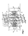
- the preferred embodiment of the present invention comprises a pair of transverse end frame members 10, 12 and a pair of longitudinal frame members 14, 16 which are connected at their ends to the end members 10, 12.
- the frame members 10, 12, 14, 16 may comprise the entire support frame until such members are incorporated into a truck, trailer, or a stationary installation.
- the ends of the frame members 10, 12 are shown connected to side frame members 18, 20 which are shown in broken or phantom lines. In some installations, it is desirable to include these side frame members 18, 20 as a part of the basic frame structure.
- Fig. 3 shows a typical cross sectional shape of the end frame members 10, 12.
- frame member 10 may include a relatively large area web 22 having a right angle flange 24 along one of its sides. The opposite side of web 22 may be welded at 26 to the mid part of a plate member 28.
- end frame 12 may comprise a large area web 30, a right angle flange 32 extending along one side of the web 30, and a plate 34 to which the opposite side of the web 30 is welded.
- Fig. 3 illustrates how neatly this type of frame structure can be incorporated into a bed frame for a truck or trailer.
- the illustrated embodiment comprises three linear hydraulic motors 36, 38, 40. These motors 36, 38, 40 have stationary pistons and traveling cylinder housings 42, 44, 46.
- the piston rods have outer ends which are connected to the plates 28, 34, in a manner that is hereinafter described.
- the cylinder housings 42, 44, 46 travel back and forth on piston heads, as will hereinafter be described. They travel in a space which is defined between the frame plates 28, 34.
- Each linear hydraulic motor 36, 38, 40 drives one third of the floor members.
- Each linear hydrau- ic motor 36, 38, 40 is connected to a separate ransverse drive beam 48, 50, 52.
- Each transverse drive beam 48, 50, 52 carries a plurality of connec-or elements, one for each floor slat member that is connected to it.
- Fig. 1 a portion of the floor slat members are shown in broken or phantom line. Specifically, two epetitions of the members are shown.
- the floor nembers 1 are shown attached to connectors 54 which are in turn connected to transverse drive beam 48.
- Floor members 2 are connected to con- lectors 56 which are in turn connected to trans- terse drive beam 50.
- Floor members 3 are con- hected to connectors 58 which are in turn connected to transverse drive beam 52. This pattern of he floor members is continued across the full width of the installation. As shown by Fig.
- the connector members which are located in the vicinity of the linear hydraulic motors 36, 38, 40 are nade long enough so that they each present end portions outwardly of the ends of the cylinder hous- ngs. These end portions include the apertures which receive the bolts or other connectors used to secure the floor members to the connector ele- nents 54, 56, 58, etc.
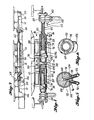
- the linear hydraulic motors 36, 38, 40 are dentical in construction. Accordingly, only one of hese units will be described, it being understood hat the description applies equally as well to the bther two units.
- Cylinder housing 72 travels back and forth on the piston heads 66, 70.
- Cylinder housing 72 includes a transverse center wall 74.
- the cylinder housing 72 may be constructed in two sections, with the inner ends of the sections welded to the wall 74.
- Cylinder housing 72 includes an end member 76, 78 at each of its ends. Each end member 76, 78 includes a central opening through which the adjoining piston rods 60, 62 extend. In Fig. 4, the central opening in end member 78 is designated 80.
- the end members 76, 78 carry oil and dirt seals which seal between it and its piston rod 60, 62.
- a first fluid chamber 82 is formed within cylinder housing 72 between end member 76 and piston head 66.
- a second fluid chamber 84 shown in Fig. 4 in a substantially closed position, is formed within cylinder housing 72 between piston head 66 and divider wall 74.
- a third fluid chamber 86 is defined within cylinder housing 72 between the divider wall 74 and the second piston head 70.
- a fourth fluid chamber 88 is defined within cylinder housing 72 between the piston head 70 and the second end member 78.
- chamber 82 is connected with chamber 86 and chamber 84 is connected with chamber 88.
- This is preferably done by the use of a pair of rigid links of tubing 90, 92.
- Each link of tubing 90, 92 includes a straight central portion and right angle bent end portions.
- Tubing 92 is connected at one end to a side portion of cylinder housing 72 at the location of a port 94.
- the opposite end of tube 90 is connected to a peripheral portion of divider wall 74, at the location of a port 96 (Fig. 5.).
- Tubing 92 is connected at one end to a peripheral portion of the divider wall 74, at the location of a port 98.
- the opposite end is connected to a sidewall portion of the cylinder housing, at the location of a port 100.
- the ends of the tubes 90, 92 are secured in place by welding.
- port 96 is at the outer end of a passageway 102 which extends first radially and then axially.
- the axial portion 104 communicates with chamber 86.
- Port 98 communicates with a passageway 106 which extends first radially and then axially.
- the axial portion 108 communicates with chamber 84.
- a fluid passageway extends lengthwise through piston rod 60, from its outer to its inner end.
- a central passagway 112 extends lengthwise through piston rod 62, from its outer to its inner end.
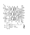
- Fig. 7 is a schematic diagram of the three linear hydraulic motors 36, 38, 40 and other basic parts of the fluid system.
- the system includes a switching circuit 114 which reverses the direction of fluid pressure and flow to and from the opposite ends of the linear hydraulic motors 36, 38, 40.
- the switching circuit is not a part of the invention and may be like the one disclosed in the aforementioned U.S. Patent No. 4,143,760. Accordingly, the details of the circuit are not illustrated.
- Hydraulic pressure and flow is provided by a pump 116.
- the system also includes a return line 118 leading to a storage tank 20.
- ports 122 are provided at the outer ends of the passageways 110. Fluid conduits 124, 126, 128 are interconnected between the switching circuit and these ports 122.
- Linear hydraulic motor 36 includes a port 130 at the outer end of its passageway 112.
- a conduit 132 is interconnected between the switching circuit and this port 130.
- a conduit 134 is interconnected between the passageways 112 of linear hydraulic motors 36, 38.
- a similar passageway 136 is interconnected between the passageways 112 of linear hydraulic motors 38, 40.
- a transfer valve 138 is located in conduit 134.
- a transfer valve 140 is located within conduit 136.
- the switching circuit is operated to send hydraulic pressure and flow via conduit 132 to the port 130.
- the pressure acts to open transfer valves 138, 140 (they act as check valves) so that the fluid pressure and flow is introduced into all three of the passageways 112.
- switching circuit 114 connects the passageways 110 to return pressure.
- the fluid pressure introduced into passageways 112 enters expansible chambers 86 and 82. It enters the chambers 86 first and then flows from chamber 86 through conduits 90 to chambers 82. Introduction of fluid pressure and flow in the chambers 86, 82 causes a movement of all three linear hydraulic motors 36, 38, 40, in unison, from end frame member 12 towards end frame member 10. As they move, the linear hydraulic motors 36, 38, 40 move all of the floor slat members in unison, for advancing the load an amount equal to the stroke of the linear hydraulic motors 36, 38, 40.
- the switching circuit is operated to reverse flow through the conduits 132, 124.
- System pressure is introduced into conduit 124 and conduit 132 is connected to return pressure.
- System pressure from conduit 124 enters into conduit 126 and conduit 128.
- system pressure is introduced into all three of the passageways 110. This pressure is communicated via the passageways 110 to the chambers 84. It is further communicated via the conduits 92 to the chambers 88.
- the chambers 86, 82 of linear hydraulic motor 36 are communicated to the return line 132.
- the transfer valves 138, 140 are closed. They block flow out from linear hydraulic motors 38, 40. There is no valve in return line 132.
- linear hydraulic motor 36 is moved by the introduction of fluid pressure into chambers 84 and 88, while venting chambers 86, 82.
- Linear hydraulic motor 36 moves from end frame 10 towards end frame 12 and moves with it one third of the floor members, i.e. members 1 in Fig. 1.
- linear hydraulic motor 38 When linear hydraulic motor 36 reaches the end of its stroke an abutment 142 carried at the end of the cylinder housing contacts and depresses an operator 144 which opens the transfer valve 138. Upon opening of transfer valve 138, chambers 86 and 82 in linear hydraulic motor 38 are put into communication with the return line 132 via conduit 90, passageway 112, passageway 134 and port 130. Chambers 84 and 88 are still connected to system pressure. Therefore, linear hydraulic motor 38 moves from end frame 10 towards end frame 12, moving with it the floor members to which it is connected, viz. floor members 2 in Fig. 1.
- End piece 68 of piston rod 62 is welded at its outer end to a mounting plate 150.
- Mounting plate 150 is then bolted or otherwise secured to frame member 34.
- Figs. 4 and 13 show the use of nut and bolt assemblies 152, 154 extending through the mounting plate 150 and frame plate 34.
- End piece 68 is formed to include flattened upper and lower surfaces 156, 158. It also includes a side port 160 extending laterally outwardly from fluid passageway 112.
- Transfer valve 140 includes a housing which is suitably attached to the end piece 68.
- Housing 162 includes a first inlet port 164, an outlet port 166 and a second inlet port 168.
- a passageway 170 extends between port 164 and port 166.
- a sidewall of passageway 170 includes an orifice 172 which is normally closed by a valve plug member 174.
- An opening is provided in housing 162 opposite the orifice 172.
- Operator 148 extends through the opening 176, in the manner illustrated.
- Operator 148 includes a central cavity 178 which receives an elongated stem 180.
- Stem 180 is connected at its outer end to the valve plug member 158. It includes a main body portion which is substantially smaller in diameter than the cavity 178. It includes an annular enlarged diameter portion 182 intermediate its length. Portion 182 is only slightly smaller in diameter than the cavity 178.
- An O-ring seal 184 or the like surrounds operator 148 and seals between it and the wall of the opening 176.
- This arrangement of the operator 148, the stem 180, and the valve plug 174 provides a way of isolating the valve plug 174 from any side loads imposed on the operator 148.
- the provision of the enlarged diameter band 182 on the stem 80, and the making of stem 180 in other respects substantially smaller in diameter than the passageway 178, would permit a substantial amount of sideways wiggle of the operator 148 without this motion being transmitted to the valve plug 174.
- valve plug 174 opposite the stem 180 includes a tubular extension 186.
- One end of a spring 188 is received within the tube 186.
- the opposite end of the spring is received within a well formed in a wall of the housing 162.
- Spring 188 serves to normally bias valve plug 174 into a seated position in orifice 172.
- Fig. 14 shows what happens when the abutment 146 carried by the cylinder housing of linear hydraulic motor 38 contacts the operator 148 of transfer valve 140.
- the operator 148 is depressed. It moves inwardly and exerts a force on stem 180, causing it to move inwardly and move with it the valve plug 174.
- Valve plug 174 is unseated from the orifice 172. This allows the portion of conduit 136 that is connected to linear hydraulic motor 40 to be in a fluid transfering communication with the portion of conduit 136 that is connected to linear hydraulic motor 38. This allows a retraction of linear hydraulic motor 40 in the manner described above in connection with the system shown by Fig. 7.
- Transfer valve 140 may be conveniently attached to the end piece 68 of piston rod 62 by means of a pair of clamp plates 190, 192 and four nut and bolt assemblies 194.
- a flat surface of valve housing 162 is placed against the flat surface 158 of end piece 68.
- An O-ring 196 located within an annular groove formed in housing 162 seals against leakage from the region of the ports 160, 162, out from between the housing 162 in end piece 68.
- Clamp plate 190 rests on the flat surface 156 on end piece 68.
- the nut and bolt assembly 194 extends from the corner regions of clamp plate 190 to the corner regions of the clamp plate 192.
- Clamp plate 192 includes a pair of U-shaped recesses for receiving near end portions of U-shaped tubes 196, 198.
- An annular fitting 200 at the end of tube 196 fits against a flat portion of valve housing 162.
- An annular groove formed in this end piece 200 holds an O-ring 202 which seals against leakage between valve housing 192 and end piece 200.
- an end piece 204 at the end of tube 198 fits against the same flat surface of valve housing 162.
- End piece 204 includes an annular groove in which an O-ring 206 is received.
- O-ring 206 seals against leakage between end piece 204 and the valve housing 162.
- the portions of clamp plate 192 bordering the U-shaped recesses in which the tubes 196, 198 are received bears against the end pieces 200, 204, when the nut and bolt assemblies 194 are tightened.
- the system disclosed by Fig. 7 is a one-way drive. That is, it is designed to move all of the floor members in unison, in one direction only, while returning them, one third at a time, in the opposite direction. As a result, a different type of fitting is provided at the opposite ends of the linear hydraulic motors.
- the aforementioned U.S. Patent No. 4,143,760 discloses a two-way or reversible system (see Fig. 4 of that patent).
- the drive assembly of the present invention can also be arranged to provide a reversible or two-way drive. It is only necessary to provide additional valving and conduits, including a pair of transfer valves at the opposite ends of the linear hydraulic motors 38, 40.
- Figs. 15 and 16 show an embodiment of the construction of the opposite ends of the linear hydraulic motors in a one-way system. Again, it is linear hydraulic motor 38 that is being illustrated. However, the end construction of linear hydraulic motors 36, 40 is the same.
- end piece 64 is connected (as by welding) at its outer end to a mounting plate 208. It also includes diameterically opposed flat side surfaces 210, 212.
- a first clamp plate 214 is positioned on the flap 210. End pieces 216, 218 of two separate U-shaped tubes 220, 222, respectively, are positioned against the flat surface 212. These end pieces 216, 218 are constructed like end pieces 202, 204. They include annular grooves into which O-rings are received, for sealing against leakage against the end pieces 216, 218 and the surface 212.
- the second clamp plate 224 is located below the end pieces 216, 218. Like clamp plate 192, it includes a pair of opposed U-shaped recesses in which the end portions of the tubes 220, 222 are received. The portion of clamp plate 224 immediately bordering the recesses bears against the end pieces 216, 218.
- a set of four nut and bolt assemblies 226 are interconnected between the clamp plates 214, 224, and when tightened hold the entire assembly together.
- the end piece 68 at the outer end of the piston rod 112 of linear hydraulic motor 40 may include a fitting of the type shown by Figs 15 and 16, except that only one tube end is secured to the end piece 68.
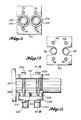
- Fig. 17 is a side elevational view of a U-shaped tube used at the outer ends of the passageway 110.
- Fig. 18 is a side elevational view of a U-shaped tube used between the outer end of the passageway 112 in linear hydraulic motor 40 and the second inlet of the transfer valve 140.
- the linear hydraulic motors are connected to the transverse drive beams by clamps.
- the clamps include an upper clamp member attached to the transverse drive beam.
- the upper clamp member has a lower portion shaped to engage the cylinder housing.
- a lower clamp member is located below the cylinder housing. It has an upper portion shaped to engage the cylinder housing.
- Removable connectors e.g. nut and bolt assemblies
- the cylinder housing in at least one of the clamp members includes interlocking portions which serve to prevent the cylinder housing from moving longitudinally relative to the clamp member. These may be circumferentially extending ribs formed on a member attached to the cylinder housing and complimentary ribs formed on one of the clamp members.
Abstract
Description
- This invention relates to improvements in reciprocating floor conveyors, and in particular to the provision of a smaller size and lighter weight hydraulic drive and support frame assembly.
- Reciprocating floor conveyors are a relatively recent developement. Basically, they comprise at least one group of at least three elongated floor members and a hydraulic drive system which operates to drive at least a majority of the floor members in unison in the desired conveying direction, and to retract them individually. Systems are in use in which all of the floor members are driven in unison, in the desired conveying direction, and are then individually retracted sequentially. It is also been proposed to drive a majority of the floor slat members in the desired conveying direction while at the same time retracting the remaining floor slat members. The present invention has application with both types of systems.
- For background purposes, reference is made to United States Patent No. 4,143,760, granted March 19, 1979; United States Patent No. 4,144,963, granted March 30, 1969; United States Patent No. 4,184,587, granted January 22, 1980; all to Olaf A. Hallstrom. Reference is also made to my United States Patents Nos. 4,474,285; 4,492,303; 4,508,211; 4,580,678; and to my copending application Serial No. 477,767 Reduced Size Drive/Frame Assembly for Reciprocating Floor Conveyor, filed December 11, 1984. Application Serial No. 477,767 was published under the Patent Cooperation Treaty as International Publication No. W084,03686, on September 27, 1984. The system is also prior art by the fact of its commercial sale and use.
- Earlier forms of reciprocating floor conveyors are disclosed by United States Patent No. 2,629,504, granted in February of 1953 to Peter- son; by United States Patent No. 2,973,856, granted in March of 1961 to Brooks; by United States Patent No. 3,534,875, granted in October of 1970 to Hallstrom; by United States Patent No. 3,905,290, granted September 16, 1975 to Robert A. Caughey; and by West German Patent Publication No. 1,296,087, published in May of 1969. These patents are not particularly pertinent to the subject invention and require no further comment.
- The present invention provides a relatively small and light weight modular type drive assembly.
- The drive assembly of the present invention is basically characterized by a plurality of reversible linear hydraulic drive units, one for each set of floor slat members. Each drive unit comprises a pair of piston rods, each of which is mounted at its outer end to a frame and each of which carries a piston head at its inner end, and a cylinder housing mounted to reciprocate back and forth on the piston heads. When installed, the piston rods are fixed and the cylinder housings are movable. A transverse drive beam is associated with each cylinder housing. Each transverse drive beam is connected to its set of floor slat members and is also connected to the moving cylinder housing of its hydraulic drive unit.
- The cylinder housing includes an end member at each of its ends. Each end member includes a central opening through which the piston rod at such end extends. The cylinder housing further includes a divider wall between its ends. A first fluid chamber is formed within the cylinder housing between a first end member and a first piston head. A second fluid chamber is formed within the cylinder housing between the first piston head and the divider wall. A third fluid chamber is formed within said cylinder housing between said divider wall and the second piston head. A fourth fluid chamber is formed within the cylinder housing between the second piston head and the second end member.
- The divider wall includes a first passageway having an inner end communicating with said third chamber and an outer end. The divider wall also includes a second passageway having an inner end communicating with the second chamber, and an outer end. A first conduit means extends through the first piston rod. It includes an inner end in communication with the second chamber, and an outer end. A second conduit is interconnected between the first chamber and the outer end of the first passageway in the divider wall. A third conduit means is interconnected between the outer end of the second passageway and the divider wall and the fourth chamber. A fourth conduit means extends through the second piston rod and has an inner end in communication with the third fluid chamber, and an outer end.
- In preferred form, each piston rod has a mounting pad at its outer end. The outer end of the first conduit means opens laterally of the first piston rod, at a location spaced inwardly from the mounting pad. The outer end of the fourth conduit means opens laterally from the second piston rod, at a location spaced inwardly from the second mounting pad.
- In preferred construction, the cylinder housing is constructed in two sections, each with an inner end. The divider wall is a member between the two sections, to which the inner ends of the two sections are joined.
- In preferred form, the second and third conduit means are sections of rigid tubing welded at their ends to the cylinder housing.
- The construction of the piston rod in two parts, and the division of the cylinder housing into four chambers, connected together in pairs, results in a hydraulic unit which is relatively small and light weight, and strong, for the amount of force which it can produce. The tubular construction of the piston rods increases their strength in comparison to solid rods. The interconnection of the first and third chambers and the interconnection of the second and fourth chambers makes it possible to use a reduced diameter drive unit while still maintaining a substantial area against which the hydraulic fluid can act, for moving the cylinder housing in either direction. In each direction of travel the effective area is the area of the divider wall plus the area of the inner end of one of the end members.
- The use of the piston rods as fluid passageways makes it possible to greatly simplify the plumbing together of a plurality of the drive units to form the drive assembly. It allows the use of short rigid tubes at the outer ends of the piston rods, and an easy to assemble and disassemble manner of connecting the tubes to the piston rod.
- In accordance with an aspect of the invention, transfer valves are attached to end portions of some of the piston rods. The transfer valve of the invention is characterized by a housing having a first inlet in communication with the outer end of the fluid passageway in the piston rod, an outlet and a through passageway extending from the first inlet to the outlet. A transfer port is provided in a side portion of the passageway, between the first inlet and the outlet. The transfer port has a first side directed toward said passageway and an opposite second side. A valve plug member is provided on the second side of the transfer port. Spring means normally biases the valve plug member into a seated position against the second side of the transfer port. The housing is provided with an opening that is spaced across the passageway from the transfer port. An operator means, connected to the valve plug, extends from the valve plug to and through the opening in the housing. The operator means extends substantially parallel to the piston rod. It has an outer portion which projects outwardly beyond the opening in the housing. The housing also includes a second inlet for fluid delivery to and from the second side of the transfer port. The cylinder housing is provided with an abutment means positioned to contact the outer portion of the operator and move the operator endwise, against the biasing force of the spring means, to move the valve plug away from the transfer port. This allows fluid to flow from the second inlet, through the transfer port, and into and through the passageway to and out from the outlet. When fluid flow is reversed, i.e. the outlet is connected to system pressure and the second inlet is connected to return pressure, the system pressure acts on the valve plug, moving it in opposition to the spring force, to open the transfer port.
- In accordance with an aspect of the invention, an end member of a first conduit is placed against the outlet of the housing. A similar end member of a second conduit is placed against the second inlet portion of the housing. A first clamp member is positioned to bear against both of said end members. A second clamp member is positioned against the outer end portion of the piston rod, on the side of the piston rod opposite the transfer valve housing. A plurality of nut and bolt assemblies are interconnected between the two clamp members, for clamping the transfer valve to the end portion of the piston rod.
- Other more detailed features of the invention are hereinafter described as a part of the description of the best mode of the invention.
- Like reference numerals are used to designate like parts throughout the several views of the drawing, and:
- Fig. 1 is a top plan view of a hydraulic drive assembly for use in a reciprocating floor conveyor, with some floor members shown in broken line, with the floor member support and guide system omitted, and with some frame members being shown in broken line;
- Fig. 2 is a bottom plan view of the assembly shown by Fig. 1;
- Fig. 3 is an end elevational view of the drive assembly shown by Figs. 1 and 2;
- Fig. 4 is an enlarged scale sectional view, taken substantially along
line 4--4 of Fig. 1, with some parts being shown in elevation; - Fig. 5 is a sectional view taken substantially along line 5--5 of Fig. 4;
- Fig. 6 is a sectional view taken substantially along line 6--6 of Fig. 4;
- Fig. 7 is a system diagram;
- Fig. 8 is a side elevational view of the transfer valve assembly shown by Fig. 7;
- Fig. 9 is a top plan view of the transfer valve assembly, taken substantially along
line 19--19 of Fig. 8; - Fig. 10 is a sectional view taken substantially along
line 10--10 of Fig. 8; - Fig. 11 is a sectional view taken substantially along
line 11--11 of Fig. 8. - Fig. 12 is a sectional view taken substantially along
line 12--12 of Fig. 8; - Fig. 13 is an enlarged scale, fragmentary sectional view taken through a transfer valve assembly and one end of a linear hydraulic drive unit, showing the transfer valve in a closed position;
- Fig. 14 is a fragmentary view, on yet a larger scale, of a portion of Fig. 13, showing the transfer valve in an open position;
- Fig. 15 is a side elevational view of an end portion of a linear hydraulic drive unit which does not include a transfer valve;
- Fig. 16 is a sectional view taken substantially along
line 16--16 of Fig. 15; - Fig. 17 is a side elevational view of a first U-tube; and
- Fig. 18 is a side elevational view of a second U-tube.
- Referring to Figs. 1 and 2, the preferred embodiment of the present invention comprises a pair of transverse
end frame members longitudinal frame members end members frame members frame members side frame members side frame members end frame members frame member 10 may include a relativelylarge area web 22 having aright angle flange 24 along one of its sides. The opposite side ofweb 22 may be welded at 26 to the mid part of aplate member 28. In similar fashion,end frame 12 may comprise alarge area web 30, aright angle flange 32 extending along one side of theweb 30, and aplate 34 to which the opposite side of theweb 30 is welded. Fig. 3 illustrates how neatly this type of frame structure can be incorporated into a bed frame for a truck or trailer. - The illustrated embodiment comprises three linear
hydraulic motors motors cylinder housings plates cylinder housings frame plates - Each linear
hydraulic motor ic motor ransverse drive beam transverse drive beam - In Fig. 1 a portion of the floor slat members are shown in broken or phantom line. Specifically, two epetitions of the members are shown. The floor nembers 1 are shown attached to
connectors 54 which are in turn connected totransverse drive beam 48.Floor members 2 are connected to con-lectors 56 which are in turn connected to trans-terse drive beam 50. Floor members 3 are con- hected toconnectors 58 which are in turn connected totransverse drive beam 52. This pattern of he floor members is continued across the full width of the installation. As shown by Fig. 1, the connector members which are located in the vicinity of the linearhydraulic motors nents - The linear
hydraulic motors - Linear
hydraulic motor 38 will now be described, with reference to Figs. 4 and 5: - The
motor 38 includes first and second piston ods 60, 62.Piston rod 60 has inner and outer ends. Itsouter end 64 is mounted and a piston lead 66 is located at its inner end.Piston rod 62 also has inner and outer ends. Itsouter end 68 is nounted and it includes apiston head 70 at its nner ends. In a manner to be hereinafter described, the outer ends 64, 68 of thepiston rods frame plate members plate members end frame members end frame members longitudinal frame members end frame nembers - Returning to Fig. 4, the described manner of nounting the
piston rods - The
cylinder housing 72 travels back and forth on the piston heads 66, 70.Cylinder housing 72 includes atransverse center wall 74. Thecylinder housing 72 may be constructed in two sections, with the inner ends of the sections welded to thewall 74. -
Cylinder housing 72 includes anend member 76, 78 at each of its ends. Eachend member 76, 78 includes a central opening through which the adjoiningpiston rods end member 78 is designated 80. Theend members 76, 78 carry oil and dirt seals which seal between it and itspiston rod - A
first fluid chamber 82 is formed withincylinder housing 72 between end member 76 and piston head 66. Asecond fluid chamber 84, shown in Fig. 4 in a substantially closed position, is formed withincylinder housing 72 between piston head 66 anddivider wall 74. Athird fluid chamber 86 is defined withincylinder housing 72 between thedivider wall 74 and thesecond piston head 70. Afourth fluid chamber 88 is defined withincylinder housing 72 between thepiston head 70 and thesecond end member 78. - In accordance with an aspect of the invention,
chamber 82 is connected withchamber 86 andchamber 84 is connected withchamber 88. This is preferably done by the use of a pair of rigid links oftubing tubing Tubing 92 is connected at one end to a side portion ofcylinder housing 72 at the location of a port 94. The opposite end oftube 90 is connected to a peripheral portion ofdivider wall 74, at the location of a port 96 (Fig. 5.).Tubing 92 is connected at one end to a peripheral portion of thedivider wall 74, at the location of aport 98. The opposite end is connected to a sidewall portion of the cylinder housing, at the location of aport 100. Preferably, the ends of thetubes - Referring to Fig. 5,
port 96 is at the outer end of a passageway 102 which extends first radially and then axially. Theaxial portion 104 communicates withchamber 86.Port 98 communicates with apassageway 106 which extends first radially and then axially. Theaxial portion 108 communicates withchamber 84. - A fluid passageway extends lengthwise through
piston rod 60, from its outer to its inner end. In like fashion, acentral passagway 112 extends lengthwise throughpiston rod 62, from its outer to its inner end. As will hereinafter be described in more detail, there is fluid flow throughpassageway 110 into and out fromchamber 84. There is fluid flow throughpassageway 112 into and out fromchamber 86. - Fig. 7 is a schematic diagram of the three linear
hydraulic motors - The system includes a
switching circuit 114 which reverses the direction of fluid pressure and flow to and from the opposite ends of the linearhydraulic motors pump 116. The system also includes areturn line 118 leading to astorage tank 20. At one end of the drive assembly,ports 122 are provided at the outer ends of thepassageways 110.Fluid conduits ports 122. Linearhydraulic motor 36 includes aport 130 at the outer end of itspassageway 112. Aconduit 132 is interconnected between the switching circuit and thisport 130. Aconduit 134 is interconnected between thepassageways 112 of linearhydraulic motors similar passageway 136 is interconnected between thepassageways 112 of linearhydraulic motors transfer valve 138 is located inconduit 134. Atransfer valve 140 is located withinconduit 136. - In the course of operation of the system, the switching circuit is operated to send hydraulic pressure and flow via
conduit 132 to theport 130. The pressure acts to opentransfer valves 138, 140 (they act as check valves) so that the fluid pressure and flow is introduced into all three of thepassageways 112. At the same time, switchingcircuit 114 connects thepassageways 110 to return pressure. - The fluid pressure introduced into
passageways 112 entersexpansible chambers chambers 86 first and then flows fromchamber 86 throughconduits 90 tochambers 82. Introduction of fluid pressure and flow in thechambers hydraulic motors end frame member 12 towardsend frame member 10. As they move, the linearhydraulic motors hydraulic motors - At the end of the stroke, the switching circuit is operated to reverse flow through the
conduits conduit 124 andconduit 132 is connected to return pressure. System pressure fromconduit 124 enters into conduit 126 andconduit 128. Thus, system pressure is introduced into all three of thepassageways 110. This pressure is communicated via thepassageways 110 to thechambers 84. It is further communicated via theconduits 92 to thechambers 88. Thechambers hydraulic motor 36 are communicated to thereturn line 132. However, at the start of this cycle, thetransfer valves hydraulic motors return line 132. Therefore, linearhydraulic motor 36 is moved by the introduction of fluid pressure intochambers chambers hydraulic motor 36 moves fromend frame 10 towardsend frame 12 and moves with it one third of the floor members, i.e. members 1 in Fig. 1. - When linear
hydraulic motor 36 reaches the end of its stroke an abutment 142 carried at the end of the cylinder housing contacts and depresses an operator 144 which opens thetransfer valve 138. Upon opening oftransfer valve 138,chambers hydraulic motor 38 are put into communication with thereturn line 132 viaconduit 90,passageway 112,passageway 134 andport 130.Chambers hydraulic motor 38 moves fromend frame 10 towardsend frame 12, moving with it the floor members to which it is connected, viz.floor members 2 in Fig. 1. - When linear
hydraulic motor 38 approaches the end of its stroke anabutment 146 carried at the end of its cylinder housing makes contact with, and depresses, anoperator 148 which openstransfer valve 140. As soon astransfer valve 140 is opened thechambers hydraulic motor 40 are put into communication with thereturn line 132.Chambers transfer valve 140, linearhydraulic motor 40 moves fromend frame 10 towardsend frame 12, moving with it the floor members to which it is attached, viz. floor members 3 in Fig. 1. When linearhydraulic motor 40 reaches the end of its stroke it triggers the switching valve, to again reverse the direction of pressure and flow to theconduits -
Transfer valve 140 will now be described, with reference to Figs. 8-14. -
End piece 68 ofpiston rod 62 is welded at its outer end to a mountingplate 150. Mountingplate 150 is then bolted or otherwise secured to framemember 34. Figs. 4 and 13 show the use of nut andbolt assemblies plate 150 andframe plate 34.End piece 68 is formed to include flattened upper andlower surfaces side port 160 extending laterally outwardly fromfluid passageway 112.Transfer valve 140 includes a housing which is suitably attached to theend piece 68.Housing 162 includes afirst inlet port 164, anoutlet port 166 and asecond inlet port 168. Apassageway 170 extends betweenport 164 andport 166. A sidewall ofpassageway 170 includes anorifice 172 which is normally closed by avalve plug member 174. An opening is provided inhousing 162 opposite theorifice 172.Operator 148 extends through theopening 176, in the manner illustrated.Operator 148 includes acentral cavity 178 which receives anelongated stem 180.Stem 180 is connected at its outer end to thevalve plug member 158. It includes a main body portion which is substantially smaller in diameter than thecavity 178. It includes an annularenlarged diameter portion 182 intermediate its length.Portion 182 is only slightly smaller in diameter than thecavity 178. An O-ring seal 184 or the like surroundsoperator 148 and seals between it and the wall of theopening 176. This arrangement of theoperator 148, thestem 180, and thevalve plug 174 provides a way of isolating thevalve plug 174 from any side loads imposed on theoperator 148. In other words, the provision of theenlarged diameter band 182 on thestem 80, and the making ofstem 180 in other respects substantially smaller in diameter than thepassageway 178, would permit a substantial amount of sideways wiggle of theoperator 148 without this motion being transmitted to thevalve plug 174. - The end of
valve plug 174 opposite thestem 180 includes atubular extension 186. One end of aspring 188 is received within thetube 186. The opposite end of the spring is received within a well formed in a wall of thehousing 162.Spring 188 serves to normally biasvalve plug 174 into a seated position inorifice 172. - Fig. 14 shows what happens when the
abutment 146 carried by the cylinder housing of linearhydraulic motor 38 contacts theoperator 148 oftransfer valve 140. Theoperator 148 is depressed. It moves inwardly and exerts a force onstem 180, causing it to move inwardly and move with it thevalve plug 174.Valve plug 174 is unseated from theorifice 172. This allows the portion ofconduit 136 that is connected to linearhydraulic motor 40 to be in a fluid transfering communication with the portion ofconduit 136 that is connected to linearhydraulic motor 38. This allows a retraction of linearhydraulic motor 40 in the manner described above in connection with the system shown by Fig. 7. -
Transfer valve 140 may be conveniently attached to theend piece 68 ofpiston rod 62 by means of a pair ofclamp plates bolt assemblies 194. A flat surface ofvalve housing 162 is placed against theflat surface 158 ofend piece 68. An O-ring 196 located within an annular groove formed inhousing 162 seals against leakage from the region of theports housing 162 inend piece 68.Clamp plate 190 rests on theflat surface 156 onend piece 68. The nut andbolt assembly 194 extends from the corner regions ofclamp plate 190 to the corner regions of theclamp plate 192.Clamp plate 192 includes a pair of U-shaped recesses for receiving near end portions ofU-shaped tubes annular fitting 200 at the end oftube 196 fits against a flat portion ofvalve housing 162. An annular groove formed in thisend piece 200 holds an O-ring 202 which seals against leakage betweenvalve housing 192 andend piece 200. In similar fashion, anend piece 204 at the end oftube 198 fits against the same flat surface ofvalve housing 162.End piece 204 includes an annular groove in which an O-ring 206 is received. O-ring 206 seals against leakage betweenend piece 204 and thevalve housing 162. The portions ofclamp plate 192 bordering the U-shaped recesses in which thetubes end pieces bolt assemblies 194 are tightened. As can be appreciated, the above-described construction of the transfer valve, and the manner of its connection to the end piece, make assembly and disassembly quite easy. - The system disclosed by Fig. 7 is a one-way drive. That is, it is designed to move all of the floor members in unison, in one direction only, while returning them, one third at a time, in the opposite direction. As a result, a different type of fitting is provided at the opposite ends of the linear hydraulic motors. The aforementioned U.S. Patent No. 4,143,760 discloses a two-way or reversible system (see Fig. 4 of that patent). The drive assembly of the present invention can also be arranged to provide a reversible or two-way drive. It is only necessary to provide additional valving and conduits, including a pair of transfer valves at the opposite ends of the linear
hydraulic motors - Figs. 15 and 16 show an embodiment of the construction of the opposite ends of the linear hydraulic motors in a one-way system. Again, it is linear
hydraulic motor 38 that is being illustrated. However, the end construction of linearhydraulic motors - Referring to Figs. 15 and 16,
end piece 64 is connected (as by welding) at its outer end to a mountingplate 208. It also includes diameterically opposed flat side surfaces 210, 212. - A
first clamp plate 214 is positioned on theflap 210.End pieces U-shaped tubes flat surface 212. Theseend pieces end pieces end pieces surface 212. Thesecond clamp plate 224 is located below theend pieces clamp plate 192, it includes a pair of opposed U-shaped recesses in which the end portions of thetubes clamp plate 224 immediately bordering the recesses bears against theend pieces bolt assemblies 226 are interconnected between theclamp plates - The
end piece 68 at the outer end of thepiston rod 112 of linearhydraulic motor 40 may include a fitting of the type shown by Figs 15 and 16, except that only one tube end is secured to theend piece 68. - Fig. 17 is a side elevational view of a U-shaped tube used at the outer ends of the
passageway 110. Fig. 18 is a side elevational view of a U-shaped tube used between the outer end of thepassageway 112 in linearhydraulic motor 40 and the second inlet of thetransfer valve 140. - In preferred form, the linear hydraulic motors are connected to the transverse drive beams by clamps. The clamps include an upper clamp member attached to the transverse drive beam. The upper clamp member has a lower portion shaped to engage the cylinder housing. A lower clamp member is located below the cylinder housing. It has an upper portion shaped to engage the cylinder housing. Removable connectors (e.g. nut and bolt assemblies) are provided for detachably securing the two clamp members together. Preferably also, the cylinder housing in at least one of the clamp members includes interlocking portions which serve to prevent the cylinder housing from moving longitudinally relative to the clamp member. These may be circumferentially extending ribs formed on a member attached to the cylinder housing and complimentary ribs formed on one of the clamp members. Reference is made to my copending application Serial No. 477,767 for a more detailed showing and description of this manner of connecting the transverse drive beams to the cylinder housings. The contents of Serial No. 477,767 is hereby incorporated into this application by this specific reference.
- The embodiment that has been illustrated and described is merely an example of the invention. The protection is not to be determined by such embodiment, but only by a proper interpretation of the following claims, including a use of the doctrine of equivalents.
Claims (5)
Applications Claiming Priority (3)
| Application Number | Priority Date | Filing Date | Title |
|---|---|---|---|
| US06/905,370 US4821868A (en) | 1986-09-08 | 1986-09-08 | Drive/frame assembly for a reciprocating floor |
| US905370 | 1986-09-08 | ||
| EP87201280A EP0259901B1 (en) | 1986-09-08 | 1987-07-03 | Drive/frame assembly for a reciprocating floor |
Related Parent Applications (1)
| Application Number | Title | Priority Date | Filing Date |
|---|---|---|---|
| EP87201280.2 Division | 1987-07-03 |
Publications (2)
| Publication Number | Publication Date |
|---|---|
| EP0468602A1 true EP0468602A1 (en) | 1992-01-29 |
| EP0468602B1 EP0468602B1 (en) | 1995-03-01 |
Family
ID=25420709
Family Applications (2)
| Application Number | Title | Priority Date | Filing Date |
|---|---|---|---|
| EP87201280A Expired - Lifetime EP0259901B1 (en) | 1986-09-08 | 1987-07-03 | Drive/frame assembly for a reciprocating floor |
| EP91202508A Expired - Lifetime EP0468602B1 (en) | 1986-09-08 | 1987-07-03 | Drive/frame assembly for a reciprocating floor |
Family Applications Before (1)
| Application Number | Title | Priority Date | Filing Date |
|---|---|---|---|
| EP87201280A Expired - Lifetime EP0259901B1 (en) | 1986-09-08 | 1987-07-03 | Drive/frame assembly for a reciprocating floor |
Country Status (7)
| Country | Link |
|---|---|
| US (1) | US4821868A (en) |
| EP (2) | EP0259901B1 (en) |
| JP (1) | JP2609251B2 (en) |
| AT (2) | ATE119242T1 (en) |
| CA (1) | CA1315646C (en) |
| DE (2) | DE3751120T2 (en) |
| ES (2) | ES2068489T3 (en) |
Cited By (1)
| Publication number | Priority date | Publication date | Assignee | Title |
|---|---|---|---|---|
| EP0934892A1 (en) * | 1998-02-06 | 1999-08-11 | Richard T. Gist | Fluid drive for reciprocating floor |
Families Citing this family (26)
| Publication number | Priority date | Publication date | Assignee | Title |
|---|---|---|---|---|
| US4969389A (en) * | 1988-05-03 | 1990-11-13 | Foster Raymond K | Multisection hydraulic drive unit with single piston rod |
| US4984679A (en) * | 1990-03-23 | 1991-01-15 | Foster Raymond K | Seal between reciprocating conveyor floor members |
| US5088595A (en) * | 1990-12-17 | 1992-02-18 | Hallstrom Jr Olof A | Waterproof reciprocating conveyor |
| US5096356A (en) * | 1991-04-08 | 1992-03-17 | Foster Raymond K | Reciprocating floor conveyor in a receptacle for a liquid laden material |
| US5193661A (en) * | 1992-02-05 | 1993-03-16 | Foster Raymond K | System of linear hydraulic motors |
| US5383548A (en) * | 1992-04-27 | 1995-01-24 | Quaeck; Manfred W. | Reciprocating floor conveyor |
| US5340264A (en) * | 1992-04-27 | 1994-08-23 | Quaeck Manfred W | Reciprocating floor conveyor |
| US5301798A (en) * | 1993-03-08 | 1994-04-12 | Wilkens Arthur L | Reciprocating floor conveyor for caustic materials |
| US5390781A (en) * | 1993-04-28 | 1995-02-21 | Foster; Raymond K. | Mounting assembly and method for reciprocating slat conveyor |
| US5325763A (en) * | 1993-04-28 | 1994-07-05 | Foster Raymond K | Internal check valve |
| US5350054A (en) * | 1993-04-28 | 1994-09-27 | Foster Raymond K | Ball block for mounting linear motor |
| US5355995A (en) * | 1993-10-14 | 1994-10-18 | Foster Raymond K | Reciprocating floor conveyor having separable floor and drive portions |
| US5419426A (en) * | 1993-11-16 | 1995-05-30 | Foster; Raymond K. | Snap-in conveyor slat wear plate |
| US5355994A (en) * | 1993-11-16 | 1994-10-18 | Foster Raymond K | Replaceable wear surface for conveyor slats |
| US5373777A (en) * | 1993-12-03 | 1994-12-20 | Foster; Raymond K. | Linear hydraulic motor with snubber |
| US5489018A (en) * | 1993-12-09 | 1996-02-06 | Foster; Raymond K. | Stem for mounting reciprocating slat conveyor |
| US5839568A (en) * | 1994-02-07 | 1998-11-24 | Clark; Gary R. | Reciprocating floor conveyor control system |
| US5402878A (en) * | 1994-04-06 | 1995-04-04 | Lutz; David E. | Reciprocating slat conveyor |
| US5431087A (en) * | 1994-06-15 | 1995-07-11 | Kambara; Goro | Extended stroke linear actuator assembly |
| DE69505058T2 (en) | 1994-07-07 | 1999-02-18 | Raymond Keith Foster | Interchangeable wear surface for slats of a shuttle conveyor |
| US5427229A (en) | 1994-09-20 | 1995-06-27 | Foster; Raymond K. | Control system for reciprocating floor conveyor |
| US5911555A (en) * | 1998-05-12 | 1999-06-15 | Foster; Raymond Keith | Vehicle/dock loading/unloading conveyor system |
| US6065923A (en) * | 1998-05-12 | 2000-05-23 | Foster; Raymond Keith | Vehicle/dock alignment system |
| US6003660A (en) * | 1999-03-24 | 1999-12-21 | Foster; Raymond Keith | Drive units and drive assembly for a reciprocating slat conveyors |
| DE602004005573T2 (en) * | 2003-01-30 | 2007-12-13 | Rene Wegkamp | Hydraulic linear motor and reciprocating floor conveyor |
| JP5412740B2 (en) * | 2008-03-26 | 2014-02-12 | オムロンヘルスケア株式会社 | Blood pressure measurement device |
Citations (3)
| Publication number | Priority date | Publication date | Assignee | Title |
|---|---|---|---|---|
| DE1077145B (en) * | 1955-04-30 | 1960-03-03 | Buss Ag | Hydraulic displacement device for systems for storing piece goods, in particular for parking automobiles |
| US4143760A (en) * | 1975-01-10 | 1979-03-13 | Hallstrom Olof A | Reciprocating conveyor |
| WO1984003686A1 (en) * | 1983-03-22 | 1984-09-27 | Raymond Keith Foster | Reduced size drive/frame assembly for a reciprocating floor conveyor |
Family Cites Families (18)
| Publication number | Priority date | Publication date | Assignee | Title |
|---|---|---|---|---|
| US1977696A (en) * | 1934-01-10 | 1934-10-23 | Western Electric Co | Article conveying apparatus |
| US2550925A (en) * | 1948-06-10 | 1951-05-01 | Brown & Sharpe Mfg | Means for blocking the bore of a long hollow piston rod |
| US2629504A (en) * | 1950-03-02 | 1953-02-24 | Int Harvester Co | Reciprocating floor bottom for unloading vehicles |
| US2973856A (en) * | 1958-04-09 | 1961-03-07 | Prec Scient Company | Conveyor |
| NL6706657A (en) * | 1967-05-12 | 1968-11-13 | ||
| US3534875A (en) * | 1968-11-18 | 1970-10-20 | Olof A Hallstrom Jr | Reciprocating conveyor |
| US3783620A (en) * | 1971-09-03 | 1974-01-08 | J Moe | Synchronizer for hydraulic cylinders |
| US3795176A (en) * | 1971-10-26 | 1974-03-05 | Pettibone Corp | Boom-crowd cylinders with selective sequencing by solenoid valve |
| US3905290A (en) * | 1972-12-21 | 1975-09-16 | Robert A Caughey | Self-feeding press for producing strip material |
| US4144963A (en) * | 1974-08-12 | 1979-03-20 | Hallstrom Olof A | Reciprocating conveyor |
| US4184587A (en) * | 1976-05-27 | 1980-01-22 | Hallstrom Olof A | Reciprocating conveyor and modular drive unit therefor |
| DE2712449A1 (en) * | 1977-03-22 | 1978-09-28 | Daimler Benz Ag | Hydrostatic coupling rod with two pistons in common cylinder - uses adjustable rod length with varying relative piston positions |
| DE2720676C3 (en) * | 1977-05-07 | 1980-08-14 | Helmut 4030 Ratingen Haegermann | Device for stamping leading material such as slabs, billets, finished profiles in rolling mills or continuous casting plants |
| US4492303A (en) * | 1982-02-08 | 1985-01-08 | Foster Raymond K | Drive/guide system for a reciprocating floor conveyor |
| US4508211A (en) * | 1982-02-08 | 1985-04-02 | Foster R Keith | Reciprocating floor conveyor apparatus and method |
| US4474285A (en) * | 1982-02-08 | 1984-10-02 | Foster Raymond K | Drive unit mount for reciprocating floor conveyor |
| US4580678A (en) * | 1984-12-11 | 1986-04-08 | Foster Raymond K | Reciprocating floor conveyor system |
| US4712467A (en) * | 1986-09-08 | 1987-12-15 | Foster Raymond K | Combined linear hydraulic motor and transfer valve |
-
1986
- 1986-09-08 US US06/905,370 patent/US4821868A/en not_active Expired - Lifetime
-
1987
- 1987-07-03 AT AT91202508T patent/ATE119242T1/en not_active IP Right Cessation
- 1987-07-03 AT AT87201280T patent/ATE81328T1/en not_active IP Right Cessation
- 1987-07-03 ES ES91202508T patent/ES2068489T3/en not_active Expired - Lifetime
- 1987-07-03 EP EP87201280A patent/EP0259901B1/en not_active Expired - Lifetime
- 1987-07-03 EP EP91202508A patent/EP0468602B1/en not_active Expired - Lifetime
- 1987-07-03 DE DE3751120T patent/DE3751120T2/en not_active Expired - Lifetime
- 1987-07-03 ES ES198787201280T patent/ES2035851T3/en not_active Expired - Lifetime
- 1987-07-03 DE DE8787201280T patent/DE3782129T2/en not_active Expired - Lifetime
- 1987-07-17 JP JP62178337A patent/JP2609251B2/en not_active Expired - Fee Related
- 1987-09-04 CA CA000546167A patent/CA1315646C/en not_active Expired - Lifetime
Patent Citations (4)
| Publication number | Priority date | Publication date | Assignee | Title |
|---|---|---|---|---|
| DE1077145B (en) * | 1955-04-30 | 1960-03-03 | Buss Ag | Hydraulic displacement device for systems for storing piece goods, in particular for parking automobiles |
| US4143760A (en) * | 1975-01-10 | 1979-03-13 | Hallstrom Olof A | Reciprocating conveyor |
| US4143760B1 (en) * | 1975-01-10 | 1991-02-05 | A Hallstrom Olof | |
| WO1984003686A1 (en) * | 1983-03-22 | 1984-09-27 | Raymond Keith Foster | Reduced size drive/frame assembly for a reciprocating floor conveyor |
Non-Patent Citations (1)
| Title |
|---|
| MACHINE DESIGN. vol. 34, no. 26, 8 November 1962, CLEVELAND US pages 172 - 174; M.E. LONG: 'sequence valves' * |
Cited By (2)
| Publication number | Priority date | Publication date | Assignee | Title |
|---|---|---|---|---|
| EP0934892A1 (en) * | 1998-02-06 | 1999-08-11 | Richard T. Gist | Fluid drive for reciprocating floor |
| AU739202B2 (en) * | 1998-02-06 | 2001-10-04 | Richard T Gist | Fluid drive for reciprocating floor |
Also Published As
| Publication number | Publication date |
|---|---|
| ATE81328T1 (en) | 1992-10-15 |
| ATE119242T1 (en) | 1995-03-15 |
| CA1315646C (en) | 1993-04-06 |
| DE3751120D1 (en) | 1995-04-06 |
| JP2609251B2 (en) | 1997-05-14 |
| ES2068489T3 (en) | 1995-04-16 |
| EP0259901A3 (en) | 1989-02-08 |
| JPS6371013A (en) | 1988-03-31 |
| EP0468602B1 (en) | 1995-03-01 |
| DE3782129D1 (en) | 1992-11-12 |
| DE3751120T2 (en) | 1995-06-22 |
| EP0259901A2 (en) | 1988-03-16 |
| DE3782129T2 (en) | 1993-03-25 |
| ES2035851T3 (en) | 1993-05-01 |
| EP0259901B1 (en) | 1992-10-07 |
| US4821868A (en) | 1989-04-18 |
Similar Documents
| Publication | Publication Date | Title |
|---|---|---|
| EP0259901B1 (en) | Drive/frame assembly for a reciprocating floor | |
| US4748893A (en) | Drive/frame assembly for a reciprocating floor | |
| US4748894A (en) | Drive/frame assembly for a reciprocating floor | |
| EP0259900B1 (en) | Combined linear hydraulic motor and transfer valve | |
| US4793469A (en) | Reduced size drive/frame assembly for a reciprocating floor conveyor | |
| US4962848A (en) | Reciprocating floor conveyor | |
| EP0657372B1 (en) | Mounting assembly for reciprocating slat conveyor | |
| US5984076A (en) | Drive assembly for reciprocating slat conveyor | |
| US4817783A (en) | Single piston rod hydraulic drive | |
| US5638943A (en) | Drive assembly for reciprocating slat conveyor | |
| AU613184B2 (en) | Hydraulic drive with single piston rod | |
| US7380652B2 (en) | Reciprocating slat conveyor | |
| EP0728688B1 (en) | System for mounting reciprocating slat conveyor | |
| US7584838B2 (en) | Linear hydraulic motor and a reciprocating floor conveyor | |
| JPH0362606B2 (en) | ||
| JP2972612B2 (en) | Reciprocating slat conveyor | |
| US20080264764A1 (en) | Drive Beam |
Legal Events
| Date | Code | Title | Description |
|---|---|---|---|
| PUAI | Public reference made under article 153(3) epc to a published international application that has entered the european phase |
Free format text: ORIGINAL CODE: 0009012 |
|
| 17P | Request for examination filed |
Effective date: 19910925 |
|
| AC | Divisional application: reference to earlier application |
Ref document number: 259901 Country of ref document: EP |
|
| AK | Designated contracting states |
Kind code of ref document: A1 Designated state(s): AT BE CH DE ES FR GB GR IT LI LU NL SE |
|
| 17Q | First examination report despatched |
Effective date: 19931125 |
|
| GRAA | (expected) grant |
Free format text: ORIGINAL CODE: 0009210 |
|
| ITF | It: translation for a ep patent filed |
Owner name: STUDIO INGG. FISCHETTI & WEBER |
|
| AC | Divisional application: reference to earlier application |
Ref document number: 259901 Country of ref document: EP |
|
| AK | Designated contracting states |
Kind code of ref document: B1 Designated state(s): AT BE CH DE ES FR GB GR IT LI LU NL SE |
|
| PG25 | Lapsed in a contracting state [announced via postgrant information from national office to epo] |
Ref country code: LI Effective date: 19950301 Ref country code: CH Effective date: 19950301 |
|
| REF | Corresponds to: |
Ref document number: 119242 Country of ref document: AT Date of ref document: 19950315 Kind code of ref document: T |
|
| REF | Corresponds to: |
Ref document number: 3751120 Country of ref document: DE Date of ref document: 19950406 |
|
| REG | Reference to a national code |
Ref country code: ES Ref legal event code: FG2A Ref document number: 2068489 Country of ref document: ES Kind code of ref document: T3 |
|
| ET | Fr: translation filed | ||
| REG | Reference to a national code |
Ref country code: CH Ref legal event code: PL |
|
| PG25 | Lapsed in a contracting state [announced via postgrant information from national office to epo] |
Ref country code: LU Free format text: LAPSE BECAUSE OF NON-PAYMENT OF DUE FEES Effective date: 19950731 |
|
| REG | Reference to a national code |
Ref country code: GR Ref legal event code: FG4A Free format text: 3016179 |
|
| PLBE | No opposition filed within time limit |
Free format text: ORIGINAL CODE: 0009261 |
|
| STAA | Information on the status of an ep patent application or granted ep patent |
Free format text: STATUS: NO OPPOSITION FILED WITHIN TIME LIMIT |
|
| 26N | No opposition filed | ||
| REG | Reference to a national code |
Ref country code: GB Ref legal event code: IF02 |
|
| PGFP | Annual fee paid to national office [announced via postgrant information from national office to epo] |
Ref country code: AT Payment date: 20030731 Year of fee payment: 17 |
|
| PG25 | Lapsed in a contracting state [announced via postgrant information from national office to epo] |
Ref country code: AT Free format text: LAPSE BECAUSE OF NON-PAYMENT OF DUE FEES Effective date: 20040703 |
|
| PGFP | Annual fee paid to national office [announced via postgrant information from national office to epo] |
Ref country code: ES Payment date: 20050729 Year of fee payment: 19 |
|
| PGFP | Annual fee paid to national office [announced via postgrant information from national office to epo] |
Ref country code: DE Payment date: 20060728 Year of fee payment: 20 Ref country code: GR Payment date: 20060728 Year of fee payment: 20 |
|
| PGFP | Annual fee paid to national office [announced via postgrant information from national office to epo] |
Ref country code: FR Payment date: 20060731 Year of fee payment: 20 Ref country code: GB Payment date: 20060731 Year of fee payment: 20 Ref country code: IT Payment date: 20060731 Year of fee payment: 20 Ref country code: NL Payment date: 20060731 Year of fee payment: 20 Ref country code: BE Payment date: 20060731 Year of fee payment: 20 |
|
| PG25 | Lapsed in a contracting state [announced via postgrant information from national office to epo] |
Ref country code: NL Free format text: LAPSE BECAUSE OF EXPIRATION OF PROTECTION Effective date: 20070703 |
|
| REG | Reference to a national code |
Ref country code: GB Ref legal event code: PE20 |
|
| NLV7 | Nl: ceased due to reaching the maximum lifetime of a patent |
Effective date: 20070703 |
|
| EUG | Se: european patent has lapsed | ||
| REG | Reference to a national code |
Ref country code: ES Ref legal event code: FD2A Effective date: 20070704 |
|
| PG25 | Lapsed in a contracting state [announced via postgrant information from national office to epo] |
Ref country code: GB Free format text: LAPSE BECAUSE OF EXPIRATION OF PROTECTION Effective date: 20070702 |
|
| BE20 | Be: patent expired |
Owner name: *FOSTER RAYMOND KEITH Effective date: 20070703 |
|
| PG25 | Lapsed in a contracting state [announced via postgrant information from national office to epo] |
Ref country code: ES Free format text: LAPSE BECAUSE OF EXPIRATION OF PROTECTION Effective date: 20070704 |
|
| PGFP | Annual fee paid to national office [announced via postgrant information from national office to epo] |
Ref country code: SE Payment date: 20060731 Year of fee payment: 20 |