EP0468499A2 - Measurement and control device particularly for asynchronous electric motors. - Google Patents
Measurement and control device particularly for asynchronous electric motors. Download PDFInfo
- Publication number
- EP0468499A2 EP0468499A2 EP91112506A EP91112506A EP0468499A2 EP 0468499 A2 EP0468499 A2 EP 0468499A2 EP 91112506 A EP91112506 A EP 91112506A EP 91112506 A EP91112506 A EP 91112506A EP 0468499 A2 EP0468499 A2 EP 0468499A2
- Authority
- EP
- European Patent Office
- Prior art keywords
- input terminal
- electrically connected
- summing node
- asynchronous electric
- electric motor
- Prior art date
- Legal status (The legal status is an assumption and is not a legal conclusion. Google has not performed a legal analysis and makes no representation as to the accuracy of the status listed.)
- Granted
Links
Images

Classifications
-
- H—ELECTRICITY
- H02—GENERATION; CONVERSION OR DISTRIBUTION OF ELECTRIC POWER
- H02P—CONTROL OR REGULATION OF ELECTRIC MOTORS, ELECTRIC GENERATORS OR DYNAMO-ELECTRIC CONVERTERS; CONTROLLING TRANSFORMERS, REACTORS OR CHOKE COILS
- H02P21/00—Arrangements or methods for the control of electric machines by vector control, e.g. by control of field orientation
- H02P21/06—Rotor flux based control involving the use of rotor position or rotor speed sensors
- H02P21/08—Indirect field-oriented control; Rotor flux feed-forward control
Definitions
- the present invention relates to a measurement and control device particularly for asynchronous electric motors.
- control inverters which allow a better and more precise control of the power which supplies the asynchronous electric motor.
- the performance required of a controller for an asynchronous motor can be summarized as follows: first of all a high maximum torque, at least equal to three or four times the nominal torque of the motor, both during startup and at running speed; a rapid pickup, which means a good ratio between the maximum torque and the inertia of the motor; a fairly good precision, i.e. a high gradient of the output characteristic of torque and speed variation; an overspeed, at constant power, equal to at least three or four times the basic speed of the asynchronous motor.
- a solution to the described technical problem entails the use of open- or closed-loop inverters, for which there are problems in the uniformity of the driving of the motor if high torques or high response speeds for changes in load or in required speed are required.
- controllers In order to solve these problems, which are particularly onerous especially in an industrial environment, complicated controllers, often termed vector controllers, have been -produced. Said controllers are usually based on circuits which detect and calculate the vectors which represent the current and the magnetic flux respectively.
- the current and magnetic flux vectors have an angular rotation rate in the air gap of the motor which is equal to the one which corresponds to the power supply frequency, and generate the mechanical torques which maintain the motion of the rotor, furthermore entailing a relative slip speed of the magnetic flux vector with respect to the rotor, which rotates at the mechanical speed of the shaft, accelerating it or overcoming its useful load.
- Such devices are usually based on a feedback microprocessor-based system which is complicated and expensive to manufacture, since the calculations necessary to obtain the modulus and the phase of the magnetic flux and torque vectors entail the solving of complicated matrix operations which, as is known, require a considerable expenditure of computing power of the microprocessor installed in these vector controllers, and vector controllers therefore usually require high-quality microprocessors, always having a considerable volatile memory capacity and containing application programs stored permanently in non-volatile memories; these last characteristics are not typical of ordinary microprocessors, but only of special microprocessors which usually have high costs.
- the design and sizing of the peripheral electronic components of the microprocessor must furthermore be particularly accurate, since the vector controller must operate in environments which are usually affected by considerable electromagnetic noise which thus usually negatively affects the electronic components placed in such environments.
- the aim of the present invention is to eliminate or substantially reduce the disadvantages described above in known types of inverters with open- or closed-loop vector controllers by providing a measurement and control device particularly for asynchronous electric motors which eliminates the use of microprocessors while maintaining the accuracy of closed-circuit control, when applied.
- an object of the present invention is to provide a measurement and control device which does not require complicated matrix operations in order to obtain the information required for the correct control of the asynchronous electric motor.
- Not least object of the present invention is to provide a measurement and control device which is relatively easy to manufacture and at very competitive costs.
- a measurement and control device particularly for asynchronous electric motors, characterized in that it comprises a multiplier/divider circuit, which has a first input terminal and a second input terminal electrically connected to a power supply of a supply inverter of said asynchronous electric motor and a third input terminal for a signal measured on said asynchronous electric motor, said multiplier/divider circuit having said output terminal, which carries an electric signal which represents a mechanical torque, electrically connected to adjustment means of said inverter, said first and second input terminals being suitable for detecting the supply voltage and the current absorbed by said inverter, said third input terminal being suitable for detecting a signal which represents the mechanical operating angular frequency of said asynchronous electric motor.
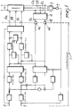
- an example of a known vector controller comprises a microprocessor, generally indicated by the reference numeral 1, which receives, from the three supply phases 2a, 2b and 2c of an asynchronous motor 3, data prepared by a converter 4, which converts the three phases into only two measurement signals 5a and 5b. Said signals are converted from analog signals into digital signals by means of analog/digital converters 6a and 6b. Information on the frequency of the asynchronous motor 3 also reaches the microprocessor 1 by means of a transducer 7. Inside the microprocessor 1, the measured data are compared with the data defined by the user, which are indicated by the reference numerals 8 and 9. The outputs 10a, 10b and 10c are transmitted by the microprocessor 1 to an inverter 11 to adjust the power supplied to the asynchronous motor 3.
- a vector controller requires a complicated hardware and software design in order to perform the necessary comparisons. From a merely constructive point of view, it furthermore requires particular precautions in order to avoid electromagnetic interference which can alter, sometimes quite significantly, the operation of said vector controller.
- the electric power P is equal to the active power absorbed by the asynchronous electric motor 14 at the terminals 15a, 15b and 15c for input to the asynchronous electric motor 14 itself, minus the usually small losses in the stator 12 of said asynchronous electric motor 14.
- the asynchronous electric motor 14 is powered by means of an inverter 16, which is in turn powered by a direct voltage or rather by a generator, indicated by the reference numeral 17, of a constant voltage E
- the electric power P is the power absorbed continuously, i.e.
- I q I d *W s .
- the final system shows that the values of the moduli of I q and I d , which are required for the vector control of an asynchronous motor, can be obtained directly from the calculation of the mechanical torque C, performed starting from the values of the supply voltage E, of the absorbed current I CC and of the operating frequency W.
- the measurement and control device according to the invention is thus reached by the supply voltage E 17 and by the absorbed current I CC 18 by means of input terminals 20a and 20b, as well as by the operating frequency W of the asynchronous electric motor 14, which is detected by means of a transducer 21 and reaches the circuit 20 by means of an input terminal 20c.
- the speed required of the asynchronous electric motor 14, translated into operating frequency W R , and the operating magnetic flux [phi] R , or rather the reactive operating current I d R are furthermore set on the input terminals 20g and 20h by the operator on selectors indicated by the same reference numerals.
- the power supply voltage V and the operating frequency W of the asynchronous electric motor 14 are transmitted from the output terminals 22a and 22b from the circuit 20 to the inverter 16.
- the measurement and control device 20 (figure 3C) comprises means for calculating a signal which represents the instantaneous mechanical torque C ist , constituted by a multiplier/divider circuit 23 which is provided with a first input terminal 20a, with a second input terminal 20b, respectively for the absorbed current I CC 18 and for the power supply voltage E 17, and with a third input terminal 20c for an electric signal which represents the instantaneous frequency W ist of the asynchronous electric motor 14.
- the frequency regulating circuit comprises a first summing node 35, in which the signal which represents the instantaneous operating frequency W ist of the asynchronous electric motor 14, coming from the fifth input terminal 20c, is subtracted from the signal which represents the operating frequency W R coming from the fourth input terminal 20g.
- the output from the first summing node 25 constitutes the input for a speed regulator 26, which calculates either a signal which represents the mechanical operating torque C R or the operating current I q R ; the relationship between these two values, which are mutually proportional, has been explained above.
- the output of said speed regulator 26 constitutes the input for a second summing node 27, in which the signal which represents the instantaneous mechanical torque C ist is subtracted from the signal which represents the mechanical operating torque C R (or the instantaneous current I q,ist is subtracted from the operating current I q R ).
- the signal which represents the instantaneous mechanical torque C ist or the instantaneous current I q,ist comes from the sixth input terminal 24.
- the output of the second summing node 27 is the input of a current regulator 28 which, starting from the signal received as input, calculates the signal which represents the required slip frequency W s R .
- the output of the current regulator 28 constitutes the input for a third summing node 29, in which the signal which represents the actual slip frequency W s , which comes from a seventh input terminal connected to a feedback branch 30 explained hereinafter, is subtracted from the signal which represents the required slip frequency W s R .
- the output of the third summing node 29 constitutes the input for a slip regulator 31, which calculates, starting from the input signal, the signal which represents the operating frequency W, which is transmitted to the inverter 16 by means of the output terminal 22a.
- the signal which represents the working frequency W is furthermore sent to the feedback branch 30.
- the feedback branch 30 comprises a fourth summing node 32, in which the signal which represents the instantaneous frequency W ist which corresponds to the speed of the asynchronous electric motor 14, coming from the eighth input terminal 20c, is subtracted from the signal which represents the operating frequency W.
- the output signal of the fourth summing node, which represents the slip frequency W s constitutes the subtrahend input of the third summing node 29.
- the voltage regulating circuit illustrated in figure 3B comprises a fifth summing node 33, in which the signal which represents the instantaneous magnetic flux [phi] ist (or the instantaneous current I ist ), coming from the tenth input terminal constituted by the terminals 24 and 30, is subtracted from the signal which represents the required operating magnetic flux [phi] R (or from the required operating current I d R ) coming from the ninth input terminal 20h.
- the instantaneous magnetic flux [phi] ist (or the instantaneous current I ist ) are calculated by means of the previously described (C/W s )1 ⁇ 2.
- the output of the fifth summing node 33 constitutes the input for a flux regulator 34, which calculates, starting from the signal received in input, the power supply voltage V to be transmitted to the inverter 16 by means of the output terminal 22b.
- said circuit processes, starting from measured values and from values preset by the operator, control signals for the inverter which supplies power to the asynchronous electric motor.
- Said scalar signals V and W regulate the power supply and the operating frequency of the asynchronous motor, and thus regulate vector values, eliminating the need for complicated matrix operations and for the use of microprocessors.
- the device according to the invention is slightly slower than the vector controllers which are conventionally used, since its reaction time is typically ten milliseconds, against the millisecond of vector controllers.
- this increase in reaction time does not negatively affect the device according to the invention, since the reaction times currently required by machines provided with asynchronous electric motors are at least one order of magnitude higher than the reaction time of the closed-loop automatic circuit according to the invention.
- the device according to the invention allows one to obtain high speeds by reducing the set operating flux [phi] R coming from the ninth input terminal 20h, so as to be able to operate at a higher frequency with a voltage equal to the maximum available value.
- the materials employed, as well as the dimensions, may be any according to the requirements.
Abstract
Description
- The present invention relates to a measurement and control device particularly for asynchronous electric motors.
- Nowadays, most of the electric motors used in the most disparate applications are constituted by caged asynchronous electric motors. For these asynchronous motors, the greatest technical problem is constituted by speed adjustment, in order to be able to compete on equal footing with direct-current motors.
- By virtue of the increasingly expanding availability of integrated circuits, microprocessors and power transistors, it is currently possible to manufacture control inverters which allow a better and more precise control of the power which supplies the asynchronous electric motor.
- The performance required of a controller for an asynchronous motor can be summarized as follows: first of all a high maximum torque, at least equal to three or four times the nominal torque of the motor, both during startup and at running speed; a rapid pickup, which means a good ratio between the maximum torque and the inertia of the motor; a fairly good precision, i.e. a high gradient of the output characteristic of torque and speed variation; an overspeed, at constant power, equal to at least three or four times the basic speed of the asynchronous motor.
- A solution to the described technical problem entails the use of open- or closed-loop inverters, for which there are problems in the uniformity of the driving of the motor if high torques or high response speeds for changes in load or in required speed are required.
- In order to solve these problems, which are particularly onerous especially in an industrial environment, complicated controllers, often termed vector controllers, have been -produced. Said controllers are usually based on circuits which detect and calculate the vectors which represent the current and the magnetic flux respectively.
- The current and magnetic flux vectors have an angular rotation rate in the air gap of the motor which is equal to the one which corresponds to the power supply frequency, and generate the mechanical torques which maintain the motion of the rotor, furthermore entailing a relative slip speed of the magnetic flux vector with respect to the rotor, which rotates at the mechanical speed of the shaft, accelerating it or overcoming its useful load.
- Such devices (figure 1) are usually based on a feedback microprocessor-based system which is complicated and expensive to manufacture, since the calculations necessary to obtain the modulus and the phase of the magnetic flux and torque vectors entail the solving of complicated matrix operations which, as is known, require a considerable expenditure of computing power of the microprocessor installed in these vector controllers, and vector controllers therefore usually require high-quality microprocessors, always having a considerable volatile memory capacity and containing application programs stored permanently in non-volatile memories; these last characteristics are not typical of ordinary microprocessors, but only of special microprocessors which usually have high costs. The design and sizing of the peripheral electronic components of the microprocessor must furthermore be particularly accurate, since the vector controller must operate in environments which are usually affected by considerable electromagnetic noise which thus usually negatively affects the electronic components placed in such environments.
- The aim of the present invention is to eliminate or substantially reduce the disadvantages described above in known types of inverters with open- or closed-loop vector controllers by providing a measurement and control device particularly for asynchronous electric motors which eliminates the use of microprocessors while maintaining the accuracy of closed-circuit control, when applied.
- Within the scope of the above aim, an object of the present invention is to provide a measurement and control device which does not require complicated matrix operations in order to obtain the information required for the correct control of the asynchronous electric motor.
- Not least object of the present invention is to provide a measurement and control device which is relatively easy to manufacture and at very competitive costs.
- This aim, these objects and others which will become apparent hereinafter are achieved by a measurement and control device particularly for asynchronous electric motors, characterized in that it comprises a multiplier/divider circuit, which has a first input terminal and a second input terminal electrically connected to a power supply of a supply inverter of said asynchronous electric motor and a third input terminal for a signal measured on said asynchronous electric motor, said multiplier/divider circuit having said output terminal, which carries an electric signal which represents a mechanical torque, electrically connected to adjustment means of said inverter, said first and second input terminals being suitable for detecting the supply voltage and the current absorbed by said inverter, said third input terminal being suitable for detecting a signal which represents the mechanical operating angular frequency of said asynchronous electric motor.
- Further characteristics and advantages of the invention will become apparent from the description of a preferred but not exclusive embodiment of a measurement and control device particularly for asynchronous electric motors according to the invention, illustrated only by way of non-limitative example in the accompanying drawings, wherein:
- figure 1 is an exemplifying diagram of a known microprocessor-based vector controller;
- figure 2 is an exemplifying diagram of an asynchronous motor powered by means of an inverter; and
- figures 3A, 3B and 3C are diagrams of embodiments of a measurement and control device particularly for asynchronous electric motors according to the invention.
- With reference to figure 1, an example of a known vector controller comprises a microprocessor, generally indicated by the
reference numeral 1, which receives, from the threesupply phases converter 4, which converts the three phases into only twomeasurement signals 5a and 5b. Said signals are converted from analog signals into digital signals by means of analog/digital converters 6a and 6b. Information on the frequency of the asynchronous motor 3 also reaches themicroprocessor 1 by means of a transducer 7. Inside themicroprocessor 1, the measured data are compared with the data defined by the user, which are indicated by thereference numerals outputs microprocessor 1 to an inverter 11 to adjust the power supplied to the asynchronous motor 3. - As is evident even from this summary description and from what has been stated, a vector controller requires a complicated hardware and software design in order to perform the necessary comparisons. From a merely constructive point of view, it furthermore requires particular precautions in order to avoid electromagnetic interference which can alter, sometimes quite significantly, the operation of said vector controller.
- The mechanical torque provided by an asynchronous motor is given, as is known, by the scalar product of the magnetic flux and electric current vectors. Control of the mechanical torque C therefore requires control of the product:

- The flux vector [phi] must have, with respect to the rotor, such a relative or slip velocity Ws that the active component Iq has the value necessary to achieve what has been described, i. e.:

- With reference to figure 2, asynchronous motor theory states that the electric power P transmitted by the
stator 12 to therotor 13 of an asynchronouselectric motor 14 corresponds to the product of the mechanical torque C and of the operating angular frequency W, i.e.:
- The electric power P, however, is equal to the active power absorbed by the asynchronous
electric motor 14 at theterminals electric motor 14 itself, minus the usually small losses in thestator 12 of said asynchronouselectric motor 14. However, if the asynchronouselectric motor 14 is powered by means of aninverter 16, which is in turn powered by a direct voltage or rather by a generator, indicated by thereference numeral 17, of a constant voltage E, the electric power P is the power absorbed continuously, i.e. the product of thesupply voltage E 17 and of the absorbed current ICC, indicated by thereference numeral 18, i.e.:

- From what has been stated above, the following expressions can be found:


- The following system is obtained from the preceding expressions:


- The final system shows that the values of the moduli of Iq and Id, which are required for the vector control of an asynchronous motor, can be obtained directly from the calculation of the mechanical torque C, performed starting from the values of the supply voltage E, of the absorbed current ICC and of the operating frequency W. If the calculated value of the slip frequency Ws is necessary, it is determined from:


power supply phases electric motor 14, which can be obtained, by way of example, by means of three current transformers, one for eachpower supply phase electric motor 14. - The operating values of the asynchronous motor have thus been obtained theoretically. A measurement and control device particularly for asynchronous electric motors according to the invention, a schematic example of which is provided in figures 3A, 3B and 3C, has been developed from these values.
- The measurement and control device according to the invention, indicated by the
reference numeral 20, is thus reached by thesupply voltage E 17 and by the absorbedcurrent I CC 18 by means ofinput terminals 20a and 20b, as well as by the operating frequency W of the asynchronouselectric motor 14, which is detected by means of atransducer 21 and reaches thecircuit 20 by means of aninput terminal 20c. The speed required of the asynchronouselectric motor 14, translated into operating frequency WR, and the operating magnetic flux [phi]R, or rather the reactive operating current Id R, are furthermore set on theinput terminals 20g and 20h by the operator on selectors indicated by the same reference numerals. The power supply voltage V and the operating frequency W of the asynchronouselectric motor 14 are transmitted from the output terminals 22a and 22b from thecircuit 20 to theinverter 16. - The measurement and control device 20 (figure 3C) comprises means for calculating a signal which represents the instantaneous mechanical torque Cist, constituted by a multiplier/
divider circuit 23 which is provided with afirst input terminal 20a, with a second input terminal 20b, respectively for the absorbedcurrent I CC 18 and for the powersupply voltage E 17, and with athird input terminal 20c for an electric signal which represents the instantaneous frequency Wist of the asynchronouselectric motor 14. The multiplier/divider circuit 23 calculates the relation:
output terminal 24. - With reference to figure 3A, the frequency regulating circuit comprises a first summing node 35, in which the signal which represents the instantaneous operating frequency Wist of the asynchronous
electric motor 14, coming from thefifth input terminal 20c, is subtracted from the signal which represents the operating frequency WR coming from the fourth input terminal 20g. - The output from the
first summing node 25 constitutes the input for aspeed regulator 26, which calculates either a signal which represents the mechanical operating torque CR or the operating current Iq R; the relationship between these two values, which are mutually proportional, has been explained above. - The output of
said speed regulator 26 constitutes the input for asecond summing node 27, in which the signal which represents the instantaneous mechanical torque Cist is subtracted from the signal which represents the mechanical operating torque CR (or the instantaneous current Iq,ist is subtracted from the operating current Iq R). The signal which represents the instantaneous mechanical torque Cist or the instantaneous current Iq,ist comes from thesixth input terminal 24. - The output of the
second summing node 27 is the input of acurrent regulator 28 which, starting from the signal received as input, calculates the signal which represents the required slip frequency Ws R. - The output of the
current regulator 28 constitutes the input for athird summing node 29, in which the signal which represents the actual slip frequency Ws, which comes from a seventh input terminal connected to afeedback branch 30 explained hereinafter, is subtracted from the signal which represents the required slip frequency Ws R. - The output of the
third summing node 29 constitutes the input for aslip regulator 31, which calculates, starting from the input signal, the signal which represents the operating frequency W, which is transmitted to theinverter 16 by means of the output terminal 22a. The signal which represents the working frequency W is furthermore sent to thefeedback branch 30. - The
feedback branch 30 comprises afourth summing node 32, in which the signal which represents the instantaneous frequency Wist which corresponds to the speed of the asynchronouselectric motor 14, coming from theeighth input terminal 20c, is subtracted from the signal which represents the operating frequency W. The output signal of the fourth summing node, which represents the slip frequency Ws, constitutes the subtrahend input of thethird summing node 29. - The voltage regulating circuit illustrated in figure 3B comprises a
fifth summing node 33, in which the signal which represents the instantaneous magnetic flux [phi]ist (or the instantaneous current Iist), coming from the tenth input terminal constituted by theterminals ninth input terminal 20h. The instantaneous magnetic flux [phi]ist (or the instantaneous current Iist) are calculated by means of the previously described (C/Ws)½. The output of thefifth summing node 33 constitutes the input for aflux regulator 34, which calculates, starting from the signal received in input, the power supply voltage V to be transmitted to theinverter 16 by means of the output terminal 22b. - Thus, as explained in the theoretical introduction to the device according to the invention, said circuit processes, starting from measured values and from values preset by the operator, control signals for the inverter which supplies power to the asynchronous electric motor. Said scalar signals V and W regulate the power supply and the operating frequency of the asynchronous motor, and thus regulate vector values, eliminating the need for complicated matrix operations and for the use of microprocessors.
- The device according to the invention is slightly slower than the vector controllers which are conventionally used, since its reaction time is typically ten milliseconds, against the millisecond of vector controllers. However, this increase in reaction time does not negatively affect the device according to the invention, since the reaction times currently required by machines provided with asynchronous electric motors are at least one order of magnitude higher than the reaction time of the closed-loop automatic circuit according to the invention.
- In particular, the device according to the invention allows one to obtain high speeds by reducing the set operating flux [phi]R coming from the
ninth input terminal 20h, so as to be able to operate at a higher frequency with a voltage equal to the maximum available value. - The invention thus conceived is susceptible to numerous modifications and variations, all of which are within the scope of the inventive concept. For example, the electronic components required to provide the various regulators can vary according to the intended implementations. All the details may furthermore be replaced with other technically equivalent elements.
- In practice, the materials employed, as well as the dimensions, may be any according to the requirements.
- Where technical features mentioned in any claim are followed by reference signs, those reference signs have been included for the sole purpose of increasing the intelligibility of the claims and accordingly such reference signs do not have any limiting effect on the scope of each element identified by way of example by such reference signs.
Claims (4)
- Measurement and control device particularly for asynchronous electric motors, characterized in that it comprises a multiplier/divider circuit which has a first input terminal and a second input terminal, which are electrically connected to a power supply of an inverter for supplying power to said asynchronous electric motor, and a third input terminal for a signal measured on said asynchronous electric motor, said multiplier/divider circuit having said output terminal, which carries an electric signal which represents a mechanical torque, electrically connected to regulating means of said inverter, said first and second input terminals being suitable for detecting the power supply voltage and the current absorbed by said inverter, said third input terminal being suitable for detecting a signal which represents the mechanical operating frequency of said asynchronous electric motor.
- Device according to claim 1, characterized in that said regulating means comprise a voltage regulating circuit and a frequency regulating circuit, said circuits comprising a plurality of input terminals for signals which are selectively measured on an asynchronous electric motor, on an inverter for supplying power to said asynchronous electric motor, from selectors which can be actuated by an operator and from said multiplier/divider circuit.
- Device according to claim 2, characterized in that said frequency regulating circuit comprises a first summing node, said first summing node comprising a fourth input terminal which is electrically connected to a selector which can be actuated by an operator and a fifth input terminal for a signal measured on said asynchronous electric motor, said first summing node having an output terminal which is electrically connected to an input terminal of a speed regulator, said speed regulator having an output terminal which is electrically connected to a second summing node, said second summing node having a sixth input terminal which is electrically connected to an output terminal of said multiplier/divider circuit, said second summing node comprising an output terminal which is electrically connected to an input terminal of a current regulator, said current regulator having an output terminal which is electrically connected to a third summing node, said third summing node having a seventh input terminal which is electrically connected to an output terminal of a fourth summing node and an output terminal which is electrically connected to an input terminal of a slip regulator, said slip regulator comprising an output terminal which can be electrically connected to said inverter and can be electrically connected to a fourth summing node, said fourth summing node comprising an eighth input terminal for a signal measured on said asynchronous electric motor.
- Device according to claim 2, characterized in that said voltage regulating circuit comprises a fifth summing node which has a ninth input terminal for a signal coming from a selector which can be actuated by an operator and a tenth input terminal for a signal which comes from said multiplier/divider circuit and is related to the signal coming from said fourth summing node, said fifth summing node comprising an output terminal which can be electrically connected to an input terminal of a flow regulator, said flow regulator having an output terminal which can be electrically connected to said inverter.
Applications Claiming Priority (2)
| Application Number | Priority Date | Filing Date | Title |
|---|---|---|---|
| IT02110990A IT1243458B (en) | 1990-07-27 | 1990-07-27 | MEASUREMENT AND CONTROL DEVICE PARTICULARLY FOR ASYNCHRONOUS ELECTRIC MOTORS |
| IT2110990 | 1990-07-27 |
Publications (3)
| Publication Number | Publication Date |
|---|---|
| EP0468499A2 true EP0468499A2 (en) | 1992-01-29 |
| EP0468499A3 EP0468499A3 (en) | 1993-06-30 |
| EP0468499B1 EP0468499B1 (en) | 1996-03-13 |
Family
ID=11176881
Family Applications (1)
| Application Number | Title | Priority Date | Filing Date |
|---|---|---|---|
| EP91112506A Expired - Lifetime EP0468499B1 (en) | 1990-07-27 | 1991-07-25 | Measurement and control device particularly for asynchronous electric motors. |
Country Status (5)
| Country | Link |
|---|---|
| EP (1) | EP0468499B1 (en) |
| AT (1) | ATE135508T1 (en) |
| DE (1) | DE69117826T2 (en) |
| ES (1) | ES2087188T3 (en) |
| IT (1) | IT1243458B (en) |
Cited By (3)
| Publication number | Priority date | Publication date | Assignee | Title |
|---|---|---|---|---|
| EP0548676A1 (en) * | 1991-12-11 | 1993-06-30 | STUDIO TECNICO ING. MONTESSORI S.a.s., di GIUSEPPE MONTESSORI & Co. | Flux regulator particularly for drivers of asynchronous electric motors |
| WO1996001522A1 (en) * | 1994-07-04 | 1996-01-18 | Luossavaara Kiirunavaara Ab | Method for determining torque requirements |
| WO2001027637A1 (en) * | 1999-10-12 | 2001-04-19 | Abb Ab | A device and a method for estimating the speed of a slip ring asynchronous machine |
Citations (6)
| Publication number | Priority date | Publication date | Assignee | Title |
|---|---|---|---|---|
| US4484126A (en) * | 1982-09-07 | 1984-11-20 | Imec Corporation | Induction motor controller |
| JPS59220090A (en) * | 1983-05-26 | 1984-12-11 | Akira Yamamura | Control system induction motor |
| JPS60176487A (en) * | 1984-02-21 | 1985-09-10 | Mitsubishi Electric Corp | Speed controller of induction motor |
| JPS618640A (en) * | 1984-06-22 | 1986-01-16 | Mitsubishi Electric Corp | Torque detecting device of alternating current electric motor |
| JPS62173950A (en) * | 1986-01-28 | 1987-07-30 | Toshiba Corp | Instantaneous torque-measuring device for induction motor |
| JPH1030486A (en) * | 1996-07-17 | 1998-02-03 | Mitsubishi Motors Corp | Accumulator fuel injection controlling device |
-
1990
- 1990-07-27 IT IT02110990A patent/IT1243458B/en active IP Right Grant
-
1991
- 1991-07-25 DE DE69117826T patent/DE69117826T2/en not_active Expired - Fee Related
- 1991-07-25 AT AT91112506T patent/ATE135508T1/en not_active IP Right Cessation
- 1991-07-25 ES ES91112506T patent/ES2087188T3/en not_active Expired - Lifetime
- 1991-07-25 EP EP91112506A patent/EP0468499B1/en not_active Expired - Lifetime
Patent Citations (6)
| Publication number | Priority date | Publication date | Assignee | Title |
|---|---|---|---|---|
| US4484126A (en) * | 1982-09-07 | 1984-11-20 | Imec Corporation | Induction motor controller |
| JPS59220090A (en) * | 1983-05-26 | 1984-12-11 | Akira Yamamura | Control system induction motor |
| JPS60176487A (en) * | 1984-02-21 | 1985-09-10 | Mitsubishi Electric Corp | Speed controller of induction motor |
| JPS618640A (en) * | 1984-06-22 | 1986-01-16 | Mitsubishi Electric Corp | Torque detecting device of alternating current electric motor |
| JPS62173950A (en) * | 1986-01-28 | 1987-07-30 | Toshiba Corp | Instantaneous torque-measuring device for induction motor |
| JPH1030486A (en) * | 1996-07-17 | 1998-02-03 | Mitsubishi Motors Corp | Accumulator fuel injection controlling device |
Non-Patent Citations (9)
| Title |
|---|
| CONFERENCE RECORD OF THE 1988 IEEE INDUSTRY APPLICATIONS SOCIETY ANNUAL MEETING 2 October 1987, PITTSBURGH, PENNSYLVANIA pages 489 - 492 H.SHIERLING 'Fast and reliable commissioning of ac variable speed drives by self-commissioning' * |
| IEEE TRANSACTIONS ON INDUSTRIAL ELECTRONICS vol. 37, no. 6, December 1990, N.Y. USA pages 477 - 482 C.C.CHAN & AL. 'An effective Method for Rotor Resistance Identification for high-performance induction motor vector control' * |
| PATENT ABSTRACTS OF JAPAN vol. 010, no. 154 (P-463)4 June 1986 & JP-A-61 008 640 ( MITSUBISHI DENKI K.K. ) 16 January 1986 * |
| PATENT ABSTRACTS OF JAPAN vol. 012, no. 017 (E-574)19 January 1988 & JP-A-62 173 950 ( TOSHIBA CORP ) 30 July 1987 * |
| PATENT ABSTRACTS OF JAPAN vol. 013, no. 218 (E-761)22 May 1989 & JP-A-10 30 486 ( TODOROKI SANGYO K.K. ) 1 February 1989 * |
| PATENT ABSTRACTS OF JAPAN vol. 014, no. 216 (E-924)8 May 1990 & JP-A-20 51 386 ( TOSHIBA CORP. ) 21 February 1990 * |
| PATENT ABSTRACTS OF JAPAN vol. 10, no. 16 (E-375)(2073) 22 January 1986 & JP-A-60 176 487 ( MITSUBISHI DENKI K.K. ) 10 September 1985 * |
| PATENT ABSTRACTS OF JAPAN vol. 9, no. 89 (E-309)(1812) 18 April 1985 & JP-A-59 220 090 ( AKIRA YAMAMURA ) 11 December 1984 * |
| PESC 88 IEEE POWER ELECTRONICS SPECIALISTS CONFERENCE vol. 2, 11 April 1988, KYOTO, JP pages 885 - 892 N.TSUJI & AL. 'stability analysis of a csi-fed induction motor with digital vector controller' * |
Cited By (4)
| Publication number | Priority date | Publication date | Assignee | Title |
|---|---|---|---|---|
| EP0548676A1 (en) * | 1991-12-11 | 1993-06-30 | STUDIO TECNICO ING. MONTESSORI S.a.s., di GIUSEPPE MONTESSORI & Co. | Flux regulator particularly for drivers of asynchronous electric motors |
| WO1996001522A1 (en) * | 1994-07-04 | 1996-01-18 | Luossavaara Kiirunavaara Ab | Method for determining torque requirements |
| WO2001027637A1 (en) * | 1999-10-12 | 2001-04-19 | Abb Ab | A device and a method for estimating the speed of a slip ring asynchronous machine |
| US6995539B1 (en) | 1999-10-12 | 2006-02-07 | Abb Ab | Device and a method for estimating the speed of a slip ring asynchronous machine |
Also Published As
| Publication number | Publication date |
|---|---|
| IT1243458B (en) | 1994-06-15 |
| IT9021109A0 (en) | 1990-07-27 |
| IT9021109A1 (en) | 1992-01-27 |
| DE69117826T2 (en) | 1996-11-21 |
| ES2087188T3 (en) | 1996-07-16 |
| EP0468499B1 (en) | 1996-03-13 |
| ATE135508T1 (en) | 1996-03-15 |
| EP0468499A3 (en) | 1993-06-30 |
| DE69117826D1 (en) | 1996-04-18 |
Similar Documents
| Publication | Publication Date | Title |
|---|---|---|
| US5874821A (en) | Method and apparatus for controlling a brushless electro motor by determining the absolute phase position of the rotor relative to the stator | |
| JP2833463B2 (en) | AC motor rotation torque detector | |
| US3919609A (en) | Method and circuit for reducing the torque ripple of a rotating-field machine | |
| US3805135A (en) | Apparatus for field-oriented control or regulation of asynchronous machines | |
| US4888538A (en) | System for remote transmission of angular position and force between master and slave shafts | |
| US4593240A (en) | Method and apparatus for determining the flux vector of a rotating-field machine from the stator current and the stator voltage, and the application thereof | |
| CA1299642C (en) | Universal field-oriented controller | |
| US4701839A (en) | Sampled data servo control system with field orientation | |
| US4282473A (en) | Rotating field machine drive and method | |
| US4814683A (en) | Induction motor control apparatus | |
| US4611155A (en) | Servo control circuit | |
| US6013999A (en) | Stepper motor control that adjusts to motor loading | |
| GB1379437A (en) | Control or regulation of an asynchronous electrical machine | |
| EP0241045B1 (en) | Motion control apparatus for induction motor | |
| CA1226331A (en) | Method and apparatus for determining the flux vector of a rotating-field machine | |
| JPH0153000B2 (en) | ||
| EP0104909A2 (en) | Servomotor control method and apparatus therefor | |
| US4956593A (en) | Servo motor controlling method | |
| US5719482A (en) | Process and device for field-oriented control of a polyphase machine | |
| EP0468499B1 (en) | Measurement and control device particularly for asynchronous electric motors. | |
| US4818927A (en) | Acceleration/deceleration control apparatus using slip speed | |
| US4322672A (en) | Electric motor control apparatus | |
| JPH0410319B2 (en) | ||
| US5936372A (en) | Control device for a reluctance type synchronous motor | |
| US4475074A (en) | Apparatus for determining the common frequency of two independently variable electrical a-c variables, especially in a rotating-field machine |
Legal Events
| Date | Code | Title | Description |
|---|---|---|---|
| PUAI | Public reference made under article 153(3) epc to a published international application that has entered the european phase |
Free format text: ORIGINAL CODE: 0009012 |
|
| AK | Designated contracting states |
Kind code of ref document: A2 Designated state(s): AT BE CH DE DK ES FR GB GR IT LI LU NL SE |
|
| PUAL | Search report despatched |
Free format text: ORIGINAL CODE: 0009013 |
|
| AK | Designated contracting states |
Kind code of ref document: A3 Designated state(s): AT BE CH DE DK ES FR GB GR IT LI LU NL SE |
|
| 17P | Request for examination filed |
Effective date: 19931221 |
|
| 17Q | First examination report despatched |
Effective date: 19940304 |
|
| GRAH | Despatch of communication of intention to grant a patent |
Free format text: ORIGINAL CODE: EPIDOS IGRA |
|
| GRAA | (expected) grant |
Free format text: ORIGINAL CODE: 0009210 |
|
| AK | Designated contracting states |
Kind code of ref document: B1 Designated state(s): AT BE CH DE DK ES FR GB GR IT LI LU NL SE |
|
| PG25 | Lapsed in a contracting state [announced via postgrant information from national office to epo] |
Ref country code: IT Free format text: LAPSE BECAUSE OF FAILURE TO SUBMIT A TRANSLATION OF THE DESCRIPTION OR TO PAY THE FEE WITHIN THE PRE;WARNING: LAPSES OF ITALIAN PATENTS WITH EFFECTIVE DATE BEFORE 2007 MAY HAVE OCCURRED AT ANY TIME BEFORE 2007. THE CORRECT EFFECTIVE DATE MAY BE DIFFERENT FROM THE ONE RECORDED.SCRIBED TIME-LIMIT Effective date: 19960313 Ref country code: GR Free format text: LAPSE BECAUSE OF FAILURE TO SUBMIT A TRANSLATION OF THE DESCRIPTION OR TO PAY THE FEE WITHIN THE PRESCRIBED TIME-LIMIT Effective date: 19960313 Ref country code: BE Effective date: 19960313 Ref country code: DK Effective date: 19960313 Ref country code: AT Effective date: 19960313 Ref country code: NL Free format text: LAPSE BECAUSE OF FAILURE TO SUBMIT A TRANSLATION OF THE DESCRIPTION OR TO PAY THE FEE WITHIN THE PRESCRIBED TIME-LIMIT Effective date: 19960313 |
|
| REF | Corresponds to: |
Ref document number: 135508 Country of ref document: AT Date of ref document: 19960315 Kind code of ref document: T |
|
| REF | Corresponds to: |
Ref document number: 69117826 Country of ref document: DE Date of ref document: 19960418 |
|
| PG25 | Lapsed in a contracting state [announced via postgrant information from national office to epo] |
Ref country code: SE Effective date: 19960613 |
|
| REG | Reference to a national code |
Ref country code: ES Ref legal event code: BA2A Ref document number: 2087188 Country of ref document: ES Kind code of ref document: T3 |
|
| ET | Fr: translation filed | ||
| REG | Reference to a national code |
Ref country code: ES Ref legal event code: FG2A Ref document number: 2087188 Country of ref document: ES Kind code of ref document: T3 |
|
| PG25 | Lapsed in a contracting state [announced via postgrant information from national office to epo] |
Ref country code: LU Free format text: LAPSE BECAUSE OF NON-PAYMENT OF DUE FEES Effective date: 19960731 |
|
| RAP2 | Party data changed (patent owner data changed or rights of a patent transferred) |
Owner name: EMZOMA S.N.C. DI ZONI U. & C. |
|
| NLV1 | Nl: lapsed or annulled due to failure to fulfill the requirements of art. 29p and 29m of the patents act | ||
| PLBE | No opposition filed within time limit |
Free format text: ORIGINAL CODE: 0009261 |
|
| STAA | Information on the status of an ep patent application or granted ep patent |
Free format text: STATUS: NO OPPOSITION FILED WITHIN TIME LIMIT |
|
| 26N | No opposition filed | ||
| GBPC | Gb: european patent ceased through non-payment of renewal fee |
Effective date: 19970725 |
|
| REG | Reference to a national code |
Ref country code: GB Ref legal event code: 728V |
|
| REG | Reference to a national code |
Ref country code: GB Ref legal event code: 732E |
|
| REG | Reference to a national code |
Ref country code: GB Ref legal event code: 728Y |
|
| REG | Reference to a national code |
Ref country code: GB Ref legal event code: IF02 |
|
| PGFP | Annual fee paid to national office [announced via postgrant information from national office to epo] |
Ref country code: ES Payment date: 20050719 Year of fee payment: 15 Ref country code: GB Payment date: 20050719 Year of fee payment: 15 |
|
| PGFP | Annual fee paid to national office [announced via postgrant information from national office to epo] |
Ref country code: FR Payment date: 20050722 Year of fee payment: 15 |
|
| PGFP | Annual fee paid to national office [announced via postgrant information from national office to epo] |
Ref country code: CH Payment date: 20050906 Year of fee payment: 15 |
|
| PGFP | Annual fee paid to national office [announced via postgrant information from national office to epo] |
Ref country code: DE Payment date: 20050922 Year of fee payment: 15 |
|
| REG | Reference to a national code |
Ref country code: CH Ref legal event code: NV Representative=s name: ROTTMANN, ZIMMERMANN + PARTNER AG Ref country code: CH Ref legal event code: PUE Owner name: EMZOMA S.N.C. DI ZONI U.AND C; VIA G.P. CLERICI 123, GERENZANO (IT) Ref country code: CH Ref legal event code: EP |
|
| PG25 | Lapsed in a contracting state [announced via postgrant information from national office to epo] |
Ref country code: GB Free format text: LAPSE BECAUSE OF NON-PAYMENT OF DUE FEES Effective date: 20060725 |
|
| PG25 | Lapsed in a contracting state [announced via postgrant information from national office to epo] |
Ref country code: LI Free format text: LAPSE BECAUSE OF NON-PAYMENT OF DUE FEES Effective date: 20060731 Ref country code: CH Free format text: LAPSE BECAUSE OF NON-PAYMENT OF DUE FEES Effective date: 20060731 |
|
| PG25 | Lapsed in a contracting state [announced via postgrant information from national office to epo] |
Ref country code: DE Free format text: LAPSE BECAUSE OF NON-PAYMENT OF DUE FEES Effective date: 20070201 |
|
| REG | Reference to a national code |
Ref country code: CH Ref legal event code: PL |
|
| GBPC | Gb: european patent ceased through non-payment of renewal fee |
Effective date: 20060725 |
|
| REG | Reference to a national code |
Ref country code: FR Ref legal event code: ST Effective date: 20070330 |
|
| REG | Reference to a national code |
Ref country code: ES Ref legal event code: FD2A Effective date: 20060726 |
|
| PG25 | Lapsed in a contracting state [announced via postgrant information from national office to epo] |
Ref country code: ES Free format text: LAPSE BECAUSE OF NON-PAYMENT OF DUE FEES Effective date: 20060726 |
|
| PG25 | Lapsed in a contracting state [announced via postgrant information from national office to epo] |
Ref country code: FR Free format text: LAPSE BECAUSE OF NON-PAYMENT OF DUE FEES Effective date: 20060731 |