EP0468145A1 - Apparatus for the reading/writing of credit cards - Google Patents
Apparatus for the reading/writing of credit cards Download PDFInfo
- Publication number
- EP0468145A1 EP0468145A1 EP91106767A EP91106767A EP0468145A1 EP 0468145 A1 EP0468145 A1 EP 0468145A1 EP 91106767 A EP91106767 A EP 91106767A EP 91106767 A EP91106767 A EP 91106767A EP 0468145 A1 EP0468145 A1 EP 0468145A1
- Authority
- EP
- European Patent Office
- Prior art keywords
- carriage
- end position
- card
- card holder
- flap
- Prior art date
- Legal status (The legal status is an assumption and is not a legal conclusion. Google has not performed a legal analysis and makes no representation as to the accuracy of the status listed.)
- Granted
Links
Images
Classifications
-
- G—PHYSICS
- G06—COMPUTING; CALCULATING OR COUNTING
- G06K—GRAPHICAL DATA READING; PRESENTATION OF DATA; RECORD CARRIERS; HANDLING RECORD CARRIERS
- G06K13/00—Conveying record carriers from one station to another, e.g. from stack to punching mechanism
- G06K13/02—Conveying record carriers from one station to another, e.g. from stack to punching mechanism the record carrier having longitudinal dimension comparable with transverse dimension, e.g. punched card
- G06K13/08—Feeding or discharging cards
- G06K13/0868—Feeding or discharging cards using an arrangement for keeping the feeding or insertion slot of the card station clean of dirt, or to avoid feeding of foreign or unwanted objects into the slot
- G06K13/0875—Feeding or discharging cards using an arrangement for keeping the feeding or insertion slot of the card station clean of dirt, or to avoid feeding of foreign or unwanted objects into the slot the arrangement comprising a shutter for blocking at least part of the card insertion slot
-
- G—PHYSICS
- G06—COMPUTING; CALCULATING OR COUNTING
- G06K—GRAPHICAL DATA READING; PRESENTATION OF DATA; RECORD CARRIERS; HANDLING RECORD CARRIERS
- G06K13/00—Conveying record carriers from one station to another, e.g. from stack to punching mechanism
- G06K13/02—Conveying record carriers from one station to another, e.g. from stack to punching mechanism the record carrier having longitudinal dimension comparable with transverse dimension, e.g. punched card
- G06K13/08—Feeding or discharging cards
- G06K13/0806—Feeding or discharging cards using an arrangement for ejection of an inserted card
- G06K13/0831—Feeding or discharging cards using an arrangement for ejection of an inserted card the ejection arrangement comprising a slide, carriage or drawer
-
- G—PHYSICS
- G06—COMPUTING; CALCULATING OR COUNTING
- G06K—GRAPHICAL DATA READING; PRESENTATION OF DATA; RECORD CARRIERS; HANDLING RECORD CARRIERS
- G06K13/00—Conveying record carriers from one station to another, e.g. from stack to punching mechanism
- G06K13/02—Conveying record carriers from one station to another, e.g. from stack to punching mechanism the record carrier having longitudinal dimension comparable with transverse dimension, e.g. punched card
- G06K13/08—Feeding or discharging cards
- G06K13/085—Feeding or discharging cards using an arrangement for locking the inserted card
-
- G—PHYSICS
- G06—COMPUTING; CALCULATING OR COUNTING
- G06K—GRAPHICAL DATA READING; PRESENTATION OF DATA; RECORD CARRIERS; HANDLING RECORD CARRIERS
- G06K7/00—Methods or arrangements for sensing record carriers, e.g. for reading patterns
- G06K7/0013—Methods or arrangements for sensing record carriers, e.g. for reading patterns by galvanic contacts, e.g. card connectors for ISO-7816 compliant smart cards or memory cards, e.g. SD card readers
- G06K7/0021—Methods or arrangements for sensing record carriers, e.g. for reading patterns by galvanic contacts, e.g. card connectors for ISO-7816 compliant smart cards or memory cards, e.g. SD card readers for reading/sensing record carriers having surface contacts
-
- G—PHYSICS
- G06—COMPUTING; CALCULATING OR COUNTING
- G06K—GRAPHICAL DATA READING; PRESENTATION OF DATA; RECORD CARRIERS; HANDLING RECORD CARRIERS
- G06K7/00—Methods or arrangements for sensing record carriers, e.g. for reading patterns
- G06K7/0013—Methods or arrangements for sensing record carriers, e.g. for reading patterns by galvanic contacts, e.g. card connectors for ISO-7816 compliant smart cards or memory cards, e.g. SD card readers
- G06K7/0086—Methods or arrangements for sensing record carriers, e.g. for reading patterns by galvanic contacts, e.g. card connectors for ISO-7816 compliant smart cards or memory cards, e.g. SD card readers the connector comprising a circuit for steering the operations of the card connector
- G06K7/0091—Methods or arrangements for sensing record carriers, e.g. for reading patterns by galvanic contacts, e.g. card connectors for ISO-7816 compliant smart cards or memory cards, e.g. SD card readers the connector comprising a circuit for steering the operations of the card connector the circuit comprising an arrangement for avoiding intrusions and unwanted access to data inside of the connector
Definitions
- the invention relates to a device for reading and writing value cards of the type mentioned in the preamble of claim 1.
- a device of this type is known (DE-OS 3 916 812), in which a card holder is slidably arranged in a housing. In a first end position, a value card can be inserted into the card holder through an insertion slot arranged in the housing. The card holder is moved to a second end position by manually operating a rotary slide. Even before the second end position has been reached completely, the insertion slot is closed on the one hand by the rotary slide and on the other hand a contact carrier is moved in such a way that the contact elements arranged thereon are connected to the contact tracks of the prepaid card.
- DE-OS 3 916 783 Another device is known (DE-OS 3 916 783), in which a drawer is arranged in a housing and can be moved manually from a first end position into a second end position. In the first end position, a value card can be inserted in the drawer. In the second end position, the prepaid card is connected to a reading and writing device inaccessible to the user. Even before the drawer has fully reached the second end position, a contact carrier is moved through the drawer in such a way that the contact elements arranged thereon are connected to the contact tracks on the prepaid card.
- the invention has for its object to provide a card reader for prepaid cards, in which fraudulent manipulation and destruction by vandalism are largely impossible and which should be simple and inexpensive.
- the invention consists in the features specified in the characterizing part of claim 1. Advantageous refinements result from the subclaims.
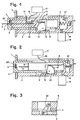
- 1 means a front panel of a device for reading and writing value cards.
- a housing 2 which serves as a guide for a carriage 3, which is longitudinally displaceable between a first end position (FIG. 1) and a second end position (FIG. 2).
- the front part of the carriage 3 protrudes from the front plate 1 both in the first and in the second end position.
- An insertion slot 4 for prepaid cards 5 is arranged on the front side of the front part of the carriage 3.
- a card receptacle 6, Arranged behind the insertion slot 4 is a card receptacle 6, which is also longitudinally displaceable in the carriage 3, for receiving a value card 5 which contains, for example, an electronic circuit.
- the value card 5 is guided on all sides in the card holder 6, a stop limiting the insertion depth of the value card 5.
- a gear segment 10 composed of two toothings 11, 12 is rotatably mounted in the carriage 3. One toothing 11 meshes with a first toothed rack 8 arranged on the card holder 6 and the other toothing 12 engages with a second toothed rack 9 arranged on the housing 2.
- a compression spring 13 is arranged between the carriage 3 and the housing 2 such that the carriage 3 to the front, i. H. in the direction of the front panel 1. The path of the carriage 3 is limited by the gear segment 10, which strikes both in the first and in the second end position.
- a contacting device 14 with contact springs 15 is arranged in the card holder 6.
- the contact springs 15 are connected to a control unit 17 with a flexible cable 16, for example with a multi-core ribbon cable.
- the control unit 17 contains all the circuits which are necessary for monitoring the device and for reading and writing to value cards 5.
- a flap 20 arranged behind the insertion slot 4 releases the insertion slot 4 in the first end position and closes it in the second end position.
- a switch 21 controlled by the carriage 3 is open in the first end position and closed in the second end position. The switch 21 is connected to the control unit 17 by cables, not shown.
- the device In the first end position, the device is ready to accept a value card 5.
- the carriage 3 and the card holder 6 are moved all the way to the front, ie towards the front plate 1.
- the flap 20 is open, ie it releases the insertion slot 4.
- a value card 5 can be inserted through the insertion slot 4 into the card holder 6. Still before the value card 5 is fully inserted, it comes into contact with the contact springs 15.
- the card holder 6 is moved in the direction of insertion of the value card 5. Via the rack 8 and the toothing 11, the linear movement of the card holder 6 translates into a rotary movement of the gear segment 10.
- the toothing 12 rolls on the rack 9.
- the carriage 3 Since the gear segment 10 is mounted in the carriage 3, the carriage 3 also moves in the insertion direction of the prepaid card 5 and in the process tensions the compression spring 13. Since the pitch circle of the toothing 11 is, for example, twice as large as that of the toothing 12, the card holder 6 is placed , based on the housing 2, three times the way back as the carriage 3. This has the consequence that the prepaid card 5 is drawn into the carriage 3. By manual pressure on the carriage 3, both this and the card holder 6 are moved into the end position (FIG. 2). The flap 20 is closed in the end position and thus prevents any access to the value card 5.
- the switch 21 closes.
- the control device 17 then excites the electromagnet 19, which lifts the plunger 18 to such an extent that it holds the carriage 3 in the second end position, and at the same time releases a reading and writing process.
- the electromagnet 19 is switched off by the control unit 17. So that the car 3 is released.
- the compression spring 13 moves the carriage 3 and thus also the card holder 6 back into the first end position.
- the flap 20 opens and the value card 5 is pushed out of the insertion slot 4. In the first end position, the value card 5 can be removed from the device.
- the card holder 6 is thus arranged displaceably in a displaceable carriage 3 and means are arranged which convert a relative movement between the housing 2 and the carriage 3 into a relative movement between the card holder 6 and the carriage 3 such that when manual Pressure on the carriage 3, a value card 5 inserted into the card holder 6 is drawn into the carriage 3.
- Such a device offers the advantage that the value card 5 is drawn into the interior of the device without the need for motor means. It is therefore withdrawn from the user during the reading and writing process. Accidental or even intentional removal of the value card 5 during the reading and writing process is not possible.
- the insertion slot can be closed by the flap 20. Both the prepaid card 5 and the contacting device 14 are thus inaccessible to the user during the reading and writing process. Tampering with the prepaid card 5 or the contacting device 14 is made impossible in this way.
- the housing 2, the carriage 3 and the card receptacle 6 are designed to be open at the bottom, then foreign bodies which do not correspond to the format of the value card 5 are output at the bottom. This makes it difficult to clog the device.
- an energy store is arranged, which is loaded when the card holder 6 is manually inserted from the first end position into the second end position and which automatically releases the card holder 6 from the second end position into the first end position after the plunger 18 is released by the plunger 18 moved back without the need for an auxiliary drive.
- the device is also built robustly, consists of a few components, does not require a drive motor and is therefore inexpensive. It can be used universally, i. H. Instead of the contacting device 14, a corresponding reading and writing device for optically or magnetically coded value cards can also be used.
- the path that the carriage 3 and the card holder 6 travel from the first end position to the second end position can be chosen as desired by selecting the pitch circle diameter of the toothings 11, 12. With the same pitch circle diameter, the card holder 6 moves twice as far as the carriage 3, based on the housing 2.
- the gear segment 10 can be arranged both perpendicularly and horizontally to the map plane. In the second case in particular, a space-saving arrangement is possible.
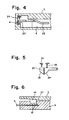
- FIG. 3 shows a lever 22 which is rotatably mounted in the carriage 3.
- the two arms of the lever 22 of different lengths each have a slot.
- a first driver pin arranged in the card holder 6 engages in the slot of the longer arm and a second driver pin arranged in the housing 2 engages in the slot of the shorter arm of the lever 22.
- the driver pins are so engaged with the lever 22 that any movement of the card holder 6 on the carriage 3 and vice versa returns is transmitted.
- the displacement can be chosen arbitrarily.
- lever 22 it is also possible to store the lever 22 in the housing 2 or in the card holder 6 instead of in the carriage 3.
- a fixed bearing point can also be dispensed with and the lever 22 can be formed with three slots, in which a driver pin arranged in the housing 1, in the carriage 3 and in the card holder 6 engages. The function of the arrangement remains the same in all cases.
- the flap 20 is designed as a U-shaped bracket, the two arms each carrying a pin in the middle, which are rotatably mounted in the carriage 3.
- the ends of the two arms are designed as drivers which engage in two grooves 23 arranged in the side walls of the card holder 6.
- the grooves 23 are composed of three parts. Two parts run in the direction of movement of the card holder 6 and a connecting part is arranged inclined thereto.
- a switch 24 is arranged such that it is closed when the flap 20 closes the insertion slot 4. It is connected to the control unit 17 with cables (not shown) and linked to the switch 21 in an AND function.
- the flap 20 is positively guided by the grooves 23. In the first end position of the card holder 6, the flap 20 opens the insertion slot 4, in the second end position the flap 20 closes the insertion slot 4.
- the flap 20 is designed as a U-shaped bracket, the two arms of which are rotatably supported by the ends in the carriage 3.
- the flap 20 is formed with a front and a rear run-on slope 25 ', 25 "for the front and the rear edge of the prepaid card 5.
- a spring 26 presses the flap 20 down so that the insertion slot 4 is closed.
- the switch 24 monitors the position of the flap 20.
- the front edge of the value card 5 presses on the front run-on bevel 25 'of the flap 20.
- the angle of the run-up bevel 25' is selected such that the flap 20 is opened by printing the value card 5.
- the flap 20 closes. If the value card 5 has been extended by wires or the like, the flap 20 cannot completely close.
- the switch 24 for monitoring the flap 20 thus remains open and the control device 17 blocks the writing and reading process.
- the rear edge of the value card 5 presses on the rear run-on bevel 25 "of the flap 20, which is thereby opened. After the value card 5 is removed from the device, the flap 20 closes again.
- the two chamfers 25 ', 25 are thus designed such that the pressure of the front edge or the rear edge of the prepaid card 5 on the respective chamfer 25', 25" opens the flap 20.
- the insertion slot 4 is advantageously also closed in the first end position. The penetration of dust into the device and the associated disturbances are thus avoided.
- the contacting device 14 is inserted in a recess in the card holder 6 in such a way that it is carried along by the card holder 6 in the direction of movement, but is displaceable in the direction perpendicular to the direction of movement.
- the contacting device 14 is pressed by a spring (not shown) against an inclined surface 27 arranged in the carriage 3, which is designed such that the contacting device 14 is lifted from the value card 5 in the first end position and is connected to the value card 5 in the second end position .
- the contacting device 14 slides along the inclined surface 27. It is moved against the value card 5 against the spring force. Shortly before the second end position is reached, the contact springs 15 rest on the contact surfaces of the value card 5.
- both the contact springs 15 and the contact surfaces on the value card 5 are protected. This extends the life of both the device and the prepaid card 5. The fact that the contact springs 15 do not slide over the value card 5 also prevents the value card 5 from being scratched.
- the Kon Clock springs 15 can be designed as inclined leaf springs, which are bent after the first contact with the value card 5 and thereby make a relative movement to the value card 5. Dirt parts on the contact surface of the value card 5 are thereby pushed aside and any oxide layers on the contact surface are broken up. Secure contacting is possible.
- the clamping device 7 for the value cards 5 is also integrated into the contacting device 14, in such a way that the value card 5 is only clamped during the displacement from the first to the second end position.
- a value card 5 can then be inserted or removed into the device without having to overcome a clamping force of the clamping device 7.
- the described device for reading and writing value cards offers several advantages. It is easy to use by the user. The insertion of the prepaid card 5 into the card holder 6 and the displacement thereof from the first end position to the second end position takes place in the same sequence of movements, that is to say automatically. The value cards 5 are inaccessible to the user during the reading and writing process. Attempts to defraud are thus made more difficult.
- the contacting device 14 is designed such that both the contact springs 15 and the value card 5 are protected.
- a read and write process is only released when various conditions are met. After the reading and writing process has ended, the value card 5 is automatically output from the insertion slot 4, without the need for a motorized drive. Despite these advantageous designs, the device is simple and robust. It is therefore inexpensive to manufacture and operate.
Abstract
Description
Die Erfindung bezieht sich auf eine Vorrichtung zum Lesen und Beschreiben von Wertkarten der im Oberbegriff des Anspruchs 1 genannten Art.The invention relates to a device for reading and writing value cards of the type mentioned in the preamble of claim 1.
Es ist eine Vorrichtung dieser Art bekannt (DE-OS 3 916 812), bei der eine Kartenaufnahme in einem Gehäuse verschiebbar angeordnet ist. In einer ersten Endstellung kann eine Wertkarte durch einen im Gehäuse angeordneten Einführschlitz in die Kartenaufnahme eingeschoben werden. Durch das manuelle Betätigen eines Drehschiebers wird die Kartenaufnahme in eine zweite Endstellung bewegt. Noch bevor die zweite Endstellung ganz erreicht ist, wird durch den Drehschieber einerseits der Einführschlitz verschlossen und andererseits wird ein Kontaktträger derart bewegt, dass die darauf angeordneten Kontaktelemente mit den Kontaktbahnen der Wertkarte verbunden werden.A device of this type is known (DE-OS 3 916 812), in which a card holder is slidably arranged in a housing. In a first end position, a value card can be inserted into the card holder through an insertion slot arranged in the housing. The card holder is moved to a second end position by manually operating a rotary slide. Even before the second end position has been reached completely, the insertion slot is closed on the one hand by the rotary slide and on the other hand a contact carrier is moved in such a way that the contact elements arranged thereon are connected to the contact tracks of the prepaid card.
Es ist eine weitere Vorrichtung bekannt (DE-OS 3 916 783), bei der in einem Gehäuse eine Schublade angeordnet ist, die von einer ersten Endstellung manuell in eine zweite Endstellung verschiebbar ist. In der ersten Endstellung kann eine Wertkarte in die Schublade eingelegt werden. In der zweiten Endstellung ist die Wertkarte für den Benutzer unerreichbar an eine Lese- und Schreibvorrichtung angeschlossen. Noch bevor die Schublade die zweite Endstellung ganz erreicht hat, wird durch die Schublade ein Kontaktträger derart bewegt, dass die darauf angeordneten Kontaktelemente mit den Kontaktbahnen der Wertkarte verbunden werden.Another device is known (DE-OS 3 916 783), in which a drawer is arranged in a housing and can be moved manually from a first end position into a second end position. In the first end position, a value card can be inserted in the drawer. In the second end position, the prepaid card is connected to a reading and writing device inaccessible to the user. Even before the drawer has fully reached the second end position, a contact carrier is moved through the drawer in such a way that the contact elements arranged thereon are connected to the contact tracks on the prepaid card.
Der Erfindung liegt die Aufgabe zugrunde, einen Kartenleser für Wertkarten zu schaffen, bei dem betrügerische Manipulationen und die Zerstörung durch Vandalenakte weitgehend verunmöglicht sind und der einfach und kostengünstig aufgebaut sein soll.The invention has for its object to provide a card reader for prepaid cards, in which fraudulent manipulation and destruction by vandalism are largely impossible and which should be simple and inexpensive.
Die Erfindung besteht in den im Kennzeichen des Anspruchs 1 angegebenen Merkmalen. Vorteilhafte Ausgestaltungen ergeben sich aus den Unteransprüchen.The invention consists in the features specified in the characterizing part of claim 1. Advantageous refinements result from the subclaims.
Nachfolgend werden Ausführungsbeispiele der Erfindung anhand der Zeichnung näher erläutert.Exemplary embodiments of the invention are explained in more detail below with reference to the drawing.
Es zeigen:
- Fig. 1 eine Seitenansicht der Vorrichtung in der zum Einlegen und Entnehmen von Wertkarten geeigneten Stellung,
- Fig. 2 eine Seitenansicht der Vorrichtung in der Stellung, in der die Wertkarte gelesen und beschrieben werden kann,
- Fig. 3 eine Hebelanordnung,
- Fig. 4 eine Steuerung einer Klappe,
- Fig. 5 eine zweite Steuerung einer Klappe und
- Fig. 6 eine Ausführungsform einer Kontaktierungsvorrichtung.
- 1 is a side view of the device in the position suitable for inserting and removing value cards,
- 2 is a side view of the device in the position in which the prepaid card can be read and written,
- 3 shows a lever arrangement,
- 4 is a control of a flap,
- Fig. 5 shows a second control of a flap and
- Fig. 6 shows an embodiment of a contacting device.
In den Fig. 1 und 2 bedeutet 1 eine Frontplatte einer Vorrichtung zum Lesen und Beschreiben von Wertkarten. An die Frontplatte 1 schliesst ein Gehäuse 2 an, das als Führung eines Wagens 3 dient, der zwischen einer ersten Endstellung (Fig.1) und einer zweiten Endstellung (Fig. 2) längsverschiebbar ist. Der Vorderteil des Wagens 3 ragt sowohl in der ersten als auch in der zweiten Endstellung aus der Frontplatte 1 heraus. Auf der Stirnseite des Vorderteiles des Wagens 3 ist ein Einführschlitz 4 für Wertkarten 5 angeordnet. Hinter dem Einführschlitz 4 ist eine im Wagen 3 ebenfalls längsverschiebbare Kartenaufnahme 6 zur Aufnahme einer Wertkarte 5 angeordnet, die beispielsweise einen elektronischen Schaltkreis enthält. Die Wertkarte 5 ist in der Kartenaufnahme 6 allseitig geführt, wobei ein Anschlag die Einführtiefe der Wertkarte 5 begrenzt. Eine Klemmvorrichtung 7, beispielsweise eine Feder, hält die Wertkarte 5 mit einer vorbestimmten Kraft in der Kartenaufnahme 6 fest. Ein aus zwei Verzahnungen 11, 12 zusammengesetztes Zahnradsegment 10 ist im Wagen 3 drehbar gelagert. Die eine Verzahnung 11 ist mit einer an der Kartenaufnahme 6 angeordneten ersten Zahnstange 8 und die andere Verzahnung 12 mit einer am Gehäuse 2 angeordneten zweiten Zahnstange 9 im Eingriff. Eine Druckfeder 13 ist zwischen dem Wagen 3 und dem Gehäuse 2 derart angeordnet, dass der Wagen 3 nach vorne, d. h. in der Richtung zur Frontplatte 1, gedrückt wird. Der Weg des Wagens 3 wird durch das Zahnradsegment 10 begrenzt, das sowohl in der ersten wie auch in der zweiten Endstellung anschlägt. In der Kartenaufnahme 6 ist eine Kontaktierungsvorrichtung 14 mit Kontaktfedern 15 angeordnet. Die Kontaktfedern 15 sind mit einem flexiblen Kabel 16, beispielsweise mit einem mehradrigen Bandkabel, mit einem Steuergerät 17 verbunden. Das Steuergerät 17 enthält alle Schaltkreise, die für die Ueberwachung der Vorrichtung und für das Lesen und Beschreiben von Wertkarten 5 notwendig sind. Ein Stössel 18, der in ein im Wagen 3 angeordnetes Loch eingreift und von einem Elektromagneten 19 bewegbar ist, bildet eine Arretierungsvorrichtung, die den Wagen 3 in der zweiten Endstellung festhält. Eine hinter dem Einführschlitz 4 angeordnete Klappe 20 gibt den Einführschlitz 4 in der ersten Endstellung frei und verschliesst ihn in der zweiten Endstellung. Ein vom Wagen 3 gesteuerter Schalter 21 ist in der ersten Endstellung offen und in der zweiten Endstellung geschlossen. Der Schalter 21 ist durch nicht gezeichnete Kabel mit dem Steuergerät 17 verbunden.1 and 2, 1 means a front panel of a device for reading and writing value cards. Connected to the front panel 1 is a
In der ersten Endstellung ist die Vorrichtung zur Annahme einer Wertkarte 5 bereit. Der Wagen 3 und die Kartenaufnahme 6 sind ganz nach vorne, d. h. zur Frontplatte 1 hin, verschoben. Die Klappe 20 ist offen, d. h. sie gibt den Einführschlitz 4 frei. Eine Wertkarte 5 kann durch den Einführschlitz 4 in die Kartenaufnahme 6 eingeschoben werden. Noch bevor die Wertkarte 5 vollständig eingeschoben ist, kommt sie mit den Kontaktfedern 15 in Kontakt. Beim weiteren Einschieben der Wertkarte 5 wird die Kartenaufnahme 6 in der Einschubrichtung der Wertkarte 5 mitbewegt. Ueber die Zahnstange 8 und die Verzahnung 11 überträgt sich die lineare Bewegung der Kartenaufnahme 6 in eine Drehbewegung des Zahnradsegmentes 10. Die Verzahnung 12 rollt sich auf der Zahnstange 9 ab. Da das Zahnradsegment 10 im Wagen 3 gelagert ist, bewegt sich der Wagen 3 ebenfalls in der Einschubrichtung der Wertkarte 5 und spannt dabei die Druckfeder 13. Da der Teilkreis der Verzahnung 11 beispielsweise doppelt so gross ist als derjenige der Verzahnung 12, legt die Kartenaufnahme 6, bezogen auf das Gehäuse 2, den dreifachen Weg zurück wie der Wagen 3. Dies hat zur Folge, dass die Wertkarte 5 in den Wagen 3 eingezogen wird. Durch manuellen Druck auf den Wagen 3 wird sowohl dieser als auch die Kartenaufnahme 6 in die Endposition (Fig. 2) bewegt. In der Endposition ist die Klappe 20 geschlossen und verhindert somit jeden Zugriff auf die Wertkarte 5.In the first end position, the device is ready to accept a
Kurz vor dem Erreichen der zweiten Endstellung schliesst der Schalter 21. Das Steuergerät 17 erregt darauf den Elektromagneten 19, der den Stössel 18 so weit anhebt, dass er den Wagen 3 in der zweiten Endstellung festhält, und gibt gleichzeitig einen Lese- und Schreibvorgang frei. Nach der Beendigung des Lese- und Schreibvorganges wird der Elektromagnet 19 vom Steuergerät 17 ausgeschaltet. Damit wird der Wagen 3 freigegeben. Die Druckfeder 13 bewegt den Wagen 3 und damit auch die Kartenaufnahme 6 in die erste Endstellung zurück. Noch bevor die erste Endstellung erreicht ist, öffnet sich die Klappe 20 und die Wertkarte 5 wird aus dem Einführschlitz 4 herausgeschoben. In der ersten Endstellung kann die Wertkarte 5 der Vorrichtung entnommen werden.Shortly before reaching the second end position, the
Bei der beschriebenen Vorrichtung ist also die Kartenaufnahme 6 verschiebbar in einem verschiebbaren Wagen 3 angeordnet und es sind Mittel angeordnet, die eine Relativbewegung zwischen dem Gehäuse 2 und dem Wagen 3 in eine Relativbewegung zwischen der Kartenaufnahme 6 und dem Wagen 3 derart umsetzen, dass bei manuellem Druck auf den Wagen 3 eine in die Kartenaufnahme 6 eingeführte Wertkarte 5 in den Wagen 3 eingezogen wird.In the described device, the
Eine solche Vorrichtung bietet den Vorteil, dass die Wertkarte 5 in das Innere der Vorrichtung gezogen wird, ohne dass dazu motorische Mittel notwendig sind. Sie ist somit dem Benutzer während dem Lese- und Schreibvorgang entzogen. Ein versehentliches oder auch gewolltes Herausziehen der Wertkarte 5 während des Lese- und Schreibvorganges ist nicht möglich.Such a device offers the advantage that the
Als zusätzlicher Schutz gegen betrügerische Manipulationen kann der Einführschlitz durch die Klappe 20 verschlossen werden. Sowohl die Wertkarte 5 wie auch die Kontaktierungsvorrichtung 14 sind damit während des Lese- und Schreibvorganges für den Benutzer unzugänglich. Manipulationen in betrügerischer Absicht an der Wertkarte 5 oder an der Kontaktierungsvorrichtung 14 werden auf diese Art und Weise verunmöglicht.As additional protection against fraudulent manipulation, the insertion slot can be closed by the
Sind das Gehäuse 2, der Wagen 3 und die Kartenaufnahme 6 nach unten offen ausgestaltet, so werden eingeführte Fremdkörper, die nicht dem Format der Wertkarte 5 entsprechen, nach unten ausgegeben. Damit ist ein Verstopfen der Vorrichtung erschwert.If the
Mit der Druckfeder 13 ist ein Energiespeicher angeordnet, der beim manuellen Einschieben der Kartenaufnahme 6 von der ersten Endstellung in die zweite Endstellung geladen wird und der nach der Freigabe der Kartenaufnahme 6 durch den Stössel 18 die Kartenaufnahme 6 von der zweiten Endstellung selbsttätig in die erste Endstellung zurückbewegt, ohne dass dazu ein Hilfsantrieb notwendig wäre.With the
Die Vorrichtung ist ausserdem robust aufgebaut, besteht aus wenigen Bestandteilen, benötigt keinen Antriebsmotor und ist dementsprechend kostengünstig. Sie ist universell verwendbar, d. h. anstelle der Kontaktierungsvorrichtung 14 kann auch eine entsprechende Lese- und Schreibvorrichtung für optisch oder magnetisch codierte Wertkarten eingesetzt werden.The device is also built robustly, consists of a few components, does not require a drive motor and is therefore inexpensive. It can be used universally, i. H. Instead of the contacting
Durch die Wahl der Teilkreisdurchmesser der Verzahnungen 11, 12 kann der Weg, den der Wagen 3 und die Kartenaufnahme 6 von der ersten Endstellung zur zweiten Endstellung zurücklegen, beliebig gewählt werden. Bei gleichem Teilkreisdurchmesser bewegt sich die Kartenaufnahme 6 doppelt so weit wie der Wagen 3, bezogen auf das Gehäuse 2.The path that the
Das Zahnradsegment 10 kann sowohl senkrecht wie auch waagrecht zur Kartenebene angeordnet sein. Besonders im zweiten Fall ist eine speziell platzsparende Anordnung möglich.The
Anstelle des Zahnradsegmentes 10 sind auch andere Mittel einsetzbar, um die Bewegung der Kartenaufnahme 6 in eine Bewegung des Wagens 3 umzusetzen.Instead of the
Die Fig. 3 zeigt einen im Wagen 3 drehbar gelagerten Hebel 22. Die beiden ungleich langen Arme des Hebels 22 weisen je einen Schlitz auf. Ein in der Kartenaufnahme 6 angeordneter erster Mitnehmerstift greift in den Schlitz des längeren Armes und ein im Gehäuse 2 angeordneter zweiter Mitnehmerstift greift in den Schlitz des kürzeren Armes des Hebels 22 ein.3 shows a
Die Mitnehmerstifte sind also mit dem Hebel 22 derart im Eingriff, dass jede Bewegung der Kartenaufnahme 6 auf den Wagen 3 und umgekehrt übertragen wird. Durch die Wahl der Lange der beiden Arme des Hebels 22 kann der Verschiebeweg beliebig gewählt werden.The driver pins are so engaged with the
Eine solche Anordnung ist besonders einfach und kostengünstig.Such an arrangement is particularly simple and inexpensive.
Es ist auch möglich, den Hebel 22 statt im Wagen 3 im Gehäuse 2 oder in der Kartenaufnahme 6 zu lagern. Es kann aber auch auf eine feste Lagerstelle verzichtet werden und der Hebel 22 mit drei Schlitzen ausgebildet werden, in die je ein im Gehäuse 1, im Wagen 3 und in der Kartenaufnahme 6 angeordneter Mitnehmerstift eingreift. Die Funktion der Anordnung bleibt sich in allen Fällen gleich.It is also possible to store the
In der Fig. 4 ist die Klappe 20 als U-förmiger Bügel ausgebildet, dessen beiden Arme in der Mitte je einen Zapfen tragen, die im Wagen 3 drehbar gelagert sind. Die Enden der beiden Arme sind als Mitnehmer ausgebildet, die in zwei in den Seitenwänden der Kartenaufnahme 6 angeordneten Nuten 23 eingreifen. Die Nuten 23 sind aus drei Teilen zusammengesetzt. Zwei Teile verlaufen in der Bewegungsrichtung der Kartenaufnahme 6 und ein Verbindungsteil ist geneigt dazu angeordnet. Ein Schalter 24 ist derart angeordnet, dass er geschlossen ist, wenn die Klappe 20 den Einführschlitz 4 verschliesst. Er ist mit nicht gezeichneten Kabeln mit dem Steuergerät 17 verbunden und mit dem Schalter 21 in einer UND-Funktion verknüpft.In Fig. 4, the
Die Klappe 20 wird durch die Nuten 23 zwangsgeführt. In der ersten Endstellung der Kartenaufnahme 6 gibt die Klappe 20 den Einführschlitz 4 frei, in der zweiten Endstellung verschliesst die Klappe 20 den Einführschlitz 4.The
Ist eine Wertkarte 5 durch Drähte oder dergleichen verlängert, dann wird dadurch die Klappe 20 blockiert. Der Schalter 24 bleibt offen. Der Elektromagnet 19 wird nicht erregt und somit wird der Wagen 3 in der zweiten Endstellung nicht festgehalten. Ausserdem wird der Lese- und Schreibvorgang nicht freigegeben.If a
Betrugsversuche durch mit Drähten oder anderen Mitteln verlängerte Wertkarten 5 werden somit zuverlässig verhindert. Es können weitere Schalter angeordnet sein, die beispielsweise die korrekte Lage der Wertkarte 5 überwachen. Auch diese weiteren Schalter sind mit einer UND-Funktion mit den beiden Schaltern 21, 24 verknüpft.Attempts to defraud by
Bei einer alternativen Ausführungsform gemäss der Fig. 5 ist die Klappe 20 als U-förmiger Bügel ausgebildet, dessen beide Arme mit den Enden im Wagen 3 drehbar gelagert sind. Die Klappe 20 ist mit einer vorderen und einer hinteren Anlaufschräge 25', 25" für die Vorder- und die Hinterkante der Wertkarte 5 ausgebildet. Eine Feder 26 drückt die Klappe 20 nach unten, so dass der Einführschlitz 4 verschlossen ist. Der Schalter 24 überwacht die Stellung der Klappe 20.In an alternative embodiment according to FIG. 5, the
Beim Einführen einer Wertkarte 5 in den Einführschlitz 4 drückt die Vorderkante der Wertkarte 5 auf die vordere Anlaufschräge 25' der Klappe 20. Der Winkel der Anlaufschräge 25' ist so gewählt, dass die Klappe 20 durch den Druck der Wertkarte 5 geöffnet wird. Nach dem vollständigen Einführen der Wertkarte 5 in die Vorrichtung schliesst die Klappe 20. Falls die Wertkarte 5 durch Drähte oder dergleichen verlängert worden ist, kann die Klappe 20 nicht vollständig schliessen. Der Schalter 24 zur Ueberwachung der Klappe 20 bleibt somit offen und die Steuereinrichtung 17 blockiert den Schreib-und Lesevorgang.When a
Beim Ausgeben der Wertkarte 5 drückt die Hinterkante der Wertkarte 5 auf die hintere Anlaufschräge 25" der Klappe 20, die dadurch geöffnet wird. Nach dem Herausnehmen der Wertkarte 5 aus der Vorrichtung schliesst die Klappe 20 wieder.When the
Die beiden Anlaufschrägen 25', 25" sind also derart ausgebildet, dass der Druck der Vorderkante bzw. der Hinterkante der Wertkarte 5 auf die jeweilige Anlaufschräge 25', 25" die Klappe 20 öffnet.The two
Bei dieser Lösung ist vorteilhafterweise der Einführschlitz 4 auch in der ersten Endstellung verschlossen. Das Eindringen von Staub in die Vorrichtung und damit verbundene Störungen werden somit vermieden.In this solution, the
In der Fig. 6 ist die Kontaktierungsvorrichtung 14 in einer Aussparung der Kartenaufnahme 6 derart eingelegt, dass sie in der Bewegungsrichtung der Kartenaufnahme 6 von dieser mitgenommen wird, in senkrechter Richtung zur Bewegungsrichtung aber verschiebbar ist. Die Kontaktierungsvorrichtung 14 wird von einer nicht gezeichneten Feder gegen eine im Wagen 3 angeordnete geneigte Fläche 27 gepresst, die so ausgebildet ist, dass die Kontaktierungsvorrichtung 14 in der ersten Endstellung von der Wertkarte 5 abgehoben und in der zweiten Endstellung mit der Wertkarte 5 in Verbindung ist.6, the contacting
Beim Verschieben der Kartenaufnahme 6 von der ersten in die zweite Endstellung gleitet die Kontaktierungsvorrichtung 14 entlang der geneigten Fläche 27. Sie wird entgegen der Federkraft gegen die Wertkarte 5 bewegt. Kurz bevor die zweite Endstellung erreicht ist, setzen die Kontaktfedern 15 auf den Kontaktflächen der Wertkarte 5 auf.When the
Dadurch, dass die Kontaktfedern 15 erst kurz vor dem Erreichen der zweiten Endstellung mit den Kontaktflächen der Wertkarte 5 in Berührung kommen, werden sowohl die Kontaktfedern 15 als auch die Kontaktflächen auf der Wertkarte 5 geschont. Damit wird die Lebensdauer sowohl der Vorrichtung als auch der Wertkarte 5 verlängert. Dadurch, dass die Kontaktfedern 15 nicht über die Wertkarte 5 gleiten, wird auch ein Zerkratzen der Wertkarte 5 vermieden.Because the contact springs 15 only come into contact with the contact surfaces of the
Als vorteilhafte Weiterbildung können die Kontaktfedern 15 als schräggeneigte Blattfedern ausgebildet sein, die nach der ersten Berührung mit der Wertkarte 5 durchgebogen werden und dabei eine Relativbewegung zur Wertkarte 5 machen. Schmutzteile auf der Kontaktierungsfläche der Wertkarte 5 werden dadurch zur Seite geschoben und allfällige Oxydschichten auf der Kontaktierungsfläche werden aufgebrochen. Eine sichere Kontaktierung ist damit möglich.As an advantageous further development, the Kon Clock springs 15 can be designed as inclined leaf springs, which are bent after the first contact with the
Bei einer vorteilhaften Weiterbildung ist auch die Klemmvorrichtung 7 für die Wertkarten 5 in die Kontaktierungsvorrichtung 14 integriert, und zwar derart, dass die Wertkarte 5 erst während dem Verschieben von der ersten in die zweite Endstellung geklemmt wird.In an advantageous further development, the
In der ersten Endstellung ist dann eine Wertkarte 5 in die Vorrichtung einschieb- oder entnehmbar, ohne dass eine Klemmkraft der Klemmvorrichtung 7 überwunden werden muss.In the first end position, a
Die beschriebene Vorrichtung zum Lesen und Beschreiben von Wertkarten bietet einige Vorteile. Sie ist vom Benutzer einfach zu bedienen. Das Einführen der Wertkarte 5 in die Kartenaufnahme 6 und das Verschieben derselben von der ersten Endstellung in die zweite Endstellung geschieht im gleichen Bewegungsablauf, also sozusagen automatisch. Die Wertkarten 5 sind während dem Lese-und Schreibvorgang dem Benutzer unzugänglich. Betrugsversuche werden somit erschwert. Die Kontaktierungsvorrichtung 14 ist so ausgebildet, dass sowohl die Kontaktfedern 15 als auch die Wertkarte 5 geschont werden.The described device for reading and writing value cards offers several advantages. It is easy to use by the user. The insertion of the
Ein Lese- und Schreibvorgang wird erst dann freigegeben, wenn verschiedene Bedingungen erfüllt sind. Nach der Beendigung des Lese- und Schreibvorganges wird die Wertkarte 5 automatisch aus dem Einführschlitz 4 ausgegeben, ohne dass dazu ein motorischer Antrieb notwendig wäre. Trotz dieser vorteilhaften Ausbildungen ist die Vorrichtung einfach und robust aufgebaut. Sie ist daher kostengünstig sowohl in der Herstellung als auch im Betrieb.A read and write process is only released when various conditions are met. After the reading and writing process has ended, the
Claims (10)
Applications Claiming Priority (2)
| Application Number | Priority Date | Filing Date | Title |
|---|---|---|---|
| CH2437/90 | 1990-07-23 | ||
| CH243790 | 1990-07-23 |
Publications (2)
| Publication Number | Publication Date |
|---|---|
| EP0468145A1 true EP0468145A1 (en) | 1992-01-29 |
| EP0468145B1 EP0468145B1 (en) | 1996-01-10 |
Family
ID=4233788
Family Applications (1)
| Application Number | Title | Priority Date | Filing Date |
|---|---|---|---|
| EP91106767A Expired - Lifetime EP0468145B1 (en) | 1990-07-23 | 1991-04-26 | Apparatus for the reading/writing of credit cards |
Country Status (4)
| Country | Link |
|---|---|
| EP (1) | EP0468145B1 (en) |
| AT (1) | ATE132989T1 (en) |
| DE (1) | DE59107233D1 (en) |
| DK (1) | DK0468145T3 (en) |
Cited By (6)
| Publication number | Priority date | Publication date | Assignee | Title |
|---|---|---|---|---|
| DE19521728A1 (en) * | 1995-06-14 | 1996-12-19 | Amphenol Tuchel Elect | Smart card reader with a slide switch |
| EP1223542A1 (en) * | 2000-10-11 | 2002-07-17 | ddm hopt + schuler GmbH & Co. KG | Card reader with a shutter |
| WO2004100056A1 (en) * | 2003-05-12 | 2004-11-18 | Siemens Aktiengesellschaft | Card reading device |
| WO2004100055A1 (en) * | 2003-05-12 | 2004-11-18 | Siemens Aktiengesellschaft | Card holding device |
| CN100357962C (en) * | 2003-05-12 | 2007-12-26 | 西门子公司 | Card receiving device |
| DE102014013124A1 (en) * | 2014-08-30 | 2016-03-03 | Bert Nonnweiler | Method and construction component for increasing theft protection of electronic devices such as mobile phones, smart phones and portable computers |
Citations (5)
| Publication number | Priority date | Publication date | Assignee | Title |
|---|---|---|---|---|
| EP0236846A1 (en) * | 1986-02-28 | 1987-09-16 | Siemens Aktiengesellschaft | Locking and unlocking device for a card reader |
| FR2599530A1 (en) * | 1986-05-29 | 1987-12-04 | Tokyo Tatsuno Kk | DEVICE FOR READING / RECORDING FROM AND IN AN INTEGRATED CIRCUIT BOARD USED AS AN EXTERNAL MEMORY |
| DE8907699U1 (en) * | 1989-06-23 | 1989-08-24 | Siemens Ag, 1000 Berlin Und 8000 Muenchen, De | |
| FR2633754A1 (en) * | 1988-06-30 | 1990-01-05 | Toshiba Kk | Apparatus for reading from/writing to integrated-circuit cards, comprising a locking of the card in position |
| FR2638005A1 (en) * | 1988-10-19 | 1990-04-20 | Landis & Gyr Ag | DEVICE FOR READING CHIP CARDS AND / OR APPLYING REGISTRATION ON SUCH CARDS |
-
1991
- 1991-04-26 DE DE59107233T patent/DE59107233D1/en not_active Expired - Fee Related
- 1991-04-26 AT AT91106767T patent/ATE132989T1/en active
- 1991-04-26 EP EP91106767A patent/EP0468145B1/en not_active Expired - Lifetime
- 1991-04-26 DK DK91106767.6T patent/DK0468145T3/en not_active Application Discontinuation
Patent Citations (5)
| Publication number | Priority date | Publication date | Assignee | Title |
|---|---|---|---|---|
| EP0236846A1 (en) * | 1986-02-28 | 1987-09-16 | Siemens Aktiengesellschaft | Locking and unlocking device for a card reader |
| FR2599530A1 (en) * | 1986-05-29 | 1987-12-04 | Tokyo Tatsuno Kk | DEVICE FOR READING / RECORDING FROM AND IN AN INTEGRATED CIRCUIT BOARD USED AS AN EXTERNAL MEMORY |
| FR2633754A1 (en) * | 1988-06-30 | 1990-01-05 | Toshiba Kk | Apparatus for reading from/writing to integrated-circuit cards, comprising a locking of the card in position |
| FR2638005A1 (en) * | 1988-10-19 | 1990-04-20 | Landis & Gyr Ag | DEVICE FOR READING CHIP CARDS AND / OR APPLYING REGISTRATION ON SUCH CARDS |
| DE8907699U1 (en) * | 1989-06-23 | 1989-08-24 | Siemens Ag, 1000 Berlin Und 8000 Muenchen, De |
Cited By (9)
| Publication number | Priority date | Publication date | Assignee | Title |
|---|---|---|---|---|
| DE19521728A1 (en) * | 1995-06-14 | 1996-12-19 | Amphenol Tuchel Elect | Smart card reader with a slide switch |
| DE19521728B4 (en) * | 1995-06-14 | 2004-03-11 | Amphenol-Tuchel Electronics Gmbh | Smart card reader with a slide switch |
| EP1223542A1 (en) * | 2000-10-11 | 2002-07-17 | ddm hopt + schuler GmbH & Co. KG | Card reader with a shutter |
| WO2004100056A1 (en) * | 2003-05-12 | 2004-11-18 | Siemens Aktiengesellschaft | Card reading device |
| WO2004100055A1 (en) * | 2003-05-12 | 2004-11-18 | Siemens Aktiengesellschaft | Card holding device |
| CN100357962C (en) * | 2003-05-12 | 2007-12-26 | 西门子公司 | Card receiving device |
| CN100357963C (en) * | 2003-05-12 | 2007-12-26 | 西门子公司 | Card reading device |
| CN100389433C (en) * | 2003-05-12 | 2008-05-21 | 西门子公司 | Card holding device |
| DE102014013124A1 (en) * | 2014-08-30 | 2016-03-03 | Bert Nonnweiler | Method and construction component for increasing theft protection of electronic devices such as mobile phones, smart phones and portable computers |
Also Published As
| Publication number | Publication date |
|---|---|
| DE59107233D1 (en) | 1996-02-22 |
| ATE132989T1 (en) | 1996-01-15 |
| DK0468145T3 (en) | 1996-04-22 |
| EP0468145B1 (en) | 1996-01-10 |
Similar Documents
| Publication | Publication Date | Title |
|---|---|---|
| EP0186737A2 (en) | Input unit for a data card containing an electronic circuit | |
| DE2952442C2 (en) | Scanning device for portable data carriers, such as credit cards or the like. | |
| EP0313882A2 (en) | Data card assembly | |
| EP0923279A2 (en) | Circuit board retainer | |
| EP0468145B1 (en) | Apparatus for the reading/writing of credit cards | |
| EP1623362B1 (en) | Card receiving device | |
| EP0236846A1 (en) | Locking and unlocking device for a card reader | |
| EP0940765B1 (en) | Device for transporting data cards | |
| EP0468146B1 (en) | Apparatus for reading/writing of credit cards | |
| EP0924867A2 (en) | Card reader for mobile transceivers | |
| EP0386664A2 (en) | Housing for cards of data | |
| EP0866360B1 (en) | Lighting device | |
| EP0794499B1 (en) | Data aquisition device, especially in tachographs, comprising a device for transporting and contacting data cards | |
| EP1479028B1 (en) | Chip-card-receiving device comprising a carriage for holding a chip card | |
| DE19953315A1 (en) | Card reader with electronics for processing card with magnetic strip or IC chip has card position maintenance device that maintains position held by holder when external force is applied | |
| EP0468179B1 (en) | Apparatus for processing credit cards | |
| EP0899676A2 (en) | Thin receptacle for data cards | |
| EP1223542B1 (en) | Card reader with a shutter | |
| EP0882273B1 (en) | Monitored 3-plane hybrid reader (maresh reader) | |
| DE19635965A1 (en) | Tachograph with a drawer | |
| DE19503566B4 (en) | Chip card reader, in particular with electrical detection of the contact set interlock | |
| EP0417616B1 (en) | Device for receiving a transportable data memory in the form of a card or a plate | |
| DE4316193C2 (en) | Device for producing a releasable electrical plug connection between a module and an electrical circuit | |
| EP0458166B1 (en) | Contact device for a switch | |
| EP1363227B1 (en) | Card reading device |
Legal Events
| Date | Code | Title | Description |
|---|---|---|---|
| PUAI | Public reference made under article 153(3) epc to a published international application that has entered the european phase |
Free format text: ORIGINAL CODE: 0009012 |
|
| AK | Designated contracting states |
Kind code of ref document: A1 Designated state(s): AT BE CH DE DK LI LU SE |
|
| 17P | Request for examination filed |
Effective date: 19920218 |
|
| RAP1 | Party data changed (applicant data changed or rights of an application transferred) |
Owner name: LANDIS & GYR BUSINESS SUPPORT AG |
|
| RAP1 | Party data changed (applicant data changed or rights of an application transferred) |
Owner name: LANDIS & GYR TECHNOLOGY INNOVATION AG |
|
| 17Q | First examination report despatched |
Effective date: 19950614 |
|
| GRAA | (expected) grant |
Free format text: ORIGINAL CODE: 0009210 |
|
| AK | Designated contracting states |
Kind code of ref document: B1 Designated state(s): AT BE CH DE DK LI LU SE |
|
| REF | Corresponds to: |
Ref document number: 132989 Country of ref document: AT Date of ref document: 19960115 Kind code of ref document: T |
|
| REF | Corresponds to: |
Ref document number: 59107233 Country of ref document: DE Date of ref document: 19960222 |
|
| REG | Reference to a national code |
Ref country code: DK Ref legal event code: T3 |
|
| PLBE | No opposition filed within time limit |
Free format text: ORIGINAL CODE: 0009261 |
|
| STAA | Information on the status of an ep patent application or granted ep patent |
Free format text: STATUS: NO OPPOSITION FILED WITHIN TIME LIMIT |
|
| 26N | No opposition filed | ||
| PGFP | Annual fee paid to national office [announced via postgrant information from national office to epo] |
Ref country code: SE Payment date: 19990423 Year of fee payment: 9 |
|
| PGFP | Annual fee paid to national office [announced via postgrant information from national office to epo] |
Ref country code: LU Payment date: 19990426 Year of fee payment: 9 Ref country code: DK Payment date: 19990426 Year of fee payment: 9 Ref country code: AT Payment date: 19990426 Year of fee payment: 9 |
|
| PGFP | Annual fee paid to national office [announced via postgrant information from national office to epo] |
Ref country code: BE Payment date: 19990427 Year of fee payment: 9 |
|
| PGFP | Annual fee paid to national office [announced via postgrant information from national office to epo] |
Ref country code: DE Payment date: 19990507 Year of fee payment: 9 |
|
| PGFP | Annual fee paid to national office [announced via postgrant information from national office to epo] |
Ref country code: CH Payment date: 19990719 Year of fee payment: 9 |
|
| PG25 | Lapsed in a contracting state [announced via postgrant information from national office to epo] |
Ref country code: LU Free format text: LAPSE BECAUSE OF NON-PAYMENT OF DUE FEES Effective date: 20000426 Ref country code: DK Free format text: LAPSE BECAUSE OF NON-PAYMENT OF DUE FEES Effective date: 20000426 Ref country code: AT Free format text: LAPSE BECAUSE OF NON-PAYMENT OF DUE FEES Effective date: 20000426 |
|
| PG25 | Lapsed in a contracting state [announced via postgrant information from national office to epo] |
Ref country code: SE Free format text: LAPSE BECAUSE OF NON-PAYMENT OF DUE FEES Effective date: 20000427 |
|
| PG25 | Lapsed in a contracting state [announced via postgrant information from national office to epo] |
Ref country code: LI Free format text: LAPSE BECAUSE OF NON-PAYMENT OF DUE FEES Effective date: 20000430 Ref country code: CH Free format text: LAPSE BECAUSE OF NON-PAYMENT OF DUE FEES Effective date: 20000430 Ref country code: BE Free format text: LAPSE BECAUSE OF NON-PAYMENT OF DUE FEES Effective date: 20000430 |
|
| BERE | Be: lapsed |
Owner name: LANDIS & GYR TECHNOLOGY INNOVATION A.G. Effective date: 20000430 |
|
| EUG | Se: european patent has lapsed |
Ref document number: 91106767.6 |
|
| REG | Reference to a national code |
Ref country code: DK Ref legal event code: EBP |
|
| PG25 | Lapsed in a contracting state [announced via postgrant information from national office to epo] |
Ref country code: DE Free format text: LAPSE BECAUSE OF NON-PAYMENT OF DUE FEES Effective date: 20010201 |
|
| REG | Reference to a national code |
Ref country code: CH Ref legal event code: PL Ref country code: CH Ref legal event code: EP |