EP0468033B1 - Transmission for a vehicle - Google Patents
Transmission for a vehicle Download PDFInfo
- Publication number
- EP0468033B1 EP0468033B1 EP91904506A EP91904506A EP0468033B1 EP 0468033 B1 EP0468033 B1 EP 0468033B1 EP 91904506 A EP91904506 A EP 91904506A EP 91904506 A EP91904506 A EP 91904506A EP 0468033 B1 EP0468033 B1 EP 0468033B1
- Authority
- EP
- European Patent Office
- Prior art keywords
- gearbox
- brake
- gear
- input shaft
- shaft
- Prior art date
- Legal status (The legal status is an assumption and is not a legal conclusion. Google has not performed a legal analysis and makes no representation as to the accuracy of the status listed.)
- Expired - Lifetime
Links
- 230000005540 biological transmission Effects 0.000 title claims abstract description 44
- 230000001105 regulatory effect Effects 0.000 claims description 32
- 239000003921 oil Substances 0.000 claims description 31
- 238000000034 method Methods 0.000 claims description 27
- 230000004913 activation Effects 0.000 claims description 16
- 230000007935 neutral effect Effects 0.000 claims description 12
- 239000010720 hydraulic oil Substances 0.000 claims description 6
- 230000009471 action Effects 0.000 claims description 5
- 230000003213 activating effect Effects 0.000 claims description 5
- 230000000979 retarding effect Effects 0.000 claims 1
- 230000006870 function Effects 0.000 description 10
- 230000008878 coupling Effects 0.000 description 7
- 238000010168 coupling process Methods 0.000 description 7
- 238000005859 coupling reaction Methods 0.000 description 7
- 230000008901 benefit Effects 0.000 description 6
- 238000010586 diagram Methods 0.000 description 6
- 239000000446 fuel Substances 0.000 description 5
- 230000008859 change Effects 0.000 description 4
- 238000002347 injection Methods 0.000 description 4
- 239000007924 injection Substances 0.000 description 4
- 230000001360 synchronised effect Effects 0.000 description 4
- 238000010276 construction Methods 0.000 description 3
- 238000001514 detection method Methods 0.000 description 3
- 230000006835 compression Effects 0.000 description 2
- 238000007906 compression Methods 0.000 description 2
- 238000004519 manufacturing process Methods 0.000 description 2
- 230000009467 reduction Effects 0.000 description 2
- 230000002159 abnormal effect Effects 0.000 description 1
- 239000000969 carrier Substances 0.000 description 1
- 210000000078 claw Anatomy 0.000 description 1
- 238000002485 combustion reaction Methods 0.000 description 1
- 230000010349 pulsation Effects 0.000 description 1
- 230000007704 transition Effects 0.000 description 1
Images


Classifications
-
- F—MECHANICAL ENGINEERING; LIGHTING; HEATING; WEAPONS; BLASTING
- F16—ENGINEERING ELEMENTS AND UNITS; GENERAL MEASURES FOR PRODUCING AND MAINTAINING EFFECTIVE FUNCTIONING OF MACHINES OR INSTALLATIONS; THERMAL INSULATION IN GENERAL
- F16H—GEARING
- F16H3/00—Toothed gearings for conveying rotary motion with variable gear ratio or for reversing rotary motion
- F16H3/02—Toothed gearings for conveying rotary motion with variable gear ratio or for reversing rotary motion without gears having orbital motion
- F16H3/08—Toothed gearings for conveying rotary motion with variable gear ratio or for reversing rotary motion without gears having orbital motion exclusively or essentially with continuously meshing gears, that can be disengaged from their shafts
- F16H3/12—Toothed gearings for conveying rotary motion with variable gear ratio or for reversing rotary motion without gears having orbital motion exclusively or essentially with continuously meshing gears, that can be disengaged from their shafts with means for synchronisation not incorporated in the clutches
-
- F—MECHANICAL ENGINEERING; LIGHTING; HEATING; WEAPONS; BLASTING
- F16—ENGINEERING ELEMENTS AND UNITS; GENERAL MEASURES FOR PRODUCING AND MAINTAINING EFFECTIVE FUNCTIONING OF MACHINES OR INSTALLATIONS; THERMAL INSULATION IN GENERAL
- F16H—GEARING
- F16H61/00—Control functions within control units of change-speed- or reversing-gearings for conveying rotary motion ; Control of exclusively fluid gearing, friction gearing, gearings with endless flexible members or other particular types of gearing
- F16H61/04—Smoothing ratio shift
- F16H61/0437—Smoothing ratio shift by using electrical signals
-
- F—MECHANICAL ENGINEERING; LIGHTING; HEATING; WEAPONS; BLASTING
- F02—COMBUSTION ENGINES; HOT-GAS OR COMBUSTION-PRODUCT ENGINE PLANTS
- F02B—INTERNAL-COMBUSTION PISTON ENGINES; COMBUSTION ENGINES IN GENERAL
- F02B1/00—Engines characterised by fuel-air mixture compression
- F02B1/02—Engines characterised by fuel-air mixture compression with positive ignition
- F02B1/04—Engines characterised by fuel-air mixture compression with positive ignition with fuel-air mixture admission into cylinder
-
- F—MECHANICAL ENGINEERING; LIGHTING; HEATING; WEAPONS; BLASTING
- F16—ENGINEERING ELEMENTS AND UNITS; GENERAL MEASURES FOR PRODUCING AND MAINTAINING EFFECTIVE FUNCTIONING OF MACHINES OR INSTALLATIONS; THERMAL INSULATION IN GENERAL
- F16H—GEARING
- F16H3/00—Toothed gearings for conveying rotary motion with variable gear ratio or for reversing rotary motion
- F16H3/02—Toothed gearings for conveying rotary motion with variable gear ratio or for reversing rotary motion without gears having orbital motion
- F16H3/08—Toothed gearings for conveying rotary motion with variable gear ratio or for reversing rotary motion without gears having orbital motion exclusively or essentially with continuously meshing gears, that can be disengaged from their shafts
- F16H3/12—Toothed gearings for conveying rotary motion with variable gear ratio or for reversing rotary motion without gears having orbital motion exclusively or essentially with continuously meshing gears, that can be disengaged from their shafts with means for synchronisation not incorporated in the clutches
- F16H2003/123—Toothed gearings for conveying rotary motion with variable gear ratio or for reversing rotary motion without gears having orbital motion exclusively or essentially with continuously meshing gears, that can be disengaged from their shafts with means for synchronisation not incorporated in the clutches using a brake
-
- F—MECHANICAL ENGINEERING; LIGHTING; HEATING; WEAPONS; BLASTING
- F16—ENGINEERING ELEMENTS AND UNITS; GENERAL MEASURES FOR PRODUCING AND MAINTAINING EFFECTIVE FUNCTIONING OF MACHINES OR INSTALLATIONS; THERMAL INSULATION IN GENERAL
- F16H—GEARING
- F16H59/00—Control inputs to control units of change-speed- or reversing-gearings for conveying rotary motion
- F16H59/36—Inputs being a function of speed
- F16H59/46—Inputs being a function of speed dependent on a comparison between speeds
-
- Y—GENERAL TAGGING OF NEW TECHNOLOGICAL DEVELOPMENTS; GENERAL TAGGING OF CROSS-SECTIONAL TECHNOLOGIES SPANNING OVER SEVERAL SECTIONS OF THE IPC; TECHNICAL SUBJECTS COVERED BY FORMER USPC CROSS-REFERENCE ART COLLECTIONS [XRACs] AND DIGESTS
- Y10—TECHNICAL SUBJECTS COVERED BY FORMER USPC
- Y10T—TECHNICAL SUBJECTS COVERED BY FORMER US CLASSIFICATION
- Y10T74/00—Machine element or mechanism
- Y10T74/19—Gearing
- Y10T74/19219—Interchangeably locked
- Y10T74/19251—Control mechanism
- Y10T74/19256—Automatic
- Y10T74/1926—Speed responsive
Definitions
- the present invention relates to a transmission for a vehicle in accordance with the preamble of attached Patent Claim 1.
- the invention also relates to a method for regulating a transmission in accordance with the preamble of attached Patent Claim 8.
- Transmissions for use in vehicles generally comprise a gearbox of some type or another in order to permit driving under varying conditions.
- gearboxes Various main types of gearboxes are known.
- One type consists of hydraulic gearboxes incorporating a hydraulic torque converter coupled in series to a gearbox comprising a number of planetary gears.
- the advantages of this type are that the regulation is effected automatically, the gear-changing can take place without drive power interruption, and the driver does not have to manoeuvre any clutch.
- the driver can easily regulate the desired drive torque by means of regulating only the accelerator pedal and, moreover, a high starting torque is obtained.
- the disadvantages are that these gearboxes are relatively complicated and therefore also expensive Furthermore, they exhibit relatively high energy losses.
- Another type of gearbox consists of a mechanical stepped gearbox. In this, there are arranged, on parallel shafts, a number of pairs of gear wheels which, by means of selective engagement, give different gears. When changing gear, the driver usually has to operate a clutch manually in order to produce a drive power interruption from the vehicle engine.
- This type of gearbox exhibits relatively small friction losses and it is considerably cheaper to manufacture than a hydraulic gearbox of the type described above.
- the one clutch plate is activated, by which means the torque converter is engaged and drive power is transmitted from the engine to the output shaft of the gearbox.
- the first clutch plate is disengaged and the second clutch plate is activated instead, by which means the drive power is transmitted directly from the engine to the input shaft of the gearbox.
- the stepped gearbox can be shifted after a certain time, this taking place with the aid of different clutches in the gearbox.
- it is necessary to interrupt the drive power connection which is effected by disengaging the clutch plate in question.
- American Patent Specification US-A-3,834,499 illustrates a mechanical gearbox which is connected via a conventional clutch to a drive engine.
- the gearbox comprises an electronic synchronisation arrangement which, inter alia, regulates the engine speed before a change of gear.
- this arrangement also comprises a brake which permits rapid reduction in the speed of the input shaft of the gearbox.
- the present invention aims to produce a new type of transmission primarily intended for use in heavy vehicles such as lorries, which combines the advantages of known types but which does not exhibit their respective disadvantages. More specifically, the aim is to produce an automatic transmission which does not require the driver to operate any clutch on starting-up and when changing gear, which can provide a high and easily controllable torque at least when starting-up, and which allows a number of gears to be selected so that the engine will be able to be driven around an optimum engine speed. Furthermore, the aim is to reduce the friction losses via the transmission and to design the transmission in a simple manner and at a relatively low cost.
- the transmission according to the invention is designed in accordance with what is stated in the characterising clause of attached Patent Claim 1.
- a brake which can firmly lock the input shaft of the gearbox, it is possible for gear engagement to be carried out upon starting-up, even when the drive engine of the vehicle is running, without the need to use conventional friction coupling for drive power interruption.
- no mechanical clutch is therefore required for producing drive power interruption between the shafts during gear-changing. In this way, it has been possible for the regulation of a mechanical gearbox to be automated by simple means.
- a planetary gear in front of the torque converter, it is possible to divide the drive torque up so that only part of the overall drive torque is transmitted via the torque converter.
- modern diesel engines for use in heavy vehicles are dimensioned so as to be driven at a relatively low engine speed and are furthermore often dimensioned so as to be driven optimally within a narrow range of speed.
- the advantageously arranged planetary gear means that the speed is changed up before the torque converter, which thereby improves the preconditions for the torque converter being driven optimally in spite of a low engine speed.
- a method for regulating a transmission according to the invention is stated in the characterising clause of attached Patent Claim 8. Further advantages and features characterising the invention will emerge from the subsequent description of an exemplary embodiment of the invention.
- Attached Figure 1 shows diagrammatically a vehicle 1 in the form of a lorry.
- the vehicle 1 comprises a drive engine 2, expediently an internal combustion engine, which transmits drive power to the drive wheels 9 of the vehicle via a transmission 3.
- the transmission 3 comprises the following main units, in order from the engine: namely a planetary gear 4, a hydraulic torque converter 5, a stepped gearbox 6, a hydraulic retarder 7, and a bevel gear 8 which finally transmits the drive power to the drive wheels 9.
- These units are connected to each other in a conventional manner via a number of shafts and in a way which will emerge more clearly from the description which follows.
- FIG. 2 shows a more detailed but nevertheless diagrammatic representation of those parts of the transmission 3 according to Figure 1 which are essential to the present invention.
- the engine 2 is shown in Figure 2 with an output shaft 10 which in the engine 2 is connected to its crankshaft and its flywheel (not shown) via a resilient carrier.
- This carrier is an elastic transfer element for compensating for the pulsating vibrations of the crankshaft caused by the different ignition times for the different cylinders of the engine.
- the carrier ensures that the output shaft 10 rotates evenly and without pulsations which would otherwise cause noise in subsequent gearwheel transmissions. Since resilient carriers are well known per se in conjunction with vehicle transmissions, the description will not contain details of their design.
- the planetary gear 4 comprises an input shaft 11 which is connected at one end to the output shaft 10 of the engine 2 and is connected at the other end to a planetary wheel holder 12.
- the planetary gear 4 furthermore comprises a ring wheel 13 connected to a first output shaft 14 of the planetary gear 4 and a sun wheel 15 connected to a second output shaft 16 of the planetary gear 4.
- the second output shaft 16 of the planetary gear 4 is advantageously designed as a tubular shaft which is arranged around the first output shaft 14 of the planetary gear 4.
- the planetary gear 4 is not in itself necessary for utilising the present invention, but it should be included in an advantageous embodiment, since it affords great advantages as will emerge from the description which follows.
- the hydraulic torque converter 5 comprises an impeller 17 connected to an input shaft 18, hereinafter called the pump shaft 18.
- the torque converter 5 also comprises a turbine wheel 19 which is connected, via a free wheel 20, to an output shaft 21, hereinafter called the turbine shaft 21.
- the free wheel 20 is arranged in such a way that only drive power in the normal direction of rotation of the engine 2 can be transmitted from the turbine wheel 19 to the turbine shaft 21.
- the torque converter 5 moreover comprises a stator 22 firmly connected to the housing 23 of the torque converter 5 in a conventional manner.
- a brake 24 Arranged between the planetary gear 4 and the torque converter 5 is a brake 24 which is connected to the second output shaft 16 of the planetary gear 4 and can thus also be regarded as firmly connected to the pump shaft 18 of the torque converter 5.
- the brake 24 is used in a high gear position of the planetary gear 4, when the brake 24 is activated and firmly locks the sun wheel 15 of the planetary gear 4. All the torque is thus transmitted mechanically from the input shaft 11 of the planetary gear 4 to its first output shaft 14. In a low gear position of the planetary gear 4, on the other hand, the brake 24 is not activated, in which respect the torque is divided up in the planetary gear 4 (which then acts as a differential gear) into a part which is transmitted to the first output shaft 14 and a part which is transmitted to the second output shaft 16. In the latter case, part of the torque is transmitted to the pump shaft 18 of the torque converter 5, then via the torque converter 5 and further via the free wheel 20 to the turbine shaft 21. In this way, part of the torque from the engine 2 is thus transmitted mechanically to the turbine shaft 21 and the other part of the torque is transmitted hydraulically to the turbine shaft 21.
- the stepped gearbox 6 comprises an input shaft 25, a main shaft 26 and a side shaft 27, which shafts 25, 26, 27 are parallel with each other and bear different cooperating gear wheel pairs 28 for forming different gear ratios.
- a reverse gear wheel arranged on a reverse shaft makes it possible in a conventional manner for the direction of rotation to be changed on the main shaft 26, and similarly the output shaft of the gearbox 6.
- the illustrated gearbox 6 comprises six pairs of gear wheels 28, of which one pair cooperates with the reverse gear.
- the gearbox 6 therefore has five gear positions for forward drive and one gear position for reverse drive.
- the gearbox 6 comprises a number of clutches 31 by means of which the respective gear wheel pairs 28 can be selectively engaged in order to form the different gear ratios.
- the clutches 31 comprise clutch halves for stable coupling together with each other.
- the clutches 31 are operated automatically under the action of a control unit 32 via servo members 33.
- the gearbox 6 is therefore a side-shaft gearbox which is automatically controlled by the control unit 32.
- the servo members 33 can advantageously consist of hydraulic or pneumatic piston-cylinder units which act on shifter forks in the gearbox 6.
- this means that the gearbox 6 can be of the so-called unsynchronised type, by which is meant here that the respective clutches 31 are without individual synchronisation members.
- Characteristic of the illustrated arrangement is the fact that the input shaft 25 of the gearbox is firmly connected to the turbine shaft 21 and that the transmission 3 has no mechanical clutch for producing drive power interruption between the engine 2 and the gearbox 6 during changing in the gearbox 6 and on engagement of the starting gear.
- the arrangement can also comprise a conventional clutch, for example in the form of a friction clutch between the input shaft 25 of the gearbox and the turbine shaft 21.
- the stepped gearbox can comprise a number of side shafts.
- the stepped gearbox can also be based on entirely different types of gearboxes, in which the different gears can be selectively engaged by means of dimensionally fixed clutch elements.
- a brake 34 Arranged between the gearbox 6 and the torque converter 5 is a brake 34.
- This is designed as a disc brake with a number of discs arranged on and firmly connected to the input shaft 25 of the gearbox 6 and with a number of rotationally-fixed discs.
- An electrically actuable servo member 37 is designed, upon activation, to convey hydraulic oil to the brake 34 in order thereby to create a brake pressure.
- the servo member 37 is electrically connected to the electrical control unit 32 for control of the same in accordance with what is described in greater detail below.
- the brake 34 can instead be mounted on a side shaft which is connected in a drive power- transmitting manner to the input shaft 25 or the turbine shaft 21.
- a brake Arranged on the output shaft 26 of the gearbox is a brake designed as a hydrodynamic retarder 38 which, upon activation, brakes the output shaft 26 in a conventional manner.
- the hydraulic system which is required for the retarder 38 can advantageously be combined with that which is required for the torque converter 5.
- these hydraulic systems can be regarded as being of conventional construction and since it is not necessary to know their detailed design for an understanding of the present invention, they are not included in the description.
- the output shaft 26 of the gearbox 6 is moreover connected in a conventional manner via a cardan shaft 39 to the bevel gear 8 for onward transfer of drive power to the drive wheels 9 of the vehicle 1.
- This part too of the transmission 3 is of conventional design.
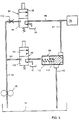
- FIG. 5 shows a schematic drawing of the hydraulic regulating system of the brake 34 according to an advantageous embodiment, which system can be regarded as forming part of the servo member 37.
- An oil pump 90 draws from a sump 91 hydraulic oil which is pumped out into a feed line 92 and via a throttle 110 to a first solenoid valve 93.
- the valve 93 is closed in a spring-loaded rest position 94.
- the valve 93 is electrically connected to and controlled by the control unit 32 and, upon activation, the valve 93 assumes an open position 95, and the hydraulic oil is conveyed further to a brake line 96 directly connected to the turbine brake 34.
- Also coupled to the brake line 96 is a branch line 97 which is connected to a pressure- regulating valve 99.
- the pressure- regulating valve is also connected to the feed line 92 via a line 103, which line 103 comprises a second solenoid valve 98.
- This valve has a spring- loaded closed rest position 100 and an open activated position 101.
- the second solenoid valve 98 too is connected to the control unit 32 and is activated by the latter.
- the pressure-regulating valve 99 comprises a pressure-regulating piston 113, which regulates the flow of oil from the branch line 97 to the return line 102, in order thereby also to regulate the pressure at which the oil is conveyed to the brake 34.
- the piston 113 is shown in Figure 5 in a closed position, in which the piston 113 is displaced towards its right-hand end position under the action of a compression spring 112.
- the function of the hydraulic regulating system is as follows. In the position of the valves 93, 98 and 99 as shown in Figure 5, oil is drained from the brake to the sump 91, and the brake is therefore not activated. Upon activation of the first valve 93, on the other hand, the brake is supplied with oil, which is thus pressurised. However, oil is also conveyed via the branch line 97 to the pressure-regulating valve 99, in which it acts on the right-hand side of the regulating piston 113 and displaces the piston 113 to an open position, counter to the action of the spring 112. Oil from the brake line 96 is thus conveyed on to the return line 102 and onwards to the sump 91.
- the compression spring 112 and the design of the piston 113 are dimensioned so as to limit the oil pressure which can be maintained in the brake line 96 to a low pressure. This pressure is too low for the brake 34 to be able to carry out any braking work. On the other hand, this pressure is sufficient for the discs in the brake 34 to be placed against each other and for play to be taken up.
- This pressure is dimensioned sufficiently high for the discs in the brake 34 to be placed against each other and to carry out braking work. It is assumed that the oil pump 90 itself comprises members regulating the maximum pressure which the pump 90 is able to provide, which pressure is identical to the maximum pressure which can be conveyed to the brake 34. It is also assumed that the pump 90 comprises members which protect the pump against overloading in the case where both solenoid valves 93 and 98 are closed.
- the following are given as examples of suitable low and high oil pressures which can occur in the closed and open positions, respectively, of the regulating piston 113.
- the low pressure which is used for bringing the discs together should be lower than 1 bar, but advantageously less than 0.5 bar. According to an advantageous embodiment, this pressure is chosen at about 0.2 bar.
- the high pressure which is used for applying the brake in such a way that it carries out braking work should be at least a power of 10 higher than the low pressure, and advantageously about 200% or more higher. When the brake is to carry out braking work, the brake pressure is in itself of less interest. The essential point is that the brake is able to generate a certain desired braking torque.
- This braking torque must be sufficiently high to be able to hold completely the input shaft 25 of the gearbox 6 when the drive engine 2 is idling and the torque converter 5 is at least partially filled with oil.
- the brake 34 should be dimensioned to generate a braking torque of at least about 2,000 Nm. With suitable dimensioning of the brake 34, it should be possible to obtain this braking torque at a brake pressure of about 5 bar, which thus corresponds to the high oil pressure which is mentioned above. With this dimensioning, the low oil pressure of 0.2 bar corresponds to a braking torque of about 80 Nm. This braking torque should advantageously be less than 100 Nm, which it therefore is.
- the second solenoid valve 98 can be designed as a proportional valve by means of which the pressure conveyed to the left-hand side of the regulating piston 113 can be continuously regulated.
- a proportional valve can have the same basic construction as the valve 98 illustrated, but the activation is effected by means of signals in the form of pulses.
- the pressure which is conveyed to the brake can also be regulated continuously. This can be of value in more developed embodiments of the invention.
- the proportional valve can of course be designed in other ways well known per se. In simpler forms of the invention, however, the application of the brake 34 does not need to take place in several steps, but instead can take place in a single step.
- the control unit 32 is electrically connected to a number of sensors for detecting different vehicle states.
- one sensor 40 arranged on the brake pedal of the vehicle is used for detecting a braking state
- one sensor is used both for detecting the speed of the vehicle 1 and for detecting when the vehicle 1 is stationary
- one sensor 44 for detecting the rotational speed of the output shaft 10 of the engine 2
- one sensor 43 for detecting the rotational speed of the input shaft 25 of the gearbox 6, and one sensor 42 for detecting the rotational speed of the output shaft 26 of the gearbox 6.
- the last-mentioned sensor 42 can be the same sensor as detects the vehicle speed.
- a sensor 45 on the accelerator pedal of the vehicle which emits a signal representing a drive torque desired by the driver.
- Several of the sensors can consist of existing vehicle sensors intended to be used also for other purposes in the vehicle.
- a drive mode selector which is connected to the control unit 32 and is actuated manually by the driver.
- the driver can select at least one forward drive mode D, one reverse drive mode R and a neutral position N.
- the forward drive mode D there is an automatic selection of gear and an automatic shifting of the gearbox 6.
- the drive mode selector can in addition be designed for manual gear selection and gear-changing.
- the control unit 32 also comprises checking members which check whether the gear selected by the driver and whether the gear-changing desired by the driver are feasible with regard to the actual driving conditions.
- the drive mode selector comprises a sensor 50 detecting which mode the driver has selected, this sensor 50 being connected to the control unit 32.
- the control unit 32 is moreover connected to sensors (not shown in Figure 2) detecting the rotational speed of the pump shaft 18, which gear position has been engaged in the gearbox 6, which torque the engine 2 is providing, and sensors which detect whether the brakes 24, 34 and 38 in the planetary gear 4, on the turbine shaft 21 and on the output shaft of the gearbox 6, respectively, are activated or not.
- the control unit 32 emits output signals to different servo members for activating different units in the transmission 3, as emerged from the above description.
- the control unit 32 is also connected to an engine control unit 46 by means of which the engine 2 can be regulated.
- the engine control unit 46 is advantageously designed to regulate the fuel injection quantity, by which means the speed of the engine 2 can be regulated.
- fuel injection can again be regulated, but it is also possible, at least within certain areas, to control the ignition system of the engine for speed-regulating purposes.
- the engine control unit 46 should advantageously be of a relatively accurate type, allowing the engine speed to be regulated with great accuracy.
- the control unit 32 uses signals from the accelerator sensor 45 in order to control the engine 2.
- the vehicle 1 is thus provided with electric accelerator control, so-called electric accelerator, which means that the engine can be controlled regardless of the driver's accelerator pedal position. Since such electrical engine-regulating systems are well known per se, they too are not dealt with in the description.
- the control unit 32 is also designed to regulate, via a servomember 47, the activation of the brake 24 of the planetary gear 4, the servo member 37 for regulating the brake 34 on the turbine shaft 21, a servo member 48 for regulating the retarder 38 on the output shaft 26 of the gearbox 6, and servo members and regulating members (not shown) included in the hydraulic system of the torque converter 5 for regulating the oil supply and oil pressure in the torque converter 5.
- This system does not form part of the present invention either and is therefore not dealt with further in the description.
- the vehicle 1 is assumed initially to be stationary, with the engine 2 in an idling position and its output shaft 10 rotating.
- the planetary gear brake 24 is assumed to be disengaged so that the sun wheel 15 of the planetary gear 4 is rotating, i.e. the planetary gear 4 has its low-gear range engaged.
- the brake 34 on the turbine shaft 21 is assumed to be disengaged.
- the gearbox 6 is assumed to be in a neutral position, so that it produces a drive power interruption.
- the output shaft 26 of the gearbox 6 is assumed, like the drive wheels 9, to be stationary. It is also assumed that the control unit 32 has detected these states.
- the driver wishes to start driving the vehicle forwards, he activates the drive mode selector 50 by moving a manoeuvring column on the latter from the neutral position N to the drive position D. In Figure 3, this is illustrated by an initial step 51.
- a fourth step 54 the speed n t of the turbine shaft is detected by means of the sensor 43. If the sensor 43 detects that the speed n t is equal to zero, the control unit 32 emits a signal to the servo members 33 on the gearbox 6 to engage a gear. This is illustrated by a fifth step 55 in Figure 3. This gear is a starting gear and, moreover, the first gear position of the gearbox 6 for forward drive. If the sensor 43 does not detect that the speed of the turbine shaft 21 is equal to zero, the control unit 32 does not emit any signal for gear engagement.
- the gearbox includes sensors detecting which gear position 6 has been engaged, and also a sensor detecting when the neutral position of the gearbox 6 is engaged.
- the last-mentioned sensor can be omitted, and instead the first-mentioned sensors are used for detecting whether the neutral position is engaged. The absence of any detection of a gear being engaged is thus used for detecting that the neutral position is engaged. If the sensor in question detects that the gear position in question is engaged, the gear engagement is complete, illustrated in Figure 3 by a sixth step 56. The whole procedure for gear engagement is thus complete, and the control unit 32 emits signals to release the turbine brake 34 in a seventh step 57.
- the vehicle 1 is thus ready for driving, which is illustrated by an eighth step 58.
- the driver can regulate the desired drive torque by means of the accelerator pedal and can start off and drive the vehicle 1.
- the turbine shaft 21 has been stopped, which has meant that the input shaft 25 of the gearbox 6 has also been stationary. Gear engagements can therefore be carried out without additional requirements for any synchronisation arrangements in the gearbox 6.
- the gearbox 6 can therefore be of the so-called unsynchronised type, which means that it is both simple and inexpensive and can have small dimensions.
- the turbine shaft 21 has been stopped while, in contrast, the pump shaft 18 has been driven by the engine 2. A deliberate slipping has therefore taken place in the torque converter 5 between the impeller 17 and the turbine wheel 19.
- the control unit 32 waits for this to occur. If no detection is obtained within a certain predetermined time T0, this is an indication that gear engagement cannot take place. This can be caused, for example, by the fact that the clutch members 31, which are included in the gearbox for ensuring engagement of the gear positions, have assumed rotational positions relative to each other which do not permit coupling together.
- the clutch members 31 of dimensionally fixed type, for example claw clutches, permit coupling together only when those parts which are to be coupled together are situated in certain relative rotational positions.
- FIG. 3 shows that a time calculation is carried out in a ninth step 59, and if the time T in accordance with the above has exceeded the predetermined time T0, the control unit 32 emits a signal to interrupt engagement of the gear and instead to engage the neutral position of the gearbox 6. This is illustrated by a tenth step 60.
- An eleventh step 61 involves detecting whether the gear is disengaged and, thus, whether the neutral position is engaged. If this is the case, the control unit 32, in a twelfth step 62, emits a signal to release the turbine brake 34. In this way, the impeller 17 in the torque converter 5 is able to drive the turbine wheel 19, with the result that the turbine shaft 21 begins to rotate.
- a thirteenth step 63 involves detecting whether the turbine shaft 21 is actually rotating. When the control unit 32 has received via the sensor 43 an indication that the turbine shaft 21 is rotating, i.e. that the turbine shaft speed n t is not equal to zero, a new attempt is made to engage the gear, which attempt is begun by once more activating the turbine brake 34.
- the driver can start the vehicle 1. He can regulate the desired drive torque in a conventional manner by means of the accelerator pedal. As the planetary gear brake 24 is disengaged, the drive torque of the engine 2 on the output shaft 10 is divided up in the planetary gear 4. Part of the torque is transmitted mechanically and part is transmitted hydraulically via the torque converter 5 to the input shaft 25 of the gearbox. Since in this way only part of the torque of the engine 2 passes via the torque converter 5, it is possible to dimension the planetary gear 4, the torque converter 5 and the first gear of the gearbox 6 in such a way that the vehicle 1 can reach a relatively high speed before gear-changing is again required.
- the torque converter 5 initially acts in a conventional manner as a torque amplifier.
- the control unit 32 detects that the vehicle has reached a certain speed, a signal is emitted to the servo member 47 to activate the planetary gear brake 24.
- the sun wheel 15 is thus locked and its rotation stops.
- a slipping initially takes place in the planetary gear brake 24 and this gear-changing takes place without drive power interruption, since no gear-changing is carried out in the gearbox 6.
- the planetary gear 4 thereafter acts as an overdrive gear since the speed of its first output shaft 14 is higher than the speed of the input shaft 11.
- the changing-up takes place in the gearbox 6 automatically in accordance with the basic flow diagram shown in Figure 4.
- Such a requirement can be detected by the control unit 32 with the aid of, inter alia, the speed sensors 42, 43 on the output shaft 26 and input shaft 25, respectively, of the gearbox 6, and signals from the engine control unit 46.
- the control unit 32 In an initial step 71 it is assumed that the control unit 32 has detected a changing-up requirement.
- the control unit 32 emits a signal which activates the first solenoid valve 93, while the second solenoid valve 98 remains in its closed rest position 100. In this way oil is conveyed to the turbine brake 34.
- step 72 the control unit 32 emits signals to the engine control unit 46 in order to regulate the torque M of the engine 2 to zero.
- Such a reduction of the engine torque advantageously takes place in accordance with a predetermined ramp function.
- step 73 involves detecting whether the engine torque M is equal to zero, or is sufficiently near zero with regard to possible tolerances.
- step 74 the control unit 32 emits a signal to the servo member 33 of the gearbox 6 to disengage the gear which is engaged and to engage instead the neutral position.
- step 75 involves detecting whether this has taken place, and, if the gear is disengaged, the control unit 32 in a step 76 emits a signal to activate the second solenoid valve 98 so that this assumes its open position 101.
- oil is also conveyed to the pressure-regulating valve 99 and displaces the piston 113 to its right-hand end position so that the connection of the line 97 to the return line 102 is interrupted.
- the oil which is conveyed to the brake 34 therefore reaches a high pressure, which is sufficient for the discs of the brake 34 to be able to carry out braking work in order to reduce the rotational speed of the input shaft 25 of the gearbox.
- the control unit 32 In order to reduce the speed of the turbine shaft 21 even more quickly, the control unit 32 also emits a signal to the engine control member 46 in order to activate an engine brake function in a step 77.
- This engine brake function can be achieved in practice by the throttle of the engine 2 being closed and/or by suitable regulation of its fuel injection. In those cases where the engine 2 is additionally equipped with a so-called exhaust brake, this brake can also advantageously be designed to be activated by the control unit at the same time as the engine brake function, in order to retard the engine shaft 10 even more quickly.
- the control unit 32 in step 79 emits a signal to release the turbine brake 34.
- the control unit 32 in a step 80 emits a signal to the engine control unit 46 which regulates the engine speed n m to a speed corresponding to a synchronous speed n s in the gearbox 6 for the gear which is to be engaged.
- the control unit 32 includes a memory unit in which values are stored for the different gear changes which are possible for the gearbox 6. With the aid of these values, the synchronous speed n s for each gear can be calculated as a function of the actual speed of the output shaft 39 of the gearbox 6. This control of the engine speed n m is achieved in practice by regulating the throttle of the engine and/or the fuel injection.
- Step 81 the control unit 32 emits signals to the servo member 33 of the gearbox 6 in order to engage the new gear in question, illustrated by step 82.
- Step 83 involves detecting whether the gear is actually engaged and, if this is the case, the changing-up is complete, as illustrated by step 84.
- the driver can then regulate the torque of the engine 2 and the speed at which the vehicle 1 is to be driven.
- the engine 2 has been controlled entirely by means of signals from the control unit 32.
- the activation of the accelerator pedal by the driver during the gear-changing procedure has therefore not affected the engine control.
- the transition between the automatic regulation of the engine control by the control unit 32 and the regulation by the driver via the accelerator pedal should take place in accordance with a certain ramp function so that driving will be free from jolts.
- Further changing-up in the gearbox 6 takes place in a completely analogous manner to what has been described above with reference to Figure 4.
- the planetary gear 4 is in its high gear position, i.e. the planetary gear 4 acts as an overdrive gear and the torque converter 5 does not contribute to the torque transfer in the transmission.
- control unit 32 detects a requirement for changing-down, this is carried out in accordance with a procedure rather like that which is initiated on changing-up. When changing-down, however, it is instead necessary to accelerate the input shaft 25 of the gearbox 6 before a new gear is engaged.
- the flow diagram shown in Figure 4 is also applicable to changing-down as regards steps 72 to 75.
- step 76 the turbine brake will not be activated.
- step 77 the engine 2 will not be controlled by an engine brake function, but instead the engine 2 will be controlled in such a way that its speed increases. When the speed of the engine 2 exceeds a certain speed, the engine 2 is controlled to a synchronous speed in the same way as in step 80. Thereafter, the procedure is the same as in steps 81 to 84.
- the control unit 32 When changing down to lowest gear, the starting gear, when the first gear position of the stepped gearbox and the low gear range of the planetary gear are engaged, the control unit 32 also emits signals for regulating the planetary gear brake 24 in a manner analogous to that described previously. Should the vehicle 1 be braked quickly, the changing-down takes place in such a way that the starting gear is engaged before the vehicle 1 is completely stationary. As has been described above, when the vehicle is stationary, the impeller 17 of the torque converter 5 is driven, while its turbine wheel 19 is stationary.
- Engagement of the reverse gear of the gearbox 6 is effected in a manner analogous to that which has been described above for engagement of the starting gear. Since, at least as regards vehicles for road traffic, there is only a limited requirement for reversing the vehicle, there is no need to disengage the torque converter 5 during reversing. Only the reverse gear and the first gear in the gearbox 6 must be dimensioned for the increased torques which can occur on account of the torque increase of the torque converter 5. The other gears in the gearbox 6 need only be dimensioned on the basis of the torques which the engine 2 is able to provide via the planetary gear 4. Since the planetary gear 4 in these cases acts as an overdrive gear, the torque from the engine 2 is reduced before it is transmitted to the input shaft 25 of the gearbox 6.
- An important advantage obtained in an advantageous embodiment of the present invention is that there is no need at all for any separate clutch in order to create drive power interruption between the engine 2 and the gearbox 6 during the time in which gear-changing is taking place in the gearbox 6.
- a drive power interruption is obtained in the transmission 3. If in this respect the speed of the vehicle were to be too low, there would be a risk of the vehicle, for example a heavily loaded vehicle on an uphill incline, coming to a halt before a new gear was engaged.
- the planetary gear 4 according to the illustrated advantageous embodiment and the torque converter 5 allow the vehicle 1 to reach a comparatively high speed before there is a need for changing up in the gearbox 6, it has been possible for this risk to be eliminated at least under the most common driving conditions. Should the vehicle 1 unexpectedly have stopped or its speed have been reduced during the gear- changing procedure, the starting gear is automatically engaged and driving can be immediately resumed or continued at low speed.
- Gearboxes for heavy vehicles often comprise a so-called range section with a low-speed range and a high-speed range.
- the transmission according to the invention dispenses with the need to change gear in the low-speed range, and the need for a range gearbox is therefore also dispensed with. This affords great advantages.
- the turbine brake 34 can also be used together with the ordinary brake system of the vehicle 1 in order to improve the braking capacity of the vehicle.
- the control unit 32 obtains a signal from the brake pedal sensor 40 indicating that a braking procedure is ongoing, and the control unit 32 can emit a new signal to activate the turbine brake 34.
- the method described has related primarily to a normal driving procedure.
- the control unit 32 can additionally be designed to regulate the transmission, using signals other than have been mentioned, for detecting errors in the system or the occurrence of abnormal driving situations.
Landscapes
- Engineering & Computer Science (AREA)
- General Engineering & Computer Science (AREA)
- Mechanical Engineering (AREA)
- Control Of Transmission Device (AREA)
- Control Of Fluid Gearings (AREA)
- Structure Of Transmissions (AREA)
Abstract
Description
- The present invention relates to a transmission for a vehicle in accordance with the preamble of attached Patent Claim 1. The invention also relates to a method for regulating a transmission in accordance with the preamble of attached Patent Claim 8.
- Transmissions for use in vehicles generally comprise a gearbox of some type or another in order to permit driving under varying conditions. Various main types of gearboxes are known. One type consists of hydraulic gearboxes incorporating a hydraulic torque converter coupled in series to a gearbox comprising a number of planetary gears. The advantages of this type are that the regulation is effected automatically, the gear-changing can take place without drive power interruption, and the driver does not have to manoeuvre any clutch. In addition, on starting, the driver can easily regulate the desired drive torque by means of regulating only the accelerator pedal and, moreover, a high starting torque is obtained. The disadvantages are that these gearboxes are relatively complicated and therefore also expensive Furthermore, they exhibit relatively high energy losses.
- Another type of gearbox consists of a mechanical stepped gearbox. In this, there are arranged, on parallel shafts, a number of pairs of gear wheels which, by means of selective engagement, give different gears. When changing gear, the driver usually has to operate a clutch manually in order to produce a drive power interruption from the vehicle engine. This type of gearbox exhibits relatively small friction losses and it is considerably cheaper to manufacture than a hydraulic gearbox of the type described above.
- In addition to these two main types of gearboxes, there are other variants of the same. For the purpose of improving the starting torque especially in heavy vehicles, it is known, in the case of stepped gearboxes, to arrange a hydraulic torque converter between a drive engine and a clutch. Such a construction means that the clutch is also exposed to high torques when the torque converter is engaged. The clutch is not usually dimensioned for these high torques, with the consequence that it should not be manoeuvred when the torque converter is engaged. The result of this is that such a transmission requires a special mode of driving and requires that the driver be trained for this, since otherwise the clutch plate risks being overloaded.
- Another alternative transmission is described in British Patent Specification GB-A-2,193,766. In this case, a hydraulic torque converter is coupled together with a stepped gearbox. The torque converter is connected to a drive engine via two separate clutch plates. Upon activation of the one clutch plate, all the drive power is transmitted from the drive engine via the torque converter to the stepped gearbox. Upon activation of the other clutch plate, all the drive power is transmitted from the drive engine via a free wheel directly to the stepped gearbox. This transmission functions such that, upon starting-up and with the vehicle stationary, both the clutch plates are disengaged in order to produce a drive power interruption and to permit manoeuvring of the stepped gearbox so that a starting gear can be engaged. Thereafter, the one clutch plate is activated, by which means the torque converter is engaged and drive power is transmitted from the engine to the output shaft of the gearbox. When the vehicle has reached a certain speed, the first clutch plate is disengaged and the second clutch plate is activated instead, by which means the drive power is transmitted directly from the engine to the input shaft of the gearbox. Upon continued increase of speed, the stepped gearbox can be shifted after a certain time, this taking place with the aid of different clutches in the gearbox. When the vehicle has come to a halt, it is necessary to interrupt the drive power connection, which is effected by disengaging the clutch plate in question. In order to permit gear-changing during travel, it is necessary to control the engine speed in a suitable manner in order to produce or at least facilitate synchronisation before a new gear can be engaged.
- American Patent Specification US-A-3,834,499 illustrates a mechanical gearbox which is connected via a conventional clutch to a drive engine. The gearbox comprises an electronic synchronisation arrangement which, inter alia, regulates the engine speed before a change of gear. For the purpose of speeding up the synchronisation, this arrangement also comprises a brake which permits rapid reduction in the speed of the input shaft of the gearbox.
- The present invention aims to produce a new type of transmission primarily intended for use in heavy vehicles such as lorries, which combines the advantages of known types but which does not exhibit their respective disadvantages. More specifically, the aim is to produce an automatic transmission which does not require the driver to operate any clutch on starting-up and when changing gear, which can provide a high and easily controllable torque at least when starting-up, and which allows a number of gears to be selected so that the engine will be able to be driven around an optimum engine speed. Furthermore, the aim is to reduce the friction losses via the transmission and to design the transmission in a simple manner and at a relatively low cost.
- These aims are achieved by virtue of the fact that the transmission according to the invention is designed in accordance with what is stated in the characterising clause of attached Patent Claim 1. According to the invention, by arranging a brake which can firmly lock the input shaft of the gearbox, it is possible for gear engagement to be carried out upon starting-up, even when the drive engine of the vehicle is running, without the need to use conventional friction coupling for drive power interruption. According to an advantageous embodiment of the invention, no mechanical clutch is therefore required for producing drive power interruption between the shafts during gear-changing. In this way, it has been possible for the regulation of a mechanical gearbox to be automated by simple means.
- According to a further advantageous embodiment of the invention, by arranging a planetary gear in front of the torque converter, it is possible to divide the drive torque up so that only part of the overall drive torque is transmitted via the torque converter. This means that the load on the torque converter is relatively small. This in turn means that it is possible to accelerate the vehicle to a relatively high speed from start-up before the stepped gearbox needs to be shifted. For reasons of fuel economy, modern diesel engines for use in heavy vehicles are dimensioned so as to be driven at a relatively low engine speed and are furthermore often dimensioned so as to be driven optimally within a narrow range of speed. The advantageously arranged planetary gear means that the speed is changed up before the torque converter, which thereby improves the preconditions for the torque converter being driven optimally in spite of a low engine speed. A method for regulating a transmission according to the invention is stated in the characterising clause of attached Patent Claim 8. Further advantages and features characterising the invention will emerge from the subsequent description of an exemplary embodiment of the invention.
- In the description, reference is made to the attached drawings in which
- Figure 1
- shows diagrammatically a vehicle with a transmission according to the invention,
- Figure 2
- shows diagrammatically the transmission according to Figure 1,
- Figure 3
- shows a flow diagram of a method according to the invention for engagement of a starting gear, and
- Figure 4
- shows a flow diagram of a method for changing up to higher gears.
- Figure 5
- shows a hydraulic coupling circuit for regulating a brake included in the transmission.
- Attached Figure 1 shows diagrammatically a vehicle 1 in the form of a lorry. However, the invention is applicable to all types of vehicles, both heavy vehicles, such as lorries and buses, and lighter vehicles, such as passenger cars. The vehicle 1 comprises a
drive engine 2, expediently an internal combustion engine, which transmits drive power to thedrive wheels 9 of the vehicle via a transmission 3. The transmission 3 comprises the following main units, in order from the engine: namely a planetary gear 4, ahydraulic torque converter 5, astepped gearbox 6, a hydraulic retarder 7, and a bevel gear 8 which finally transmits the drive power to thedrive wheels 9. These units are connected to each other in a conventional manner via a number of shafts and in a way which will emerge more clearly from the description which follows.
Attached Figure 2 shows a more detailed but nevertheless diagrammatic representation of those parts of the transmission 3 according to Figure 1 which are essential to the present invention. Theengine 2 is shown in Figure 2 with anoutput shaft 10 which in theengine 2 is connected to its crankshaft and its flywheel (not shown) via a resilient carrier. This carrier is an elastic transfer element for compensating for the pulsating vibrations of the crankshaft caused by the different ignition times for the different cylinders of the engine. The carrier ensures that theoutput shaft 10 rotates evenly and without pulsations which would otherwise cause noise in subsequent gearwheel transmissions. Since resilient carriers are well known per se in conjunction with vehicle transmissions, the description will not contain details of their design. The planetary gear 4 comprises aninput shaft 11 which is connected at one end to theoutput shaft 10 of theengine 2 and is connected at the other end to aplanetary wheel holder 12. The planetary gear 4 furthermore comprises aring wheel 13 connected to afirst output shaft 14 of the planetary gear 4 and asun wheel 15 connected to asecond output shaft 16 of the planetary gear 4. Thesecond output shaft 16 of the planetary gear 4 is advantageously designed as a tubular shaft which is arranged around thefirst output shaft 14 of the planetary gear 4. The planetary gear 4 is not in itself necessary for utilising the present invention, but it should be included in an advantageous embodiment, since it affords great advantages as will emerge from the description which follows. - The
hydraulic torque converter 5 comprises animpeller 17 connected to aninput shaft 18, hereinafter called thepump shaft 18. Thetorque converter 5 also comprises aturbine wheel 19 which is connected, via afree wheel 20, to anoutput shaft 21, hereinafter called theturbine shaft 21. In this case, thefree wheel 20 is arranged in such a way that only drive power in the normal direction of rotation of theengine 2 can be transmitted from theturbine wheel 19 to theturbine shaft 21. Thetorque converter 5 moreover comprises astator 22 firmly connected to thehousing 23 of thetorque converter 5 in a conventional manner. Arranged between the planetary gear 4 and thetorque converter 5 is abrake 24 which is connected to thesecond output shaft 16 of the planetary gear 4 and can thus also be regarded as firmly connected to thepump shaft 18 of thetorque converter 5. Thebrake 24 is used in a high gear position of the planetary gear 4, when thebrake 24 is activated and firmly locks thesun wheel 15 of the planetary gear 4. All the torque is thus transmitted mechanically from theinput shaft 11 of the planetary gear 4 to itsfirst output shaft 14. In a low gear position of the planetary gear 4, on the other hand, thebrake 24 is not activated, in which respect the torque is divided up in the planetary gear 4 (which then acts as a differential gear) into a part which is transmitted to thefirst output shaft 14 and a part which is transmitted to thesecond output shaft 16. In the latter case, part of the torque is transmitted to thepump shaft 18 of thetorque converter 5, then via thetorque converter 5 and further via thefree wheel 20 to theturbine shaft 21. In this way, part of the torque from theengine 2 is thus transmitted mechanically to theturbine shaft 21 and the other part of the torque is transmitted hydraulically to theturbine shaft 21. - The stepped
gearbox 6 comprises aninput shaft 25, amain shaft 26 and aside shaft 27, whichshafts main shaft 26, and similarly the output shaft of thegearbox 6. The illustratedgearbox 6 comprises six pairs ofgear wheels 28, of which one pair cooperates with the reverse gear. Thegearbox 6 therefore has five gear positions for forward drive and one gear position for reverse drive. Thegearbox 6 comprises a number ofclutches 31 by means of which the respective gear wheel pairs 28 can be selectively engaged in order to form the different gear ratios. Theclutches 31 comprise clutch halves for stable coupling together with each other. Theclutches 31 are operated automatically under the action of acontrol unit 32 viaservo members 33. Thegearbox 6 is therefore a side-shaft gearbox which is automatically controlled by thecontrol unit 32. Theservo members 33 can advantageously consist of hydraulic or pneumatic piston-cylinder units which act on shifter forks in thegearbox 6. As will emerge from the description, this means that thegearbox 6 can be of the so-called unsynchronised type, by which is meant here that therespective clutches 31 are without individual synchronisation members. - Characteristic of the illustrated arrangement, which represents an advantageous embodiment, is the fact that the
input shaft 25 of the gearbox is firmly connected to theturbine shaft 21 and that the transmission 3 has no mechanical clutch for producing drive power interruption between theengine 2 and thegearbox 6 during changing in thegearbox 6 and on engagement of the starting gear. In an alternative embodiment, however, the arrangement can also comprise a conventional clutch, for example in the form of a friction clutch between theinput shaft 25 of the gearbox and theturbine shaft 21. - In alternative embodiments, the stepped gearbox can comprise a number of side shafts. The stepped gearbox can also be based on entirely different types of gearboxes, in which the different gears can be selectively engaged by means of dimensionally fixed clutch elements.
- Arranged between the
gearbox 6 and thetorque converter 5 is abrake 34. This is designed as a disc brake with a number of discs arranged on and firmly connected to theinput shaft 25 of thegearbox 6 and with a number of rotationally-fixed discs. An electricallyactuable servo member 37 is designed, upon activation, to convey hydraulic oil to thebrake 34 in order thereby to create a brake pressure. Theservo member 37 is electrically connected to theelectrical control unit 32 for control of the same in accordance with what is described in greater detail below. - In an alternative embodiment, the
brake 34 can instead be mounted on a side shaft which is connected in a drive power- transmitting manner to theinput shaft 25 or theturbine shaft 21. - Arranged on the
output shaft 26 of the gearbox is a brake designed as ahydrodynamic retarder 38 which, upon activation, brakes theoutput shaft 26 in a conventional manner. The hydraulic system which is required for theretarder 38 can advantageously be combined with that which is required for thetorque converter 5. However, since these hydraulic systems can be regarded as being of conventional construction and since it is not necessary to know their detailed design for an understanding of the present invention, they are not included in the description. - The
output shaft 26 of thegearbox 6 is moreover connected in a conventional manner via acardan shaft 39 to the bevel gear 8 for onward transfer of drive power to thedrive wheels 9 of the vehicle 1. This part too of the transmission 3 is of conventional design. - Figure 5 shows a schematic drawing of the hydraulic regulating system of the
brake 34 according to an advantageous embodiment, which system can be regarded as forming part of theservo member 37. Anoil pump 90 draws from asump 91 hydraulic oil which is pumped out into afeed line 92 and via athrottle 110 to afirst solenoid valve 93. Thevalve 93 is closed in a spring-loadedrest position 94. Thevalve 93 is electrically connected to and controlled by thecontrol unit 32 and, upon activation, thevalve 93 assumes anopen position 95, and the hydraulic oil is conveyed further to abrake line 96 directly connected to theturbine brake 34. Also coupled to thebrake line 96 is abranch line 97 which is connected to a pressure- regulatingvalve 99. This is also connected to thesump 91 via areturn line 102. The pressure- regulating valve is also connected to thefeed line 92 via aline 103, which line 103 comprises asecond solenoid valve 98. This valve has a spring- loadedclosed rest position 100 and an openactivated position 101. Thesecond solenoid valve 98 too is connected to thecontrol unit 32 and is activated by the latter. - The pressure-regulating
valve 99 comprises a pressure- regulatingpiston 113, which regulates the flow of oil from thebranch line 97 to thereturn line 102, in order thereby also to regulate the pressure at which the oil is conveyed to thebrake 34. Thepiston 113 is shown in Figure 5 in a closed position, in which thepiston 113 is displaced towards its right-hand end position under the action of acompression spring 112. - The function of the hydraulic regulating system is as follows. In the position of the
valves sump 91, and the brake is therefore not activated. Upon activation of thefirst valve 93, on the other hand, the brake is supplied with oil, which is thus pressurised. However, oil is also conveyed via thebranch line 97 to the pressure-regulatingvalve 99, in which it acts on the right-hand side of theregulating piston 113 and displaces thepiston 113 to an open position, counter to the action of thespring 112. Oil from thebrake line 96 is thus conveyed on to thereturn line 102 and onwards to thesump 91. This means that the oil pressure conveyed to thebrake 34 can only reach a relatively low value. Thecompression spring 112 and the design of thepiston 113 are dimensioned so as to limit the oil pressure which can be maintained in thebrake line 96 to a low pressure. This pressure is too low for thebrake 34 to be able to carry out any braking work. On the other hand, this pressure is sufficient for the discs in thebrake 34 to be placed against each other and for play to be taken up. - Upon activation of the
second solenoid valve 98 too, oil is conveyed again from thefeed line 92 to the pressure-regulatingvalve 99, in which the oil acts on the left-hand side of thepiston 113. In addition, as before, oil is conveyed via thebranch line 97 to the right-hand side of thepiston 113. The oil pressures acting on both sides of thepiston 113 are even and balance each other. Under the action of thespring 112, thepiston 113 is displaced towards its right-hand closed position. The connection between thebranch line 97 and thereturn line 102 is thus interrupted. The pressure which the oil reaches in thebrake line 96 thus comes to attain a high value which is limited only by the pressure which thepump 90 is able to provide. This pressure is dimensioned sufficiently high for the discs in thebrake 34 to be placed against each other and to carry out braking work. It is assumed that theoil pump 90 itself comprises members regulating the maximum pressure which thepump 90 is able to provide, which pressure is identical to the maximum pressure which can be conveyed to thebrake 34. It is also assumed that thepump 90 comprises members which protect the pump against overloading in the case where both solenoidvalves - The following are given as examples of suitable low and high oil pressures which can occur in the closed and open positions, respectively, of the
regulating piston 113. The low pressure which is used for bringing the discs together should be lower than 1 bar, but advantageously less than 0.5 bar. According to an advantageous embodiment, this pressure is chosen at about 0.2 bar. The high pressure which is used for applying the brake in such a way that it carries out braking work should be at least a power of 10 higher than the low pressure, and advantageously about 200% or more higher. When the brake is to carry out braking work, the brake pressure is in itself of less interest. The essential point is that the brake is able to generate a certain desired braking torque. This braking torque must be sufficiently high to be able to hold completely theinput shaft 25 of thegearbox 6 when thedrive engine 2 is idling and thetorque converter 5 is at least partially filled with oil. In the case of a heavy lorry, thebrake 34 should be dimensioned to generate a braking torque of at least about 2,000 Nm. With suitable dimensioning of thebrake 34, it should be possible to obtain this braking torque at a brake pressure of about 5 bar, which thus corresponds to the high oil pressure which is mentioned above. With this dimensioning, the low oil pressure of 0.2 bar corresponds to a braking torque of about 80 Nm. This braking torque should advantageously be less than 100 Nm, which it therefore is. - In an advantageous embodiment of the hydraulic system shown in Figure 5, the
second solenoid valve 98 can be designed as a proportional valve by means of which the pressure conveyed to the left-hand side of theregulating piston 113 can be continuously regulated. Such a proportional valve can have the same basic construction as thevalve 98 illustrated, but the activation is effected by means of signals in the form of pulses. By virtue of the fact that the pressure on the left- hand side of theregulating piston 113 can be regulated in this way, the pressure which is conveyed to the brake can also be regulated continuously. This can be of value in more developed embodiments of the invention. The proportional valve can of course be designed in other ways well known per se. In simpler forms of the invention, however, the application of thebrake 34 does not need to take place in several steps, but instead can take place in a single step. - As has emerged from the above, a number of the units of the transmission 3 are connected to the
control unit 32. This is based on a microprocessor. Thecontrol unit 32 is electrically connected to a number of sensors for detecting different vehicle states. Of these sensors, onesensor 40 arranged on the brake pedal of the vehicle is used for detecting a braking state, one sensor is used both for detecting the speed of the vehicle 1 and for detecting when the vehicle 1 is stationary, onesensor 44 for detecting the rotational speed of theoutput shaft 10 of theengine 2, onesensor 43 for detecting the rotational speed of theinput shaft 25 of thegearbox 6, and onesensor 42 for detecting the rotational speed of theoutput shaft 26 of thegearbox 6. In practice, the last-mentionedsensor 42 can be the same sensor as detects the vehicle speed. There is also asensor 45 on the accelerator pedal of the vehicle, which emits a signal representing a drive torque desired by the driver. Several of the sensors can consist of existing vehicle sensors intended to be used also for other purposes in the vehicle. - There is in addition a drive mode selector which is connected to the
control unit 32 and is actuated manually by the driver. By means of the drive mode selector, the driver can select at least one forward drive mode D, one reverse drive mode R and a neutral position N. Upon engagement of the forward drive mode D, there is an automatic selection of gear and an automatic shifting of thegearbox 6. In alternative embodiments, the drive mode selector can in addition be designed for manual gear selection and gear-changing. In these cases, thecontrol unit 32 also comprises checking members which check whether the gear selected by the driver and whether the gear-changing desired by the driver are feasible with regard to the actual driving conditions. The drive mode selector comprises asensor 50 detecting which mode the driver has selected, thissensor 50 being connected to thecontrol unit 32. - The
control unit 32 is moreover connected to sensors (not shown in Figure 2) detecting the rotational speed of thepump shaft 18, which gear position has been engaged in thegearbox 6, which torque theengine 2 is providing, and sensors which detect whether thebrakes turbine shaft 21 and on the output shaft of thegearbox 6, respectively, are activated or not. - The
control unit 32 emits output signals to different servo members for activating different units in the transmission 3, as emerged from the above description. In addition, thecontrol unit 32 is also connected to anengine control unit 46 by means of which theengine 2 can be regulated. If theengine 2 consists of a diesel engine, theengine control unit 46 is advantageously designed to regulate the fuel injection quantity, by which means the speed of theengine 2 can be regulated. In the case where theengine 2 consists of an Otto engine, fuel injection can again be regulated, but it is also possible, at least within certain areas, to control the ignition system of the engine for speed-regulating purposes. However, theengine control unit 46 should advantageously be of a relatively accurate type, allowing the engine speed to be regulated with great accuracy. During normal driving, thecontrol unit 32 uses signals from theaccelerator sensor 45 in order to control theengine 2. The vehicle 1 is thus provided with electric accelerator control, so-called electric accelerator, which means that the engine can be controlled regardless of the driver's accelerator pedal position. Since such electrical engine-regulating systems are well known per se, they too are not dealt with in the description. - The
control unit 32 is also designed to regulate, via aservomember 47, the activation of thebrake 24 of the planetary gear 4, theservo member 37 for regulating thebrake 34 on theturbine shaft 21, aservo member 48 for regulating theretarder 38 on theoutput shaft 26 of thegearbox 6, and servo members and regulating members (not shown) included in the hydraulic system of thetorque converter 5 for regulating the oil supply and oil pressure in thetorque converter 5. This system does not form part of the present invention either and is therefore not dealt with further in the description. - The function of the described transmission 3 and a method for starting, gear-shifting and driving a vehicle 1 with such a transmission 3 are described hereinbelow, with reference to the flow diagrams shown in Figures 3 and 4. Of these, Figure 3 shows how a starting gear is engaged, and Figure 4 shows how changing-up is effected in the
gearbox 6. - The vehicle 1 is assumed initially to be stationary, with the
engine 2 in an idling position and itsoutput shaft 10 rotating. Theplanetary gear brake 24 is assumed to be disengaged so that thesun wheel 15 of the planetary gear 4 is rotating, i.e. the planetary gear 4 has its low-gear range engaged. Thebrake 34 on theturbine shaft 21 is assumed to be disengaged. Thegearbox 6 is assumed to be in a neutral position, so that it produces a drive power interruption. Theoutput shaft 26 of thegearbox 6 is assumed, like thedrive wheels 9, to be stationary. It is also assumed that thecontrol unit 32 has detected these states. When the driver wishes to start driving the vehicle forwards, he activates thedrive mode selector 50 by moving a manoeuvring column on the latter from the neutral position N to the drive position D. In Figure 3, this is illustrated by aninitial step 51. - In a
second step 52, a check is made as to whether the drive mode selector has adopted the drive mode D, using thesensor 50 provided for this purpose. If this has taken place, thissensor 50 emits a signal to thecontrol unit 32 to activate theservo members 37 on thebrake 34, hereinafter called the turbine brake, so that the latter brakes and locks theturbine shaft 21. This is achieved by means of bothsolenoid valves turbine brake 34. This is illustrated in Figure 3 by athird step 53. If, for any reason, thesensor 50 on the drive mode selector should not detect engagement of drive mode D, nothing happens until this has taken place. In afourth step 54, the speed nt of the turbine shaft is detected by means of thesensor 43. If thesensor 43 detects that the speed nt is equal to zero, thecontrol unit 32 emits a signal to theservo members 33 on thegearbox 6 to engage a gear. This is illustrated by afifth step 55 in Figure 3. This gear is a starting gear and, moreover, the first gear position of thegearbox 6 for forward drive. If thesensor 43 does not detect that the speed of theturbine shaft 21 is equal to zero, thecontrol unit 32 does not emit any signal for gear engagement. - As already mentioned, the gearbox includes sensors detecting which
gear position 6 has been engaged, and also a sensor detecting when the neutral position of thegearbox 6 is engaged. In a simpler embodiment, the last-mentioned sensor can be omitted, and instead the first-mentioned sensors are used for detecting whether the neutral position is engaged. The absence of any detection of a gear being engaged is thus used for detecting that the neutral position is engaged. If the sensor in question detects that the gear position in question is engaged, the gear engagement is complete, illustrated in Figure 3 by asixth step 56. The whole procedure for gear engagement is thus complete, and thecontrol unit 32 emits signals to release theturbine brake 34 in aseventh step 57. This is achieved by virtue of the fact that the activation of thesolenoid valves control unit 32 ceases, with the result that the feed of oil to theturbine brake 34 ceases and, instead, oil is drained from theturbine brake 34 to the sump. The vehicle 1 is thus ready for driving, which is illustrated by aneighth step 58. The driver can regulate the desired drive torque by means of the accelerator pedal and can start off and drive the vehicle 1. - During gear engagement, the
turbine shaft 21 has been stopped, which has meant that theinput shaft 25 of thegearbox 6 has also been stationary. Gear engagements can therefore be carried out without additional requirements for any synchronisation arrangements in thegearbox 6. Thegearbox 6 can therefore be of the so-called unsynchronised type, which means that it is both simple and inexpensive and can have small dimensions. Furthermore, during gear engagement, theturbine shaft 21 has been stopped while, in contrast, thepump shaft 18 has been driven by theengine 2. A deliberate slipping has therefore taken place in thetorque converter 5 between theimpeller 17 and theturbine wheel 19. - If, in the
sixth step 56 above, there is no detection of the gear being engaged, thecontrol unit 32 waits for this to occur. If no detection is obtained within a certain predetermined time T0, this is an indication that gear engagement cannot take place. This can be caused, for example, by the fact that theclutch members 31, which are included in the gearbox for ensuring engagement of the gear positions, have assumed rotational positions relative to each other which do not permit coupling together. Theclutch members 31 of dimensionally fixed type, for example claw clutches, permit coupling together only when those parts which are to be coupled together are situated in certain relative rotational positions. - Figure 3 shows that a time calculation is carried out in a
ninth step 59, and if the time T in accordance with the above has exceeded the predetermined time T0, thecontrol unit 32 emits a signal to interrupt engagement of the gear and instead to engage the neutral position of thegearbox 6. This is illustrated by atenth step 60. - An
eleventh step 61 involves detecting whether the gear is disengaged and, thus, whether the neutral position is engaged. If this is the case, thecontrol unit 32, in atwelfth step 62, emits a signal to release theturbine brake 34. In this way, theimpeller 17 in thetorque converter 5 is able to drive theturbine wheel 19, with the result that theturbine shaft 21 begins to rotate. Athirteenth step 63 involves detecting whether theturbine shaft 21 is actually rotating. When thecontrol unit 32 has received via thesensor 43 an indication that theturbine shaft 21 is rotating, i.e. that the turbine shaft speed nt is not equal to zero, a new attempt is made to engage the gear, which attempt is begun by once more activating theturbine brake 34. According to the flow diagram in Figure 3, a return is made to thethird step 53, after which the procedure described above is repeated. The rotation of theturbine shaft 21 and, thus, the rotation too of theinput shaft 25 of thegearbox 6 has hopefully resulted in theclutch members 31 in thegearbox 6 having been rotated to relative positions which permit coupling together. - Depending on what is detected in the
sixth step 56, either the gear engagement is completed or a new attempt at gear engagement is made. - If it is now assumed that gear engagement is completed, the driver can start the vehicle 1. He can regulate the desired drive torque in a conventional manner by means of the accelerator pedal. As the
planetary gear brake 24 is disengaged, the drive torque of theengine 2 on theoutput shaft 10 is divided up in the planetary gear 4. Part of the torque is transmitted mechanically and part is transmitted hydraulically via thetorque converter 5 to theinput shaft 25 of the gearbox. Since in this way only part of the torque of theengine 2 passes via thetorque converter 5, it is possible to dimension the planetary gear 4, thetorque converter 5 and the first gear of thegearbox 6 in such a way that the vehicle 1 can reach a relatively high speed before gear-changing is again required. This speed is at least so high that the vehicle 1, upon the next shifting in thegearbox 6, does not risk coming to a halt during the subsequent gear-changing procedure.
During the starting procedure above, thetorque converter 5 initially acts in a conventional manner as a torque amplifier. When thecontrol unit 32 detects that the vehicle has reached a certain speed, a signal is emitted to theservo member 47 to activate theplanetary gear brake 24. Thesun wheel 15 is thus locked and its rotation stops. During this first gear-changing, a slipping initially takes place in theplanetary gear brake 24 and this gear-changing takes place without drive power interruption, since no gear-changing is carried out in thegearbox 6. The planetary gear 4 thereafter acts as an overdrive gear since the speed of itsfirst output shaft 14 is higher than the speed of theinput shaft 11. - This too means that the vehicle 1, in accordance with the above, can reach a relatively high speed before the next change of gear is required, which gear-changing is carried out in the
gearbox 6. - However, when there is a need to change up in order to further increase the speed of the vehicle, the changing-up takes place in the
gearbox 6 automatically in accordance with the basic flow diagram shown in Figure 4. Such a requirement can be detected by thecontrol unit 32 with the aid of, inter alia, thespeed sensors output shaft 26 andinput shaft 25, respectively, of thegearbox 6, and signals from theengine control unit 46. In aninitial step 71 it is assumed that thecontrol unit 32 has detected a changing-up requirement. In asubsequent step 105, thecontrol unit 32 emits a signal which activates thefirst solenoid valve 93, while thesecond solenoid valve 98 remains in itsclosed rest position 100. In this way oil is conveyed to theturbine brake 34. However, oil is also conveyed via theline 97 to the pressure-regulatingvalve 99 in which the connection with thereturn line 102 is opened. The oil pressure conveyed to thebrake 34 can therefore only reach a low value in accordance with what has been described previously. This low oil pressure is thus intended to take up play between the discs of the brake and to bring together the discs at a low pressure. In thenext step 72, thecontrol unit 32 emits signals to theengine control unit 46 in order to regulate the torque M of theengine 2 to zero. Such a reduction of the engine torque advantageously takes place in accordance with a predetermined ramp function. The followingstep 73 involves detecting whether the engine torque M is equal to zero, or is sufficiently near zero with regard to possible tolerances. If this is the case, in thenext step 74 thecontrol unit 32 emits a signal to theservo member 33 of thegearbox 6 to disengage the gear which is engaged and to engage instead the neutral position. The followingstep 75 involves detecting whether this has taken place, and, if the gear is disengaged, thecontrol unit 32 in astep 76 emits a signal to activate thesecond solenoid valve 98 so that this assumes itsopen position 101. In this way, oil is also conveyed to the pressure-regulatingvalve 99 and displaces thepiston 113 to its right-hand end position so that the connection of theline 97 to thereturn line 102 is interrupted. The oil which is conveyed to thebrake 34 therefore reaches a high pressure, which is sufficient for the discs of thebrake 34 to be able to carry out braking work in order to reduce the rotational speed of theinput shaft 25 of the gearbox. - Since, in the
previous step 105, the brake was applied at a low pressure, the activation of the brake instep 76 can be effected quickly, with the result that braking of the input shaft is also effected quickly. This means that the time for a changing-up procedure can be quick, and the time in which the gear-changing causes drive power interruption can be reduced. In order to reduce the speed of theturbine shaft 21 even more quickly, thecontrol unit 32 also emits a signal to theengine control member 46 in order to activate an engine brake function in astep 77. This engine brake function can be achieved in practice by the throttle of theengine 2 being closed and/or by suitable regulation of its fuel injection. In those cases where theengine 2 is additionally equipped with a so-called exhaust brake, this brake can also advantageously be designed to be activated by the control unit at the same time as the engine brake function, in order to retard theengine shaft 10 even more quickly. - When the engine speed nm has dropped to or fallen below a predetermined speed N0 for each gear position in accordance with
step 78, thecontrol unit 32 instep 79 emits a signal to release theturbine brake 34. In addition, thecontrol unit 32 in astep 80 emits a signal to theengine control unit 46 which regulates the engine speed nm to a speed corresponding to a synchronous speed ns in thegearbox 6 for the gear which is to be engaged. It is assumed in this respect that thecontrol unit 32 includes a memory unit in which values are stored for the different gear changes which are possible for thegearbox 6. With the aid of these values, the synchronous speed ns for each gear can be calculated as a function of the actual speed of theoutput shaft 39 of thegearbox 6. This control of the engine speed nm is achieved in practice by regulating the throttle of the engine and/or the fuel injection. - When the engine speed nm has assumed the synchronous speed ns or, with regard to tolerances, is considered to be sufficiently near this, as illustrated by
step 81, thecontrol unit 32 emits signals to theservo member 33 of thegearbox 6 in order to engage the new gear in question, illustrated bystep 82.Step 83 involves detecting whether the gear is actually engaged and, if this is the case, the changing-up is complete, as illustrated bystep 84. By means of the accelerator pedal, the driver can then regulate the torque of theengine 2 and the speed at which the vehicle 1 is to be driven. - During the changing-up procedure described, the
engine 2 has been controlled entirely by means of signals from thecontrol unit 32. The activation of the accelerator pedal by the driver during the gear-changing procedure has therefore not affected the engine control. The transition between the automatic regulation of the engine control by thecontrol unit 32 and the regulation by the driver via the accelerator pedal should take place in accordance with a certain ramp function so that driving will be free from jolts. Further changing-up in thegearbox 6 takes place in a completely analogous manner to what has been described above with reference to Figure 4. During all gear-changes carried out in thegearbox 6, the planetary gear 4 is in its high gear position, i.e. the planetary gear 4 acts as an overdrive gear and thetorque converter 5 does not contribute to the torque transfer in the transmission. - If, on the basis of the vehicle parameters sensed, the
control unit 32 detects a requirement for changing-down, this is carried out in accordance with a procedure rather like that which is initiated on changing-up. When changing-down, however, it is instead necessary to accelerate theinput shaft 25 of thegearbox 6 before a new gear is engaged. The flow diagram shown in Figure 4 is also applicable to changing-down as regards steps 72 to 75. - In contrast, in
step 76 the turbine brake will not be activated. Likewise, instep 77, theengine 2 will not be controlled by an engine brake function, but instead theengine 2 will be controlled in such a way that its speed increases. When the speed of theengine 2 exceeds a certain speed, theengine 2 is controlled to a synchronous speed in the same way as instep 80. Thereafter, the procedure is the same as insteps 81 to 84. - When changing down to lowest gear, the starting gear, when the first gear position of the stepped gearbox and the low gear range of the planetary gear are engaged, the
control unit 32 also emits signals for regulating theplanetary gear brake 24 in a manner analogous to that described previously. Should the vehicle 1 be braked quickly, the changing-down takes place in such a way that the starting gear is engaged before the vehicle 1 is completely stationary. As has been described above, when the vehicle is stationary, theimpeller 17 of thetorque converter 5 is driven, while itsturbine wheel 19 is stationary. - Engagement of the reverse gear of the
gearbox 6 is effected in a manner analogous to that which has been described above for engagement of the starting gear. Since, at least as regards vehicles for road traffic, there is only a limited requirement for reversing the vehicle, there is no need to disengage thetorque converter 5 during reversing. Only the reverse gear and the first gear in thegearbox 6 must be dimensioned for the increased torques which can occur on account of the torque increase of thetorque converter 5. The other gears in thegearbox 6 need only be dimensioned on the basis of the torques which theengine 2 is able to provide via the planetary gear 4. Since the planetary gear 4 in these cases acts as an overdrive gear, the torque from theengine 2 is reduced before it is transmitted to theinput shaft 25 of thegearbox 6. - An important advantage obtained in an advantageous embodiment of the present invention is that there is no need at all for any separate clutch in order to create drive power interruption between the
engine 2 and thegearbox 6 during the time in which gear-changing is taking place in thegearbox 6. During gear- changing in thegearbox 6, a drive power interruption is obtained in the transmission 3. If in this respect the speed of the vehicle were to be too low, there would be a risk of the vehicle, for example a heavily loaded vehicle on an uphill incline, coming to a halt before a new gear was engaged. However, since the planetary gear 4 according to the illustrated advantageous embodiment and thetorque converter 5 allow the vehicle 1 to reach a comparatively high speed before there is a need for changing up in thegearbox 6, it has been possible for this risk to be eliminated at least under the most common driving conditions. Should the vehicle 1 unexpectedly have stopped or its speed have been reduced during the gear- changing procedure, the starting gear is automatically engaged and driving can be immediately resumed or continued at low speed. - Gearboxes for heavy vehicles often comprise a so-called range section with a low-speed range and a high-speed range. The transmission according to the invention dispenses with the need to change gear in the low-speed range, and the need for a range gearbox is therefore also dispensed with. This affords great advantages.
- Since there is no need for separate coupling, it has been possible for the gear-changing procedure to be automated by simple means. Since the activation of the
turbine brake 34 upon changing-up takes place in two steps, the time for the gear- changing procedure itself has been reduced, and similarly the time in which the gearbox produces drive power interruption. The risk of the vehicle 1 coming to a halt during a gear- changing procedure is therefore smaller than in those cases where the driver is forced to manoeuvre a clutch. - Various attempts have been made, particularly in heavy vehicles, to automate the manoeuvring of a conventional dry plate clutch in order thereby to automate the whole gear- changing procedure using a side-shaft gearbox. For lorries which are driven alternately without any load and with a full load, this problem means that the slipping-in of the clutch must be regulated with regard to the load. This means that extremely advanced and complicated control systems are necessary for regulating the clutch work. According to the present invention, the need for such a clutch is completely dispensed with, as is the need for any control system for the clutch. This facilitates the automation of the gear-changing procedure.
- In normal driving, the low-speed range of the planetary gear 4 and, thus, also the
torque converter 5 are only coupled-in during the starting procedure. This means that the disadvantages associated with the relatively poor efficiency of thetorque converter 5 apply only during a limited time. Since driving in other gears can be effected completely mechanically and with a steppedgearbox 6 of the unsynchronised type, a gearbox is obtained which is both inexpensive to manufacture and has low friction losses. Thefree wheel 20 of thetorque converter 5 prevents theturbine wheel 19 from being driven by the turbine shaft when the torque converter is disengaged, which otherwise would cause friction losses in thetorque converter 5. - The
turbine brake 34 can also be used together with the ordinary brake system of the vehicle 1 in order to improve the braking capacity of the vehicle. In such cases, thecontrol unit 32 obtains a signal from thebrake pedal sensor 40 indicating that a braking procedure is ongoing, and thecontrol unit 32 can emit a new signal to activate theturbine brake 34. - The method described has related primarily to a normal driving procedure. The
control unit 32 can additionally be designed to regulate the transmission, using signals other than have been mentioned, for detecting errors in the system or the occurrence of abnormal driving situations.
Claims (9)
- Transmission for a vehicle comprising a stepped gearbox (6), preferably with a number of pairs of gear wheels (28) arranged on a main shaft (26) and at least one side shaft (27), with a plurality of different gear ratios adapted to be selectively engaged, and a hydrodynamic torque converter (5) arranged in front of the stepped gearbox (6), wherein a turbine wheel (19) in the torque converter (5) is connected in a drive power-transmitting manner to a turbine shaft (21), the turbine shaft (21) is connected in a drive power-transmitting manner to an input shaft (25) of the stepped gearbox (6), and wherein the gearbox (6) is controlled by means of an electrical control unit (32),
characterized in that
a brake (34) is connected to the input shaft (25) or the turbine shaft (21), which brake (34) comprises electrohydraulic servo members (37) connected to and controlled by the control unit (32) for regulating the brake (34), and in that the brake (34), upon engagement of a starting gear from a neutral position in the stepped gearbox (6), is designed, under the action of the servo member (37), to lock the input shaft (25) of the stepped gearbox (6) against rotation. - Transmission according to patent claim 1,
characterized in that,
upon changing-up in the gearbox (6), the brake (34) is designed to be activated in two steps, of which a first step (105) is used for taking up mechanical play in the brake (34), and of which a second step (76) is used for carrying out braking work and retarding the input shaft (25) of the gearbox (6) before engagement of a new gear. - Transmission according to patent claim 1 or 2,
characterized in that
the brake (34) consists of a hydraulic disc brake which, upon activation, is supplied with hydraulic oil, in that the servo members (37) comprise two solenoid valves (93, 98) connected to the control unit (32), of which one (93) regulates whether the brake (34) is activated or not, and the other (98) regulates whether the brake (34) is supplied with oil at high or low pressure, in such a way that the brake (34), upon activation in the first step (105), is supplied with hydraulic oil at a low pressure, which is at least less than 1 bar, and in such a way that the brake (34), upon activation in the second step (76), is supplied with hydraulic oil at a high pressure which exceeds at least 5 bar. - Transmission according to any one of the preceding patent claims,
characterized in that
the transmission (3) also comprises a planetary gear (4) arranged in front of the torque converter (5), in that a planetary wheel holder (12) in the planetary gear (4) is connected to an input shaft (11) of the planetary gear (4), in that a sun wheel (15) in the planetary gear (4) is connected in a drive power-transmitting manner to the input shaft (25) of the stepped gearbox (6) via the torque converter (5), the turbine wheel (19) thereof being connected to the turbine shaft (21) via a freewheel (20), and in that a ring wheel (13) in the planetary gear (4) is connected in a drive power-transmitting manner to the input shaft (25) of the stepped gearbox, as a result of which the planetary gear (4) divides the drive torque from its input shaft (11) into a part which is transmitted hydraulically via the torque converter (5) and a part which is transmitted mechanically to the input shaft (25) of the stepped gearbox. - Transmission according to patent claim 4,
characterized in that
the sun wheel (15) of the planetary gear is connected to a second brake (24) which allows the sun wheel (15) to be locked and its rotation to be prevented, all the torque from the input shaft (11) of the planetary gear (4) being transmitted mechanically to the input shaft (25) of the stepped gearbox (6), and in that the planetary gear (4) thus acts as an overdrive gear. - Transmission according to any one of the preceding patent claims,
characterized in that
the transmission (3) has no mechanical clutch for producing drive power interruption between the engine (2) and gearbox (6) during gear-changing in the stepped gearbox (6). - Transmission according to any one of the preceding patent claims,
characterized in that
gear ratios are adapted to be selectively engaged by means of dimensionally fixed clutch members (31). - Method for carrying out automatic engagement of a starting gear from a neutral position in a gearbox (6) included in a transmission according to patent claim 1, which transmission (3) is regulated by the electrical control unit (32) with the aid of servo members (37) intended for this purpose,
characterized in that
the method comprises the following steps- detecting that a drive mode selector has been manoeuvred to a drive mode (step 52),- activating the brake (34) in order to lock the input shaft (25) of the gearbox (6) (step 53),- engaging a starting gear in the gearbox (6) (step 55),- releasing the brake (34) (step 62), whereupon the gear engagement in the gearbox (6) is complete. - Method for regulating a transmission according to any of the preceding patent claims in the case of changing-up in the stepped gearbox (6),
characterized by at least the following steps- activating the brake (34) at a low pressure (step 105) once a changing-up requirement has been detected in a preceding step (71), and- activating the brake (34) at a high pressure (step 76) once it has been detected in a preceding step (75) that no gear is engaged in the stepped gearbox (6) or that the gearbox (6) is in the neutral position.
Applications Claiming Priority (3)
| Application Number | Priority Date | Filing Date | Title |
|---|---|---|---|
| SE9000467A SE467169B (en) | 1990-02-09 | 1990-02-09 | TRANSMISSION OF A VEHICLE AND PROCEDURE FOR REGULATION OF ITS |
| SE9000467 | 1990-02-09 | ||
| PCT/SE1991/000083 WO1991012443A1 (en) | 1990-02-09 | 1991-02-08 | Transmission for a vehicle |
Publications (2)
| Publication Number | Publication Date |
|---|---|
| EP0468033A1 EP0468033A1 (en) | 1992-01-29 |
| EP0468033B1 true EP0468033B1 (en) | 1994-10-05 |
Family
ID=20378505
Family Applications (1)
| Application Number | Title | Priority Date | Filing Date |
|---|---|---|---|
| EP91904506A Expired - Lifetime EP0468033B1 (en) | 1990-02-09 | 1991-02-08 | Transmission for a vehicle |
Country Status (5)
| Country | Link |
|---|---|
| US (1) | US5186291A (en) |
| EP (1) | EP0468033B1 (en) |
| DE (1) | DE69104433T2 (en) |
| SE (1) | SE467169B (en) |
| WO (1) | WO1991012443A1 (en) |
Families Citing this family (12)
| Publication number | Priority date | Publication date | Assignee | Title |
|---|---|---|---|---|
| JP3013588B2 (en) * | 1992-04-10 | 2000-02-28 | 三菱自動車工業株式会社 | Shift control method for automatic transmission for vehicle |
| US5456344A (en) * | 1994-03-18 | 1995-10-10 | Eaton Corporation | Self-adjusting clutch and input shaft brake actuator |
| GB2297811A (en) * | 1995-02-07 | 1996-08-14 | New Holland Belguim Nv | Transmission control sytem moves synchroniser to neutral and engages clutch for a predetermined time |
| US5842376A (en) * | 1995-06-05 | 1998-12-01 | Eaton Corporation | System and method for decreasing ratio changing time by actuating inertia brake while the master clutch is engaged in electronically enhanced powertrain systems |
| JP3493964B2 (en) | 1997-08-28 | 2004-02-03 | セイコーエプソン株式会社 | Ink cartridge insertion mechanism for inkjet printer |
| DE19806149C1 (en) * | 1998-02-14 | 1999-06-10 | Daimler Chrysler Ag | Gear change transmission for motor vehicle |
| FR2786842B1 (en) * | 1998-12-04 | 2001-04-06 | Renault | METHOD AND DEVICE FOR CHANGING SPEEDS WITH COUPLED PASSAGES |
| WO2002021020A1 (en) * | 2000-09-08 | 2002-03-14 | Voith Turbo Gmbh & Co. Kg | Starter unit |
| SE524661C2 (en) * | 2003-01-15 | 2004-09-14 | Scania Cv Ab | Procedure for starting gearbox assembly at vehicle gearbox |
| US7691028B2 (en) * | 2006-05-02 | 2010-04-06 | Conocophillips Company | Mechanical soft-start system for rotating industrial equipment |
| KR101882527B1 (en) * | 2013-05-24 | 2018-07-27 | 현대중공업 주식회사 | Variable Speed Power Train for Hydraulic Machinery |
| CN108343721B (en) * | 2017-01-24 | 2021-05-04 | 黎文超 | Hydraulic transmission case |
Citations (1)
| Publication number | Priority date | Publication date | Assignee | Title |
|---|---|---|---|---|
| US3834499A (en) * | 1971-09-25 | 1974-09-10 | Fiat Spa | Clutch, brake and motor controls for synchronized gear shifting |
Family Cites Families (9)
| Publication number | Priority date | Publication date | Assignee | Title |
|---|---|---|---|---|
| US2084219A (en) * | 1931-08-13 | 1937-06-15 | Salerni Piero Mariano | Power transmission mechanism |
| US2414359A (en) * | 1943-12-16 | 1947-01-14 | Borg Warner | Automatic transmission |
| US3367211A (en) * | 1965-09-27 | 1968-02-06 | Gen Motors Corp | Transmission |
| US3667309A (en) * | 1970-10-14 | 1972-06-06 | Caterpillar Tractor Co | Multi speed drive transmission |
| US3715017A (en) * | 1970-10-30 | 1973-02-06 | Clark Equipment Co | Inching valve with bypass valve for filling clutches |
| US3670596A (en) * | 1970-11-10 | 1972-06-20 | Gen Motors Corp | Vehicle power transmission with service brakes |
| DE2518186C2 (en) * | 1975-04-24 | 1977-06-08 | Voith Getriebe Kg | HYDRODYNAMIC-MECHANICAL VEHICLE DRIVE |
| GB8615209D0 (en) * | 1986-06-21 | 1986-07-23 | Brown Gear Ind | Transmission |
| DE3627370A1 (en) * | 1986-08-12 | 1988-02-25 | Voith Gmbh J M | HYDRODYNAMIC TORQUE CONVERTER |
-
1990
- 1990-02-09 SE SE9000467A patent/SE467169B/en not_active IP Right Cessation
-
1991
- 1991-02-08 DE DE69104433T patent/DE69104433T2/en not_active Expired - Fee Related
- 1991-02-08 EP EP91904506A patent/EP0468033B1/en not_active Expired - Lifetime
- 1991-02-08 US US07/768,722 patent/US5186291A/en not_active Expired - Fee Related
- 1991-02-08 WO PCT/SE1991/000083 patent/WO1991012443A1/en not_active Ceased
Patent Citations (1)
| Publication number | Priority date | Publication date | Assignee | Title |
|---|---|---|---|---|
| US3834499A (en) * | 1971-09-25 | 1974-09-10 | Fiat Spa | Clutch, brake and motor controls for synchronized gear shifting |
Also Published As
| Publication number | Publication date |
|---|---|
| DE69104433T2 (en) | 1995-02-09 |
| US5186291A (en) | 1993-02-16 |
| SE9000467L (en) | 1991-08-10 |
| WO1991012443A1 (en) | 1991-08-22 |
| SE467169B (en) | 1992-06-01 |
| EP0468033A1 (en) | 1992-01-29 |
| SE9000467D0 (en) | 1990-02-09 |
| DE69104433D1 (en) | 1994-11-10 |
Similar Documents
| Publication | Publication Date | Title |
|---|---|---|
| EP1587703B1 (en) | Gearshift procedure for vehicles with engaged clutch-dependent power take-off | |
| EP0512726B1 (en) | Driveline torque limit control strategy using engine control | |
| US4732055A (en) | Shift control apparatus for automatic transmission system | |
| US4481877A (en) | Automatic transmission for four wheel drive automotive vehicles | |
| US4552036A (en) | Automatic transmission for automotive vehicles | |
| KR100300297B1 (en) | Power Synchronizer for Combined Transmission | |
| US4784019A (en) | Torque converter disconnect and bypass clutch structure for automatic mechanical transmission | |
| KR0144556B1 (en) | Auto transmission control device and method | |
| EP0200335A2 (en) | Torque converter disconnect & bypass clutch structure for automatic mechanical transmission | |
| US5186291A (en) | Transmission for a vehicle | |
| EP1546582B1 (en) | Stage-geared gearbox for motor vehicles | |
| US5517411A (en) | Neutral attainment control system/method for controlling shifting in vehicular automated mechanical transmission systems | |
| EP1507678B1 (en) | Procedure for upshifting gear in a motor vehicle and a power plant unit for a motor vehicle | |
| KR0144558B1 (en) | Compound power downshift system and method thereof | |
| US20060162475A1 (en) | Drive means for motor vehicles | |
| WO2004041576A1 (en) | An automatic engaging/disengaging method and a device for controlling a coupling-dependent power take-off | |
| WO2004030973A1 (en) | An automatic engaging/disengaging method of a coupling-dependent power take-off | |
| EP1532014B1 (en) | Drive means for motor vehicles | |
| US6283892B1 (en) | Active in-gear positioning | |
| WO2003078197A1 (en) | Motor vehicle drive unit | |
| GB2040369A (en) | Hydromechanical transmission control | |
| WO2003095258A1 (en) | Drive means for motor vehicles | |
| SE467168B (en) | Transmission for a vehicle and method of regulating the same | |
| SE467167B (en) | Transmission for a vehicle and method of regulating the same | |
| JPH0815854B2 (en) | Operation control method for internal combustion engine |
Legal Events
| Date | Code | Title | Description |
|---|---|---|---|
| PUAI | Public reference made under article 153(3) epc to a published international application that has entered the european phase |
Free format text: ORIGINAL CODE: 0009012 |
|
| 17P | Request for examination filed |
Effective date: 19911004 |
|
| AK | Designated contracting states |
Kind code of ref document: A1 Designated state(s): DE FR GB |
|
| RIN1 | Information on inventor provided before grant (corrected) |
Inventor name: WESTMAN, BJOERN Inventor name: HEDSTROEM, LARS-GUNNAR |
|
| 17Q | First examination report despatched |
Effective date: 19930913 |
|
| GRAA | (expected) grant |
Free format text: ORIGINAL CODE: 0009210 |
|
| AK | Designated contracting states |
Kind code of ref document: B1 Designated state(s): DE FR GB |
|
| PG25 | Lapsed in a contracting state [announced via postgrant information from national office to epo] |
Ref country code: FR Effective date: 19941005 |
|
| REF | Corresponds to: |
Ref document number: 69104433 Country of ref document: DE Date of ref document: 19941110 |
|
| EN | Fr: translation not filed | ||
| PLBE | No opposition filed within time limit |
Free format text: ORIGINAL CODE: 0009261 |
|
| STAA | Information on the status of an ep patent application or granted ep patent |
Free format text: STATUS: NO OPPOSITION FILED WITHIN TIME LIMIT |
|
| 26N | No opposition filed | ||
| PGFP | Annual fee paid to national office [announced via postgrant information from national office to epo] |
Ref country code: GB Payment date: 19960130 Year of fee payment: 6 |
|
| REG | Reference to a national code |
Ref country code: GB Ref legal event code: 732E |
|
| PG25 | Lapsed in a contracting state [announced via postgrant information from national office to epo] |
Ref country code: GB Effective date: 19970208 |
|
| GBPC | Gb: european patent ceased through non-payment of renewal fee |
Effective date: 19970208 |
|
| PGFP | Annual fee paid to national office [announced via postgrant information from national office to epo] |
Ref country code: DE Payment date: 20010129 Year of fee payment: 11 |
|
| PG25 | Lapsed in a contracting state [announced via postgrant information from national office to epo] |
Ref country code: DE Free format text: LAPSE BECAUSE OF NON-PAYMENT OF DUE FEES Effective date: 20020903 |