EP0467775B1 - Lens capsule laser cutting apparatus - Google Patents
Lens capsule laser cutting apparatus Download PDFInfo
- Publication number
- EP0467775B1 EP0467775B1 EP19910401985 EP91401985A EP0467775B1 EP 0467775 B1 EP0467775 B1 EP 0467775B1 EP 19910401985 EP19910401985 EP 19910401985 EP 91401985 A EP91401985 A EP 91401985A EP 0467775 B1 EP0467775 B1 EP 0467775B1
- Authority
- EP
- European Patent Office
- Prior art keywords
- lens
- laser beam
- lens capsule
- cutting apparatus
- projecting
- Prior art date
- Legal status (The legal status is an assumption and is not a legal conclusion. Google has not performed a legal analysis and makes no representation as to the accuracy of the status listed.)
- Expired - Lifetime
Links
- 239000002775 capsule Substances 0.000 title claims description 71
- 238000003698 laser cutting Methods 0.000 title description 14
- 230000003287 optical effect Effects 0.000 claims description 35
- 238000000034 method Methods 0.000 description 11
- 208000002177 Cataract Diseases 0.000 description 7
- 238000001356 surgical procedure Methods 0.000 description 7
- 238000003780 insertion Methods 0.000 description 6
- 230000037431 insertion Effects 0.000 description 6
- 210000001519 tissue Anatomy 0.000 description 6
- 238000000605 extraction Methods 0.000 description 5
- ATJFFYVFTNAWJD-UHFFFAOYSA-N Tin Chemical compound [Sn] ATJFFYVFTNAWJD-UHFFFAOYSA-N 0.000 description 4
- 229910052718 tin Inorganic materials 0.000 description 4
- 230000002980 postoperative effect Effects 0.000 description 3
- 230000015556 catabolic process Effects 0.000 description 2
- 210000004087 cornea Anatomy 0.000 description 2
- 230000000694 effects Effects 0.000 description 2
- 238000004945 emulsification Methods 0.000 description 2
- 238000012986 modification Methods 0.000 description 2
- 230000004048 modification Effects 0.000 description 2
- 206010036346 Posterior capsule opacification Diseases 0.000 description 1
- 230000002411 adverse Effects 0.000 description 1
- 210000001742 aqueous humor Anatomy 0.000 description 1
- 239000000470 constituent Substances 0.000 description 1
- 201000010099 disease Diseases 0.000 description 1
- 208000037265 diseases, disorders, signs and symptoms Diseases 0.000 description 1
- 230000005855 radiation Effects 0.000 description 1
- 230000001131 transforming effect Effects 0.000 description 1
- 230000004304 visual acuity Effects 0.000 description 1
- 230000000007 visual effect Effects 0.000 description 1
- XLYOFNOQVPJJNP-UHFFFAOYSA-N water Substances O XLYOFNOQVPJJNP-UHFFFAOYSA-N 0.000 description 1
Images


Classifications
-
- A—HUMAN NECESSITIES
- A61—MEDICAL OR VETERINARY SCIENCE; HYGIENE
- A61F—FILTERS IMPLANTABLE INTO BLOOD VESSELS; PROSTHESES; DEVICES PROVIDING PATENCY TO, OR PREVENTING COLLAPSING OF, TUBULAR STRUCTURES OF THE BODY, e.g. STENTS; ORTHOPAEDIC, NURSING OR CONTRACEPTIVE DEVICES; FOMENTATION; TREATMENT OR PROTECTION OF EYES OR EARS; BANDAGES, DRESSINGS OR ABSORBENT PADS; FIRST-AID KITS
- A61F9/00—Methods or devices for treatment of the eyes; Devices for putting in contact-lenses; Devices to correct squinting; Apparatus to guide the blind; Protective devices for the eyes, carried on the body or in the hand
- A61F9/007—Methods or devices for eye surgery
- A61F9/008—Methods or devices for eye surgery using laser
- A61F9/00825—Methods or devices for eye surgery using laser for photodisruption
-
- A—HUMAN NECESSITIES
- A61—MEDICAL OR VETERINARY SCIENCE; HYGIENE
- A61B—DIAGNOSIS; SURGERY; IDENTIFICATION
- A61B17/00—Surgical instruments, devices or methods
- A61B17/32—Surgical cutting instruments
- A61B17/3205—Excision instruments
- A61B17/32053—Punch like cutting instruments, e.g. using a cylindrical or oval knife
-
- A—HUMAN NECESSITIES
- A61—MEDICAL OR VETERINARY SCIENCE; HYGIENE
- A61F—FILTERS IMPLANTABLE INTO BLOOD VESSELS; PROSTHESES; DEVICES PROVIDING PATENCY TO, OR PREVENTING COLLAPSING OF, TUBULAR STRUCTURES OF THE BODY, e.g. STENTS; ORTHOPAEDIC, NURSING OR CONTRACEPTIVE DEVICES; FOMENTATION; TREATMENT OR PROTECTION OF EYES OR EARS; BANDAGES, DRESSINGS OR ABSORBENT PADS; FIRST-AID KITS
- A61F9/00—Methods or devices for treatment of the eyes; Devices for putting in contact-lenses; Devices to correct squinting; Apparatus to guide the blind; Protective devices for the eyes, carried on the body or in the hand
- A61F9/007—Methods or devices for eye surgery
- A61F9/008—Methods or devices for eye surgery using laser
- A61F2009/00885—Methods or devices for eye surgery using laser for treating a particular disease
- A61F2009/00887—Cataract
- A61F2009/00889—Capsulotomy
Definitions
- This invention concerns an apparatus for performing ophthalmic surgery, and in particular, a lens capsule laser cutting apparatus suitable for removing the anterior lens capsule in extracapsular cataracy extractions.
- Cataracts are a disease where the lens nucleus becomes cloudy whitish grey, and visual power declines as a result. Cataract surgery involves removal of the nucleus.
- the crystallin is extracted together with the capsule.
- the posterior lens capsule BR is left as shown in Fig. 5A and 5B, and only part of the anterior lens capsule FR, lens capsule and lens are removed.
- IOL intraocular lens
- the success or failure of the C.C.C. technique however depends on (1) how close the incision in the anterior lens capsule is to a perfect circle (2) how clean the incision is, and (3) whether the incision can be made without damaging other ocular tissues. These factors depend largely on the experience and skill of the surgion. If the incision is made without satisfying conditions (1) - (3), the zonules of Zinn and lens capsules would be damaged, and it would also have an adverse effect on the set of procedures carried out subsequent to the incision such as extraction of the lens nucleus (phacoemulsification and aspiration), aspiration of the cortex, and insertion of the intraocular lens. The above conditions are therefore crucial to the success of the operation in the early or late post-operative results.
- the capsule may tear when the incision in the anterior lens capsule is made. Further, if the anterior lens capsule incision is asymmetrical (not circular), or if the incision is circular but has a zig-zag edge, uneven stresses are set up in the following steps, i.e. extraction of the lens nucleus (phacoemulsification and aspiration), aspiration of the cortex and insertion of the intraocular lens (IOL). The lens capsule may therefore tear, and the zonules of Zinn may be damaged. Further, if the anterior lens capsule incision is asymmetrical, the inserted IOL is sometimes found not to coincide with the ocular optical axis after the surgery.
- This invention therefore aims to provide a lens capsule laser cutting apparatus which improves the post-operative result of cataract surgery, and permits the C.C.C. technique to be performed accurately and easily without the slightest damage to other ocular tissues.
- FR-A-2 458 272 discloses a lens capsule cutting apparatus according to the preamble of claim 1.
- the lens capsule cutting apparatus of this invention is in accordance with claim 1.
- Said converging means preferably consists of one focusing lens. Further, it is desirable that said axicon means comprises at least one axicon lens capable of moving along the optical path of said projecting means.
- Said projecting means should preferably comprise an expander means to expand the radius of the laser beam generated by said generating means.
- the source is preferably an infrared pulse laser with a wavelength of approximate 1.06 ⁇ m, but a Dye laser may also be used.
- the apparatus also includes an aiming means for projecting a visible ring-like laser beam on the lens capsule which are substantially coincident with the laser beam projected by said axicon means.
- the optical path of said aiming means preferably overlaps with a part of the optical path of said projecting means.
- the aiming means comprises a visible laser beam source, and a mirror obliquely interposed between said beam expander means and said converging means for reflecting the visible laser beam and allowing the laser beam from the generating means to pass therethrough.
- a lens capsule can be cut out in a perfect circle with a ring-like laser beam.
- the laser cutting apparatus involves no contact with ocular tissues, moreover, the incision can be made without applying great effort, and there can be little damage to the zonules of Zinn or other ocular tissues.
- the annular incision on the lens capsule can be made uniform and continuous.
- the IOL inserted in the capsule can be maintained exactly at the ocular optical axis after the surgery.
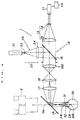
- Fig. 1 is a drawing showing the optical arrangement of a first embodiment of the lens capsule laser cutting apparatus of this invention.
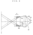
- Fig. 2 is a partial optical drawing of a second embodiment of the lens capsule laser cutting apparatus of this invention.
- Fig. 3 is a partial optical drawing of a third embodiment of the lens capsule laser cutting apparatus of this invention.
- Fig. 4 is a drawing showing the optical arrangement of a modification of the first embodiment.
- Figs 5A and 5B are schematic drawings showing the way in which an IOL is inserted into the posterior chamber.
- projecting means 1 of the lens capsule laser cutting apparatus of this invention comprises an optical system 10 for projecting a laser beam and an aiming optical system 20.
- the projecting optical system 10 comprises a laser source 11 generating a laser beam capable of ablating the tissue of living organisms or a lens capsule.
- Lasers which satisfy this condition include for example Nd:YAG and Dye.
- the wavelengths of these laser beam lie in the approximate range 0.4 ⁇ m - 1.5 ⁇ m which is not absorbed by water, the principal constituent of the cornea and aqueous humor, and a wavelength of approximate 1.06 ⁇ m is preferable.
- the laser source is therefore an Nd:YAG laser.
- it is desirable that the laser power density on the lens capsule is at least 108W/cm2 in order that the capsule is not evaporated by absorbing laser energy, but is destroyed by the laser's optical breakdown effect.
- the Nd:YAG laser 11 is connected to a radiation control switch 11a. When this switch is turned on, the laser source generates an infrared pulse laser beam.
- the output laser beam from the Nd:YAG laser source 11 is enlarged in radius through a beam expander 13 which comprises a concave lens 14 and a convex lens 15.
- the laser beam from the convex lens 15 is made parallel, and is projected in turn toward a diverging prismatic lens (axicon lens) 18 through a condensing (focusing) lens 17 and a cold mirror 16.
- the axicon lens 18 has a prism-like reverse conical shape in sectional view, and the outer edge thereof (prism base) is larger in width than the optical axis portion thereof. Due to the prism function of the axicon lens 18, the output beam therefrom is made ring-like. The ring-like beam is then reflected by a dichroic mirror 19, and converged on the anterior lens capsule FR of a crystallin lens CR to be treated through the cornea 31 of a patient's eye 30.
- the anterior lens capsule FR is cut out in a ring shape by the energy of the laser beam, and a circular hole HL (Figs. 5A, 5B) is obtained in the anterior lens capsule FR.
- the beam expander 13 contributes to enlarging the numerical aperture of lens 17 by increasing the radius of the ring-like incident laser beam.
- the axicon lens 18 is preferably mounted so that it is movable along the optical axis O1 in the direction of the arrow A.
- the aiming optical system 20 (see Fig. 1) comprises a He-Ne laser source 21, a beam expander 22 and the cold mirror 16.
- the He-Ne laser source 21 generates a visible laser beam.
- the beam expander 22 comprises a concave lens 23 and a convex lens 24.
- the cold mirror 16 reflects only incident He-Ne laser beams, while Nd:YAG laser beams pass therethrough.
- the Ne-He laser beam from the laser source 21 is enlarged in diameter by the expander 22 from which the output laser beam is in turn reflected by the cold mirror 16 and projected to the condensing (focusing) lens 17.
- the He-Ne laser beam from the condensing lens 17 therefore travels along the same optical path as the Nd:YAG laser beam.
- this laser cutting apparatus is provided with an operation microscope 2 as indicated by the phantom lines in Fig. 1.
- This operation microscope 2 is well known in the ophthalmology field, and its detailed explanation is therefore omitted.
- the optical axis O2 of the operation microscope 2 is adjusted to be coincident with that of the laser cutting apparatus O1.
- the dichroic mirror 19 functions as a half mirror for the He-Ne laser beam, but as a full reflecting mirror for the Nd:YAG laser beam. A surgeon can thus determine the optimum diameter of the hole HL to be created in the anterior lens capsule FR of lens CR by observing the He-Ne laser beam projected thereon through the operation microscope 2.
- An annular incision can be made in the anterior lens capsule FR using this laser cutting apparatus as described below.
- Visible aiming laser beam from the He-Ne laser source 21 is projected on the anterior lens capsule FR of a patient's eye through the beam expander 22, cold mirror 16, focusing lens 17, (condensing lens 17), axicon lens 18 and dichroic mirror 19.
- the visible aiming laser beam projected on the anterior lens capsule FR is ring-like in shape, and it can be observed through the operation microscope 2.
- the focus of the projected laser beam may be adjusted by moving the operation microscope and laser cutting apparatus along the optical axis O2 together with each other.
- the axicon lens 18 is moved along the optical axis O1 so that the diameter of the ring-like laser beam 32 is optimum.
- the control switch 11a is turned on and the Nd:YAG laser source 11 generates an invisible Nd:YAG pulse laser beam.
- the Nd:YAG laser beam which is to make an incision on the anterior lens capsule FR of lens CR is then projected by the beam expander 13, cold mirror 16, condensing lens 17, axicon lens 18 and dichroic mirror 19.
- Figs. 2 and 3 respectively show second and third embodiments of the lens capsule laser cutting apparatus of this invention.
- the optical system of the second embodiment comprises a fixed beam expander 51, focusing lens 17 and axicon mirror 60 which can be moved along the optical axis thereof.
- the fixed beam expander 51 is directly connected optically to a laser beam source 11 not shown.
- the beam expander 51 performs a similar function to the beam expander 13 shown in Fig. 1. It is moreover preferable that the cold mirror 16 is disposed between the laser source 11 and fixed beam expander 51.
- the cold mirror 16 may be interposed between the fixed beam expander 51 and focusing lens 17.
- the fixed beam expander 51 comprises a diverging axicon lens 53 and a converging axicon lens 52.
- the movable axicon mirror 60 has an inner mirror surface 61. In response to its movement along the optical axis in the direction of arrow A, the diameter of the annular incision varies.
- the third embodiment shown in Fig. 3 has an outer mirror surface 71 on a movable axicon mirror 70 which can be adjusted in an axial direction thereof.
- the axicon mirror 70 is positioned in place of the axicon lens 18 shown in Fig. 1, and performs substantially the same function as the latter.
- Fig. 4 shows a further modification of the first embodiment (Fig. 1).
- a converging (focusing) lens 17 may also be disposed between the axicon lens 18 (which is of the converging type in this embodiment) and the dichroic mirror 19.
- the relay lens 100 makes an intermediate image 101 of the laser beam from the beam expander 13 at its focal point situated before the axicon lens 18.
- the focusing lens 17 situated after the axicon lens 18 converges the laser beam from the axicon lens onto the lens capsule.
- a Nd:YAG laser is respectively used, but a visible pulse laser such as a Dye laser may also be used as another optical source.
Landscapes
- Health & Medical Sciences (AREA)
- Ophthalmology & Optometry (AREA)
- Heart & Thoracic Surgery (AREA)
- Vascular Medicine (AREA)
- Optics & Photonics (AREA)
- Surgery (AREA)
- Engineering & Computer Science (AREA)
- Biomedical Technology (AREA)
- Physics & Mathematics (AREA)
- Nuclear Medicine, Radiotherapy & Molecular Imaging (AREA)
- Life Sciences & Earth Sciences (AREA)
- Animal Behavior & Ethology (AREA)
- General Health & Medical Sciences (AREA)
- Public Health (AREA)
- Veterinary Medicine (AREA)
- Laser Surgery Devices (AREA)
Description
- This invention concerns an apparatus for performing ophthalmic surgery, and in particular, a lens capsule laser cutting apparatus suitable for removing the anterior lens capsule in extracapsular cataracy extractions.
- Cataracts are a disease where the lens nucleus becomes cloudy whitish grey, and visual power declines as a result. Cataract surgery involves removal of the nucleus.
- Cataract surgeries are presently performed by means of the following 3 techniques.
- (1) Intracapsular cataract extraction
- (2) Extracapsular cataract extraction (wherein an incision is made in the anterior lens capsule by a special scalpel formed by transforming a hypodermic needle, the anterior lens capsule is exposed to ultrasonic waves, and the lens nucleus is aspirated after emulsification), and
- (3) Ultrasonic cataract operations (wherein both the anterior lens capsule and lens nucleus are aspirated after emulsification by ultrasonic waves).
- In (1), the crystallin is extracted together with the capsule. In (2) and (3), the posterior lens capsule BR is left as shown in Fig. 5A and 5B, and only part of the anterior lens capsule FR, lens capsule and lens are removed.
- Recently, it has become frequent to insert an intraocular lens (IOL) after removing the lens nucleus by method (1), (2) or (3). It is desirable to insert the IOL in the posterior chamber, and also preferable from the safety viewpoint to fix it in the capsule after insertion (Fig. 5A). Methods (2) and (3) are becoming increasingly common as they are better adapted to this posterior chamber lens.
- The recent consensus of academic opinion is that method (2) is far superior to method (3) (and that method (3) is far more dangerous). There is one way of performing (2) known as Continuous Circular Capsulorhexis (C.C.C.) wherein an annular incision is made in the anterior lens capsule. This is now the most usual technique for the following reasons:
- (1) The incision on the anterior lens capsule is symmetrical,
- (2) The rim of the anterior lens capsule does not tear after IOL insertion,
- (3) There is little damage to ocular tissues after IOL insertion,
- (4) As the IOL is stable, preferable visual acuity is maintained.
- The success or failure of the C.C.C. technique however depends on (1) how close the incision in the anterior lens capsule is to a perfect circle (2) how clean the incision is, and (3) whether the incision can be made without damaging other ocular tissues. These factors depend largely on the experience and skill of the surgion. If the incision is made without satisfying conditions (1) - (3), the zonules of Zinn and lens capsules would be damaged, and it would also have an adverse effect on the set of procedures carried out subsequent to the incision such as extraction of the lens nucleus (phacoemulsification and aspiration), aspiration of the cortex, and insertion of the intraocular lens. The above conditions are therefore crucial to the success of the operation in the early or late post-operative results.
- If the operator is not sufficiently experienced, the capsule may tear when the incision in the anterior lens capsule is made. Further, if the anterior lens capsule incision is asymmetrical (not circular), or if the incision is circular but has a zig-zag edge, uneven stresses are set up in the following steps, i.e. extraction of the lens nucleus (phacoemulsification and aspiration), aspiration of the cortex and insertion of the intraocular lens (IOL). The lens capsule may therefore tear, and the zonules of Zinn may be damaged. Further, if the anterior lens capsule incision is asymmetrical, the inserted IOL is sometimes found not to coincide with the ocular optical axis after the surgery.
- This invention therefore aims to provide a lens capsule laser cutting apparatus which improves the post-operative result of cataract surgery, and permits the C.C.C. technique to be performed accurately and easily without the slightest damage to other ocular tissues.
- FR-A-2 458 272 discloses a lens capsule cutting apparatus according to the preamble of
claim 1. - In order to achieve the above objectives, the lens capsule cutting apparatus of this invention is in accordance with
claim 1. - Said converging means preferably consists of one focusing lens. Further, it is desirable that said axicon means comprises at least one axicon lens capable of moving along the optical path of said projecting means.
- Said projecting means should preferably comprise an expander means to expand the radius of the laser beam generated by said generating means.
- The source is preferably an infrared pulse laser with a wavelength of approximate 1.06 µm, but a Dye laser may also be used.
- The apparatus also includes an aiming means for projecting a visible ring-like laser beam on the lens capsule which are substantially coincident with the laser beam projected by said axicon means.
- The optical path of said aiming means preferably overlaps with a part of the optical path of said projecting means. Preferably, the aiming means comprises a visible laser beam source, and a mirror obliquely interposed between said beam expander means and said converging means for reflecting the visible laser beam and allowing the laser beam from the generating means to pass therethrough.
- By means of the lens capsule laser cutting apparatus of this invention, a lens capsule can be cut out in a perfect circle with a ring-like laser beam. As the laser cutting apparatus involves no contact with ocular tissues, moreover, the incision can be made without applying great effort, and there can be little damage to the zonules of Zinn or other ocular tissues.
- Using this apparatus, the annular incision on the lens capsule can be made uniform and continuous.
- Uneven stresses on the incision are therefore reduced in subsequent operative procedures such as phacoemalsificate aspiration of the lens nucleus, aspiration of the lens cortex and insertion of the IOL, and there is less risk of tearing the lens capsule and thereby damaging the zonules of Zinn. This leads to better results in the early and later post-operative results.
- Further, as the incision in the anterior lens capsule can be clean, the IOL inserted in the capsule can be maintained exactly at the ocular optical axis after the surgery.
- Further, no special training is required to perform the incision, and the operation can be carried out in less time. Moreover, by focusing the laser beam on the posterior lens capsule, it is also possible to perform after-cataract surgery.
- Fig. 1 is a drawing showing the optical arrangement of a first embodiment of the lens capsule laser cutting apparatus of this invention.
- Fig. 2 is a partial optical drawing of a second embodiment of the lens capsule laser cutting apparatus of this invention.
- Fig. 3 is a partial optical drawing of a third embodiment of the lens capsule laser cutting apparatus of this invention.
- Fig. 4 is a drawing showing the optical arrangement of a modification of the first embodiment.
- Figs 5A and 5B are schematic drawings showing the way in which an IOL is inserted into the posterior chamber.
- The preferred embodiments of this invention shall be described in more detail with reference to the examples shown in the attached drawings.
- As shown in Fig. 1, projecting means 1 of the lens capsule laser cutting apparatus of this invention comprises an
optical system 10 for projecting a laser beam and an aimingoptical system 20. - The projecting
optical system 10 comprises a laser source 11 generating a laser beam capable of ablating the tissue of living organisms or a lens capsule. Lasers which satisfy this condition include for example Nd:YAG and Dye. The wavelengths of these laser beam lie in the approximate range 0.4 µm - 1.5 µm which is not absorbed by water, the principal constituent of the cornea and aqueous humor, and a wavelength of approximate 1.06 µm is preferable. The laser source is therefore an Nd:YAG laser. Further, it is desirable that the laser power density on the lens capsule is at least 10⁸W/cm² in order that the capsule is not evaporated by absorbing laser energy, but is destroyed by the laser's optical breakdown effect. - The Nd:YAG laser 11 is connected to a radiation control switch 11a. When this switch is turned on, the laser source generates an infrared pulse laser beam.
- The output laser beam from the Nd:YAG laser source 11 is enlarged in radius through a
beam expander 13 which comprises aconcave lens 14 and aconvex lens 15. The laser beam from theconvex lens 15 is made parallel, and is projected in turn toward a diverging prismatic lens (axicon lens) 18 through a condensing (focusing)lens 17 and acold mirror 16. Theaxicon lens 18 has a prism-like reverse conical shape in sectional view, and the outer edge thereof (prism base) is larger in width than the optical axis portion thereof. Due to the prism function of theaxicon lens 18, the output beam therefrom is made ring-like. The ring-like beam is then reflected by adichroic mirror 19, and converged on the anterior lens capsule FR of a crystallin lens CR to be treated through thecornea 31 of a patient'seye 30. - As a result, the anterior lens capsule FR is cut out in a ring shape by the energy of the laser beam, and a circular hole HL (Figs. 5A, 5B) is obtained in the anterior lens capsule FR.
- To induce an optical breakdown in the anterior lens capsule FR, it is required to set the width of the ring-like laser beam to be narrow. and the numerical aperture of the focusing
lens 17 must therefore be large. Thebeam expander 13 contributes to enlarging the numerical aperture oflens 17 by increasing the radius of the ring-like incident laser beam. - In order to obtain a hole HL of desired diameter in the anterior lens capsule FR (normally 6 - 6.5 mm), it is necessary to vary the diameter of the ring-
like laser beam 32 projected on the anterior lens capsule FR. For thin purpose, theaxicon lens 18 is preferably mounted so that it is movable along the optical axis O₁ in the direction of the arrow A. - The aiming optical system 20 (see Fig. 1) comprises a He-
Ne laser source 21, abeam expander 22 and thecold mirror 16. The He-Ne laser source 21 generates a visible laser beam. Thebeam expander 22 comprises aconcave lens 23 and aconvex lens 24. Thecold mirror 16 reflects only incident He-Ne laser beams, while Nd:YAG laser beams pass therethrough. - The Ne-He laser beam from the
laser source 21 is enlarged in diameter by theexpander 22 from which the output laser beam is in turn reflected by thecold mirror 16 and projected to the condensing (focusing)lens 17. The He-Ne laser beam from the condensinglens 17 therefore travels along the same optical path as the Nd:YAG laser beam. - To observe the anterior lens capsule FR of the lens CR and the ring-like He-Ne laser beam projected thereon, this laser cutting apparatus is provided with an
operation microscope 2 as indicated by the phantom lines in Fig. 1. Thisoperation microscope 2 is well known in the ophthalmology field, and its detailed explanation is therefore omitted. - The optical axis O₂ of the
operation microscope 2 is adjusted to be coincident with that of the laser cutting apparatus O₁. Thedichroic mirror 19 functions as a half mirror for the He-Ne laser beam, but as a full reflecting mirror for the Nd:YAG laser beam. A surgeon can thus determine the optimum diameter of the hole HL to be created in the anterior lens capsule FR of lens CR by observing the He-Ne laser beam projected thereon through theoperation microscope 2. - An annular incision can be made in the anterior lens capsule FR using this laser cutting apparatus as described below.
- Visible aiming laser beam from the He-
Ne laser source 21 is projected on the anterior lens capsule FR of a patient's eye through thebeam expander 22,cold mirror 16, focusinglens 17, (condensing lens 17),axicon lens 18 anddichroic mirror 19. - The visible aiming laser beam projected on the anterior lens capsule FR is ring-like in shape, and it can be observed through the
operation microscope 2. The focus of the projected laser beam may be adjusted by moving the operation microscope and laser cutting apparatus along the optical axis O₂ together with each other. - Next, the
axicon lens 18 is moved along the optical axis O₁ so that the diameter of the ring-like laser beam 32 is optimum. After the diameter of the ring-like laser beam 32 has been set to optimum by means of theoperation microscope 2 and aimingsystem 20, the control switch 11a is turned on and the Nd:YAG laser source 11 generates an invisible Nd:YAG pulse laser beam. The Nd:YAG laser beam which is to make an incision on the anterior lens capsule FR of lens CR is then projected by thebeam expander 13,cold mirror 16, condensinglens 17,axicon lens 18 anddichroic mirror 19. - Figs. 2 and 3 respectively show second and third embodiments of the lens capsule laser cutting apparatus of this invention.
- The optical system of the second embodiment comprises a fixed
beam expander 51, focusinglens 17 andaxicon mirror 60 which can be moved along the optical axis thereof. In this embodiment, the fixedbeam expander 51 is directly connected optically to a laser beam source 11 not shown. Thebeam expander 51 performs a similar function to thebeam expander 13 shown in Fig. 1. It is moreover preferable that thecold mirror 16 is disposed between the laser source 11 and fixedbeam expander 51. - Alternatively, the
cold mirror 16 may be interposed between the fixedbeam expander 51 and focusinglens 17. The fixedbeam expander 51 comprises a divergingaxicon lens 53 and a convergingaxicon lens 52. Themovable axicon mirror 60 has aninner mirror surface 61. In response to its movement along the optical axis in the direction of arrow A, the diameter of the annular incision varies. - The third embodiment shown in Fig. 3 has an
outer mirror surface 71 on amovable axicon mirror 70 which can be adjusted in an axial direction thereof. Theaxicon mirror 70 is positioned in place of theaxicon lens 18 shown in Fig. 1, and performs substantially the same function as the latter. - Fig. 4 shows a further modification of the first embodiment (Fig. 1). If a
relay lens 100 is added, a converging (focusing)lens 17 may also be disposed between the axicon lens 18 (which is of the converging type in this embodiment) and thedichroic mirror 19. Therelay lens 100 makes an intermediate image 101 of the laser beam from thebeam expander 13 at its focal point situated before theaxicon lens 18. The focusinglens 17 situated after theaxicon lens 18 converges the laser beam from the axicon lens onto the lens capsule. - In these embodiments a Nd:YAG laser is respectively used, but a visible pulse laser such as a Dye laser may also be used as another optical source.
- The present embodiment is to be considered in all respects as illustrative and not restrictive, the scope of the invention being indicated by the appended claims rather than by the foregoing description, and all changes which come within the meaning of the claims are therefore intended to be embraced therein.
Claims (11)
- A lens capsule cutting apparatus comprising :
means for generating an infrared pulse laser beam having a wavelength of 0.4 µm to 1.5 µm ; and
means for projecting the laser beam onto a lens capsule for cutting said capsule ;
said projecting means incluing a converging optical means to converge the laser beam, characterized in that said projecting means also includes an axicon lens means for projecting the converged beam in an annular shape onto said capsule and varying the diameter of the beam ;
the converged laser beam on said lens capsule having a power density of no less than 10⁸ W/cm². - A lens capsule cutting apparatus as defined in Claim 1 wherein said axicon means can be moved along an optical axis of said projecting means.
- A lens capsule cutting apparatus as defined in claim 2 wherein said projecting means further comprises a beam expander to enlarge an energing radius of the laser beam emerging from said generating means, wherein said converging optical means converges the laser beam from said beam expander through said axicon lens means onto said lens capsule.
- A lens capsule cutting apparatus as defined in claim 2 wherein said projecting means further comprises a beam expander to enlarge a beam radius of the laser beam and an image forming optical means to form an intermediate image of said laser beam from said beam expander at an intermediate point situated before said axicon lens means, wherein said converging optical means is situated after said axicon lens means for converging said laser beam from said axicon lens means onto said lens capsule.
- A lens capsule cutting apparatus as defined in Claim 1 wherein the wavelength of the beam generated by said infrared pulse beam generator is 1.06 µm.
- A lens capsule cutting apparatus as defined in claim 3 further comprising an aiming means for projecting a visible annularly shaped laser beam coincident with the laser beam projected by said axicon lens means on the lens capsule, in order to see a visible laser beam spot thereon.
- A lens capsule cutting apparatus as defined in claim 6 wherein an optical axis of said aiming means overlaps with part of the optical axis of said projecting means.
- A lens capsule cutting apparatus as defined in claim 7 wherein said aiming means comprises a visible laser beam source and a mirror which reflects the visible laser beam while allowing the laser beam from said generating means to pass therethough, said mirror being positioned obliquely between said beam expander means and said converging optical means.
- A lens capsule cutting aparatus as defined in claim 5 wherein said generating means is a Nd:YAG laser optical source.
- A lens capsule cutting apparatus as defined in claim 1 wherein said generating means is a Dye laser optical source.
- A lens capsule cutting apparatus according to claim 3 wherein said beam expander comprises a variable diverging beam expander.
Applications Claiming Priority (2)
| Application Number | Priority Date | Filing Date | Title |
|---|---|---|---|
| JP191446/90 | 1990-07-19 | ||
| JP2191446A JPH0475654A (en) | 1990-07-19 | 1990-07-19 | Capsular laser incision device |
Publications (2)
| Publication Number | Publication Date |
|---|---|
| EP0467775A1 EP0467775A1 (en) | 1992-01-22 |
| EP0467775B1 true EP0467775B1 (en) | 1996-04-10 |
Family
ID=16274761
Family Applications (1)
| Application Number | Title | Priority Date | Filing Date |
|---|---|---|---|
| EP19910401985 Expired - Lifetime EP0467775B1 (en) | 1990-07-19 | 1991-07-16 | Lens capsule laser cutting apparatus |
Country Status (4)
| Country | Link |
|---|---|
| EP (1) | EP0467775B1 (en) |
| JP (1) | JPH0475654A (en) |
| DE (1) | DE69118600T2 (en) |
| ES (1) | ES2088787T3 (en) |
Cited By (2)
| Publication number | Priority date | Publication date | Assignee | Title |
|---|---|---|---|---|
| DE102014004027A1 (en) | 2014-03-21 | 2015-09-24 | Carl Zeiss Meditec Ag | Laser device for processing a tissue in the anterior section of an eye |
| DE102014004026A1 (en) | 2014-03-21 | 2015-09-24 | Carl Zeiss Meditec Ag | Ophthalmic device for processing a tissue in the foreground of an eye |
Families Citing this family (12)
| Publication number | Priority date | Publication date | Assignee | Title |
|---|---|---|---|---|
| WO1993014817A2 (en) * | 1992-01-15 | 1993-08-05 | Premier Laser Systems, Inc. | Corneal sculpting using laser energy |
| US5613965A (en) * | 1994-12-08 | 1997-03-25 | Summit Technology Inc. | Corneal reprofiling using an annular beam of ablative radiation |
| US6063072A (en) * | 1994-12-08 | 2000-05-16 | Summit Technology, Inc. | Methods and systems for correction of hyperopia and/or astigmatism using ablative radiation |
| RU2130762C1 (en) * | 1997-12-10 | 1999-05-27 | Федоров Святослав Николаевич | Device for performing ophthalmosurgical operations |
| US6149643A (en) * | 1998-09-04 | 2000-11-21 | Sunrise Technologies International, Inc. | Method and apparatus for exposing a human eye to a controlled pattern of radiation |
| AU772600B2 (en) * | 1999-10-21 | 2004-05-06 | Nidek Co., Ltd. | Amount-of-cornea-to-be-excised determining device and cornea surgery device |
| CA2554165A1 (en) * | 2004-01-22 | 2005-08-11 | Solx, Inc. | Glaucoma treatment method |
| US7252662B2 (en) * | 2004-11-02 | 2007-08-07 | Lenticular Research Group Llc | Apparatus and processes for preventing or delaying one or more symptoms of presbyopia |
| US8394084B2 (en) | 2005-01-10 | 2013-03-12 | Optimedica Corporation | Apparatus for patterned plasma-mediated laser trephination of the lens capsule and three dimensional phaco-segmentation |
| DE102007035850A1 (en) * | 2007-07-31 | 2009-02-05 | Carl Zeiss Meditec Ag | laser system |
| EP2240108B1 (en) * | 2008-01-09 | 2015-04-29 | Alcon LenSx, Inc. | Photodisruptive laser fragmentation of tissue |
| EP4415666A1 (en) * | 2021-10-14 | 2024-08-21 | Appasamy Associates Pvt Ltd | Single and/or dual (532 and/or 577) nm laser delivery system attached to an ophthalmic microscope |
Family Cites Families (6)
| Publication number | Priority date | Publication date | Assignee | Title |
|---|---|---|---|---|
| US3348547A (en) * | 1964-10-16 | 1967-10-24 | American Optical Corp | Photocoagulating apparatus |
| US3971382A (en) * | 1973-12-11 | 1976-07-27 | Krasnov Mikhail M | Method of non-surgical treatment of cataracts |
| FR2458272A2 (en) * | 1979-06-08 | 1981-01-02 | Rosa Daniele | Laser for ophthalmic surgery - comprises pulsed YAG system providing 400 pico second bursts of very high intensity radiation |
| IL78416A0 (en) * | 1986-04-03 | 1986-08-31 | Uzi Sharon | Laser surgery system |
| US4887592A (en) * | 1987-06-02 | 1989-12-19 | Hanspeter Loertscher | Cornea laser-cutting apparatus |
| US5152759A (en) * | 1989-06-07 | 1992-10-06 | University Of Miami, School Of Medicine, Dept. Of Ophthalmology | Noncontact laser microsurgical apparatus |
-
1990
- 1990-07-19 JP JP2191446A patent/JPH0475654A/en active Pending
-
1991
- 1991-07-16 DE DE1991618600 patent/DE69118600T2/en not_active Expired - Fee Related
- 1991-07-16 ES ES91401985T patent/ES2088787T3/en not_active Expired - Lifetime
- 1991-07-16 EP EP19910401985 patent/EP0467775B1/en not_active Expired - Lifetime
Cited By (2)
| Publication number | Priority date | Publication date | Assignee | Title |
|---|---|---|---|---|
| DE102014004027A1 (en) | 2014-03-21 | 2015-09-24 | Carl Zeiss Meditec Ag | Laser device for processing a tissue in the anterior section of an eye |
| DE102014004026A1 (en) | 2014-03-21 | 2015-09-24 | Carl Zeiss Meditec Ag | Ophthalmic device for processing a tissue in the foreground of an eye |
Also Published As
| Publication number | Publication date |
|---|---|
| DE69118600D1 (en) | 1996-05-15 |
| JPH0475654A (en) | 1992-03-10 |
| DE69118600T2 (en) | 1996-12-12 |
| EP0467775A1 (en) | 1992-01-22 |
| ES2088787T3 (en) | 1996-09-16 |
Similar Documents
| Publication | Publication Date | Title |
|---|---|---|
| US20250248851A1 (en) | Arrangement for the oct-based laser vitreolysis | |
| US6325792B1 (en) | Ophthalmic surgical laser and method | |
| JP2582857B2 (en) | Ophthalmic laser surgery device | |
| CA2266044C (en) | Method for corneal laser surgery | |
| US8292877B2 (en) | System and method for incising material | |
| EP0484005B1 (en) | Laser thermokeratoplasty apparatus | |
| US5290272A (en) | Method for the joining of ocular tissues using laser light | |
| US8425497B2 (en) | Method and apparatus for patterned plasma-mediated laser trephination of the lens capsule and three dimensional phaco-segmentation | |
| EP0467775B1 (en) | Lens capsule laser cutting apparatus | |
| US20140350533A1 (en) | Contactless photodisruptive laser cataract surgery | |
| US6805694B2 (en) | Laser system for corneal grafting | |
| WO1994009849A1 (en) | Method of performing ophthalmic surgery | |
| AU8089298A (en) | Intrastromal photorefractive keratectomy | |
| JP2004329881A (en) | Method and apparatus for cornea intraparenchymal refraction correction surgery | |
| CA2127029C (en) | Intrastromal photorefractive keratectomy | |
| US20090299345A1 (en) | System and method for reshaping a cornea using a combination of liob and structural change procedures | |
| US10206817B2 (en) | Laser assisted cataract surgery | |
| US20240335324A1 (en) | SINGLE AND/OR DUAL (532 AND/OR 577) nm LASER DELIVERY SYSTEM ATTACHED TO AN OPHTHALMIC MICROSCOPE | |
| US9820886B2 (en) | Laser assisted cataract surgery | |
| US10231872B2 (en) | Laser assisted cataract surgery | |
| JP2024520749A (en) | Method and system for forming an intracorneal incision using a convex contact surface - Patents.com | |
| NAGY et al. | History of Femtosecond Laser-Assisted Cataract Surgery | |
| EP1941849A2 (en) | Method for corneal laser surgery | |
| US20150245945A1 (en) | Laser assisted cataract surgery |
Legal Events
| Date | Code | Title | Description |
|---|---|---|---|
| PUAI | Public reference made under article 153(3) epc to a published international application that has entered the european phase |
Free format text: ORIGINAL CODE: 0009012 |
|
| AK | Designated contracting states |
Kind code of ref document: A1 Designated state(s): DE ES FR GB IT |
|
| 17P | Request for examination filed |
Effective date: 19920625 |
|
| 17Q | First examination report despatched |
Effective date: 19931108 |
|
| GRAH | Despatch of communication of intention to grant a patent |
Free format text: ORIGINAL CODE: EPIDOS IGRA |
|
| GRAA | (expected) grant |
Free format text: ORIGINAL CODE: 0009210 |
|
| ITF | It: translation for a ep patent filed | ||
| AK | Designated contracting states |
Kind code of ref document: B1 Designated state(s): DE ES FR GB IT |
|
| REF | Corresponds to: |
Ref document number: 69118600 Country of ref document: DE Date of ref document: 19960515 |
|
| REG | Reference to a national code |
Ref country code: ES Ref legal event code: BA2A Ref document number: 2088787 Country of ref document: ES Kind code of ref document: T3 |
|
| ET | Fr: translation filed | ||
| REG | Reference to a national code |
Ref country code: ES Ref legal event code: FG2A Ref document number: 2088787 Country of ref document: ES Kind code of ref document: T3 |
|
| PLBE | No opposition filed within time limit |
Free format text: ORIGINAL CODE: 0009261 |
|
| STAA | Information on the status of an ep patent application or granted ep patent |
Free format text: STATUS: NO OPPOSITION FILED WITHIN TIME LIMIT |
|
| 26N | No opposition filed | ||
| REG | Reference to a national code |
Ref country code: GB Ref legal event code: IF02 |
|
| PGFP | Annual fee paid to national office [announced via postgrant information from national office to epo] |
Ref country code: ES Payment date: 20050620 Year of fee payment: 15 |
|
| PGFP | Annual fee paid to national office [announced via postgrant information from national office to epo] |
Ref country code: GB Payment date: 20060712 Year of fee payment: 16 |
|
| PGFP | Annual fee paid to national office [announced via postgrant information from national office to epo] |
Ref country code: DE Payment date: 20060713 Year of fee payment: 16 |
|
| PGFP | Annual fee paid to national office [announced via postgrant information from national office to epo] |
Ref country code: FR Payment date: 20060719 Year of fee payment: 16 |
|
| PGFP | Annual fee paid to national office [announced via postgrant information from national office to epo] |
Ref country code: IT Payment date: 20060731 Year of fee payment: 16 |
|
| GBPC | Gb: european patent ceased through non-payment of renewal fee |
Effective date: 20070716 |
|
| PG25 | Lapsed in a contracting state [announced via postgrant information from national office to epo] |
Ref country code: DE Free format text: LAPSE BECAUSE OF NON-PAYMENT OF DUE FEES Effective date: 20080201 |
|
| PG25 | Lapsed in a contracting state [announced via postgrant information from national office to epo] |
Ref country code: GB Free format text: LAPSE BECAUSE OF NON-PAYMENT OF DUE FEES Effective date: 20070716 |
|
| REG | Reference to a national code |
Ref country code: FR Ref legal event code: ST Effective date: 20080331 |
|
| PG25 | Lapsed in a contracting state [announced via postgrant information from national office to epo] |
Ref country code: FR Free format text: LAPSE BECAUSE OF NON-PAYMENT OF DUE FEES Effective date: 20070731 |
|
| REG | Reference to a national code |
Ref country code: ES Ref legal event code: FD2A Effective date: 20070717 |
|
| PG25 | Lapsed in a contracting state [announced via postgrant information from national office to epo] |
Ref country code: ES Free format text: LAPSE BECAUSE OF NON-PAYMENT OF DUE FEES Effective date: 20070717 |
|
| PG25 | Lapsed in a contracting state [announced via postgrant information from national office to epo] |
Ref country code: IT Free format text: LAPSE BECAUSE OF NON-PAYMENT OF DUE FEES Effective date: 20070716 |