EP0467771B1 - Dispositif d'attache d'un frein à bande - Google Patents
Dispositif d'attache d'un frein à bande Download PDFInfo
- Publication number
- EP0467771B1 EP0467771B1 EP19910401975 EP91401975A EP0467771B1 EP 0467771 B1 EP0467771 B1 EP 0467771B1 EP 19910401975 EP19910401975 EP 19910401975 EP 91401975 A EP91401975 A EP 91401975A EP 0467771 B1 EP0467771 B1 EP 0467771B1
- Authority
- EP
- European Patent Office
- Prior art keywords
- brake
- band
- fastening device
- rod
- feedback
- Prior art date
- Legal status (The legal status is an assumption and is not a legal conclusion. Google has not performed a legal analysis and makes no representation as to the accuracy of the status listed.)
- Expired - Lifetime
Links
- 238000006243 chemical reaction Methods 0.000 description 15
- 241001417494 Sciaenidae Species 0.000 description 4
- 238000006073 displacement reaction Methods 0.000 description 3
Images
Classifications
-
- F—MECHANICAL ENGINEERING; LIGHTING; HEATING; WEAPONS; BLASTING
- F16—ENGINEERING ELEMENTS AND UNITS; GENERAL MEASURES FOR PRODUCING AND MAINTAINING EFFECTIVE FUNCTIONING OF MACHINES OR INSTALLATIONS; THERMAL INSULATION IN GENERAL
- F16H—GEARING
- F16H63/00—Control outputs from the control unit to change-speed- or reversing-gearings for conveying rotary motion or to other devices than the final output mechanism
- F16H63/02—Final output mechanisms therefor; Actuating means for the final output mechanisms
- F16H63/30—Constructional features of the final output mechanisms
- F16H63/3003—Band brake actuating mechanisms
-
- B—PERFORMING OPERATIONS; TRANSPORTING
- B23—MACHINE TOOLS; METAL-WORKING NOT OTHERWISE PROVIDED FOR
- B23P—METAL-WORKING NOT OTHERWISE PROVIDED FOR; COMBINED OPERATIONS; UNIVERSAL MACHINE TOOLS
- B23P15/00—Making specific metal objects by operations not covered by a single other subclass or a group in this subclass
- B23P15/18—Making specific metal objects by operations not covered by a single other subclass or a group in this subclass brake shoes
-
- F—MECHANICAL ENGINEERING; LIGHTING; HEATING; WEAPONS; BLASTING
- F16—ENGINEERING ELEMENTS AND UNITS; GENERAL MEASURES FOR PRODUCING AND MAINTAINING EFFECTIVE FUNCTIONING OF MACHINES OR INSTALLATIONS; THERMAL INSULATION IN GENERAL
- F16D—COUPLINGS FOR TRANSMITTING ROTATION; CLUTCHES; BRAKES
- F16D49/00—Brakes with a braking member co-operating with the periphery of a drum, wheel-rim, or the like
- F16D49/08—Brakes with a braking member co-operating with the periphery of a drum, wheel-rim, or the like shaped as an encircling band extending over approximately 360 degrees
-
- F—MECHANICAL ENGINEERING; LIGHTING; HEATING; WEAPONS; BLASTING
- F16—ENGINEERING ELEMENTS AND UNITS; GENERAL MEASURES FOR PRODUCING AND MAINTAINING EFFECTIVE FUNCTIONING OF MACHINES OR INSTALLATIONS; THERMAL INSULATION IN GENERAL
- F16D—COUPLINGS FOR TRANSMITTING ROTATION; CLUTCHES; BRAKES
- F16D65/00—Parts or details
- F16D65/02—Braking members; Mounting thereof
- F16D65/04—Bands, shoes or pads; Pivots or supporting members therefor
-
- F—MECHANICAL ENGINEERING; LIGHTING; HEATING; WEAPONS; BLASTING
- F16—ENGINEERING ELEMENTS AND UNITS; GENERAL MEASURES FOR PRODUCING AND MAINTAINING EFFECTIVE FUNCTIONING OF MACHINES OR INSTALLATIONS; THERMAL INSULATION IN GENERAL
- F16D—COUPLINGS FOR TRANSMITTING ROTATION; CLUTCHES; BRAKES
- F16D65/00—Parts or details
- F16D65/02—Braking members; Mounting thereof
- F16D65/04—Bands, shoes or pads; Pivots or supporting members therefor
- F16D65/06—Bands, shoes or pads; Pivots or supporting members therefor for externally-engaging brakes
- F16D65/065—Brake bands
- F16D65/067—Brake bands with means for mounting, e.g. end connection members
Definitions
- the present invention relates to a device for attaching a band brake, which is more particularly mounted on an automatic gearbox of a passenger motor vehicle.
- Band brake attachment devices which use two holding pins force fitted into the casing supporting the entire band brake device. These two pins cooperate with notches arranged on said band brake.
- the aim of the present invention is to propose a device for attaching a band brake, in particular for an automatic gearbox, which is arranged so as to adapt to the different positions of the end of said band brake, in order to obtain support without relative displacement of one relative to the other.
- the band brake attachment device thus has the advantage of offering an automatic backlash system, and which adapts to the different positions of the end of the brake, in order to obtain a support having no relative displacement, l one over the other.
- FIG. 1 The device for attaching a band brake 1 according to the invention is shown in FIG. 1.
- This band brake is mounted on an automatic gearbox and is controlled by a jack 18.
- the whole device is placed in a housing 3.
- a reaction rod 2 is mounted in the casing 3 by means of an axis 4.
- the reaction rod 2 is constituted by a hub 11 which is mounted on the axis 4. This hub 11 is extended by an arm 12, the end 13 of which has a recess so as to have the bearing face 9 of the heel pad 8.
- the end 13 of the arm 12 of the reaction rod 2 is constituted by two bearing faces 14, which are arranged on either side of a tongue.
- This tongue extends in front of the bearing faces 14, and it constitutes the heel piece 8.
- the reaction rod 2 comprises positioning pins 15 of the band brake 1. These positioning pins 15 cooperate with notches 17 which are arranged in the band brake 1, as can be seen in FIG. 2.
- the pins positioning 15 are mounted in housings 16, which are arranged in the arm 12 of the reaction rod 2.
Landscapes
- Engineering & Computer Science (AREA)
- General Engineering & Computer Science (AREA)
- Mechanical Engineering (AREA)
- Braking Arrangements (AREA)
Description
- La présente invention se rapporte à un dispositif d'attache d'un frein à bande, qui se monte plus particulièrement sur une boîte de vitesses automatique d'un véhicule automobile de tourisme.
- On connaît des dispositifs d'attache de frein à bande qui utilisent deux pions de tenue emmanchés à force dans le carter supportant l'ensemble du dispositif de frein à bande. Ces deux pions coopèrent avec des encoches aménagées sur ledit frein à bande.
- L'inconvénient de tels dispositifs est qu'il apparaît après une certaine usure, un déplacement du frein à bande sur ses pions dû au frottement. On a alors un risque de mauvais appui et de mauvais positionnement dudit frein à bande.
- Le but de la présente invention est de proposer un dispositif d'attache d'un frein à bande, notamment pour une boîte de vitesses automatique, qui est aménagé de manière à s'adapter aux différentes positions de l'extrémité dudit frein à bande, afin d'obtenir un appui sans déplacement relatif de l'un par rapport à l'autre.
- Conformément à l'invention, ce problème est résolu en réalisant un dispositif d'attache d'un frein à bande, caractérisé
- en ce que l'extrémité de la bande du frein une première face sensiblement radiale par rapport au tambour de frein et une seconde face orientée sensiblement selon la circonférence du tambour, et
- en ce qu'il comporte une bielle de réaction montée dans le carter dudit frein au moyen d'un axe, la bielle présentant d'une part deux faces d'appui orientées sensiblement radialement par rapport au tambour de manière à appliquer une réaction sur la première face de l'extrémité de la bande du frein, et d'autre part une talonnette, dont le plan passe par l'axe de rotation de la bielle, de manière à transmettre un couple de réaction à la seconde face de l'extrémité de la bande du frein.
- Le dispositif d'attache du frein à bande selon l'invention, présente ainsi l'avantage d'offrir un système à rattrapage de jeu automatique, et qui s'adapte aux différentes positions de l'extrémité du frein, afin d'obtenir un appui n'ayant aucun déplacement relatif, l'un par rapport à l'autre.
- D'autres caractéristiques et avantages de la présente invention ressortiront de la description qui suit le mode de réalisation donné à titre d'exemple, en référence aux dessins annexés, sur lesquels :
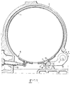
- la figure 1 est une coupe transversale de l'ensemble du dispositif d'attache d'un frein à bande selon l'invention;
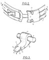
- la figure 2 est une vue en perspective du frein à bande;
- la figure 3 est une vue en perspective de la bielle de réaction selon l'invention.
- Le dispositif d'attache d'un frein à bande 1 selon l'invention, est représenté sur la figure 1. Ce frein à bande est monté sur une boîte de vitesses automatique et il est commandé par un vérin 18. L'ensemble du dispositif est disposé dans un carter 3.
- Selon l'invention, une bielle de réaction 2 est montée dans le carter 3 au moyen d'un axe 4.
- La bielle de réaction selon l'invention a :
- deux faces d'appui 14 qui sont orientées sensiblement radialement par rapport au tambour 6 du frein à bande 1, de manière à avoir une réaction sur l'extrémité 7 de la bande du frein 1;
- et une talonnette 8 qui transmet le couple de réaction à l'extrémité 7 de la bande par sa face supérieure 9, dont le plan passe par l'axe de rotation 10 de ladite bielle de réaction 2, de manière à avoir la garantie d'obtenir un couple de basculement ou de réaction, que génère la force d'action F₁ de la talonnette 8 sur le frein à bande 1. Cette force d'action F₁ est donnée par l'action F de réaction du frein à bande 1 sur les deux faces d'appui 14, à une distance R de l'axe de rotation 10.
- La bielle de réaction 2 est constituée par un moyeu 11 qui est monté sur l'axe 4. Ce moyeu 11 se prolonge par un bras 12, dont l'extrémité 13 possède un décrochement de manière à avoir la face d'appui 9 de la talonnette 8.
- Comme on peut le voir sur la figure 3, l'extrémité 13 du bras 12 de la bielle de réaction 2 est constitué par deux faces d'appui 14, qui sont disposées de part et d'autre d'une languette. Cette languette se prolonge en avant des faces d'appui 14, et elle constitue la talonnette 8.
- La bielle de réaction 2 comporte des pions de positionnement 15 du frein à bande 1. Ces pions de positionnement 15 coopèrent avec des encoches 17 qui sont aménagées dans le frein à bande 1, comme on peut le voir sur la figure 2. Les pions de positionnement 15 sont montés dans des logements 16, qui sont aménagés dans le bras 12 de la bielle de réaction 2.
Claims (6)
- Dispositif d'attache d'un frein à bande, caractérisé- en ce que l'extrémité de la bande du frein (1) présente une première face sensiblement radiale par rapport au tambour de frein et une seconde face orientée sensiblement selon la circonférence du tambour, et- en ce qu'il comporte une bielle de réaction (2) montée dans le carter (3) dudit frein au moyen d'un axe (4), la bielle (2) présentant d'une part deux faces d'appui (14) orientées sensiblement radialement par rapport au tambour (6) de manière à appliquer une réaction sur la première face de l'extrémité de la bande du frein (1), et d'autre part une talonnette (8), dont le plan passe par l'axe de rotation (10) de la bielle (2), de manière à transmettre un couple de réaction à la seconde face de l'extrémité de la bande du frein (1).
- Dispositif d'attache selon la revendication 1, caractérisé en ce que la bielle de réaction (2) est constituée par un moyeu (11) monté sur l'axe (4), ledit moyeu (11) se prolongeant par un bras (12) dont l'extrémité (13) possède un décrochement, de manière à avoir la face d'appui (9) de la talonnette (8).
- Dispositif d'attache selon la revendication 2, caractérisé en ce que l'extrémité (13) du bras (12) de la bielle de réaction (2) est constituée par deux faces d'appui (14) disposées de part et d'autre d'une languette qui se prolonge en avant desdites faces d'appui (14) et qui constituent la talonnette (8).
- Dispositif d'attache selon la revendication 1, caractérisé en ce que la bielle de réaction (2) comporte des pions de positionnement (15) du frein à bande (1), qui coopèrent avec des encoches (17) aménagées dans ledit frein à bande (1).
- Dispositif d'attache selon les revendications 2 et 4, caractérisé en ce que les pions de positionnement (15) sont montés dans des logements (16) aménagés dans le bras (12) de la bielle de réaction (2).
- Dispositif d'attache selon l'une des revendications précédentes, caractérisé en ce que le frein à bande est monté sur une boîte de vitesses automatique et est commandé par un vérin (18).
Applications Claiming Priority (2)
| Application Number | Priority Date | Filing Date | Title |
|---|---|---|---|
| FR9009103A FR2664952B1 (fr) | 1990-07-17 | 1990-07-17 | Dispositif d'attache d'un frein a bande. |
| FR9009103 | 1990-07-17 |
Publications (2)
| Publication Number | Publication Date |
|---|---|
| EP0467771A1 EP0467771A1 (fr) | 1992-01-22 |
| EP0467771B1 true EP0467771B1 (fr) | 1994-11-02 |
Family
ID=9398811
Family Applications (1)
| Application Number | Title | Priority Date | Filing Date |
|---|---|---|---|
| EP19910401975 Expired - Lifetime EP0467771B1 (fr) | 1990-07-17 | 1991-07-16 | Dispositif d'attache d'un frein à bande |
Country Status (3)
| Country | Link |
|---|---|
| EP (1) | EP0467771B1 (fr) |
| DE (1) | DE69104926T2 (fr) |
| FR (1) | FR2664952B1 (fr) |
Families Citing this family (2)
| Publication number | Priority date | Publication date | Assignee | Title |
|---|---|---|---|---|
| US5347702A (en) * | 1990-06-28 | 1994-09-20 | Borg-Warner Automotive Transmission & Engine Components Corporation | Method of producing a transmission brake band |
| CN111963588B (zh) * | 2020-07-17 | 2021-11-02 | 北京理工大学 | 一种外抱带式浮动齿形换挡制动器 |
Family Cites Families (2)
| Publication number | Priority date | Publication date | Assignee | Title |
|---|---|---|---|---|
| US3399749A (en) * | 1966-10-31 | 1968-09-03 | Borg Warner | Flexible resilient brake band |
| US4456100A (en) * | 1981-08-04 | 1984-06-26 | Kabushiki Kaisha Daikin Seisakusho | Band brake mechanism for an automatic transmission of an automobile |
-
1990
- 1990-07-17 FR FR9009103A patent/FR2664952B1/fr not_active Expired - Lifetime
-
1991
- 1991-07-16 DE DE1991604926 patent/DE69104926T2/de not_active Expired - Lifetime
- 1991-07-16 EP EP19910401975 patent/EP0467771B1/fr not_active Expired - Lifetime
Also Published As
| Publication number | Publication date |
|---|---|
| FR2664952B1 (fr) | 1992-10-09 |
| FR2664952A1 (fr) | 1992-01-24 |
| DE69104926D1 (de) | 1994-12-08 |
| DE69104926T2 (de) | 1995-05-24 |
| EP0467771A1 (fr) | 1992-01-22 |
Similar Documents
| Publication | Publication Date | Title |
|---|---|---|
| EP0080950B2 (fr) | Frein à disque à étrier monté coulissant | |
| EP0694133B1 (fr) | Frein a disque utilisant un patin tire a appui permanent | |
| EP4058853B1 (fr) | Mobile d'embrayage unidirectionnel, notamment pour l'horlogerie | |
| FR2626053A1 (fr) | Embrayage de verrouillage pour appareil d'accouplement hydrocinetique, notamment pour vehicule automobile | |
| EP0467771A1 (fr) | Dispositif d'attache d'un frein à bande | |
| FR2613444A1 (fr) | Levier d'embrayage a rapport variable, embrayage l'employant et procede de controle de la force requise pour le debrayage | |
| FR2791406A1 (fr) | Dispositif de montage d'un diaphragme sur un couvercle d'embrayage | |
| EP0204604A1 (fr) | Ressort de plaque de poussée pour frein à disque | |
| FR2691771A1 (fr) | Commande d'embrayage, en particulier pour embrayages de véhicules automobiles. | |
| EP0326774B1 (fr) | Frein à disque et patin de frein utilisable dans un tel frein | |
| EP0018913B1 (fr) | Frein à disque | |
| WO1996041966A1 (fr) | Frein a disque utilisant un patin sollicite en rotation | |
| FR2919032A1 (fr) | Mecanisme perfectionne pour embrayage, notamment de vehicule automobile | |
| FR2753759A1 (fr) | Agencement de plateau de pression pour embrayage a friction a compensation d'usure | |
| WO2000022314A1 (fr) | Embrayage a friction associe a un dispositif de detection d'usure | |
| EP0320364B1 (fr) | Butée de débrayage actionnée par traction | |
| FR2558228A1 (fr) | Butee de debrayage | |
| FR3074550A1 (fr) | Systeme d'actionnement d'un mecanisme d'embrayage comprenant un dispositif d'appui axial | |
| EP0320365B1 (fr) | Butée de débrayage actionnée par traction | |
| FR2722262A1 (fr) | Dispositif de commande d'embrayage | |
| EP1721795B1 (fr) | Dispositif et procédé de fixation d'un mécanisme d'essuie-vitre sur une partie de caisse de véhicule, et véhicule automobile équipé d'un tel dispositif | |
| FR2533281A2 (fr) | Butee de debrayage, notamment pour vehicule automobile et son procede de montage | |
| FR2484927A2 (fr) | Dispositif d'entrainement d'accessoires de vehicules automobiles | |
| FR2503297A1 (fr) | Butee de debrayage, notamment pour vehicules automobiles | |
| FR2558906A1 (fr) | Embrayage a friction muni de ressorts lames tangentiels |
Legal Events
| Date | Code | Title | Description |
|---|---|---|---|
| PUAI | Public reference made under article 153(3) epc to a published international application that has entered the european phase |
Free format text: ORIGINAL CODE: 0009012 |
|
| AK | Designated contracting states |
Kind code of ref document: A1 Designated state(s): DE GB |
|
| 17P | Request for examination filed |
Effective date: 19920626 |
|
| 17Q | First examination report despatched |
Effective date: 19930728 |
|
| GRAA | (expected) grant |
Free format text: ORIGINAL CODE: 0009210 |
|
| AK | Designated contracting states |
Kind code of ref document: B1 Designated state(s): DE GB |
|
| GBT | Gb: translation of ep patent filed (gb section 77(6)(a)/1977) |
Effective date: 19941107 |
|
| REF | Corresponds to: |
Ref document number: 69104926 Country of ref document: DE Date of ref document: 19941208 |
|
| PGFP | Annual fee paid to national office [announced via postgrant information from national office to epo] |
Ref country code: GB Payment date: 19950615 Year of fee payment: 5 |
|
| PLBE | No opposition filed within time limit |
Free format text: ORIGINAL CODE: 0009261 |
|
| STAA | Information on the status of an ep patent application or granted ep patent |
Free format text: STATUS: NO OPPOSITION FILED WITHIN TIME LIMIT |
|
| 26N | No opposition filed | ||
| PG25 | Lapsed in a contracting state [announced via postgrant information from national office to epo] |
Ref country code: GB Effective date: 19960716 |
|
| GBPC | Gb: european patent ceased through non-payment of renewal fee |
Effective date: 19960716 |
|
| PGFP | Annual fee paid to national office [announced via postgrant information from national office to epo] |
Ref country code: DE Payment date: 20100723 Year of fee payment: 20 |
|
| REG | Reference to a national code |
Ref country code: DE Ref legal event code: R071 Ref document number: 69104926 Country of ref document: DE |
|
| REG | Reference to a national code |
Ref country code: DE Ref legal event code: R071 Ref document number: 69104926 Country of ref document: DE |
|
| PG25 | Lapsed in a contracting state [announced via postgrant information from national office to epo] |
Ref country code: DE Free format text: LAPSE BECAUSE OF EXPIRATION OF PROTECTION Effective date: 20110717 |