EP0467673B1 - Elevator active suspension system - Google Patents
Elevator active suspension system Download PDFInfo
- Publication number
- EP0467673B1 EP0467673B1 EP91306517A EP91306517A EP0467673B1 EP 0467673 B1 EP0467673 B1 EP 0467673B1 EP 91306517 A EP91306517 A EP 91306517A EP 91306517 A EP91306517 A EP 91306517A EP 0467673 B1 EP0467673 B1 EP 0467673B1
- Authority
- EP
- European Patent Office
- Prior art keywords
- car
- signal
- sensed
- responsive
- magnitude
- Prior art date
- Legal status (The legal status is an assumption and is not a legal conclusion. Google has not performed a legal analysis and makes no representation as to the accuracy of the status listed.)
- Expired - Lifetime
Links
- 239000000725 suspension Substances 0.000 title claims description 46
- 230000001133 acceleration Effects 0.000 claims description 128
- 230000004907 flux Effects 0.000 claims description 41
- 230000005291 magnetic effect Effects 0.000 claims description 18
- 238000010304 firing Methods 0.000 claims description 12
- 230000000087 stabilizing effect Effects 0.000 claims description 5
- 230000003247 decreasing effect Effects 0.000 claims description 3
- 238000001914 filtration Methods 0.000 claims description 2
- 230000010363 phase shift Effects 0.000 claims 2
- 230000004044 response Effects 0.000 description 36
- 238000006243 chemical reaction Methods 0.000 description 29
- 238000013459 approach Methods 0.000 description 27
- 230000033001 locomotion Effects 0.000 description 24
- 230000005294 ferromagnetic effect Effects 0.000 description 22
- 230000001276 controlling effect Effects 0.000 description 21
- 238000000034 method Methods 0.000 description 18
- 230000000694 effects Effects 0.000 description 16
- 238000013461 design Methods 0.000 description 15
- 238000010586 diagram Methods 0.000 description 11
- 230000005484 gravity Effects 0.000 description 10
- NJPPVKZQTLUDBO-UHFFFAOYSA-N novaluron Chemical compound C1=C(Cl)C(OC(F)(F)C(OC(F)(F)F)F)=CC=C1NC(=O)NC(=O)C1=C(F)C=CC=C1F NJPPVKZQTLUDBO-UHFFFAOYSA-N 0.000 description 10
- 230000006870 function Effects 0.000 description 9
- 230000006641 stabilisation Effects 0.000 description 9
- 238000011105 stabilization Methods 0.000 description 9
- 238000013519 translation Methods 0.000 description 8
- 230000014616 translation Effects 0.000 description 8
- 230000005355 Hall effect Effects 0.000 description 7
- 101500022510 Lithobates catesbeianus GnRH-associated peptide 2 Proteins 0.000 description 7
- 230000008901 benefit Effects 0.000 description 7
- 230000002829 reductive effect Effects 0.000 description 7
- 229910000831 Steel Inorganic materials 0.000 description 6
- 238000012937 correction Methods 0.000 description 6
- 238000013016 damping Methods 0.000 description 6
- 238000006073 displacement reaction Methods 0.000 description 6
- 239000010959 steel Substances 0.000 description 6
- 101500023488 Lithobates catesbeianus GnRH-associated peptide 1 Proteins 0.000 description 5
- 230000008859 change Effects 0.000 description 5
- 230000000116 mitigating effect Effects 0.000 description 5
- 238000012545 processing Methods 0.000 description 5
- 230000035939 shock Effects 0.000 description 5
- 238000012360 testing method Methods 0.000 description 5
- 239000006096 absorbing agent Substances 0.000 description 4
- 239000002131 composite material Substances 0.000 description 4
- 210000001503 joint Anatomy 0.000 description 4
- 230000008569 process Effects 0.000 description 4
- 229910052761 rare earth metal Inorganic materials 0.000 description 4
- 230000009467 reduction Effects 0.000 description 4
- 230000035945 sensitivity Effects 0.000 description 4
- 238000004088 simulation Methods 0.000 description 4
- 230000009471 action Effects 0.000 description 3
- 230000000052 comparative effect Effects 0.000 description 3
- 230000003750 conditioning effect Effects 0.000 description 3
- 230000001419 dependent effect Effects 0.000 description 3
- 239000000463 material Substances 0.000 description 3
- 241000972773 Aulopiformes Species 0.000 description 2
- RYGMFSIKBFXOCR-UHFFFAOYSA-N Copper Chemical compound [Cu] RYGMFSIKBFXOCR-UHFFFAOYSA-N 0.000 description 2
- XEEYBQQBJWHFJM-UHFFFAOYSA-N Iron Chemical compound [Fe] XEEYBQQBJWHFJM-UHFFFAOYSA-N 0.000 description 2
- 241000269319 Squalius cephalus Species 0.000 description 2
- 238000004458 analytical method Methods 0.000 description 2
- 238000004422 calculation algorithm Methods 0.000 description 2
- 239000003638 chemical reducing agent Substances 0.000 description 2
- KPLQYGBQNPPQGA-UHFFFAOYSA-N cobalt samarium Chemical compound [Co].[Sm] KPLQYGBQNPPQGA-UHFFFAOYSA-N 0.000 description 2
- 229910052802 copper Inorganic materials 0.000 description 2
- 239000010949 copper Substances 0.000 description 2
- 206010016256 fatigue Diseases 0.000 description 2
- 230000006698 induction Effects 0.000 description 2
- 238000012806 monitoring device Methods 0.000 description 2
- -1 rare earth compound Chemical class 0.000 description 2
- 230000001105 regulatory effect Effects 0.000 description 2
- 230000002441 reversible effect Effects 0.000 description 2
- 235000019515 salmon Nutrition 0.000 description 2
- 229910000938 samarium–cobalt magnet Inorganic materials 0.000 description 2
- 238000012546 transfer Methods 0.000 description 2
- 238000004804 winding Methods 0.000 description 2
- 238000012935 Averaging Methods 0.000 description 1
- 101100282116 Candida albicans (strain SC5314 / ATCC MYA-2876) GAP4 gene Proteins 0.000 description 1
- 101100282115 Candida albicans (strain SC5314 / ATCC MYA-2876) HIP1 gene Proteins 0.000 description 1
- 229920001875 Ebonite Polymers 0.000 description 1
- 241000286894 Otala Species 0.000 description 1
- 229910000746 Structural steel Inorganic materials 0.000 description 1
- 230000032683 aging Effects 0.000 description 1
- 230000002238 attenuated effect Effects 0.000 description 1
- 230000003416 augmentation Effects 0.000 description 1
- 230000000903 blocking effect Effects 0.000 description 1
- 238000004364 calculation method Methods 0.000 description 1
- 238000010276 construction Methods 0.000 description 1
- 230000008602 contraction Effects 0.000 description 1
- 238000005520 cutting process Methods 0.000 description 1
- 238000011161 development Methods 0.000 description 1
- 230000018109 developmental process Effects 0.000 description 1
- 238000005553 drilling Methods 0.000 description 1
- 230000009977 dual effect Effects 0.000 description 1
- 239000003302 ferromagnetic material Substances 0.000 description 1
- 101150112629 gap3 gene Proteins 0.000 description 1
- 238000005470 impregnation Methods 0.000 description 1
- 230000006872 improvement Effects 0.000 description 1
- 238000009413 insulation Methods 0.000 description 1
- 230000010354 integration Effects 0.000 description 1
- 230000003993 interaction Effects 0.000 description 1
- 229910052742 iron Inorganic materials 0.000 description 1
- 238000003475 lamination Methods 0.000 description 1
- 230000000670 limiting effect Effects 0.000 description 1
- 238000003754 machining Methods 0.000 description 1
- 230000005415 magnetization Effects 0.000 description 1
- 238000004519 manufacturing process Methods 0.000 description 1
- 230000013011 mating Effects 0.000 description 1
- 238000005259 measurement Methods 0.000 description 1
- 230000007246 mechanism Effects 0.000 description 1
- 238000003801 milling Methods 0.000 description 1
- 239000000203 mixture Substances 0.000 description 1
- 239000013642 negative control Substances 0.000 description 1
- 230000003287 optical effect Effects 0.000 description 1
- 230000010355 oscillation Effects 0.000 description 1
- 238000012856 packing Methods 0.000 description 1
- 230000036961 partial effect Effects 0.000 description 1
- 239000013641 positive control Substances 0.000 description 1
- 230000036316 preload Effects 0.000 description 1
- 230000002035 prolonged effect Effects 0.000 description 1
- 230000001681 protective effect Effects 0.000 description 1
- 150000002910 rare earth metals Chemical class 0.000 description 1
- 238000011084 recovery Methods 0.000 description 1
- 239000007787 solid Substances 0.000 description 1
- 230000007480 spreading Effects 0.000 description 1
- 238000003892 spreading Methods 0.000 description 1
- 230000003068 static effect Effects 0.000 description 1
- 238000003860 storage Methods 0.000 description 1
- 230000009466 transformation Effects 0.000 description 1
- 230000007704 transition Effects 0.000 description 1
- 239000011800 void material Substances 0.000 description 1
Images

















Classifications
-
- B—PERFORMING OPERATIONS; TRANSPORTING
- B66—HOISTING; LIFTING; HAULING
- B66B—ELEVATORS; ESCALATORS OR MOVING WALKWAYS
- B66B7/00—Other common features of elevators
- B66B7/02—Guideways; Guides
- B66B7/022—Guideways; Guides with a special shape
-
- B—PERFORMING OPERATIONS; TRANSPORTING
- B66—HOISTING; LIFTING; HAULING
- B66B—ELEVATORS; ESCALATORS OR MOVING WALKWAYS
- B66B11/00—Main component parts of lifts in, or associated with, buildings or other structures
- B66B11/02—Cages, i.e. cars
- B66B11/026—Attenuation system for shocks, vibrations, imbalance, e.g. passengers on the same side
- B66B11/028—Active systems
- B66B11/0286—Active systems acting between car and supporting frame
-
- B—PERFORMING OPERATIONS; TRANSPORTING
- B66—HOISTING; LIFTING; HAULING
- B66B—ELEVATORS; ESCALATORS OR MOVING WALKWAYS
- B66B7/00—Other common features of elevators
- B66B7/02—Guideways; Guides
- B66B7/04—Riding means, e.g. Shoes, Rollers, between car and guiding means, e.g. rails, ropes
- B66B7/041—Riding means, e.g. Shoes, Rollers, between car and guiding means, e.g. rails, ropes including active attenuation system for shocks, vibrations
- B66B7/042—Riding means, e.g. Shoes, Rollers, between car and guiding means, e.g. rails, ropes including active attenuation system for shocks, vibrations with rollers, shoes
-
- B—PERFORMING OPERATIONS; TRANSPORTING
- B66—HOISTING; LIFTING; HAULING
- B66B—ELEVATORS; ESCALATORS OR MOVING WALKWAYS
- B66B7/00—Other common features of elevators
- B66B7/02—Guideways; Guides
- B66B7/04—Riding means, e.g. Shoes, Rollers, between car and guiding means, e.g. rails, ropes
- B66B7/046—Rollers
Definitions
- This invention relates to elevators and, more particularly, improved ride quality.
- Conventional elevator system suspensions can be characterized by the mechanical properties of the transmissive elements which connect three major elevator components: the car platform, the supporting frame, and the guide rails.
- the conventional elevator car platform is typically attached to the supporting frame with hard rubber pads.
- the frame runs along the guide rails, and is supported either by stiffly sprung wheels or sliding gibs at four attachment points.
- U.S. Patent No. 4,754,849, Hiroshi Ando shows electromagnets disposed outside the car symmetrically about guide rails in a control system using opposing forces from the electromagnets to keep the car steady using the rails as the necessary ferromagnetic mass but, rather than using the rails as a straight reference line, instead using a cable stretched between the top and bottom of the hoistway.
- the position of the car with respect to the cable is controlled using detectors in a closed loop control system. There is serious question as to whether such a cable can be successfully used as a reliable guide of straightness, especially in tall buildings.
- U.S. Patent No. 4,750,590, Matti Otala discloses what appears to be an essentially open loop control system with solenoid actuated guide shoes that uses the concept of memorizing the out-of-straightness of the guide rails for storage in a computer memory and then sensing the position of the car in the hoistway for the purpose of recalling the corresponding information from memory and correcting the guide rail shoe positions accordingly.
- An acceleration sensor is mentioned in claim 6 but does not appear to be otherwise disclosed as to its purpose in the specification or drawing. Perhaps it is used to determine the acceleration of the car in the hoistway. Such an acceleration signal would presumably be needed to determine which data point to retrieve from memory as suggested in claim 2.
- Otala's approach suffers from the problem of changes in the out-of-straightness before a correction run can be effected and the accuracy with which the stored information can be made to conform to the car's actual position.
- a mounting arrangement for a pendulum-type or hung cab is shown in U.S. Patent 4,113,064 by Shigeta et al wherein the cab is suspended within and from the top of an outer car framework by a plurality of rods connected to the bottom of the cab.
- a plurality of stabilizing stoppers are shown interposed between the underside of the hung cab and the floor of the car frame.
- Each stopper comprises a cylinder extending downward from the underside of the hung cab surrounding a rubber torus placed on an upright rod extending from the floor of the car frame. Clearance between the cylinder and the hung cab is sufficient to permit movement but insufficient to allow the hung cab to strike the car frame.
- Another embodiment comprising "bolster" means having ball bearings permits movement in any direction of the horizontal plane.
- AU-A-41565/89 to Kahkipuro discloses a procedure for damping vertical vibrations of an elevator car supported by elastic suspension elements comprising the steps of measuring the acceleration and using the output signal form the accelerometer to control at least one vibration damper in the vertical direction.
- a high pass filter is disclosed for blocking the passage of low frequency vertical accelerations relating to normal starting and stopping accelerations of the elevator. Only vibration frequencies higher than 1 Hertz are passed through the high pass filter to be effectively absorbed by the damper. It is stated on page 8 of Kahkipuro, lines 24-34, that vibrations may be suppressed in all three dimensions but that for other dimensions (which are not disclosed in detail), signal transducers measuring acceleration in the other two directions need not be filtered.
- Kakipuro disclosure does not go into any further detail as to the purpose for an acceleration measurement in the horizontal direction nor as to what kind of signal conditioning would be needed in the horizontal plane. Indeed, Kahkiputo teaches that no signal conditioning whatsoever need be employed in the horizontal plane, not even filters. Moreover, even if a purpose were disclosed, there is no teaching regarding the problem of how to use acceleration control as a soft spring for vibration purposes while at the same time providing a stiff spring for leveling or centering purposes. Both of these problems must be addressed in order to sucessfully control vibrations in the horizontal plane.
- tunable shock absorbers are used as tunable impedances. They comprise a relative displacement device made up, from a “systems” point of view, of a mechanical impedance (defined here as the frequency dependent ratio of deflection over applied force) of a stiffness in parallel with a damper. The stiffness and dampening elements are adjusted during different conditions. For example, during a cornering mode, as sensed by accelerometers, increased stiffness is desired on selected shock absorbers. Similarly, during braking, both front shocks are made stiffer. This is done in software by sensing the displacement of the car with respect to the frame and commanding a desired displacement.
- Klinger et al discloses an acceleration sensor 26 which feeds a microprocessor which in turn appears to control an actuator for a motor vehicle suspension unit.
- Fig. 2 shows an accelerometer feedback signal between a strut control processor 20 and a strut assembly 10 connected between each wheel 14 and the chassis, i.e., the frame 12 of a motor vehicle.
- Soltis discloses an acceleration sensor 16 in Fig. 2 providing a signal to a suspension control module for a multi-stable suspension unit.
- Ross et al discloses a lateral accelerometer 40′ in Fig. 6 which shows interconnecting components insertable at the Z-Z′ inputs of Fig. 4 to include lateral stability. Also, see Fig. 4 for an illustration of an electromagnetic side frame 1 and a ferromagnetic side frame 2 as part of a block diagram of a complete electrical control system comprising an active suspension for a railway truck shown in Fig. 2.
- Williams et al illustrates control signals that can be modified by signals representing vehicle speed and lateral and longitudinal acceleration.
- Kolm et al discloses active damping of oscillations of a magnetically levitated vehicle including inertial and position sensors on the vehicle.
- Sugasawa et al discloses an automotive suspension control system with vibration sensors for detecting road surface conditions and counteracting same.
- Pollard et al discloses an active suspension for a vehicle in which an accelerometer 3 is utilized.
- Clark et al discloses an "active" suspension system between the body and wheel of a vehicle.
- a high gain closed positional velocity servoloop is disclosed.
- An object of the present invention is to improve the ride quality of elevators.
- cab refers to a passenger platform suspended or movably supported within an outer frame.
- Car refers to a passenger platform that is not free to move within a supporting frame or on another supporting platform, or alternately, “car” is used to refer to a frame for a movably supported or suspended cab platform (e.g., "car frame”).
- an elevator car including apparatus for stabilizing the car, the apparatus comprising:
- control is responsive to the sensed signals to process the sensed signals to drive the actuator with a frequency response tailored to achieve a stable, high-performance, drift-free system.
- the loop gain is made greater than 1. At high frequencies, the loop gain is rolled off to meet stability robustness requirements. At low frequencies, the loop gain is "washed-out" to reduce the effects of sensor noise and drift.
- the elevator active suspension system disclosed herein represents a combination of sensors, a control, and an actuator applied in one or more axes to minimize the effects of rail-induced disturbances and direct car forces.
- An elevator in going up and down a hoistway, is subjected to disturbances due to rail irregularities which have a frequency content not unlike the disturbances caused by other forces, which we call direct forces.
- the frequency content of rail-induced disturbances is in the same range of frequencies encountered at the same time in the disturbances caused by direct forces.
- Direct forces can be most effectively countered by high mechanical impedance, while rail irregularities can be effectively countered by low mechanical impedance.
- there are well defined modes to detect such as cornering, acceleration and deceleration, which may be effectively counteracted using the tunable impedance as previously described.
- the actuators may be arranged, for a conventional car embodiment, so as to counteract horizontal translational forces acting on the car moving in the hoistway or, for nonconventional hung (pendulum) or supported cab embodiments, arranged to counteract horizontal forces acting on the hung or supported cab moving in the car frame as the frame moves in the hoistway. If such a concept is utilized in a conventional car application, it would require only four active actuators near the bottom of the car, two each for actuating rails on opposite sides of the car. Four conventional or passive guides might additionally be used near the top of the car. Such an arrangement might advantageously employ, e.g.
- V rail shape e.g., a shape first suggested for other purposes by Charles R. Otis in U.S. Patent No. 134,698 (which issued on January 7, 1873). If such a concept is utilized in a pendulum or supported cab application it similarly might require, without limitation, only four actuators using an active actuator arrangement on or near the bottom of the cab for actuating the car frame and, also without limitation, using conventional rails for guiding the frame.
- the actuators may be arranged so as to counteract rotational forces acting about vertical on the conventional car in a hoistway or a cab hung from, or supported on, a car frame. Furthermore, if such a concept is utilized for controlling a conventional car in a hoistway it still would only require four actuators using the same novel rail shape for active control. If such a concept is utilized in a pendulum or supported cab application, it similarly still requires only four actuators using a active actuator arrangement and, without limitation, using conventional rails for guiding the frame.
- the actuators may be arranged so as to counteract rotational forces acting on a conventional car, or on a cab hung from or supported on a frame, about one or more axes in a horizontal plane.
- Such axes may, but need not, be defined for purposes of control as orthogonal axes in such a horizontal plane and which may be parallel to the hoistway walls.
- a plurality of actuators may be employed at both the top and bottom of the car wherein those at the top control horizontal accelerations in the roof while those at the bottom control horizontal accelerations in the floor. By independently controlling horizontal accelerations in the top and bottom, rotations are automatically taken care of.
- the actuators may be of the electromagnetic type.
- the actuators may be electromechanical, e.g., solenoid actuated wheels.
- four electromagnetic actuators are utilised, each operating along an axis which, for a non-pendulum or non-frame-supported car embodiment, is disposed for imparting forces at an angle of forty-five degrees to a hoistway wall, e.g., opposite hoistway-railed walls and, for the hung cab embodiment, is disposed for imparting forces along axes at an angle of forty-five degrees to the planes of the hung or supported cab walls.
- the present invention teaches, among other things, that, instead of position, accelerometers are most advantageously used in a closed loop for actively controlling an elevator car or cab. It further teaches that, for a car guided by rails mounted on hoistway walls, Ando's twelve electromagnets for controlling horizontal translations of an elevator car can be replaced by a lesser number of actuators. According to a preferred embodiment of an aspect of the present invention, four actuators are sufficient for controlling such translational forces in the horizontal plane. Moreover, as a further teaching, the same four actuators may be used to control rotational forces about vertical.
- a new rail configuration may be advantageously applied in an active system based on acceleration feedback, and four or more actuators may be well-disposed for controlling translational forces in the horizontal plane.
- the same actuators may be used to control rotational forces about vertical.
- the same teachings may be extended for application to a cab hung or supported in a car frame. In such a case, four or more well-disposed actuators are similarly sufficient for controlling translational forces in the horizontal plane.
- the same actuators may be used to control rotational forces about vertical.
- a preferred embodiment comprises a relatively fast, simple, analog control loop responsive to accelerometers with one or more, relatively slower, but more accurate, digital control loops responsive to position or acceleration sensors or to both.
- Another preferred embodiment of the present invention originated from the need to improve the combined strength to weight ratio of the guide rails, without lessening their control characteristics.
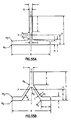
- This embodiment of the present invention achieves this goal by using a "Y" shaped section rail in place of the standard "T" shaped guide rail.
- the guide rail may interface with three wheels attached to the elevator car, in which the three wheels ride on comparable surfaces to that of the "T” shape, namely on two, opposed sides of the base, but with the mounting surface being through the upper part of the "Y” through the legs of the "Y”, which form a "V”, instead of the flat, orthogonally disposed "top” of the "T".
- Such may be embodied in two or three actively controlled wheels or other actuators such as electromagnets using the "T's" upright portion or the top part of the "Y" as ferromagnetic masses.
- the Y-shape has better section properties than a corresponding T-shape yet weighs considerably less. This saving in weight, while retaining the section properties, is achieved by spreading the material in the two legs of the "Y".
- the T-section has more material, below the blade, concentrated near the center line and thus contributes less to the moment of inertia of the section about the center line.
- the material below the blade is spread in the two legs of the "Y" and further away from the center line. They contribute more to the moment of inertia of the section about the center line. Consequently, a Y-shape having the same section properties is lighter than the corresponding T-shape.
- Appropriately configured "Y" shaped guide rails can replace the T-shapes, with a savings in weight of, for example, ten to twenty percent (10% to 20%).
- the passive restraints employed by Shigeta et al and Luinstra et al are not as effective as the present invention in that they do not actively counteract the undesirable translational forces to which the cab is subjected and thus do not provide as smooth a ride for the passenger as that provided by the present invention. Furthermore, they do not actively counteract the undesirable rotational forces to which the cab is subjected and thus similarly fail to provide as smooth a ride for the passenger as that provided by the present invention. And certainly they do not consider even passive restraints arid certainly not active countermeasures of any kind with respect to rotational axes other than vertical, as taught herein.
- a passenger platform 10 for an elevator car or cab is suspended or supported by means 12.
- cab refers to a passenger platform suspended or movably supported within an outer frame (not shown in Fig. 1).
- Car refers to a passenger platform that is not movably supported within a frame or, alternatively, to a frame for a suspended or supported cab platform (sometimes referred to as a "car frame”).
- each term is: (i) a car suspended by a cable laid over a rotating sheave, (ii) a ("pendulum") cab suspended by a cable, rod or rods within a car frame, (iii) a car supported on a movable platform mounted on a hydraulically operated piston, (iv) a cab supported on a movable platform in a supported or suspended car frame, etc.
- the elevator car or car frame is moved up and down in an elevator hoistway (not shown in Fig. 1) guided by means such as vertical rails (not shown) attached to the hoistway walls.
- one or more disturbances 14 may be sensed by a sensor 16 disposed in or on the car or cab platform 10.
- the sensor 16 typically senses an effect of the disturbance 14 for providing a signal having a magnitude indicative of the magnitude of the effect on a line 18.
- Means 20 is responsive to the signal provided on line 18 for determining the magnitude of the response required to counteract the sensed effect of the disturbance and for providing a signal on a line 22 for commanding an actuator 24 to actuate the platform 10 as indicated by an actuation signal on a line 26.
- the actuator 24 may be disposed, without limitation, between the car or car frame and the hoistway or it may be disposed between the car frame and the cab inside the frame for imparting forces therebetween in response to the control signal on line 22.
- a plurality of sensors similar to sensor 16 may be disposed to be responsive to one or more selected parameters indicative of translational and rotational movements of the car or cab which cause it to deviate from staying perfectly centered on an imaginary vertical line through the center of the hoistway.
- Such sensors may be responsive to any one or any number of selected parameters such as the position of the car or cab with respect to the hoistway, the translational accelerations experienced by the car or cab, etc. According to the present invention, acceleration is sensed.
- Such sensors may provide one or more sensed signals to the means 20 or another similar means in order to complete a closed loop for purposes of automatic feedback control, according to the present invention.
- one way to view a preferred embodiment of the invention is to think of the control system as causing the elevator car's vertical centerline (or elevator frame-suspended or frame-supported cab's vertical centerline) to remain coincident with an imaginary, stationary reference line up the center of the hoistway, without the suspended car or cab's centerline departing from coincidence with the hoistway reference centerline or without the car or cab, having its centerline coincident with the stationary centerline, from rotating about the stationary centerline.
- Fig. 2 illustrates car or cab mounted accelerometers 16a, 16b, 16c which together serve as an example of a sensor arrangement that may be used to sense horizontal accelerations manifesting small horizontal translations causing deviations of the car or cab's centerline from the hoistway's centerline and, without necessarily limiting the foregoing, by further sensing accelerations manifesting small rotations of the car or cab about the hoistway centerline.
- An additional set of similar sensors 16d, 16e, 16f may, but need not, be located near the top of the car or cab.
- actuator groups 24a, 24b, 24c, 24d permit the exertion of forces to maintain the desired coincidence of the car or cab and hoistway centerlines and, if desired, with no rotation about vertical or even about one or more axes in the horizontal plane.
- a preferred embodiment of the present invention utilizes two groups of actuators 24a, 24b, e.g., each group comprising a pair of actuators.
- two groups of actuators are shown near both the top and the bottom of the car or cab, it should be understood that such are shown to indicate actuators acting from any position or in any grouping, i.e., other groupings at other positions are certainly encompassed by the claims of the present invention.
- the preferred embodiment only uses actuators at the bottom. The fact that the actuators are shown detached from the platform ⁇ implying electromagnetic actuators utilizing a contactless (air gap) form ⁇ in no way excludes actuators mechanically attached to the platform.
- FIG. 2 An arbitrary three dimensional coordinate system illustration 44 in Fig. 2 has its x-z plane in the paper and should be thought of as having its origin in the center of gravity of the car or cab 10 and having its minus y-axis pointing up perpendicular to the paper toward the reader.
- the coordinate system 44 of Fig. 2 is illustrated in more detail in Fig. 3.
- rotations about the vertical z-axis there may be rotations about the x and y-axes which may also be controlled, according to the present invention, if desired.
- translations in the horizontal plane may be controlled using the apparatus shown. Such may also, but need not be, used for controlling rotations.
- the present invention may be used to control rotations in the horizontal plane and may be extended to two or even to a plurality of axes including an additional horizontal axis and a vertical axis.
- the accelerometers cannot be positioned at the center of gravity as would be desired.
- a floor or roof of a passenger compartment is illustrated here without limitation as an acceptable compromise.
- the selected positioning of the illustrated sensors is of course arbitrary. It should not be inferred from the symmetry of such positioning with respect to the illustrated coordinate system, or to each other, that the selected relationship is required to practice the claimed invention.
- sensors could be aligned for sensing accelerations along axes parallel to or coincident with the axes of actuation, i.e., forty-five degrees with respect to the hoistway walls.
- the orientation of the actuators at forty-five degree angles with respect to the hoistway walls is not absolutely essential. Indeed, the relationships of the actuators to the car or cab are not critical. It is preferred, however, to have orthogonality of actuators to achieve universal force vector capability and to have a distance between lines of opposite force to enable torque development. Thus, one could arrange the actuators in each corner to act along the diagonals instead of perpendicularly thereto. Although such an arrangement is not presently preferred as it would eliminate the capability to counter vertical rotations, it would still fall within the scope of the claims hereof.
- guide rails are not illustrated, such would typically be situated oppositely on two of the four hoistway walls.
- Such may, for a car example, serve as ferromagnetic masses for use, for example, by the actuators 24a, 24b, 24c, 24d should the actuators be of the electromagnetic type.
- the actuators 24a, 24b can be attached near the bottom and 24c, 24d near the top of the platform 10 for producing magnetic flux for contactless interaction across air gaps with the rails.
- electromechanical i.e., contact-type active actuators, to be disclosed below, can be employed.
- Conventional, passive-type wheel guides can be used instead of active actuators 24c, 24d at opposite sides at the top of the car to lend additional stability without adding the need for additional active control systems as required by Ando, for example, but for his more limited purposes.
- electromagnetic, contactless-type actuators 24a, 24b can be attached to the underside of the cab with suitable ferromagnetic reaction plates erected on the floor of the car frame for providing a path for magnetic flux provided by the actuators. In such a case, there would be no need for additional passive guides at the top of the cab.
- electromagnetic, contactless-type actuators 24a, 24b can be attached to the underside of the sliding platform with suitable ferromagnetic reaction plates erected under the sliding platform on a nonsliding horizontal platform mounted on the top of the piston or, for a supported cab, on the floor of the car frame, for providing a path for magnetic flux provided by the actuators.
- a preferred embodiment of a present invention may be utilized for increasing ride comfort in an elevator car or cab.
- the preferred embodiment of the present invention will be described first for a cab and then for a car. It will become apparent that the same approach is used for both the car and cab, differing in detail only to the extent necessary to account for the fact that the actuators for a car act against a rail on a hoistway wall, as shown in Fig. 15, while the actuators for a cab act on a frame as shown in Figs. 14B, 14C, and 14D.
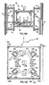
- Fig. 14A is a top view and Fig. 14B is a side view of a pendulum car 46. It includes an active suspension system comprising an actuator 45 shown in Fig. 14B, driven by a control (not shown) to process sensed data relative to the motion of a platform 10b. Sensors 50, 52, 54, which are accelerometers, measure the platform motion. The platform 10b is suspended by rods 56, 58 from a frame 60 which is suspended by a cable 62 for moving the car 46 up and down in an elevator hoistway having walls 64, 66 with rails 68, 70 mounted thereon. A plurality of wheels 72, 74, 76, 78 are mounted by means of springs 80, 82, 84, 86 to the frame 60. A passive pendulum car of this type (without the actuator 45) is shown in detail in U.S. Patent 4,899,852.
- the wheels are subjected to bumpiness in the rails, e.g., caused by a rail butt joint misalignment 88 or waviness 90.
- Such butt joint irregularities induce relatively high frequency car vibrations, while waviness usually produces lower frequency vibrations.
- the platform 10b is subjected to what we call direct forces 92, which may comprise a large number of different influences, including wind forces, motion of people within the car standing on the platform, and numerous other similar "direct" forces.
- a coordinate system is shown in both Figs. 14A and 14B (similar to Fig. 2) and shows an X-Y plane in the floor of the platform 10b with the Z-axis in the vertical direction.
- the present invention mitigates both direct forces and rail irregularity forces imparted to the platform 10b through the frame 60. It does this by counteracting lateral forces in both the X and Y directions. Rotations about the Z-axis are mitigated also by virtue of lateral control along the X and Y axes as further disclosed below.
- a floor 200 of a passenger platform similar to the cab 10b of Figs. 14A and 14B and a bottom 202 of a frame similar to the frame 60 of Figs. 14A and 14B are superimposed and are presented in a plan view which shows the two substantially in registration at rest.
- a rectangular or, for even greater simplicity, a square layout for the cab floor 200 and frame bottom 202 one can visualize a pair of reaction planes perpendicular to the cab floor and frame bottom which intersect one another along a vertical cab centerline which perpendicularly intersects the center of the square.
- the reaction planes may or may not intersect the floor and bottom along the bottom's (and floor's) diagonals.
- one way to view the preferred embodiment of the invention is to think of the control system as causing the elevator cab's centerline to remain coincident with an imaginary reference line up the center of the hoistway without the suspended or supported cab rotating about the coincident cab and hoistway centerlines.
- cab-mounted accelerometers 204, 206, 208 which together are used to sense accelerations manifesting small translational deviations of the cab's centerline from the hoistway's centerline and by further sensing accelerations manifesting small rotations of the cab about the hoistway centerline and by the selective use of actuators 210, 212, 214, 216 exerting forces perpendicular to the reaction planes to maintain the centerlines' desired coincidence with no vertical rotation of the cab about the hoistway's centerline.
- actuators correspond to the actuator 45 shown in Fig. 14B.
- FIG. 14C has its x-y plane in the paper and should be thought of as having its origin in the center of the squares 200, 202 and having its z-axis pointing up perpendicular to the paper toward the reader, similar to the coordinate system of Fig. 14B. It will be observed from the locations of the accelerometers that translational accelerations along the y-axis can be sensed by accelerometer 206 while those along the x-axis can be sensed by either accelerometer 204 or 208. A miscomparison of the outputs of the two x-sensitive accelerometers will indicate a rotation about the z-axis. A clockwise or counterclockwise rotation will be indicated depending upon which x-accelerometer 204 or 208 provides the larger magnitude sensed signal. I.e., the magnitude and sign of the miscomparison is indicative of the magnitude and direction of the angle of rotation. In the contemplated embodiment, however, i.e., a closed loop control, the sensed movements are imperceptible to the passenger.
- Ferromagnetic reaction plates 218, 220, 222, 224 of the same size can be erected symmetrically about the center of the frame's floor near each corner along the diagonals so as to lie in the reaction planes.
- Four electromagnet cores 226, 228, 230, 232 with coils may be attached to the bottom surface of a suspended or supported platform so that each faces one of the reaction plates. Attractive forces generated by the control system by means of the four electromagnet core-coils are exerted in such a way as to separate or bring closer the core-coils from their associated reaction plates.
- electromagnet core-coils situated along the same diagonal at opposite corners i.e., the pair 226, 232 or the pair 228, 230 are arranged to exert attractive forces on opposite sides of the reaction plane so that a pair of electromagnets associated with one of the reaction planes act in concert to counteract clockwise rotational forces while the other pair counteracts counterclockwise rotational forces.
- Electromagnetic actuators acting along axes intersecting the same cab wall e.g., 230, 232 or 226, 228 may be situated in between that wall and their respective reaction plates so they may co-act to offset translational forces.
- the electromagnets in Fig. 14C could all be situated on opposite sides of the reaction plates than the sides shown with the only change being that all control actions would be reversed.
- the core-coil pairs for co-acting against a particular direction of rotational disturbing forces can be associated with adjacent corners of the cab such that they are arranged, with respect to the diagonals, on the same side of each reaction plate so that the diagonally associated pairs are no longer co-acting.
- the equations to be disclosed below would of course have to be rewritten but the same principles as disclosed herein would apply.
- reaction plates could be mounted on the underside of the cab with the electromagnet core-coils mounted on the floor of the frame.
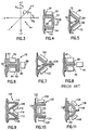
- Figs. 4-7 and Figs. 9-13 show various embodiments of a plural-bladed rail configuration, for use with active control systems, which plural-bladed rails are all distinguished from the prior art single-bladed rail, shown in Fig. 8, used in at least one prior art active system. (See U.S. Patent 4,754,849 to Ando).
- Figs. 4-7 and Figs. 9-13 more than one "blade" is used in each case to interface with two or more corresponding actuators.
- Fig. 8 in contrast, a single blade 40 is used by all three actuators 42, 44, 46. It should be understood that for all of the plural-bladed rails shown below, the associated actuators may be disposed differently than in the exact manner illustrated.
- a rectangular shape rail 48 has three blades 50, 52, 54 for serving as ferromagnetic paths or masses for three separate electromagnetic actuators 56, 58, 60 respectively.
- the actuator 58 could be positioned between the blade 52 and the hoistway wall instead, to save space and make the arrangement more compact.
- a two-bladed rail 62 having a V-shape comprising a blade 64 and a blade 66.
- a triangle-shaped configuration was previously disclosed for a passive system by Charles R. Otis in U.S. Patent 134,698.
- plural blades may be used in an active system, e.g., the blade 64 serves as a ferromagnetic mass for electromagnetic actuator 68 while blade 66 serves a similar function for actuator 70.
- the rail 62 may have footings 72, 74 for easily attaching the rail to a hoistway-way wall 76.
- the rail 62 may be formed in a full triangular cross-section with or without footings (not shown).
- the three-bladed embodiment may comprise a four-blade box-shaped rail without footings.
- the actuator 70 could be positioned opposite actuator 68, on the other side of blade 64 and blade 66 could be used as an engagement projection for a safety brake (not shown).
- FIG. 6 an I-beam 78 approach is used.
- a blade 80 is used by a pair of opposed electromagnetic actuators 82, 84 while a second blade 86 is used by a third actuator 88.
- a third blade 90 is not used as a ferromagnetic mass or path by any actuator but may be used to attach the other two blades to a hoistway wall 92.
- Fig. 7 illustrates a variation of the two-bladed V-shaped rail 62 of Fig. 5.
- Rail 94 comprises a pair of blades 96, 98 for interfacing with respective actuators 100, 102.
- the rail also includes a projecting blade 104 which may be used as a convenient handle, upon which to engage a safety brake (not shown).
- Fig. 9 shows an inverted V-shaped rail 106 having a blade 108 for interacting with an electromagnetic coil 110 and a blade 112 for a coil 114. Blades 116, 118 provide structural strength.
- Fig. 10 shows a C-shaped rail 120 having a blade 122 and a blade 124 for providing a ferromagnetic path for coils 126, 128, respectively.
- a coil 130 uses a blade 132 as its ferromagnetic mass. Blade 132 may also be used to attach rail 120 to a hoistway wall 134.
- Fig. 11 illustrates a rail 136 mounted on a hoistway wall using a facing pedestal 140.
- the rail 136 comprises a curved section 142 which, in effect, comprises two "blades", one on either side of a projecting blade 144 for safety brake purposes.
- One side of the curved section is used for interacting with a coil 146 while the other is used for interacting with a coil 148.
- Fig. 12 is an illustration of a rail 150 attached to hoistway wall 152 by means of a footing 154.
- the active part of the rail 150 comprises a circular rail 156 which in effect comprises two half-circles on either side of a projection 158.
- Coils 160, 162 used the respective halves of the circle 156 as ferromagnetic masses.
- rail 150 is, in effect, a two-bladed rail.
- Fig. 13 is an illustration of a rail 164 mounted on a hoistway wall 166 by means of footings 168, 170.
- a curved section 172 is, in effect, split into two sections on either side of a projection 174. Each section is utilized by an actuator, i.e., actuator 176, 178 respectively.
- the rail 164 is similar in concept to rail 136 Fig. 11 except it has an "omega" shape rather than a "D" shape.
- the rail 94 in Fig. 7 is the preferred embodiment for enabling the utilization of only eight electromagnets as shown below in connection with stabilization in the horizontal plane and about three axes of rotation.
- Fig. 14D is a top view of the pendulum car of Fig. 14B looking down from the bottom surface of the platform 10b of an actuator arrangement in the space between the car frame's floor and the underside of the suspended cab.
- the actuators shown in Fig. 14D are of the electromagnetic type to be described in detail below.
- the orientation of the platform 10b is the same as is shown in Fig. 14A, and the same coordinate system applies.
- the actuator 242 produces forces along the X-axis while the actuators 240, 244 produce forces along axes parallel to the Y-axis.
- Each of the actuators 240, 242, 244 has a separate control loop which is independent of the others at least in the sense of not depending on sensors in any other axis. It will, of course, be understood that the various axes of control are mechanically coupled.
- a preferred embodiment of the present invention may be utilized for increasing ride comfort in an elevator car or cab.
- the preferred embodiment of the present invention was in part described first for a cab and will now be described for a car. Again, it will be apparent that the same approach is used for both the car and cab, differing in detail only to the extent necessary to account for the fact that the actuators for a car act against a rail on a hoistway wall while the actuators for a cab act on a frame as shown in Fig. 14C.
- a suspended or supported car 250 is presented in a plan view which shows the car at rest.
- a pair of reaction planes perpendicular to the car 250 floor which intersect one another along a vertical car centerline which perpendicularly intersects the center of the square.
- the reaction planes may or may not intersect the floor along the floor's diagonals.
- one way to view the preferred embodiment of the invention is to think of the control system as causing the elevator car's centerline to remain coincident with an imaginary reference line up the center of the hoistway without the suspended or supported car rotating about the coincident car and hoistway centerlines.
- car-mounted accelerometers 252, 254, 256 (analogous to sensors 16b, 16a, 16c, respectively, of Fig. 2) which together are used to sense accelerations manifesting small translational deviations of the car's centerline from the hoistway's centerline and by further sensing accelerations manifesting small rotations of the car about the hoistway centerline and by the selective use of actuators 258, 260, 262, 264 exerting forces perpendicular to the reaction planes to maintain the centerlines' desired coincidence with no rotation.
- V-shaped rails 267, 268, similar to the rail pictured in Figs. 5 and 7, or similar, such as that of C. R. Otis, affixed to opposite hoistway walls 267a, 268a provide ferromagnetic reaction plates 270, 272, 274, 276.
- Four electromagnet cores 280, 282, 284, 286 with associated coils may be attached to the sides, near the bottom, of a suspended or supported platform so that each faces one of the reaction plates. Attractive forces generated by the control system by means of the four electromagnet core-coils are exerted in such a way as to separate or bring closer the core-coils from their associated reaction plates.
- the positioning of the core-coils with respect to the reaction planes can of course vary, as with the cab example, except in this case most especially according to the selected rail shape.
- a digital signal processor embodiment which may comprise an Input/Output (I/O) device 280 which may include an Analog-to-Digital (A/D) converter (not shown) responsive to an analog signal provided by sensor 16, which may be accelerometers 204, 206, 208 as shown in Fig. 14C or accelerometers 252, 254, 256 shown in Fig. 15.
- the I/O device 280 may further comprise a Digital-to-Analog (D/A) converter (not shown) for providing force command signals on line 22 to an analog actuator 24 which may instead comprise the actuators 210, 212, 214, 216 of Fig.
- D/A Digital-to-Analog
- a control, data and address bus 282 interconnecting a Central Processing Unit (CPU) 284, a Random Access Memory (RAM) 286 and a Read Only Memory (ROM) 288.
- the CPU executes a step-by-step program resident in the ROM, stores input signals having magnitudes indicative of the value of the sensed parameter as manifested on the line 18 in the RAM, as well as signals having magnitudes representing the results of intermediate calculations and output signals having magnitudes indicative of the value of the parameter to be controlled as manifested in the output signal on line 22.
- an input step 302 is executed in which the magnitude(s) of the signal(s) on line 18 is (are) acquired by the I/O unit 280.
- signals A x1 , A x2 and A y provided, respectively, by accelerometers 204, 208, 206 of Fig.
- step 304 can be used in a step 304 to compute the magnitude of a positive or negative A x signal, or both can be used as a check against one another, used to provide an average, or used in some such similar redundancy technique.
- steps 302, 304 can be combined into a single sensing step if a rotation sensor is provided along with two translational [x and y] sensors).
- a ⁇ may be made in step 304.
- the magnitude of the signal A ⁇ will depend on the degree to which the magnitude of the signals from accelerometers 204, 208 (or, 252, 256) differ. The sign of their summation determines the rotational direction.
- the values of A x , A y and A ⁇ are stored temporarily in RAM 286.
- step 310 After making the necessary computations and providing the required counterforce command signals the program is exited in a step 310.
- additional steps are also taken in order to superimpose a system for ensuring against imperfectly levelled accelerometers and also against a changing offset in the accelerometers.
- Accelerometers have two major errors: (i) offset drift and (ii) pickup of unwanted gravity components due to not being perfectly level; also present, but not as significant, are (iii) linearity errors.
- a nonlevel accelerometer will sense accelerations due to gravity in proportion to the sine of the angle it makes with true vertical. Correction for nonlinearity is not usually important in embodiments of this invention but may be corrected for, if desired (see Fig. 23).
- nonlinearity may be corrected at each stage of sensed acceleration by consulting a lookup table which is used to supply a corrective factor. If offset were constant over time it could be corrected for straightforwardly with a constant correction factor. But, since offset can change over time due to temperature, aging, etc., corrections should be made in a dynamic manner. Offset and changing offset, as well as accelerations due to gravity, can be corrected by providing a relatively slower acting feedback control system for controlling the position of the car or cab with respect to the hoistway centerline. This may be done by recognizing that the average lateral acceleration must be zero (or the car or cab would travelling off into space). The slow acting loop offsets the average accelerometer output signal. Averaging may be accomplished, e.g., using an analog low-pass filter or a digital filter.
- a single axis of control such as the x-axis shown in Fig. 2
- the theory of operation of such a system for controlling the cab or car with both acceleration and position sensors is shown in Fig. 18.
- the system in elementary form comprises the car or cab mass as illustrated by a block 320.
- the car or cab mass is acted upon by a force on a line 322 which causes an acceleration as illustrated by a line 324.
- a disturbing force is shown schematically as a signal on a line 326 summed in a "summer" 328 (an abstract way of representing that the disturbing force is physically opposed by the counteracting force) with a counterforce signal on a line 330 provided in proportion (K a ) to the acceleration (A) shown on the line 324 as sensed by an accelerometer 332 which provides a sensed acceleration signal on a line 334 to a summer 336.
- the scale factor (K a ) of the accelerometer is (volt/m 2 /s).
- the acceleration on line 324 is produced by the disturbing force on line 326 interacting with the mass of the suspended or supported car or cab according to the relation F/M as suggested in block 332, where F is the disturbing force and M is the mass of the car or cab.
- the summer 328 represents the summation of the disturbing force on line 326 and the counterforce on line 330 to provide a net force on a line 322 acting on the mass 320.
- the summer 336 may provide a signal on a line 338 to a force generator 340 which may have a transfer characteristic of 1.0 Newton/volt.
- the summer 336 serves to connect an inner acceleration loop signal on line 334 with the outer acceleration and position loop signals to be described below prior to introduction on the line 338 into the force generator 340.
- the inner acceleration loop comprising elements 320, 332, 340 and the associated summers forms the primary control loop used for "mass augmentation" as defined herein.
- a position transducer that gives car position is represented abstractly by an integrator block 342 and an integrator block 344.
- the integrator 342 provides a velocity signal on a line 346 to the integrator 344 which in turn provides a position signal on a line 348.
- the cab position signal on line 348 is compared in a summer 350 with a reference signal on a line 352.
- the signal on the line 352 would ordinarily be a fixed DC level scaled to represent, e.g., the x-position (in the cab coordinate system 218 of Fig. 14C or in the car coordinate system 266 of Fig. 15) of a selected referent such as the hoistway centerline (which will be substantially coincident with true vertical, i.e., a line along which the earth's gravity will act).
- a selected referent such as the hoistway centerline (which will be substantially coincident with true vertical, i.e., a line along which the earth's gravity will act).
- This entire process is carried out in practice by use of a position sensor that gives the relative position between the cab and car frame.
- the summer 350 provides a signal on a line 354 which represents the relative position of the cab with respect to the frame and may be characterized as the relative position signal or the position error signal.
- a low-pass filter 358 It is provided on a line 356 to a low-pass filter 358 after being summed in a summer 360 with a signal on a line 362.
- the low-pass filter 358 provides a filtered signal on a line 364 which causes the force on the line 330 to be applied on the line 322 to the car or cab 320 until the position error signal is driven to zero or close to zero.
- a second secondary control loop may be introduced if a position signal is not conveniently available or to enhance the stability of the position correction control loop.
- the position error signal on line 354 may thus be modified in the summer 360 by being summed with the signal on line 362 which is provided by a gain block 366 which is in turn responsive to the signal on line 338 which is representative of the acceleration sensed in the primary loop.
- G 1 *G 2 could be chosen equal to nine (9) to reduce accelerometer offsets by a factor of ten (10).
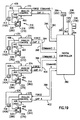
- Fig. 18 The control represented in abstracted form in Fig. 18 may be carried out in numerous different ways but a preferred approach is shown in Fig. 19.
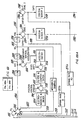
- a fast-acting analog loop for quickly counteracting disturbing forces is combined with a slower acting but more accurate digital loop for compensating for gravity components and drifts in the accelerometers.
- a plurality of such fast-acting analog loops may be embodied in analog controls 370, 372, 374, 376 as shown, one for each of the respective actuators 210 or 258, 212 or 260, 214 or 262, 216 or 264, of Figs. 14C or 15, respectively.
- a single digital controller 380 can handle the signals to be described to and from all four analog controls. Each analog control responds to a force command signal on lines 382, 384, 386, 388 from the digital controller 380.
- the force command signals will have different magnitudes depending on the translational and rotational forces to be counteracted.
- the digital controller 380 is in turn responsive to acceleration signals on lines 390, 392, 394 from the accelerometers 204 or 252, 206 or 254, 208 or 256, respectively (the accelerometers being from either Fig. 14C or 15), and to position signals on lines 396, 398, 400, 402 indicative of the size of the air gaps between the coil-cores 226 or 280, 228 or 282, 230 or 284, 232 or 286 and their respective plates 218 or 270, 220 or 272, 222 or 274, 224 or 276.
- the analog controls 370, 372, 374, 376 provide actuation signals on lines 404, 406, 408, 410 to the coils of the coil-cores 226 or 280, 228 or 282, 230 or 284, 232 or 286 for causing more or less attractive forces between the respective core-coils 226 or 289, 228 or 282, 230 or 284, 232 or 286 and their associated reaction plates.
- the return current through the coils is monitored by current monitoring devices 412 or 420, 414 or 422, 416 or 424, 418 or 426 which provide current signals on lines 428, 430, 432, 434 to the respective analog controls 370, 372, 374, 376.
- the current sensors may be, e.g., Bell IHA-150 with multiple looping of the "through" lead.
- the sensors 440 or 448, 442 or 450, 444 or 452, 446 or 452 provide sensed signals on lines 460, 462, 464, 466, respectively, to the analog controls 370, 372, 374, 376.
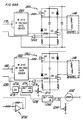
- the analog control 370 among the plurality of analog controls 370, 372, 374, 376 of Fig. 20, is shown for one embodiment in detail.
- the other analog controls 372, 374, 376 may be the same or similar.
- the force command signal on line 382 from the digital controller 380 of Fig. 19 is provided to a summer 470 where it is summed with a signal on a line 472 from a multiplier 474 configured as a squaring circuit (to linearize control) having a gain selected dimensionally to be equivalent to magnetization (amp/meter) and properly scaled to convert a signal on a line 476 indicative of flux density to one indicative of force.
- the flux density signal on line 476 is provided by a Hall cell amplifier 478 which is used to boost the level of the signal on a line 480 from the Hall cell 440 or 448.
- the summer 470 provides a force error signal on a line 484 to a proportional-integral (P-I) amplifier 486 which provides a P-I amplified signal on a line 488 to a firing angle compensator 490.
- Compensator 490 provides a firing angle signal on a line 492 which controls the firing angle of a plurality of SCRs in a controller 494 after being filtered by a filter 496 which in turn provides a filtered firing angle signal on a line 498 to the controller 494 which is more fully described as a single phase, two-quadrant, full-wave, SCR power converter. This type of converter is preferred over one-quadrant and half-wave converters. The least preferred combination would be a one-quadrant, half-wave.
- the two-quadrant, full wave converter 494 of Fig. 20 may be made up, for example, of a pair of Powerex CD4A1240 dual SCRs and a circuit configuration as shown in part Fig. 21 (not shown are RC snubbers across the SCRs) and a commercial firing board 253 such as a Phasetronics PTR1209 which is shown in Fig. 22.
- Gate signals on a plurality of lines 253a for the SCRs are provided by the firing board 253.
- the power controller 252 is powered with 120 VAC on a line 254 as is the firing board and provides the proper level of current on line 180 in response to the filtered firing angle signal on line 250.
- the signal on the line 428 from the current sensor 412 is provided to an analog multiplier/divider 504 (such as an Analog Devices AD534) which is also responsive to the flux density signal on line 476 for dividing the magnitude of the current signal on line 428 by the magnitude of the flux density signal on line 476 and multiplying the result by a proportionality factor in order to provide the signal on line 396 (back to the digital controller 380 of Fig. 19) indicative of the magnitude of a gap (g 1 ) between the face of the core of the core-coil 226 and the plate 218.
- an analog multiplier/divider 504 such as an Analog Devices AD534
- the digital controller 380 is responsive to the gap signals on the lines 396, 398, 400, 402, as well as the acceleration signals on lines 390, 392, 394, for carrying out, in conjunction with analog controls of the type shown in Fig. 20, the control functions of Fig. 18. Instead of generating force signals on the lines 382, 384, 386, 388 in exactly the same manner as previously disclosed in connection with Figs.
- Such corrective force signals may be generated, for example, by first resolving the sensed position signals into components along the axes of the Cartesian coordinate system 218 or 266 of Fig.
- P x+ (P 1 + P 3 )/(2KCS)
- P x- (P 2 + P 4 )/(2KCS)
- P y+ (P 1 + P 2 )/(2KCS)
- P y- (P 3 + P 4 )/(2KCS)
- P ⁇ + (P 2 + P 3 )/2
- P ⁇ - (P 1 + P 4 )/2
- P x+ or P x- depending on which quantity is smaller. (Note: For large gaps, i.e., for large P x+ or P x- , the value is likely to be inaccurate and may be discarded).
- the resultant components are used to determine position-control force components F px , F py , F p ⁇ as illustrated in Fig. 18 on a single-axis basis ("P" stands for position feedback).
- P x for example on line 348, is compared to a reference on line 352 to generate an x-position error signal on line 354. This in turn is passed through a low-pass such as filter 358. This provides an F px signal.
- the gap signals on lines 396, 398, 400, 402 could be provided by a simple position sensor only.
- an additional advantage of our invention is that the electromagnets may be used to control the position of the car or cab at stops, e.g., to bring the suspended or supported car or cab to rest with respect to the frame while on- and off-loading passengers.
- the signal processor of Fig. 16, the digital controller 380 of Fig. 19 or an additional signal processor may handle additional control functions such as the starting and stopping of cars and the dispatching of cars.
- the processor 20 of Fig. 16 may receive a sensed signal on line 18 or an algorithmically determined but similar signal indicating the car is vertically at rest and will then provide a signal on line 22 to control the position of the suspended or supported car or cab. For, example, if the cab platform 200 of Fig.
- the signal processor 20 of Fig. 16 may be programmed to provide force command signals to actuators 210, 214 in order to provide the attractive forces needed to force the suspended cab up against, e.g., stops 702, 704a mounted in the car frame 202 so as to push the cab sill into position at rest with respect to, and in close alignment with the hoistway entrance sill 700 after the signal processor 20 causes the frame 202 to come to rest.
- the stops may be part of the actuators themselves, for example, mounted on the top faces of the legs 304, 306 of the core shown in Fig.
- 16 may be programmed to provide force command signals to actuators 212, 216 in order to provide the attractive forces needed to force the suspended cab up against, e.g., stops 513, 513a mounted in the car frame 202 so as to push the cab sill into position at rest with respect to, and in close alignment with the hoistway entrance sill 514 after the frame 202 comes to rest.
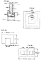
- An electromagnetic actuator such as described previously may be constructed in a U-shape as shown in Figs. 29 and 30.
- double coils 300, 302 are shown which fit over legs 304, 306, respectively, as shown in Fig. 30.
- the coils 300, 302 constitute a continuous winding and are shown in isometric section in Fig. 30.
- Coil 300 and coil 302 may each, for example be wound with 936 turns of #11 AWG magnet wire at a 0.500 packing factor.
- the U-shaped core may, for example, be of interleaved construction, 29 GA M6 laminations made of 3.81cm strip stock, vacuum impregnated. The dimensions shown in Fig.
- the resistance would be 6.7 ohms and the inductance 213mH. Such weighs 22.2kg and is capable of exerting 578 Newtons.
- the time to develop half force would of course be half the time.
- An accuracy in the gap signal of 10% of full scale can be tolerated.
- the maximum power is 500 Watts at a maximum allowed 20 mm gap.
- the average power can be expected to be approximately 125 Watts.
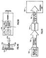
- Fig. 31 shows a single-axis lateral vibration stabilization system for use in a system such as shown in Fig. 14D.
- the concept is the same as shown in Figs. 18, 24, and 25.
- the implementation to be described will be analog but it will be understood that it can be carried out digitally as well.
- a plate 352 is attached, without limitation, to the suspended cab while a pair of electromagnetic actuators 354, 356 are attached to the elevator car frame.
- the accelerometer 358 senses accelerations of the suspended cab and provides a sensed signal on a line 360 to an amplifier 362 which in turn provides an amplified sensed acceleration signal on a line 364 to a summing junction 366 where it is "summed" with a disturbing force signal on a line 368 and a position loop corrective or "error" signal on a line 370.
- a resultant summed signal on a line 372 is provided to a pair of rectifiers 374, 376 which are shown respectively in Figs. 33 and 34.
- the rectifier 374 provides a signal on a line 378 to a signal inverter 380, which is also shown in Fig.
- the rectifier 376 provides a signal on a line 384 which may be characterized as a positive control signal.
- Both the signals on lines 382 and 384 are summed in respective summing junctions 388, 390 with a bias signal on a line 392. These provide biased control signals on lines 394, 396 to electromagnetic actuator controllers 398, 400, respectively.
- the controllers 398, 400 are or may be similar to those shown in Fig. 20.
- Fig. 32 shows the composite resultant force (in dashed lines) of the two forces on either side of the reaction plate 352 (in solid lines) vs. the control signal (FC) for the system of Fig. 31.
- This technique is used to prevent discontinuities in control about the zero position point. Without bias, turn-off of one magnet and turn-on of the other could occur at the same time.
- the illustrated technique, using bias, results in reduced control gain at or near zero force. The advantage is that only one magnet goes from on to off or vice versa at any given time. Bias helps assure that "dither" of the cab will not occur during periods requiring little or no correction.
- the signals on lines 394 and 396 may be thought of as force command signals similar to the force command signal on line 382 in Fig. 20.
- the controls 398, 400 provide actuator output signals on lines 402, 404 to actuators 356, 354, respectively, in a manner similar to the output signal on line 500 in Fig. 20.
- each control 398, 400 provides position output signals 406, 408 corresponding to the gap signal on line 396 in Fig. 20.
- both position signals on line 406, 408 and the corresponding, but opposite sided, rectification signal on lines 384, 382 are provided to a pair of FC-controlled clamp circuits 410, 412 for the purpose of selection of the valid position signal (both P + and P - provide position signals; however, only the position signal corresponding to the driven force generator is valid).
- the outputs of the clamp circuits are provided to a summing junction 414 for the purpose of obtaining the valid position signal. Also provided to the summing junction 414 is an attenuated acceleration signal on a line 415 from an attenuator 415a responsive to the amplified acceleration signal on line 364.
- the output of the summing junction is a composite position and acceleration signal on a line 416 which is provided to a low pass filter 418 which has a time constant in the range of 1 to 10 seconds.
- the low pass filter 418 in turn provides the corrective signal on the line 370 to summing junction 366, previously described.
- Three single-axis controls such as just described can be used for the actuators of Fig. 14D in lieu of the combined three-axis schemes described previously in connection with Figs. 14C and 15.
- the three-axis scheme has many advantages. Among these are stabilization of all sensitive axes using a minimum number of electromagnets.
- a plus or minus 15 mm gap variation for a single-axis or multiple-single-axis system reduces to a plus or minus 10.5 mm variation in a three-axis scheme.
- Fig. 36A is another block diagram of a specific implementation of an active suspension system, according to the present invention.
- one axis e.g., side-to-side along the X-axis passing through the car's vertical centerline
- the other axes e.g., front-to-back along two axes parallel to the Z-axis and lying, e.g., equidistantly from and on opposite sides of the vertical centerline
- An acceleration reference signal may be input on a line 100 and may be set to zero.
- the summing junction 109 is shown responsive to the compensator output and to disturbances of the indirect type, such as rail disturbances, as provided by the system dynamics 109a and of the direct type of disturbance, such as wind forces, as provided by system dynamics 109b.
- the first term covers DC washout
- the second is for pendulum compensation
- the third term is for control.
- the feedback compensator in each axis processes the car acceleration error signal for that axis to generate actuator commands.
- a force command signal is provided on a line 110.
- These compensators can be viewed as dynamic filters whose properties (gain and phase vs. frequency) are designed to meet elevator system requirements.
- the design of C(s) can be recast into design requirements on the overall loop gain, labelled L(s), which is the product of C(s) and the plant dynamics as illustrated in a block 108, labelled G(s).
- the force command signal on the line 110 is provided to plant dynamics 108. As shown in Fig.
- the loop gain is made to be greater than one, i.e., in a region about a frequency ⁇ 0 .
- the loop gain is "rolled off” to meet stability robustness requirements.
- the loop gain is "washed-out” to reduce the effects of sensor noise and drift.
- Figs. 37A and 38B are actually a plot of the designed open loop transfer function for an active system, L(s), that resulted from that analysis.
- a plot of the feedback compensator gain and phase angle are shown, respectively, in Figs. 38A and 38B for this particular design.
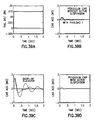
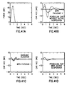
- Figs. 39 through 41 summarize the results of a simulation study of the performance of the resulting active suspension system.
- the upper lefthand plots in each of these figures (labelled (a)) is the particular disturbing input (direct car force or rail profile).
- the remaining plots on each of these figures show the car acceleration response for three configurations: (1) pendulum car (upper-right, labelled (b)), (2) conventional car (lower-left, labelled (c)), and (3) active suspension using the control design of Figs. 36A, 36B, 37A, 37B, 38A, and 38B (lower-right, labelled (d)). It can be seen that this system reduces the levels of cab platform acceleration relative to conventional systems and even those of the pendulum car without active control.
- Fig. 39 is the predicted response to butt joint misalignment.
- Fig. 40 is the predicted response to rail waviness.
- Fig. 41 is the predicted response to car force disturbance.
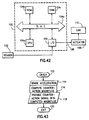
- the feedback compensator 106 of Fig. 36A was implemented using a digital computer 100 as shown in Fig. 42.
- Sensor 102 data is provided on a line 103 into a 12-bit A/D converter (not shown) to be processed after passing through an Input/Output Port 104.
- a digital form of the feedback compensator 106 was utilized to produce a command signal on a line 106 to an actuator 108 capable of exerting forces on a car 110.
- the signal processor 100 comprises a central processing unit 104a, a read-only memory 104b, a random access memory 104c, all communicating by means of data, address, and control bus 104d.
- Fig. 43 is an illustration of a series of steps which may be carried out by the signal processor 100 of Fig. 42.
- acceleration is sensed in a step 114 by means of an accelerometer 102.
- the processor then computes the magnitude of a counteractive force by implementing the dynamic compensation 106.
- a step 118 is next executed in which the signal processor 100 provides the counteraction signal on line 106 which may be a counterforce signal, such as the signal on line 106 and as computed in step 116.
- An exit is then made in a step 120.
- Fig. 44 shows the results of a test to evaluate the effectiveness of the active system in mitigating direct car forces.
- the plot shows the ratio of the measured car acceleration to the magnitude of the sinusoidal input force over a sweep of frequencies.
- the top curve is the response of the pendulum car system without active suspension control.
- the bottom curve response of the active suspension system verifies the expected 80%-90% reduction.
- Fig. 45 shows a comparison of the predicted time response (via simulation in Figs. 45B and D) and the achieved (experimental) time response (Figs. 45A and C) for direct car force mitigation.
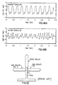
- Fig. 46 illustrates the response of the system to a rail irregularity as simulated on a test bed with a rotating imbalance.
- Fig. 46A shows the unaugmented pendulum car response to a 3 Hz input frequency.
- Fig. 46B is the response of the active suspension system. It can be seen that the magnitude of the car acceleration has been decreased.
- the active suspension system improves the ride quality using car acceleration as the metric of performance in the presence of both rail-induced disturbances and direct car forces.
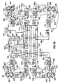
- the actuator command signal on line 106 as shown in Fig. 42 may be a force command signal, as previously explained, and as shown in more detail in Fig. 47, as being applied to a particular actuator which may include, for example, the core-coils and ferromagnetic plates of Figs. 29 and 30.
- the force command signal on line 106 from the signal processor 100 of Fig. 42 is provided to a PWM amplifier which may be made by Copley Controls Corp. of 375 Elliot Street, Newton, Massachusetts, U.S.A., and called a "Class B PWM Servo Amplifier Model 218A" as described in published specification sheet entitled "Model 215A, 218 Servo Amplifier”.
- the PWM Amplifier 150 is responsive also to a force feedback signal on a line 152.
- the PWM amplifier serves as an electronic double pole-double throw switch to apply a selected voltage to lines 154,156 with a polarity reversal at a selected duty cycle.
- a pair of steering diodes 158, 160 steer the output current on either line 154 or 156 into the proper coil of the corresponding magnet 130, 132.
- the ferromagnetic mass 134 or the electromagnets will be erected on the base of the frame 26 while the other element is erected on the bottom surface of the platform 14.
- the electromagnets 130, 132 are erected on the bottom of the frame 26 while the ferromagnetic mass 134 is fixedly attached in a hanging down fashion to the bottom of the platform 10b. This is the case for the other actuators 240, 244 of Fig. 14D as well.
- Hall cells 170, 172 may be placed in the magnetic circuit path so as to sense magnetic flux in the gap between the ferromagnetic plate 134 and the respective cores of core-coils 130, 132.
- the Hall cells 170, 172 provide sensed flux signals on lines 174, 176, respectively, to a device 182, which may be a multiplying IC such as an AD 534, which squares the magnitudes of the flux signals on lines 174, 176 and provides a difference signal indicative of the difference therebetween as the force feedback on line 152.
- Figs. 36A and 36B may be carried out in numerous different ways, including a wholly digital approach similar to that of Fig. 42, but a preferred approach is shown in Fig. 48.
- the embodiment of Fig. 48 includes two such independent control systems, each for controlling actuators on opposite sides of the car, identical or similar to that illustrated in Fig. 15, one system for the floor or near the bottom of the car, and the other system for the ceiling or near the top of the car.
- Fig. 36A the fundamental principal of active control can be carried out in a plurality of coordinated single axis controls as previously suggested.
- the control represented in abstracted single-axis form in Fig. 36A may be carried out in numerous different ways but a preferred approach is to extend the same principles as disclosed in the three-axis control of Fig. 15 to achieve the five-axis control shown in Fig. 48.
- Fig. 48 may be extended to a pendulum or supported cab, as will be apparent to one skilled in the art.
- fast-acting analog loops for quickly counteracting disturbing forces are combined with slower acting but more accurate digital loops for compensating for gravity components and drifts in the accelerometers.
- a plurality of such fast-acting analog loops may be embodied in analog controls 500, 502, 504, 506, for independently controlling the top of the car, and analog controls 508, 510, 512, 514 for independently controlling the floor of the car as shown, one for each of eight actuators 516, 518, 520, 522, and 524, 526, 528, 530, respectively.
- a single digital controller 532 can handle the signals to be described to and from all eight analog controls.
- Each analog control responds to a force command signal on lines 534, 536, 538, 540, and 542, 544, 546, 548 from the digital controller 532.
- the force command signals will have different magnitudes depending on the translational and rotational forces to be counteracted.
- the digital controller 532 is in turn responsive to acceleration signals on lines 552, 558, 559, and 550, 554, 556 from the accelerometers 562, 568, 569, and 560, 564, 566, respectively, and to position signals on lines 570, 572, 574, 576, and 578, 580, 582, 584 indicative of the size of the air gaps between the cores of actuators 516, 518, 520, 522, and 524, 526, 528, 530 and their respective facing ferromagnetic blades.
- the respective analog controls 500, 502, 504, 506, and 508, 510, 512, 514 provide actuation signals on lines 586, 588, 590, 592, and 594, 596, 598, 600 to the coils of the actuators 516, 518, 520, 522, and 524, 526, 528, 530 for causing more or less attractive forces between the respective actuator cores and their associated ferromagnetic blades.
- the return current through the coils is monitored by current monitoring devices 602, 604, 606, 608, and 610, 612, 614, 616 which provide current signals on lines 618, 620, 622, 624, and 626, 628, 630, 632 to the respective analog controls 500, 502, 504, 506, and 508, 510, 512, 514.
- the current sensors may be, e.g., Bell IHA-150.
- a plurality of sensors 634, 636, 638, 640, and 642, 644, 646, 648 which may be Hall cells (e.g., of the type Bell GH-600), are respectively associated with each actuator core for the purpose of providing an indication of the flux density or magnetic induction (volt-sec/m 2 ) in the gap, i.e., between the faces of the cores and the associated blades or, otherwise stated, the flux density in the air gaps therebetween.
- the sensors 634, 636, 638, 640, and 642, 644, 646, 648 provide sensed signals on lines 650, 652, 654, 656, and 658, 660, 662, 664, respectively, to the analog controls 500, 502, 504, 506, and 508, 510, 512, 514.
- the analog control 500 among the plurality of analog controls of Fig. 48, is similar or identical to that shown in greater detail in Fig. 20.
- the other analog controls may be the same or similar.
- the digital controller 532 is responsive to the gap signals on the lines 570, 572, 574, 576 and 578, 580, 582, 284, as well as the acceleration signals on lines 552, 558, 559, and 550, 554, 556, for carrying out, in conjunction with an analog control, such as shown in Fig. 20, the single axis control functions of Fig. 36A in five axes, i.e., translations along two horizontal axes in both the floor and roof, rotations about the same two axes in both the floor and roof, and rotations of both floor and roof about a vertical axis.
- the car or cab as a solid or stiff cube having a three axis Cartesian coordinate system with its origin in the center and subject to translations along, and rotations about, the horizontal axes and rotations about the vertical axis.
- P x+ or P x- depending on which quantity is smaller. (Note: For large gaps, i.e., for large P x+ or P x- , the value is likely to be inaccurate and may be discarded).
- the resultant components are used to determine position-control force components F px , F py , F p ⁇ as illustrated in Fig. 48 on a single-axis basis ("P" stands for position feedback).
- P x for example on line 348, is compared to a reference on line 352 to generate an x-position error signal on line 354. This in turn is passed through a low-pass such as filter 358. This provides an F px signal.
- the electromagnets may be used to control the position of the car or cab at stops, e.g., to bring the suspended or supported car or cab to rest with respect to the frame while on- and off-loading passengers.
- the signal processor of Fig. 16 the digital controllers 380, 532 of Figs. 19 and 48 or an additional signal processor may handle additional control functions such as the starting and stopping of cars and the dispatching of cars. In the case of stopping at a floor, it may receive a sensed signal on line 18 or an algorithmically determined but similar signal indicating the car is at rest and will then provide a signal on line 22 to control the position of the suspended or supported car or cab.
- the signal processor 20 of Fig. 16 may be programmed to provide force command signals to actuators 210, 214 in order to provide the attractive forces needed to force the suspended cab up against, e.g., stops 702, 704 mounted in the car frame 202 so as to push the cab sill into position at rest with respect to, and in close alignment with the hoistway entrance sill after the frame 202 comes to rest.
- a stop signal is provided in a step 720 from means 722 (which may be incorporated in the processor 532 in an additional role of controlling a car or group of cars) for indicating the car frame has come to rest, providing a stop or stop command signal and, in response thereto, an actuator 724 (which may be actuators 210 and 214 acting in concert) provides an actuating signal as shown in a step 726 for causing a suspended cab 728 (which may be cab 200) to come to rest with respect to the car frame (which may be frame 202) such that the cab sill is adjacent to the hall sill and motionless with respect thereto.
- a suspended cab 728 which may be cab 200
- a similar set of stops 730, 732 can be provided at each landing for the car of Fig. 15 to be pushed against and a similar procedure as that of Fig. 51 can be followed.
- a preferred embodiment of the invention utilizes electromagnetic, noncontact type actuators and, in particular, in connection with a suspended or supported car uses electromagnetic actuators such as are shown in Fig. 15 in conjunction with hoistway rails
- electromagnetic actuators such as are shown in Fig. 15 in conjunction with hoistway rails
- contact-type, active actuators For example, Fig. 49 shows a standard rail 750 attached to a hoistway wall 752 having three contact-type actuators having wheels 754, 756, 758 in contact therewith for guiding an elevator car.
- Fig. 50 shows one of the actuators 760 in detail having wheel 754 associated therewith actuated with a solenoid 762 having a coil 764 similar to a coil which would be used in an electromagnetic actuator of the previously disclosed, contact-less type.
- the other wheels 756, 758 would have similar solenoids associated therewith.
- Fig. 49 it is, of course, standard practice to provide one or more guide rails for each elevator car in an elevator system to guide and stabilize the car as it moves up and down between floors.
- wheels mounted by means of springs on the car typically ride on the rail for guidance and motion control of the car.
- the guide rails Since an elevator car needs to be guided to remain along the specified path of travel, the guide rails have to withstand all the forces that may result from, for example, normal elevator operation and emergency stops.
- the guide rail can be of any shape capable of constraining the elevator in its path. The problem then becomes finding the most economical shape.
- an improved guide rail design is used, which can achieve at least the same amount of strength with relatively less weight or at least a higher strength to weight ratio than that of the standard inverted "T" section rail, while still achieving a comparable (if not equal or greater) amount of guidance and stabilization control as achieved by the standard, established design.
- the improved design is particularly suited to the use suggested in Figs. 5 and 7.
- FIG. 1 Another configuration known is a round tubular shape, similar to a pipe, but this design has generally been limited to cases where emergency stopping by safety brakes is not necessary.
- Other shapes considered for guide rails have included, for further example, a "hat” shape somewhat like an inverted, flat bottomed, inverted “U” with end tabs, a “bell” shape, and a rectangular tubular shape.
- the preferred embodiment of the longitudinally extended guide rail 1 includes a base or blade section 2 with two, preferably integrally formed, diverging blades or legs 3 with the legs terminating in end tab portions 4.
- the end tab portions are used for mounting and fastening the guide rail 1 to the building structure.
- the two diverging legs form between them a void 3A.
- FIG. 53 three guide wheels 5A, 5B and 5C interface with the base or blade section 2, in similar fashion and configuration as they did with the "T" shape guide rail, as illustrated in Fig. 52.
- the two opposed wheels 5A and 5B bear against the opposed sides of the blade section 2, while the intermediate wheel 5C bears against the distal tip of the blade section.
- the Y-shape is slightly better in section properties than the corresponding T-shape and yet weighs eighteen (18%) percent less.
- the overall dimensions of both shapes are almost the same (Table 1), namely, twelve and seven-tenths centimeters by eight and 89/100 centimeters (12.7 cm x 8.89 cm) for the T-shape and thirteen and 02/100 centimeters by nine and 53/100 centimeters (3.02 cm x 9.53 cm) for the Y-shape.
- the Y-shape rails can be rolled in-steel mills in pieces of desired length, for example, four and 88/100 meters (4.88 m) each. Machining of the blades can be done easily in milling or planing machines, in similar fashion to that done for the "T" rail. Cutting of mating slots at the end and drilling of holes in the "Y" shaped guide rail would typically be included and are made as easy as in the "T" shaped rail.
- Figs. 56 and 57 are still other illustrations of an embodiment of means for carrying out the present invention, in the form of an "active" roller guide, showing details of a roller cluster 1000.
- one of the rollers (side-to-side) is elevated with respect to the other two, it will be appreciated that the roller cluster 1000 is a relatively conventional arrangement of rollers on a rail 1001.
- the cluster 1000 includes a side-to-side guide roller 1002 and front-to-back guide rollers 1004 and 1006.
- the roller cluster 1000 is mounted on a base plate 1008 which is fixed to an elevator cab frame crosshead (not shown).
- the guide rail 1001 will be a conventional, generally T-shaped structure having basal flanges 1010 for securement to the hoistway walls 1012, and a blade 1014 which projects into the hoistway toward the rollers 1002, 1004 and 1006.
- the blade 1014 has a distal face 1016 which is engaged by the side-to-side roller 1002, and side faces 1018 which are engaged by the front-to-back rollers 1004 and 1006.
- the guide rail blade 1014 extends through a slot 1020 in the roller cluster base plate 1008 so that the rollers 1002, 1004 and 1006 can engage the blade 1014.
- the side-to-side roller 1002 is journaled on a link 1022 which is pivotally mounted on a pedestal 1024 via a pivot pin 1026.
- the pedestal 1024 is secured to the base plate 1008.
- the link 1022 includes a cup 1028 which receives one end of a coil spring 1030.
- the other end of the spring 1030 is engaged by a spring guide 1032 which is connected to the end of a telescoping ball screw adjustment device 1034 by a bolt 1036.
- the adjuster 1034 can be extended or retracted to vary the force exerted on the link 1022, and thus on the roller 1002, by the spring 1030.
- the ball screw device 1034 is mounted on a clevis 1038 bolted to a platform 1040 which in turn is secured to the base plate 1008 by brackets 1042 and 1044.
- the use of the platform 1040 and brackets 1042 and 1044 allows the assembly to be retrofitted on a conventional roller guide assembly directly on the existing base plate 1008.
- the ball screw device 1034 is powered by an electric motor 1046.
- a ball screw actuator suitable for use in connection with this invention can be obtained from Motion Systems Corporation, of Box 11, Shrewsbury, New Jersey 07702.
- the actuator motor 1046 can be an AC or a DC motor, both of which are available from Motion Systems Corporation.
- the Motion systems Model 85151/85152 actuator has been found to be particularly suitable for use in this invention.
- a position sensor 1049 such as a potentiometer or optical sensor may be attached to the car frame by attachment to the reducer 1048 to a lip on the rear of the spring holder 1032 in order to measure the linear extension of the screw.
- a position sensor 1049 such as a potentiometer or optical sensor may be attached to the car frame by attachment to the reducer 1048 to a lip on the rear of the spring holder 1032 in order to measure the linear extension of the screw.
- other position sensors may be used as well.
- the guide roller 1002 is journaled on an axle 1050 which is mounted in an adjustable receptor 1052 in the upper end of the link 1022.
- a pivot stop 1054 is mounted on a threaded rod 1056 which extends through a passage 1058 in the upper end 1060 of the pedestal 1024.
- the rod 1056 is screwed into a bore 1062 in the link 1022.
- the stop 1054 is operable by selective engagement with the pedestal 1024 to limit the extent of movement of the link 1022 in the counter-clockwise direction about the pin 1026, and therefore limit the extent of movement of the roller 1002 in a direction away from the rail, which direction is indicated by an arrow D.
- the pedestal 1024 is formed with a well 1064 containing a magnetic button 1066 which contains a rare earth compound.
- Samarium cobalt is a rare earth compound which may be used in the magnetic button 1066.
- a steel tube 1068 which contains a Hall effect detector (not shown) proximate its end 1070 is mounted in a passage which extends through the link 1022.
- the magnetic button 1066 and the Hall effect detector form a proximity sensor which is operably connected to a switch controlling power to the electric motor 1046.
- the proximity sensor detects the spacing between the magnetic button 1066 and the steel tube 1068, which distance mirrors the distance between the pivot stop 1054 and the pedestal 1024.
- the pivot stop 1054 moves toward the pedestal 1024.
- the detector produces a signal proportional to the size of the gap between the detector and the magnetic button 1066, which signal is used to control the electric motor 1046 whereby the ball screw 1034 jack is caused to move the link 1022 and roller 1002 toward or away from the rail, as the case may be.
- the stop 1054 may be prevented from contacting or at least prevented from establishing prolonged contact with the pedestal 1024. This ensures that roller 1002 will continue to be damped by the spring 1030 and will not be grounded to the base plate 1008 by the stop 1054 and pedestal 1024. Side-to-side canting of the car by asymmetrical passenger loading or other direct car forces is also corrected.
- the electric motors 1046 can be reversible motors whereby adjustments on each side of the cab can be coordinated in both directions, both toward and away from the rails.
- Each roller 1004, 1006 is mounted on a link 1070 connected to a pivot pin 1072 which carries a crank arm 1074 on the end thereof remote from the roller 1004, 1006.
- Axles 1076 of the rollers 1004, 1006 are mounted in adjustable recesses 1078 in the links 1070.
- the pivot pin 1072 is mounted in split bushings 1080 which are seated in grooves 1082 formed in a base block 1084 and a cover plate 1086 which are bolted together on the base plate 1008.
- a flat spiral spring 1088 (see Fig. 59) is mounted in a space 1089 (see Fig.
- the spiral spring 1088 is the suspension spring for the roller 1006, and provides the spring bias force which urges the roller 1006 against the rail blade 1018.
- the spiral spring 1088 when rotated by the electric motor 1096 also provides the recovery impetus to the roller 1006 through crank arm 1074 and pivot pin 1072 to offset cab tilt in the front-to-back directions caused by front-to-back direct car forces such as asymmetrical passenger loading of the car.
- a rotary position sensor such as an RVDT, a rotary potentiometer or the like, may be provided for fulfilling the function of the sensor 1049 of Fig. 57.
- Such sensor may be attached at one end to the crank arm 1074 and on the other to the base 1008.
- Each roller 1004 and 1006 can be independently controlled, as shown below in Fig. 69, by respective electric motors and spiral springs if desired, or they can be mechanically interconnected and controlled by only one motor/spring set, as shown in Figs. 56 and 60. Details of an operable interconnection for the rollers 1004 and 1006 are shown in Fig. 60. It will be noted in Figs. 58 and 60 that the links 1070 have a downwardly extending clevis 1098 with bolt holes 1100 formed therein. The link clevis 1098 extends downwardly through a gap 1102 in the mounting plate 1008. A collar 1104 is connected to the clevis 1098 by a bolt 1106.
- a connecting rod 1108 is telescoped through the collar 1104, and secured thereto by a pair of nuts 1109 screwed onto threaded end parts of the rod 1108.
- a coil spring 1110 is mounted on the rod 1108 to bias the collar 1104, and thus the link 1070 in a counter-clockwise direction about the pivot pin 1072, as seen in Fig. 60.
- the opposite roller 1004 has an identical link and collar assembly connected to the other end of the rod 1108 and biased by the spring in the clockwise direction. It will be appreciated that movement of the link 1070 in clockwise direction caused by the electric motor 1096 will also result in movement of the opposite link in a counter-clockwise direction due to the connecting rod 1108.
- the spring 1110 will allow both links to pivot in opposite directions if necessary due to discontinuities on the rail blade 1018. A flexible and soft ride thus results even with the two roller links tied together by a connecting rod.
- a stop and position sensor assembly similar to that previously described is mounted on the link 1070.
- a block 1112 is bolted to the base plate 1008 below an arm 1114 formed on the link 1070.
- a cup 1116 is fixed to the block 1112 and contains a magnetic button 1116 formed from a rare earth element such as samarium cobalt.
- a steel tube 1118 is mounted in a passage 1120 in the link arm 1114, the tube 1118 carrying a Hall effect detector in its lower end so as to complete the proximity sensor which monitors the position of the link 1070.
- a pivot stop 1122 is mounted on the end of the link arm 1114 opposite the block 1112 so as to limit the extent of possible pivotal movement of the link 1070 and roller 1006 away from the rail blade 1014.
- the distance between the pivot stop 1122 and block 1112 is proportional to the distance between the Hall effect detector and the magnetic button 1116.
- the Hall effect detector is used as a feedback signal operable to activate the electric motor 1096, for example, whenever the stop 1122 comes within a preset distance from the block 1114, whereupon the motor 1096 will pivot the link 1070 via the spiral spring 1088 to move the stop 1122 away from the block 1114 or, as another example, in a proportional, proportional-integral, or proportional-integral-derivative type feedback loop so that the position signal is compared to a reference and the difference therebetween is more or less continually zeroed by the loop.
- 57 may also be used to keep track of the position of the actuator with respect to the base 1008 as described below in connection with Fig. 69. In any event, this movement will push the roller 1006 against the rail blade 1014 and will, through the connecting rod 1108, pull the roller 1004 in the direction indicated by the arrow E, in Fig. 60. The concurrent shifting of the rollers 1004 and 1006 will tend to rectify any cant or tilting of the elevator cab in the front-to-back direction caused, for example, by asymmetrical passenger loading.
- an electromagnet with coils 1130, 1132 is mounted on a U-shaped core 1134 which is in turn mounted on the bracket 1044.
- the bracket 1044 is itself mounted on the base plate 1008.
- the shaft 1034 of the ball drive exerts forces along the axis of the ball screw against the pivoted link 1022.
- the link 1022 pivots at the point 1026 and extends down below the pivot point to the electromagnet coils 1130, 1132 and has a face 1138 separated from the core faces of the electromagnet core 1134 for receiving electromagnetic flux across a gap therebetween.
- Fig. 62 is an illustration of the cup 1064, which should be of ferromagnetic material, with the rare earth magnet 1066 mounted therein.
- the depression in the cup may be 15 mm deep and have an inside diameter of 25 mm and an outside diameter of 30 mm, as shown, for example.
- the sleeve 1068 may have a length of 45 mm with an inside diameter of 12 mm and an outside diameter of 16 mm, for example.
- a hall cell 1140 is shown positioned near the opening of the tube 1068 so as to be in position to sense the flux from magnet 1066.
- the composition of the tube is ferromagnetic, according to the teachings of the present invention, in order to enhance the ability of the hall cell to sense the flux from the magnet and also to provide shielding from flux generated by the electromagnets mounted elsewhere on the roller guide.
- Specification for Position Transducers 1. Magnetic transducer may be used. 2. Operating Range: 10 mm 3. Repeatability: 0.1 mm 4. Temperature Range: 0-55C 5. Temperature Coef.: ⁇ .02%/C 6. Magnetic Field Sensitivity: 100 Gauss at a distance of 30 mm should not affect transducer output by more than 0.5%. 7. Power Voltage: 9-15 VDC 8. Leads: Use separate signal and power grounds. Use twisted shielded pairs.
- Fig. 63 shows such a hall cell 1140a mounted on a face of the reaction plate 1138 with a projection 1134a of the electromagnet core 1134 onto the plate 1138 associated with coil 1130 (shown also in a projection 1130a) shown in Figs. 56, 57 and 61.
- the sensor can also be mounted on the face of the core itself but could get overheated in that position.
- Specification for Hall Sensor Assembly 1. Application is on or opposite face of electromagnet. 2. Operating Range: .05 to 1.0 Tesla 3. Accuracy: 5% tolerable, 2% desired 4. Scale Factor: 10 V/Tesla 5. Temperature Range: 0-55C 6. Temperature Coef.: ⁇ .02%/C 7. Thickness: Must not exceed 2.0 mm 8. Power Voltage: ⁇ 12 to 15 VDC 9. Leads: Use separate signal and power grounds. Use twisted shielded pairs.
- FIG. 57 A block 1148 portion of link 1070, shown in Fig. 58 in perspective and in Fig. 60 in section, has an extension 1150 shown in Figs. 57 and 60 (not shown in Fig. 58) having a face 1152 opposite a pair of core faces associated with a core 1156 upon which coils 1144, 1146 are mounted, only one face 1154 of which is shown in Fig. 60.
- Fig. 64 is a side view of a ferromagnetic core such as is used for mounting the coils 1130, 1132 of Fig. 56 or the coils 1144, 1146 of Fig. 57. The dimensions shown are in millimeters.
- Fig. 65 shows a top view of the same core with the depth dimensions shown along with a pair of coils shown in dashed lines.
- the core of Figs. 64 and 65 may be made of grain-oriented (M6) 29 gauge steel, mounted on an angle iron by means of a weld, for example.
- the coils 1130, 1132, for example, will be required in pairs, each having, for example, 1050 turns of wire having a diameter of 1.15 mm.
- the coil connection should be series with the possibility made for parallel reconnection.
- the wire insulation can be heavy (double) build GP200 or equivalent rated at 200C.
- the impregnation can be vacuum-rated at 180C or higher.
- the coil working voltage may be on the order of around 250 volts and the coil itself may be high potential to ground tested at 2.5 kilovolts or similar, as required.
- the coil leads for hookup may be stranded wire, having a diameter of 1.29 mm, and about 50 centimeters in length.
- the weight is approximately 2.0 kilograms, consisting of 0.8 kg of iron and 1.2 kg of copper.
- Such a design is adequate for the active roller guide disclosed above. It has a force capability reserve of more than twice needed.
- Fig. 66 illustrates a pair of active roller guides 1140,1142 mounted on the bottom of an elevator car 1144 for side-to-side control.
- Fig. 66 also illustrates a control for a corresponding pair of electromagnets 1146, 1148.
- Acceleration feedback is utilized in the described control circuit for the electromagnets, although other means of control may be used. Acceleration control will be described in detail in conjunction with position control of the high-force actuators in connection with Fig. 69.
- An accelerometer 1150 measures the side-to-side acceleration at the bottom of the platform, and it may be positioned inbetween the two active roller guides 1140, 1142.
- a sensed signal on a line 1152 is provided to a signal processor 1154 which, in response thereto, provides a force command signal on a line 1156 to a second signal processor 1158 which may be made up of discrete components in order to provide faster response.
- the force command signal on line 1156 is summed with a force feedback signal on a line 1158 in a summer 1160 which provides a force error signal on a line 1162 to a steering circuit comprising a pair of diodes 1164, 1166.
- a positive force error signal will result in conduction through diode 1164 while a negative force error signal will result in conduction through diode 1166.
- a bias voltage is provided to bias the left and right signals provided to the PWM controls. This is done by means of a pair of summers 1168, 1170 from a potentiometer 1172 which is biased with an appropriate voltage to provide the force summation technique illustrated in Fig. 67. This allows a smooth transition between the two electromagnets.
- a pair of pulse width modulated controls 1174, 1176 are responsive to summed signals from the summers 1168, 1170 and provide signals on lines 1178, 1180 having variable duty cycles according to the magnitudes of signals on line 1182, 1184 from the summers 1168, 1170, respectively.
- the force feedback on line 1158 is provided from a summer 1186 responsive to a first force signal on a line 1188 and a second force signal on a line 1190.
- a squaring circuit 1192 is responsive to a sensed flux signal on a line 1194 from a Hall cell 1196 and provides the first force signal on line 1188 by squaring and scaling the flux signal on line 1194.
- a squaring circuit 1198 is responsive to a sensed flux signal on a line 1200 from a Hall cell 1202.
- the pair of Hall cells 1196, 1202 are mounted on or opposite one of the core faces of their respective electromagnets in order to be in a position to sense the flux between the electromagnet and the respective arms 1204, 1206 of the roller guides 1140, 1142.
- the signal processor 1154 of Fig. 66 will be programmed to carry out the compensation described in detail in connection with Figs. 18 and 24.
- the signal processor 1158 of Fig. 66 is shown in more detail in Fig. 68.
- an integrated circuit 1230 which may be an Analog Device AD534, is responsive to the force command signal on line 1156, the first flux signal on line 1194, and the second flux signal on line 1200 and provides the force error signal on line 1162 as shown in Fig. 66.
- a PI controller 1252 amplifies the force error signal and provides an amplified signal on a line 1254 to a 100 volt per volt (gain of 100) circuit to the precision rectifier or diode steering circuits 1164, 1166, similar to that shown in simplified form in Fig. 66.
- An inverter 1258 inverts the output of steering circuit 1164 so that signals on lines 1260, 1262 applied to summers 1168, 1170 are of corresponding polarities.
- the summed signals on lines 1182, 1184 are provided to PWM controllers which may be a Signetics NE/SE 5560 type controllers. These provide variable duty cycle signals on the lines 1178, 1180, which are in turn provided to high voltage gate driver circuits 1260, 1262 which in turn provide gating signals for bridge circuits 1264, 1266 which provide current to the electromagnets 1146, 1148.
- Amplifiers 1268, 1270 monitor the current in the bridge and provide a shutdown signal to the PWM controls 1174, 1176 in the presence of an overcurrent.
- a reference signal can be provided by a potentiometer 1272 to a comparator 1274 which compares the output of current sensor 1270 to the reference signal and provides an output signal on a line 1276 to an OR gate 1278 which provides the signal on line 1276 as a signal on a line 1280 to the high voltage gate driver 1262 in the case where the signal from the current sense 1270 exceeds the reference from reference potentiometer 1272.
- a thermistor or thermocouple can be used on the heat sink of the circuit shown in order to be compared to an over-temperature reference signal on a line 1284 in a comparator 1286.
- the comparator 1286 will provide an output signal on a line 1288 to the OR gate 1278 in cases where the temperature of the heat sink exceeds the over-temperature reference. In that case, the signal on the line 1280 is provided to the high voltage gate driver to shut down the H-bridge.
- Fig. 69 a system-level diagram is presented to show a control scheme for a pair of opposed guides such as the side-to-side active roller guides 1140, 1142 of Fig. 66.
- the diagram includes both acceleration feedback as described, for example, in detail above for the pair of small actuators 1146, 1148 and position feedback for a pair of high-force actuators such as the screw actuators 1300, 1302.
- the scheme of Fig. 69 is also applicable to independently controlled opposed (on opposite sides of the same rail blade), front-to-back suspensions, i.e., for those not mechanically linked as in Fig. 60.
- the elevator car mass 1304 is shown in Fig.
- the disturbing force on line 1310 may represent a plurality of disturbing forces, all represented on one line 1310.
- These disturbing forces may include direct car forces or rail-induced forces.
- the distinction between the two types of forces is that direct car forces tend to be higher force, but slower acting, such as wind, or even static, such as load imbalances, while rail-induced forces are low force disturbances at higher frequencies.
- the forces represented on lines 1312-1322 represent forces which counteract the disturbing forces represented on line 1310.
- the net force on line 1306 causes the elevator mass 1304 to accelerate as manifested by an acceleration as shown on a line 1324.
- the elevator system integrates the acceleration as indicated by an integrator 1326 which is manifested by the car moving at a certain velocity as indicated by a line 1328 which is in turn integrated by the elevator system as indicated by an integrator 1330 into a position change for the elevator car mass as indicated by a line 1332.
- This block carries out the compensation and filtering described in detail in connection with Figs. 4 and 5.
- a position control speed-up signal on line 1340 may be provided from the gap error signal on line 1398. Suffice it to say that the speed-up signal may be used to permit the fast control to assist the slow control.
- the accelerometer 1150 of Fig. 66 is shown in Fig. 69 being responsive to the elevator car acceleration, as represented on line 1324 but as also corrupted by a vertical component of acceleration, as shown on a line 1350, being summed with the actual acceleration in a summer 1352.
- the side-to-side acceleration shown in Fig. 66 on the line labelled S-S may be corrupted by a small vertical component so that the signal on line 1152 is not a completely pure side-to-side acceleration.
- the accelerometer is subject to drift, as shown on a signal line 1354 which may be represented as being summed with the output of the accelerometer 1150 in a summer 1356 to model a spurious acceleration signal.
- a sensed acceleration signal is provided on a line 1358 to the processor 1154. That finishes the description of the acceleration loop.
- a pair of elevator hoistway walls 1360, 1362 has a corresponding pair of rails 1364, 1366 attached thereto.
- a primary suspension such as a roller 1368, 1370 rolls on a surface of the corresponding rail at a distance respectively labelled XRAIL2 and XRAIL1.
- a spring constant K2 shown in Fig. 69 as a block 1371a, acts between rollers 1368 and actuator 1300 while spring constant K1, shown in Fig. 69 as a block 1371b, acts between roller 1370 and actuator 1302.
- the position of the actuator 1300 with respect to the car 1304 is indicated by a distance X2 while the distance between the car 1304 and the centered position 1371 is indicated by a distance POS with positive to the right and negative to the left of center.
- the distance between the elevator car 1304 and the surface of the rail 1364 is indicated by a distance GAP2, and thus the distance between the actuator 1300 and the surface of the rail is GAP2 - X2.
- GAP20 represents the distance between the hoistway wall 1360 and the car 1304 when the car is centered. Similar quantities are shown on the other side of the car.
- a position sensor similar to the sensor 1066, 1070 of Fig. 57 is shown as a block 1376 for measuring the distance GAP1 in Fig. 70.
- a position sensor 1378 measures the quantity GAP2 of Fig. 70.
- GAP1 and GAP2 may be carried out by a single sensor albeit without the self centering quality of the signal obtained by taking the difference between two GAP signals.
- Fig. 69 is similar to Fig. 18 in many respects, except there are two position sensors 1376, 1378 responsive to the position (POS) of the cab, as indicated on the line 1332 and also the additional inner loops having position sensors for retracting the large actuators back to the home or zero position whenever not being actively used as an actuator.
- two gap position lines (GAP10 and GAP20) represent the distances between the car and the hoistway walls when the car is centered. These are further represented as “signals” being injected into “summers” 1384, 1386 in producing the physical gaps indicated as GAP1 and GAP2 lines 1388, 1390. These are useful for understanding the system.
- Output signals from position sensors 1376, 1378 are provided on respective signal lines 1392, 1394 to a summer 1396 which takes the difference between the magnitudes of the two signals and provides a difference (centering control) signal on a line 1398 to a lag filter 1400 which provides a filtered centering control signal on a line 1402 to a junction 1404 which provides the filtered difference signal to each of a pair of precision rectifiers 1406, 1408 which together with the junction 1404 comprise a steering control 1409 for steering the filtered centering signal on the line 1402 to one or the other at a time, i.e., not both at the same time.
- a pair of geared motor controls 1410, 1412 is shown, one of which will respond to the steered centering command signal by moving at a relatively slow velocity as indicated on a line 1412 or 1414 as integrated by the system as indicated by integration blocks 1416 or 1418 to an actuator position (X1 or X2) as indicated on a line 1420 or 1422 for actuating a spring rate 1371d or 1371c for providing the force indicated by line 1316 or 1314.
- the spring rates 1371b and 1371d are associated with the same spring which is actuated by actuator 1410.
- spring rates 1371a and 1371c are associated with the same spring, in this case actuated by actuator 1412.
- a pair of position feedback blocks 1424, 1426 are responsive to the actuator positions indicated by lines 1420, 1422 and include position sensors for providing feedback position signals on lines 1428, 1430 indicative of the position of the actuator with respect to the car. These position signals may be subjected to signal conditioning which may comprise providing a low gain feedback path.
- a pair of summers 1432, 1434 are responsive to the feedback signals on the lines 1428, 1430 and the centering command signal on line 1402 as steered by the steering control for providing difference signals on lines 1436, 1438 indicative of the difference therebetween. It should be understood that one signal of a pair of output signals on lines 1440, 1442 from the precision rectifiers 1406, 1408 will comprise the steered centering command signal on line 1402 and the other will be zero. By zero we mean a command having a magnitude equal to that required to cause the actuator to return to its zero position which will be that position required to maintain at least the desired preload on the primary suspension.
- Fig. 71 the response of a position transducer, such as is shown in Fig. 62, is shown. This is an experimentally determined response. Although the response for a particular transducer is shown, it will be realized that any other suitable type of position sensor may be used, including linear position sensors.
- the summation of the two signals on the lines 1392, 1394 is shown in Fig. 72 over the whole range of displacement of the elevator car (scaled to the particular sensing arrangement we have shown).
- the positioning of the links on the active guides according to the embodiment shown is such that no more than ten millimeters of displacement is to be expected.
- the two position sensors for the corresponding two roller guides can be combined in a seamless response, such as shown in Fig. 72, for presentation to the lag filter 1400 of Fig. 68.
Landscapes
- Engineering & Computer Science (AREA)
- Civil Engineering (AREA)
- Mechanical Engineering (AREA)
- Structural Engineering (AREA)
- Cage And Drive Apparatuses For Elevators (AREA)
Description
- This invention relates to elevators and, more particularly, improved ride quality.
- Conventional elevator system suspensions can be characterized by the mechanical properties of the transmissive elements which connect three major elevator components: the car platform, the supporting frame, and the guide rails. The conventional elevator car platform is typically attached to the supporting frame with hard rubber pads. The frame, in turn, runs along the guide rails, and is supported either by stiffly sprung wheels or sliding gibs at four attachment points.
- The motion of the car platform in these conventional elevator systems is affected by forces which act directly on the car, e.g., reactive forces due to passenger motion or wind forces, and by forces which act indirectly, most particularly, by guide rail irregularities, e.g., butt joint misalignments, or waviness due to settling of the building. These conventional elevator suspension systems can be classified as "passive" in the sense that no energy is provided to the suspension system to counteract the direct or rail induced forces. For such passive systems, there is an inherent compromise in ride quality. Stiff transmissive elements mitigate the effects of direct car forces, while compliant (low stiffness) transmissive elements mitigate the effects of guide rail irregularities.
- In U.S. Patent 4,899,852 issued to Salmon et al, a passive suspension configuration is disclosed with a mechanically compliant attachment between the car platform and frame. The mechanically compliant attachment is realized by suspending the car platform from the frame with long steel rods. This elevator configuration, hereafter referred to as the "pendulum car" is a passive design in which the mitigation of the effects of rail irregularities is maximized at the expense of an increased sensitivity to direct car forces.
- In a non-pendulum cab disclosure, U.S. Patent No. 4,754,849, Hiroshi Ando shows electromagnets disposed outside the car symmetrically about guide rails in a control system using opposing forces from the electromagnets to keep the car steady using the rails as the necessary ferromagnetic mass but, rather than using the rails as a straight reference line, instead using a cable stretched between the top and bottom of the hoistway. The position of the car with respect to the cable is controlled using detectors in a closed loop control system. There is serious question as to whether such a cable can be successfully used as a reliable guide of straightness, especially in tall buildings.
- In another non-pendulum cab disclosure, U.S. Patent No. 4,750,590, Matti Otala discloses what appears to be an essentially open loop control system with solenoid actuated guide shoes that uses the concept of memorizing the out-of-straightness of the guide rails for storage in a computer memory and then sensing the position of the car in the hoistway for the purpose of recalling the corresponding information from memory and correcting the guide rail shoe positions accordingly. An acceleration sensor is mentioned in
claim 6 but does not appear to be otherwise disclosed as to its purpose in the specification or drawing. Perhaps it is used to determine the acceleration of the car in the hoistway. Such an acceleration signal would presumably be needed to determine which data point to retrieve from memory as suggested inclaim 2. Otala's approach suffers from the problem of changes in the out-of-straightness before a correction run can be effected and the accuracy with which the stored information can be made to conform to the car's actual position. - A mounting arrangement for a pendulum-type or hung cab is shown in U.S. Patent 4,113,064 by Shigeta et al wherein the cab is suspended within and from the top of an outer car framework by a plurality of rods connected to the bottom of the cab. A plurality of stabilizing stoppers are shown interposed between the underside of the hung cab and the floor of the car frame. Each stopper comprises a cylinder extending downward from the underside of the hung cab surrounding a rubber torus placed on an upright rod extending from the floor of the car frame. Clearance between the cylinder and the hung cab is sufficient to permit movement but insufficient to allow the hung cab to strike the car frame. Another embodiment comprising "bolster" means having ball bearings permits movement in any direction of the horizontal plane.
- Another approach is disclosed by Luinstra et al in U.S. Patent 4,660,682 wherein a pair of parallel rails are arranged horizontally in a parallelogram between the suspended cab and car frame with followers arranged to roll or slide on the rails in such a way that the hung cab can move in any horizontal direction relative to the car frame.
- Both of the last two pendulum or supported cab approaches employ passive restraints on movement which by nature are reactive rather than active.
- AU-A-41565/89 to Kahkipuro (over which
claim 1 has been put into two-part form) discloses a procedure for damping vertical vibrations of an elevator car supported by elastic suspension elements comprising the steps of measuring the acceleration and using the output signal form the accelerometer to control at least one vibration damper in the vertical direction. A high pass filter is disclosed for blocking the passage of low frequency vertical accelerations relating to normal starting and stopping accelerations of the elevator. Only vibration frequencies higher than 1 Hertz are passed through the high pass filter to be effectively absorbed by the damper. It is stated onpage 8 of Kahkipuro, lines 24-34, that vibrations may be suppressed in all three dimensions but that for other dimensions (which are not disclosed in detail), signal transducers measuring acceleration in the other two directions need not be filtered. The Kakipuro disclosure does not go into any further detail as to the purpose for an acceleration measurement in the horizontal direction nor as to what kind of signal conditioning would be needed in the horizontal plane. Indeed, Kahkiputo teaches that no signal conditioning whatsoever need be employed in the horizontal plane, not even filters. Moreover, even if a purpose were disclosed, there is no teaching regarding the problem of how to use acceleration control as a soft spring for vibration purposes while at the same time providing a stiff spring for leveling or centering purposes. Both of these problems must be addressed in order to sucessfully control vibrations in the horizontal plane. - Active suspension systems are known in the automobile art. In particular, what we call "tunable shock absorbers" are used as tunable impedances. They comprise a relative displacement device made up, from a "systems" point of view, of a mechanical impedance (defined here as the frequency dependent ratio of deflection over applied force) of a stiffness in parallel with a damper. The stiffness and dampening elements are adjusted during different conditions. For example, during a cornering mode, as sensed by accelerometers, increased stiffness is desired on selected shock absorbers. Similarly, during braking, both front shocks are made stiffer. This is done in software by sensing the displacement of the car with respect to the frame and commanding a desired displacement. In simply adjusting stiffness and damping there is a trade-off; as the mechanical impedance of the shock absorbers is increased, the car becomes more sensitive to a bumpy road. Or, as the mechanical impedance of the shock absorbers is decreased, the car becomes more susceptible to direct forces, other than bumpiness.
- In our study of improved ride quality for elevators, we compared the frequencies of disturbances caused by rail bumpiness in a pendulum cab to the frequency manifestations of direct forces and found, at least for a pendulum cab, a critical area of between two to ten Hertz where we could not satisfy both our desire to reduce mechanical impedance to cure rail bumpiness and our desire to increase mechanical impedance to mitigate direct forces. At least for a pendulum cab, this problem very significantly limits the effectiveness of the tunable impedance active suspension approach used in automobiles.
- Some specific examples of active suspension systems that are of interest are listed as follows:
- Klinger et al discloses an
acceleration sensor 26 which feeds a microprocessor which in turn appears to control an actuator for a motor vehicle suspension unit. - Kurtzman et al discloses an active suspension system for controlling the orientation of the chassis of a motor vehicle relative to the frame. Fig. 2 shows an accelerometer feedback signal between a
strut control processor 20 and astrut assembly 10 connected between eachwheel 14 and the chassis, i.e., theframe 12 of a motor vehicle. - Soltis discloses an
acceleration sensor 16 in Fig. 2 providing a signal to a suspension control module for a multi-stable suspension unit. - Ross et al discloses a
lateral accelerometer 40′ in Fig. 6 which shows interconnecting components insertable at the Z-Z′ inputs of Fig. 4 to include lateral stability. Also, see Fig. 4 for an illustration of anelectromagnetic side frame 1 and aferromagnetic side frame 2 as part of a block diagram of a complete electrical control system comprising an active suspension for a railway truck shown in Fig. 2. - Williams et al illustrates control signals that can be modified by signals representing vehicle speed and lateral and longitudinal acceleration.
- Kolm et al discloses active damping of oscillations of a magnetically levitated vehicle including inertial and position sensors on the vehicle.
- Sugasawa et al discloses an automotive suspension control system with vibration sensors for detecting road surface conditions and counteracting same.
- Pollard et al discloses an active suspension for a vehicle in which an
accelerometer 3 is utilized. - Clark et al discloses an "active" suspension system between the body and wheel of a vehicle. A high gain closed positional velocity servoloop is disclosed.
- Brandstadter discloses an active hydropneumatic suspension system for a heavy combat vehicle wherein
vertical accelerometers 188a, 188b, 188c, 200 are utilized, as shown in Fig. 3.
NASA Tech Briefs, July 1990 discloses "Flux-Feedback Magnetic-Suspension Actuator" wherein flux density is maintained substantially constant and hall-effect devices are used as sensors for an electronic feedback circuit that controls currents flowing in the electromagnetic windings to maintain the flux linking the suspended element at a substantial constant value independent of changes in the length of the gap. Reference is made to further information which may be found in NASA TM-100672. - An object of the present invention is to improve the ride quality of elevators.
- As used herein, "cab" refers to a passenger platform suspended or movably supported within an outer frame. "Car" refers to a passenger platform that is not free to move within a supporting frame or on another supporting platform, or alternately, "car" is used to refer to a frame for a movably supported or suspended cab platform (e.g., "car frame").
- According to the present invention, there is provided an elevator car including apparatus for stabilizing the car, the apparatus comprising:
- an accelerometer, responsive to a horizontal acceleration of the car, for providing a sensed signal having a magnitude indicative thereof; and
- control means responsive to the sensed acceleration signal for controlling actuator means for horizontally actuating the car against the acceleration; characterised in that the apparatus further comprises:
- position sensing means, responsive to the degree of centering of the car, for providing a sensed signal having a magnitude indicative of a horizontal position of the car; and in that
- when supplying the acceleration signal to the actuator means, the control means is also responsive to the signal from the position sensing means, thereby to compensate for components of the acceleration signal not representative of the actual horizontal acceleration acting on the car and to compensate for forces acting on the car tending to decentre it.
- In accord with an embodiment of the present invention, the control is responsive to the sensed signals to process the sensed signals to drive the actuator with a frequency response tailored to achieve a stable, high-performance, drift-free system.
- In accord with a further embodiment of the present invention, at least for pendulum cab embodiments, in regions where car motion is to be minimized, the loop gain is made greater than 1. At high frequencies, the loop gain is rolled off to meet stability robustness requirements. At low frequencies, the loop gain is "washed-out" to reduce the effects of sensor noise and drift.
- The elevator active suspension system disclosed herein represents a combination of sensors, a control, and an actuator applied in one or more axes to minimize the effects of rail-induced disturbances and direct car forces.
- An elevator, in going up and down a hoistway, is subjected to disturbances due to rail irregularities which have a frequency content not unlike the disturbances caused by other forces, which we call direct forces. At least for a pendulum cab, unfortunately, unlike the case for automobiles, the frequency content of rail-induced disturbances is in the same range of frequencies encountered at the same time in the disturbances caused by direct forces. Direct forces can be most effectively countered by high mechanical impedance, while rail irregularities can be effectively countered by low mechanical impedance. In automobiles, there are well defined modes to detect, such as cornering, acceleration and deceleration, which may be effectively counteracted using the tunable impedance as previously described. In our approach, according to the teachings of the invention, we generate forces directly in response to sensed acceleration, and only the restoring force of the pendulum controls the relative displacement between the car and frame or hoistway. This same approach applies to active control of conventional elevator cars.
- In still further accord with an embodiment of the present invention, the actuators may be arranged, for a conventional car embodiment, so as to counteract horizontal translational forces acting on the car moving in the hoistway or, for nonconventional hung (pendulum) or supported cab embodiments, arranged to counteract horizontal forces acting on the hung or supported cab moving in the car frame as the frame moves in the hoistway. If such a concept is utilized in a conventional car application, it would require only four active actuators near the bottom of the car, two each for actuating rails on opposite sides of the car. Four conventional or passive guides might additionally be used near the top of the car. Such an arrangement might advantageously employ, e.g. a nonconventional "V" rail shape, e.g., a shape first suggested for other purposes by Charles R. Otis in U.S. Patent No. 134,698 (which issued on January 7, 1873). If such a concept is utilized in a pendulum or supported cab application it similarly might require, without limitation, only four actuators using an active actuator arrangement on or near the bottom of the cab for actuating the car frame and, also without limitation, using conventional rails for guiding the frame.
- In still further accord with an embodiment of the present invention, the actuators may be arranged so as to counteract rotational forces acting about vertical on the conventional car in a hoistway or a cab hung from, or supported on, a car frame. Furthermore, if such a concept is utilized for controlling a conventional car in a hoistway it still would only require four actuators using the same novel rail shape for active control. If such a concept is utilized in a pendulum or supported cab application, it similarly still requires only four actuators using a active actuator arrangement and, without limitation, using conventional rails for guiding the frame.
- In still further accord with an embodiment of the present invention, the actuators may be arranged so as to counteract rotational forces acting on a conventional car, or on a cab hung from or supported on a frame, about one or more axes in a horizontal plane. Such axes may, but need not, be defined for purposes of control as orthogonal axes in such a horizontal plane and which may be parallel to the hoistway walls. In such a case, a plurality of actuators may be employed at both the top and bottom of the car wherein those at the top control horizontal accelerations in the roof while those at the bottom control horizontal accelerations in the floor. By independently controlling horizontal accelerations in the top and bottom, rotations are automatically taken care of. If the four-actuator approach described previously is implemented for a non-pendulum car (in conjunction with control of horizontal translations and vertical rotations) it need not but may use only eight actuators (four at the top and four at the bottom) using a novel rail shape for active control. Similarly, if such a concept is implemented for a pendulum or frame-supported cab (in conjunction with control of horizontal translations and vertical rotations) it may, but need not, utilize only eight actuators using four on the top of the cab and four on the bottom.
- In accordance still further with an embodiment of the present invention, the actuators may be of the electromagnetic type.
- In further accord with an embodiment of the present invention, the actuators may be electromechanical, e.g., solenoid actuated wheels.
- In further accord with an embodiment of the present invention, four electromagnetic actuators are utilised, each operating along an axis which, for a non-pendulum or non-frame-supported car embodiment, is disposed for imparting forces at an angle of forty-five degrees to a hoistway wall, e.g., opposite hoistway-railed walls and, for the hung cab embodiment, is disposed for imparting forces along axes at an angle of forty-five degrees to the planes of the hung or supported cab walls.
- The present invention teaches, among other things, that, instead of position, accelerometers are most advantageously used in a closed loop for actively controlling an elevator car or cab. It further teaches that, for a car guided by rails mounted on hoistway walls, Ando's twelve electromagnets for controlling horizontal translations of an elevator car can be replaced by a lesser number of actuators. According to a preferred embodiment of an aspect of the present invention, four actuators are sufficient for controlling such translational forces in the horizontal plane. Moreover, as a further teaching, the same four actuators may be used to control rotational forces about vertical. For a non-pendulum cab embodiment, although conventional-style rails may be used in an Ando-like configuration, a new rail configuration may be advantageously applied in an active system based on acceleration feedback, and four or more actuators may be well-disposed for controlling translational forces in the horizontal plane. Moreover, as a further teaching, the same actuators may be used to control rotational forces about vertical. Furthermore, the same teachings may be extended for application to a cab hung or supported in a car frame. In such a case, four or more well-disposed actuators are similarly sufficient for controlling translational forces in the horizontal plane. And also similarly, as a further teaching, the same actuators may be used to control rotational forces about vertical.
- These approaches have the added advantage of greatly simplifying the design. Moreover, by using accelerometers, there is then no need to use Ando's cable which may be subject to out-of-straightness forces due to many factors such as building sway, expansion and contraction due to temperature changes, vibrations due to air currents in the hoistway and other causes. Such a construct can be replaced, according to a preferred embodiment of the present invention by accelerometers used to provide signals which can also be indicative of position in a closed loop control system.
- Although we teach that a position control system based on an accelerometer output is a superior approach, we also recognize that drift is associated with accelerometers which we teach may be corrected, according to the present invention, based on a slow regulating loop to control the average car or cab position with respect to a fixed referent.
- Thus, in further accord with an aspect of the present invention, a preferred embodiment comprises a relatively fast, simple, analog control loop responsive to accelerometers with one or more, relatively slower, but more accurate, digital control loops responsive to position or acceleration sensors or to both.
- Another preferred embodiment of the present invention originated from the need to improve the combined strength to weight ratio of the guide rails, without lessening their control characteristics. This embodiment of the present invention achieves this goal by using a "Y" shaped section rail in place of the standard "T" shaped guide rail.
- The guide rail may interface with three wheels attached to the elevator car, in which the three wheels ride on comparable surfaces to that of the "T" shape, namely on two, opposed sides of the base, but with the mounting surface being through the upper part of the "Y" through the legs of the "Y", which form a "V", instead of the flat, orthogonally disposed "top" of the "T".
- Such may be embodied in two or three actively controlled wheels or other actuators such as electromagnets using the "T's" upright portion or the top part of the "Y" as ferromagnetic masses.
- The Y-shape has better section properties than a corresponding T-shape yet weighs considerably less. This saving in weight, while retaining the section properties, is achieved by spreading the material in the two legs of the "Y". The T-section has more material, below the blade, concentrated near the center line and thus contributes less to the moment of inertia of the section about the center line.
- In the Y-shape plural-bladed rail, the material below the blade is spread in the two legs of the "Y" and further away from the center line. They contribute more to the moment of inertia of the section about the center line. Consequently, a Y-shape having the same section properties is lighter than the corresponding T-shape.
- Appropriately configured "Y" shaped guide rails can replace the T-shapes, with a savings in weight of, for example, ten to twenty percent (10% to 20%).
- As previously suggested, the passive restraints employed by Shigeta et al and Luinstra et al are not as effective as the present invention in that they do not actively counteract the undesirable translational forces to which the cab is subjected and thus do not provide as smooth a ride for the passenger as that provided by the present invention. Furthermore, they do not actively counteract the undesirable rotational forces to which the cab is subjected and thus similarly fail to provide as smooth a ride for the passenger as that provided by the present invention. And certainly they do not consider even passive restraints arid certainly not active countermeasures of any kind with respect to rotational axes other than vertical, as taught herein.
- These and other objects and advantages of the present invention will become more apparent in light of the following detailed description, given by way of example only, as illustrated in the accompanying drawings, in which:
- Fig. 1 is a block diagram of an active control system for an elevator car or cab;
- Fig. 2 is an illustration of an elevator car or cab, with a coordinate system shown;
- Fig. 3 shows the coordinate system of Fig. 2 in more detail;
- Figs. 4 - 7 show various plural-bladed, active rail configurations;
- Fig. 8 shows a prior art active rail configuration;
- Figs. 9 - 13 show various plural-bladed, active rail configurations;
- Fig. 14A is a top view of a pendulum car shown in Fig. 14B from the side;
- Fig. 14B is a side view of the pendulum car of Fig. 14A with an active suspension shown;
- Fig. 14C is a sectional, plan view illustration looking up at the bottom of an elevator cab comprising a five degree of freedom platform hung in or supported from a frame which is itself suspended from a rope or mounted on a piston, showing a novel actuator arrangement (which may be similar at the top of the cab) using only four electromagnets between the underside of the suspended or supported cab and the floor of the frame;
- Fig. 14D is another, similar illustration (as in Fig. 14C) of a group of electromagnetic actuators situated between the underside of the suspended or supported cab and the floor of the car frame, except using six electromagnets;
- Fig. 15 is an illustration of the bottom (top may be similar) of an elevator car platform in plan view having an active control using "V" or triangular shaped rails;
- Fig. 16 is an illustration of a signal processor which may be used as the
means 20 shown in Fig. 1 for determining the magnitude of the response required to counteract disturbances; - Fig. 17 is an illustration of a series of steps which may be carried out by the processor of Figure 16 or its equivalent in determining the magnitude of the response required to counteract disturbances;
- Fig. 18 shows a mathematical abstract of a preferred control scheme for carrying out the active control of Fig. 1 having an inner loop with acceleration feedback and slower outer loops with position and acceleration feedback, according to the present invention;
- Fig. 19 shows concrete means for carrying out the abstracted control of Fig. 18 for the control of Fig. 14C in which a fast, analog control is used in the inner loop and a relatively slow but more accurate, digital control is used in the outer loop;
- Fig. 20 shows the analog control of Fig. 19 in more detail;
- Fig. 21 is an illustration of a power controller;
- Fig. 22 illustrates a firing board for gating SCRs in the power controller of Fig. 21;
- Fig. 23 illustrates the concept of nonlinearity and offset in exaggerated form;
- Fig. 24 shows the theory of operation of Fig. 18 in a reduced block diagram form;
- Fig. 25 shows an even more reduced model valid at all but the lowest frequencies;
- Fig. 26 shows a graph of current vs. air gap;
- Fig. 27 shows a graph of power vs. air gap;
- Fig. 28 shows a graph of time constant vs. air gap;
- Fig. 29 shows a pair of coils for use with the core of Fig. 30;
- Fig. 30 shows a laminated core for use with the coils of Fig. 29;
- Fig. 31 is an illustration of a single-axis lateral vibration stabilization system, such as may be used in the actuator arrangement of Fig. 14D;
- Fig. 32 illustrates the force summation technique employed in the system of Fig. 31;
- Fig. 33 illustrates a negative rectifier and inverter such as employed in the system of Fig. 31;
- Fig. 34 illustrates a positive rectifier-inverter such as employed in the system of Fig. 31;
- Fig. 35 illustrates an FC-controlled clamp circuit such as employed in the system of Fig. 31;
- Fig. 36A is another systems level block diagram of a specific implementation of an active suspension system for a particular pendulum cab (shown in U.S. Patent No. 4,899,852);
- Fig. 36B is a qualitative presentation of design requirements on the overall loop gain for a particular pendulum cab (e.g., as shown in U.S. Patent No. 4,899,852);
- Figs. 37A and 37B are plots of the open-loop gain and phase angle of the product (L(s)) of C(s) and G(s) in Fig. 36A;
- Figs. 38A and 38B are plots of the feedback compensator gain and phase angle for that particular pendulum cab design;
- Figs. 39 - 41 summarize the results of a simulation study of an active suspension system using the compensator of Figs. 36A and 36B, 37A and 37B, and 38A and 38B;
- Fig. 42 is an illustration of a digital control which may be used in implementing the control of Fig 36A;
- Fig. 43 is an illustration of a series of steps which may be carried out by the processor of Fig. 42;
- Fig. 44 shows the results of a test to evaluate the effectiveness of the active system of Fig. 36A for a pendulum cab in mitigating direct car forces which shows a ratio of the measured car acceleration to the magnitude of a sinusoidal input force over a sweep of frequencies;
- Fig. 45 shows a comparison of the predicted time response (via simulation) and the achieved response for direct pendulum cab force mitigation;
- Fig. 46 illustrates the response of the pendulum cab system to a rail irregularity as simulated on a test bed with a rotating imbalance;
- Fig. 47 is a detailed schematic of a circuit for controlling one of the electromagnets of Fig. 14D in response to a
force command signal 106 from a signal processor, such as is illustrated in Fig. 42; - Fig. 48 shows preferred means for carrying out the preferred control scheme of Fig. 15;
- Fig. 49 is an illustration of a three wheel active guide;
- Fig. 50 shows a solenoid actuated wheel for use in an active system such as that of Fig. 49;
- Fig. 51 illustrates steps which may be carried out in using actuators to bring a suspended or supported platform to rest at a sill;
- Fig. 52 is an end, sectional view of the standard, established "T" shaped section guide rail, showing its interfacing with three wheels;
- Fig. 53 is an end, sectional view of the "Y" shaped section guide rail, which may be used in active elevator systems, showing its interfacing with three wheels; while
- Fig. 54 is an end, sectional view of the "Y" shaped section guide rail of Fig. 52 with two electromagnetic actuators; and
- Fig. 55A, 55B and 55C include a detailed comparative chart comprising Tables 1 and 2 comparing the characteristics of the "T" shaped guide rail, as shown in Fig. 55A, to the "Y" shape guide rail as shown in Fig. 55B, including at the top thereof illustrated definitions of the elemental parts and dimensions of the two shapes being compared, along with two related tables below the illustration and below that a listing of definitions used in the tables.
- Fig. 56 is a perspective view of a guide roller cluster;
- Fig. 57 is a side elevational view of the guide roller cluster of Fig. 56 showing details of the secondary suspension's side-to-side roller adjustment mechanism;
- Fig. 58 is an exploded, schematic view of the front-to-back roller adjustment crank to which the spring of Fig. 59 is connected;
- Fig. 59 is a plan view of the flat spiral spring used in the front-to-back guide for damping and adjusting the front and back rollers in the cluster;
- Fig. 60 is a front elevational view of the front and back guide rollers of the cluster;
- Fig. 61 is a partial plan view of a guide and one of the rollers of the guide rail cluster of the guide of Fig. 56 showing the positioning of the electromagnets of a relatively small-force actuator;
- Fig. 62 shows a gap sensor;
- Fig 63 shows a flux sensor which may be used in the acceleration loop of Fig. 69;
- Fig. 64 shows a side view of an electromagnet core;
- Fig. 65 shows a top view of the core of Fig. 64 with coils in phantom;
- Fig. 66 is a simplified block diagram of a steering circuit for controlling two active guides situated on opposite sides of an elevator car for side-to-side control but which may be used for front-to-back control of guides on opposite sides of a rail blade;
- Fig. 67 is a plot of a biasing technique for controlling a pair of opposite electromagnets wherein, for example, the force command for the righthand active guide of Fig. 66 is biased in a positive direction and the force command for the lefthand guide is biased in a negative direction to provide a composite response that avoids abrupt switching between the pair;
- Fig. 68 is a more detailed illustration of the discrete signal processor of Fig. 66;
- Fig. 69 is a control scheme for a pair of active guides such as are shown in Fig. 66 including control of both the small actuators and the large actuators and including a steering arrangement for the large actuators;
- Fig. 70 is an illustration of some of the parameters illustrated in the control scheme of Fig. 69;
- Fig. 71 is an illustration of the response of a single position transducer associated with, for example, each one of the position transducers such as illustrated in Fig. 62; and
- Fig. 72 is an illustration of a composite of two such transducer responses such as might appear on line 698 of Fig. 69.
- In Fig. 1, a
passenger platform 10 for an elevator car or cab is suspended or supported bymeans 12. As used herein, "cab" refers to a passenger platform suspended or movably supported within an outer frame (not shown in Fig. 1). "Car" refers to a passenger platform that is not movably supported within a frame or, alternatively, to a frame for a suspended or supported cab platform (sometimes referred to as a "car frame"). Several examples of the use of each term are: (i) a car suspended by a cable laid over a rotating sheave, (ii) a ("pendulum") cab suspended by a cable, rod or rods within a car frame, (iii) a car supported on a movable platform mounted on a hydraulically operated piston, (iv) a cab supported on a movable platform in a supported or suspended car frame, etc. In all cases, the elevator car or car frame is moved up and down in an elevator hoistway (not shown in Fig. 1) guided by means such as vertical rails (not shown) attached to the hoistway walls. - According to the present invention, one or more disturbances 14 (such as an air current in the hoistway acting on the car or car frame, a bumpy ride disturbance transmitted to the car or cab as a result of an out-of-straightness condition in a section of rail, etc.) may be sensed by a
sensor 16 disposed in or on the car orcab platform 10. Thesensor 16 typically senses an effect of thedisturbance 14 for providing a signal having a magnitude indicative of the magnitude of the effect on aline 18.Means 20 is responsive to the signal provided online 18 for determining the magnitude of the response required to counteract the sensed effect of the disturbance and for providing a signal on aline 22 for commanding an actuator 24 to actuate theplatform 10 as indicated by an actuation signal on aline 26. Theactuator 24 may be disposed, without limitation, between the car or car frame and the hoistway or it may be disposed between the car frame and the cab inside the frame for imparting forces therebetween in response to the control signal online 22. - A plurality of sensors similar to
sensor 16 may be disposed to be responsive to one or more selected parameters indicative of translational and rotational movements of the car or cab which cause it to deviate from staying perfectly centered on an imaginary vertical line through the center of the hoistway. Such sensors may be responsive to any one or any number of selected parameters such as the position of the car or cab with respect to the hoistway, the translational accelerations experienced by the car or cab, etc. According to the present invention, acceleration is sensed. Such sensors may provide one or more sensed signals to themeans 20 or another similar means in order to complete a closed loop for purposes of automatic feedback control, according to the present invention. - As suggested above, one way to view a preferred embodiment of the invention is to think of the control system as causing the elevator car's vertical centerline (or elevator frame-suspended or frame-supported cab's vertical centerline) to remain coincident with an imaginary, stationary reference line up the center of the hoistway, without the suspended car or cab's centerline departing from coincidence with the hoistway reference centerline or without the car or cab, having its centerline coincident with the stationary centerline, from rotating about the stationary centerline.
- Fig. 2 illustrates car or cab mounted
accelerometers similar sensors actuator groups actuators 24a, 24b, e.g., each group comprising a pair of actuators. Thus, although two groups of actuators are shown near both the top and the bottom of the car or cab, it should be understood that such are shown to indicate actuators acting from any position or in any grouping, i.e., other groupings at other positions are certainly encompassed by the claims of the present invention. As mentioned, the preferred embodiment only uses actuators at the bottom. The fact that the actuators are shown detached from the platform {implying electromagnetic actuators utilizing a contactless (air gap) form} in no way excludes actuators mechanically attached to the platform. - An arbitrary three dimensional coordinate
system illustration 44 in Fig. 2 has its x-z plane in the paper and should be thought of as having its origin in the center of gravity of the car orcab 10 and having its minus y-axis pointing up perpendicular to the paper toward the reader. The coordinatesystem 44 of Fig. 2 is illustrated in more detail in Fig. 3. There, it will be observed that in addition to rotations about the vertical z-axis, there may be rotations about the x and y-axes which may also be controlled, according to the present invention, if desired. According to the present invention, translations in the horizontal plane may be controlled using the apparatus shown. Such may also, but need not be, used for controlling rotations. Thus, the present invention may be used to control rotations in the horizontal plane and may be extended to two or even to a plurality of axes including an additional horizontal axis and a vertical axis. - It will be further observed that the accelerometers cannot be positioned at the center of gravity as would be desired. A floor or roof of a passenger compartment is illustrated here without limitation as an acceptable compromise. The selected positioning of the illustrated sensors is of course arbitrary. It should not be inferred from the symmetry of such positioning with respect to the illustrated coordinate system, or to each other, that the selected relationship is required to practice the claimed invention. In other words, for example, sensors could be aligned for sensing accelerations along axes parallel to or coincident with the axes of actuation, i.e., forty-five degrees with respect to the hoistway walls. In any case, it might be advantageous, in some cases, to utilize a coordinate system having axes similarly aligned with the force actuation directions of the actuators. It should be understood also that the orientation of the actuators at forty-five degree angles with respect to the hoistway walls is not absolutely essential. Indeed, the relationships of the actuators to the car or cab are not critical. It is preferred, however, to have orthogonality of actuators to achieve universal force vector capability and to have a distance between lines of opposite force to enable torque development. Thus, one could arrange the actuators in each corner to act along the diagonals instead of perpendicularly thereto. Although such an arrangement is not presently preferred as it would eliminate the capability to counter vertical rotations, it would still fall within the scope of the claims hereof.
- It will be observed still further from the locations of the illustrated acceleration sensors near the floor that translational accelerations along the x-axis can be sensed by accelerometer 16a while those along the y-axis can be sensed by
accelerometers accelerometer sensors - Although guide rails are not illustrated, such would typically be situated oppositely on two of the four hoistway walls. Such may, for a car example, serve as ferromagnetic masses for use, for example, by the
actuators actuators 24a, 24b can be attached near the bottom and 24c, 24d near the top of theplatform 10 for producing magnetic flux for contactless interaction across air gaps with the rails. Or, electromechanical, i.e., contact-type active actuators, to be disclosed below, can be employed. Conventional, passive-type wheel guides can be used instead ofactive actuators - In a suspended (pendulum) cab example, electromagnetic, contactless-
type actuators 24a, 24b can be attached to the underside of the cab with suitable ferromagnetic reaction plates erected on the floor of the car frame for providing a path for magnetic flux provided by the actuators. In such a case, there would be no need for additional passive guides at the top of the cab. - In a supported car or cab example using a horizontally sliding platform for support, for example as shown in U.S. Patent 4,660,682 to Luinstra et al, but mounted on a hydraulic piston or within a suspended car frame (as shown by Luinstra et al), electromagnetic, contactless-
type actuators 24a, 24b can be attached to the underside of the sliding platform with suitable ferromagnetic reaction plates erected under the sliding platform on a nonsliding horizontal platform mounted on the top of the piston or, for a supported cab, on the floor of the car frame, for providing a path for magnetic flux provided by the actuators. - It should be understood from the foregoing that a preferred embodiment of a present invention may be utilized for increasing ride comfort in an elevator car or cab. The preferred embodiment of the present invention will be described first for a cab and then for a car. It will become apparent that the same approach is used for both the car and cab, differing in detail only to the extent necessary to account for the fact that the actuators for a car act against a rail on a hoistway wall, as shown in Fig. 15, while the actuators for a cab act on a frame as shown in Figs. 14B, 14C, and 14D.
- Fig. 14A is a top view and Fig. 14B is a side view of a
pendulum car 46. It includes an active suspension system comprising anactuator 45 shown in Fig. 14B, driven by a control (not shown) to process sensed data relative to the motion of aplatform 10b.Sensors platform 10b is suspended byrods frame 60 which is suspended by acable 62 for moving thecar 46 up and down in an elevatorhoistway having walls rails wheels springs frame 60. A passive pendulum car of this type (without the actuator 45) is shown in detail in U.S. Patent 4,899,852. - In moving up and down the hoistway, the wheels are subjected to bumpiness in the rails, e.g., caused by a rail butt
joint misalignment 88 orwaviness 90. Such butt joint irregularities induce relatively high frequency car vibrations, while waviness usually produces lower frequency vibrations. In addition to vibrations imparted to theplatform 10b through theframe 60 by rail irregularities, theplatform 10b is subjected to what we calldirect forces 92, which may comprise a large number of different influences, including wind forces, motion of people within the car standing on the platform, and numerous other similar "direct" forces. - A coordinate system is shown in both Figs. 14A and 14B (similar to Fig. 2) and shows an X-Y plane in the floor of the
platform 10b with the Z-axis in the vertical direction. The present invention mitigates both direct forces and rail irregularity forces imparted to theplatform 10b through theframe 60. It does this by counteracting lateral forces in both the X and Y directions. Rotations about the Z-axis are mitigated also by virtue of lateral control along the X and Y axes as further disclosed below. - In Fig. 14C, a
floor 200 of a passenger platform similar to thecab 10b of Figs. 14A and 14B and abottom 202 of a frame similar to theframe 60 of Figs. 14A and 14B are superimposed and are presented in a plan view which shows the two substantially in registration at rest. For descriptive purposes and not by way of limitation, if one assumes a rectangular or, for even greater simplicity, a square layout for thecab floor 200 andframe bottom 202, one can visualize a pair of reaction planes perpendicular to the cab floor and frame bottom which intersect one another along a vertical cab centerline which perpendicularly intersects the center of the square. The reaction planes may or may not intersect the floor and bottom along the bottom's (and floor's) diagonals. - As mentioned, one way to view the preferred embodiment of the invention is to think of the control system as causing the elevator cab's centerline to remain coincident with an imaginary reference line up the center of the hoistway without the suspended or supported cab rotating about the coincident cab and hoistway centerlines.
- It may do this by the use of cab-mounted
accelerometers actuators actuator 45 shown in Fig. 14B. A three dimensional coordinatesystem illustration 218 in Fig. 14C has its x-y plane in the paper and should be thought of as having its origin in the center of thesquares accelerometer 206 while those along the x-axis can be sensed by eitheraccelerometer -
Ferromagnetic reaction plates electromagnet cores - The positioning of the core-coils with respect to the reaction planes can of course vary. As shown, for example in Fig. 14C, electromagnet core-coils situated along the same diagonal at opposite corners, i.e., the
pair pair - However, it should be understood that the electromagnets in Fig. 14C could all be situated on opposite sides of the reaction plates than the sides shown with the only change being that all control actions would be reversed. Or, the core-coil pairs for co-acting against a particular direction of rotational disturbing forces can be associated with adjacent corners of the cab such that they are arranged, with respect to the diagonals, on the same side of each reaction plate so that the diagonally associated pairs are no longer co-acting. In that case, the equations to be disclosed below would of course have to be rewritten but the same principles as disclosed herein would apply.
- It should also be understood that, alternatively, the reaction plates could be mounted on the underside of the cab with the electromagnet core-coils mounted on the floor of the frame.
- It should also be understood that an "X" or diagonal concept with "reaction planes" has been introduced as a teaching tool, is merely a conceptual aid for describing a preferred cab embodiment and need not necessarily be embodied or even conceptually applicable in all applications of the invention.
- Even if conceptually applicable in whole or in part to other embodiments, though it certainly need not be, as evidenced by the embodiment of Fig. 14D to be described below, it should be understood that the orientation of the "X" need not be from corner to corner as described but could lie in any convenient orientation. Similarly, the actuators and reaction plates need not be located between the bottom of the cab and the floor of the frame. Nor need they all necessarily be at the same level, although such an arrangement could cause unneeded complexity. Needless to say, the invention is not restricted to the use of four actuators, as three, four, five or more could be used. Four has been selected as a convenient number that fits well with the symmetry of a typical elevator car and hoistway. An "X" orientation was first disclosed in commonly owned U.S. Patent 4,899,852 to Salmon et al in connection with a passive stabilization system.
- For the car embodiment to be disclosed in more detail below, Figs. 4-7 and Figs. 9-13 show various embodiments of a plural-bladed rail configuration, for use with active control systems, which plural-bladed rails are all distinguished from the prior art single-bladed rail, shown in Fig. 8, used in at least one prior art active system. (See U.S. Patent 4,754,849 to Ando).
- In Figs. 4-7 and Figs. 9-13, more than one "blade" is used in each case to interface with two or more corresponding actuators. In Fig. 8, in contrast, a
single blade 40 is used by all threeactuators - In Fig. 4, a
rectangular shape rail 48 has threeblades electromagnetic actuators actuator 58 could be positioned between theblade 52 and the hoistway wall instead, to save space and make the arrangement more compact. - In Fig. 5, a two-
bladed rail 62, is shown having a V-shape comprising ablade 64 and ablade 66. A triangle-shaped configuration was previously disclosed for a passive system by Charles R. Otis in U.S. Patent 134,698. However, according to the present invention, plural blades may be used in an active system, e.g., theblade 64 serves as a ferromagnetic mass forelectromagnetic actuator 68 whileblade 66 serves a similar function foractuator 70. It should be understood that therail 62 may havefootings way wall 76. Or, therail 62 may be formed in a full triangular cross-section with or without footings (not shown). Similarly, referring back to Fig. 4, the three-bladed embodiment may comprise a four-blade box-shaped rail without footings. As another example of how an associated actuator could be disposed differently than illustrated, theactuator 70 could be positioned oppositeactuator 68, on the other side ofblade 64 andblade 66 could be used as an engagement projection for a safety brake (not shown). - In Fig. 6, an I-
beam 78 approach is used. Ablade 80 is used by a pair of opposedelectromagnetic actuators second blade 86 is used by athird actuator 88. Athird blade 90 is not used as a ferromagnetic mass or path by any actuator but may be used to attach the other two blades to ahoistway wall 92. - Fig. 7 illustrates a variation of the two-bladed V-shaped
rail 62 of Fig. 5. Rail 94 comprises a pair ofblades respective actuators blade 104 which may be used as a convenient handle, upon which to engage a safety brake (not shown). - Fig. 9 shows an inverted V-shaped
rail 106 having ablade 108 for interacting with anelectromagnetic coil 110 and ablade 112 for acoil 114.Blades - Fig. 10 shows a C-shaped
rail 120 having ablade 122 and ablade 124 for providing a ferromagnetic path forcoils coil 130 uses ablade 132 as its ferromagnetic mass.Blade 132 may also be used to attachrail 120 to ahoistway wall 134. - Fig. 11 illustrates a
rail 136 mounted on a hoistway wall using a facingpedestal 140. Therail 136 comprises acurved section 142 which, in effect, comprises two "blades", one on either side of a projectingblade 144 for safety brake purposes. One side of the curved section is used for interacting with acoil 146 while the other is used for interacting with acoil 148. - Fig. 12 is an illustration of a
rail 150 attached tohoistway wall 152 by means of afooting 154. The active part of therail 150 comprises acircular rail 156 which in effect comprises two half-circles on either side of aprojection 158.Coils circle 156 as ferromagnetic masses. Thus,rail 150 is, in effect, a two-bladed rail. - Fig. 13 is an illustration of a
rail 164 mounted on ahoistway wall 166 by means offootings curved section 172 is, in effect, split into two sections on either side of aprojection 174. Each section is utilized by an actuator, i.e.,actuator rail 164 is similar in concept to rail 136 Fig. 11 except it has an "omega" shape rather than a "D" shape. - The rail 94 in Fig. 7 is the preferred embodiment for enabling the utilization of only eight electromagnets as shown below in connection with stabilization in the horizontal plane and about three axes of rotation.
- For a suspended (pendulum) cab there is little or no need for stabilization of the top of the cab with respect to the frame from which it is suspended because of the lack of any appreciable rotations about any horizontal axes. However, for a supported cab, for example, supported in a tiltable manner on a point mounted on a translatable platform within the frame, rotations about horizontal axes may be appreciable. In such a case it may be desired to employ a control system similar or identical to that which has previously been described above in connection with Fig. 14C for the roof of the cab and acting completely independently of the control system operating for stabilizing the floor. For the problem of stabilizing tilt, at first glance it might be thought necessary to actually measure the tilt of the cab to directly counteract rotations about any horizontal axis or axes. According to the teachings of the present invention, for cabs as well as cars, by using two independent control systems to stabilize horizontal translations in the roof and floor; surprisingly, any rotations about any horizontal axes are automatically taken care of. Although applicable to both cabs (and particularly supported cabs) and cars, the description below will describe the case for a car. One skilled in the art will have no difficulty in using the following teachings to make and use a cab with horizontal rotation stabilization.
- Fig. 14D is a top view of the pendulum car of Fig. 14B looking down from the bottom surface of the
platform 10b of an actuator arrangement in the space between the car frame's floor and the underside of the suspended cab. In this case, we have shown threeactuators single actuator 45 shown in Fig. 14B. The actuators shown in Fig. 14D are of the electromagnetic type to be described in detail below. The orientation of theplatform 10b is the same as is shown in Fig. 14A, and the same coordinate system applies. Thus, theactuator 242 produces forces along the X-axis while theactuators actuators - Several active suspension inventions are disclosed herein which describe embodiments of the present invention which include separate, single-axis controls such as disclosed herein in connection with Fig. 14D, and several of which embodiments describe combined, multi-axis control channels, such as shown in Figs. 14C and 15. It should be understood that the separate, single-axis controls disclosed herein are advantageous for simplicity of design and for the advantage of being able to electronically decouple the various control axes. It will be noted, however, that the separate, single-axis approach is somewhat more expensive than the combined, multi-axis approach because of the added number of electromagnets required. On the other hand, there are only three channels of electronics required in the separate channels while the combined, multi-axis approach requires a minimum of four channels of electronics.
- It was previously indicated that it should be understood that a preferred embodiment of the present invention may be utilized for increasing ride comfort in an elevator car or cab. The preferred embodiment of the present invention was in part described first for a cab and will now be described for a car. Again, it will be apparent that the same approach is used for both the car and cab, differing in detail only to the extent necessary to account for the fact that the actuators for a car act against a rail on a hoistway wall while the actuators for a cab act on a frame as shown in Fig. 14C.
- Referring now to Fig. 15, the bottom of a suspended or supported
car 250 is presented in a plan view which shows the car at rest. Again, in a manner similar to the above presentation for a cab, for descriptive purposes and not by way of limitation, if one assumes a rectangular or, for even greater simplicity, a square layout for the passenger platform or car floor, one can visualize a pair of reaction planes perpendicular to thecar 250 floor which intersect one another along a vertical car centerline which perpendicularly intersects the center of the square. The reaction planes may or may not intersect the floor along the floor's diagonals. - Again, as mentioned previously, one way to view the preferred embodiment of the invention is to think of the control system as causing the elevator car's centerline to remain coincident with an imaginary reference line up the center of the hoistway without the suspended or supported car rotating about the coincident car and hoistway centerlines.
- It does this by the use of car-mounted
accelerometers sensors actuators system illustration 266 in Fig. 15 has its x-y plane in the paper and should be thought of as having its origin in the center of the square 250 and having its z-axis pointing up perpendicular to the paper toward the reader. It will be observed from the locations of the accelerometers that translational accelerations along the y-axis can be sensed byaccelerometer 254 while those along the x-axis can be sensed by eitheraccelerometer - V-shaped
rails opposite hoistway walls ferromagnetic reaction plates electromagnet cores - Turning now to Fig. 16, the
means 20 of Fig. 1 is illustrated in a digital signal processor embodiment which may comprise an Input/Output (I/O)device 280 which may include an Analog-to-Digital (A/D) converter (not shown) responsive to an analog signal provided bysensor 16, which may beaccelerometers accelerometers O device 280 may further comprise a Digital-to-Analog (D/A) converter (not shown) for providing force command signals online 22 to ananalog actuator 24 which may instead comprise theactuators actuators control 20 of Fig. 16 is a control, data andaddress bus 282 interconnecting a Central Processing Unit (CPU) 284, a Random Access Memory (RAM) 286 and a Read Only Memory (ROM) 288. The CPU executes a step-by-step program resident in the ROM, stores input signals having magnitudes indicative of the value of the sensed parameter as manifested on theline 18 in the RAM, as well as signals having magnitudes representing the results of intermediate calculations and output signals having magnitudes indicative of the value of the parameter to be controlled as manifested in the output signal online 22. - Returning to the arrangement of the cab and car platforms of Figs. 14C and 15 and at the same time referring to Fig. 17, a simplified step-by-step program will be explained for execution by the CPU of Fig. 16 in effecting the closed loop control function previously explained in connection with the
means 20 of Fig. 1 and the embodiment thereof shown in Fig. 16. After entering at astep 300, aninput step 302 is executed in which the magnitude(s) of the signal(s) online 18 is (are) acquired by the I/O unit 280. For the purposes of Figs. 14C and 15, these shall be referred to as signals Ax1, Ax2 and Ay provided, respectively, byaccelerometers accelerometers RAM 286 of Fig. 16. One or the other of the twox-axis accelerometers 204, 208 (or 252, 256) can be used in astep 304 to compute the magnitude of a positive or negative Ax signal, or both can be used as a check against one another, used to provide an average, or used in some such similar redundancy technique. (Of course, it should be realized that thesteps accelerometers 204, 208 (or, 252, 256) a computation of AΘ may be made instep 304. The magnitude of the signal AΘ will depend on the degree to which the magnitude of the signals fromaccelerometers 204, 208 (or, 252, 256) differ. The sign of their summation determines the rotational direction. The values of Ax, Ay and AΘ are stored temporarily inRAM 286. - A
step 306 is next executed in which a computation is made of the forces needed to counteract the effect(s) of the disturbance(s) as manifested in one or more sensed parameter(s) (accelerations). Such may be made based on the known mass of the suspended or supported cab or car and the formula
RAM 286 instep 304. These computed values are provided in the form of force command signals online 22 as indicated in astep 308. It should be understood that the orientation of the actuators as shown in Figs. 14C and 15 are such that a command signal calling for a positive x-direction counterforce will have to be exerted byelectromagnets 210 and 214 (or, 258, 262) acting in concert, each providing half the required counterforce by each providing a force equal to the commanded x-direction force multiplied by
subscripts electromagnetic actuators actuators Fx+: F1 = (KCS)(Fx+) Fx-: F2 = (KCS)(Fx-) F3 = (KCS)(Fx+) F4 = (KCS)(Fx-) Fy+: F1 = (KCS)(Fy+) Fy-: F3 = (KCS)(Fy-) F2 = (KCS)(Fy+) F4 = (KCS)(Fy-) Fθ+: F2 = (KCS)(Fθ+) Fθ-: F1 = (KCS)(Fθ-) F3 = (KCS)(Fθ+) F4 = (KCS)(Fθ-)

- After making the necessary computations and providing the required counterforce command signals the program is exited in a
step 310. According to the invention, additional steps are also taken in order to superimpose a system for ensuring against imperfectly levelled accelerometers and also against a changing offset in the accelerometers. Accelerometers have two major errors: (i) offset drift and (ii) pickup of unwanted gravity components due to not being perfectly level; also present, but not as significant, are (iii) linearity errors. A nonlevel accelerometer will sense accelerations due to gravity in proportion to the sine of the angle it makes with true vertical. Correction for nonlinearity is not usually important in embodiments of this invention but may be corrected for, if desired (see Fig. 23). Assuming the nonlinearity retains its basic relationship with true linearity as adjusted for changes in offset, such nonlinearity may be corrected at each stage of sensed acceleration by consulting a lookup table which is used to supply a corrective factor. If offset were constant over time it could be corrected for straightforwardly with a constant correction factor. But, since offset can change over time due to temperature, aging, etc., corrections should be made in a dynamic manner. Offset and changing offset, as well as accelerations due to gravity, can be corrected by providing a relatively slower acting feedback control system for controlling the position of the car or cab with respect to the hoistway centerline. This may be done by recognizing that the average lateral acceleration must be zero (or the car or cab would travelling off into space). The slow acting loop offsets the average accelerometer output signal. Averaging may be accomplished, e.g., using an analog low-pass filter or a digital filter. - Thus, if we think of a single axis of control such as the x-axis shown in Fig. 2, the theory of operation of such a system for controlling the cab or car with both acceleration and position sensors is shown in Fig. 18. The system in elementary form comprises the car or cab mass as illustrated by a
block 320. The car or cab mass is acted upon by a force on aline 322 which causes an acceleration as illustrated by aline 324. A disturbing force is shown schematically as a signal on aline 326 summed in a "summer" 328 (an abstract way of representing that the disturbing force is physically opposed by the counteracting force) with a counterforce signal on aline 330 provided in proportion (Ka) to the acceleration (A) shown on theline 324 as sensed by anaccelerometer 332 which provides a sensed acceleration signal on aline 334 to asummer 336. The scale factor (Ka) of the accelerometer is (volt/m2/s). (As previously indicated, the acceleration online 324 is produced by the disturbing force online 326 interacting with the mass of the suspended or supported car or cab according to the relation F/M as suggested inblock 332, where F is the disturbing force and M is the mass of the car or cab.
Thesummer 328 represents the summation of the disturbing force online 326 and the counterforce online 330 to provide a net force on aline 322 acting on themass 320.) Thesummer 336 may provide a signal on aline 338 to aforce generator 340 which may have a transfer characteristic of 1.0 Newton/volt. Thesummer 336 serves to connect an inner acceleration loop signal online 334 with the outer acceleration and position loop signals to be described below prior to introduction on theline 338 into theforce generator 340. The inner accelerationloop comprising elements - The description of Fig. 18 so far covers the theory of the control system previously described in connection with Figs. 1-17. Secondary control loops may also be added as illustrated in the abstract in Fig. 18.
- Shown are two secondary control loops which may be used for nulling offsets in the
accelerometer 332 caused, e.g., by misalignment with gravity and due to manufacturing imperfections. The first of these secondary loops corrects on the basis of position offsets. A position transducer that gives car position is represented abstractly by anintegrator block 342 and anintegrator block 344. Theintegrator 342 provides a velocity signal on aline 346 to theintegrator 344 which in turn provides a position signal on aline 348. The cab position signal online 348 is compared in asummer 350 with a reference signal on aline 352. The signal on theline 352 would ordinarily be a fixed DC level scaled to represent, e.g., the x-position (in the cab coordinatesystem 218 of Fig. 14C or in the car coordinatesystem 266 of Fig. 15) of a selected referent such as the hoistway centerline (which will be substantially coincident with true vertical, i.e., a line along which the earth's gravity will act). This entire process is carried out in practice by use of a position sensor that gives the relative position between the cab and car frame. Thesummer 350 provides a signal on aline 354 which represents the relative position of the cab with respect to the frame and may be characterized as the relative position signal or the position error signal. It is provided on aline 356 to a low-pass filter 358 after being summed in asummer 360 with a signal on aline 362. The low-pass filter 358 provides a filtered signal on aline 364 which causes the force on theline 330 to be applied on theline 322 to the car orcab 320 until the position error signal is driven to zero or close to zero. - A second secondary control loop may be introduced if a position signal is not conveniently available or to enhance the stability of the position correction control loop. The position error signal on
line 354 may thus be modified in thesummer 360 by being summed with the signal online 362 which is provided by again block 366 which is in turn responsive to the signal online 338 which is representative of the acceleration sensed in the primary loop. - An extraneous signal on
line 338 will appear directly online 322 if G1=0 and G2=0. Assuming no indicated position error online 354 and nonzero gains G1 and G2, a disturbance manifested by an acceleration signal online 334 will appear online 322 reduced by a dynamic factor
- This factor approaches unity at higher frequencies, indicating no effectiveness. At lower frequencies, however, this factor approaches [1/(1 + G1*G2)]. Typically, G1*G2 could be chosen equal to nine (9) to reduce accelerometer offsets by a factor of ten (10).
- The position feedback loop offers the advantage of very low error. Without the
accelerometer feedback loop - The control represented in abstracted form in Fig. 18 may be carried out in numerous different ways but a preferred approach is shown in Fig. 19.
- There, a fast-acting analog loop for quickly counteracting disturbing forces is combined with a slower acting but more accurate digital loop for compensating for gravity components and drifts in the accelerometers. A plurality of such fast-acting analog loops may be embodied in analog controls 370, 372, 374, 376 as shown, one for each of the
respective actuators digital controller 380 can handle the signals to be described to and from all four analog controls. Each analog control responds to a force command signal onlines digital controller 380. The force command signals will have different magnitudes depending on the translational and rotational forces to be counteracted. Thedigital controller 380 is in turn responsive to acceleration signals onlines accelerometers lines cores respective plates - In response to the force command signals on
lines lines cores coils current monitoring devices lines - A plurality of
sensors sensors lines - Referring now to Fig. 20, the
analog control 370 among the plurality of analog controls 370, 372, 374, 376 of Fig. 20, is shown for one embodiment in detail. The other analog controls 372, 374, 376 may be the same or similar. The force command signal online 382 from thedigital controller 380 of Fig. 19 is provided to asummer 470 where it is summed with a signal on aline 472 from amultiplier 474 configured as a squaring circuit (to linearize control) having a gain selected dimensionally to be equivalent to magnetization (amp/meter) and properly scaled to convert a signal on aline 476 indicative of flux density to one indicative of force. The flux density signal online 476 is provided by aHall cell amplifier 478 which is used to boost the level of the signal on aline 480 from theHall cell - The
summer 470 provides a force error signal on aline 484 to a proportional-integral (P-I)amplifier 486 which provides a P-I amplified signal on aline 488 to afiring angle compensator 490.Compensator 490 provides a firing angle signal on aline 492 which controls the firing angle of a plurality of SCRs in acontroller 494 after being filtered by afilter 496 which in turn provides a filtered firing angle signal on aline 498 to thecontroller 494 which is more fully described as a single phase, two-quadrant, full-wave, SCR power converter. This type of converter is preferred over one-quadrant and half-wave converters. The least preferred combination would be a one-quadrant, half-wave. There would be a slight cost savings in using these non-preferred approaches but the dynamic performance would be significantly degraded. An inexpensive, one-quadrant system is possible using a DC rectifier and a transistor PWM chopper. The highest performance approach would be a full-wave, two-quadrant, three phase converter but this is not the preferred approach because of cost considerations. The two-quadrant,full wave converter 494 of Fig. 20 may be made up, for example, of a pair of Powerex CD4A1240 dual SCRs and a circuit configuration as shown in part Fig. 21 (not shown are RC snubbers across the SCRs) and acommercial firing board 253 such as a Phasetronics PTR1209 which is shown in Fig. 22. Gate signals on a plurality oflines 253a for the SCRs are provided by the firingboard 253. Thepower controller 252 is powered with 120 VAC on aline 254 as is the firing board and provides the proper level of current online 180 in response to the filtered firing angle signal online 250. - The signal on the
line 428 from thecurrent sensor 412 is provided to an analog multiplier/divider 504 (such as an Analog Devices AD534) which is also responsive to the flux density signal online 476 for dividing the magnitude of the current signal online 428 by the magnitude of the flux density signal online 476 and multiplying the result by a proportionality factor in order to provide the signal on line 396 (back to thedigital controller 380 of Fig. 19) indicative of the magnitude of a gap (g1) between the face of the core of the core-coil 226 and theplate 218. - As mentioned previously, the
digital controller 380 is responsive to the gap signals on thelines lines lines position sensor similar sensors actuators sensor divider circuit 504 give the GAP1 signal online 396. Similar processing in the other channels yields the GAP2, GAP3 and GAP4 signals onlines system 




- Or, one can select Px+ or Px-, depending on which quantity is smaller. (Note: For large gaps, i.e., for large Px+ or Px-, the value is likely to be inaccurate and may be discarded). The resultant components are used to determine position-control force components Fpx, Fpy, FpΘ as illustrated in Fig. 18 on a single-axis basis ("P" stands for position feedback). Px, for example on
line 348, is compared to a reference online 352 to generate an x-position error signal online 354. This in turn is passed through a low-pass such asfilter 358. This provides an Fpx signal. For purposes of resolving the required x-counterforce, if a positive force is required,

Fpx+: F1 = (KCS)(Fpx+) Fpx-: F2 = (KCS)(Fpx-) F3 = (KCS)(Fpx+) F4 = (KCS)(Fpx-) Fpy+: F1 = (KCS)(Fpy+) Fpy-: F3 = (KCS)(Fpy-) F2 = (KCS)(Fpy+) F4 = (KCS)(Fpy-) FpΘ+: F2 = (KCS)(FpΘ+) FpΘ-: F1 = (KCS)(FpΘ-) F3 = (KCS)(FpΘ+) F4 = (KCS)(FpΘ-) 
line 364 or line 382) generated in the manner previously described in connection with Figs. 1-20. - It should be realized that a valid position reading will only be available from the flux sensors of the type described when its associated force actuator is being driven. This means that any processing algorithm must be dependent upon whether or not there are magnet coil actuation currents present.
- It should be realized that the gap signals on
lines - An additional advantage of our invention is that the electromagnets may be used to control the position of the car or cab at stops, e.g., to bring the suspended or supported car or cab to rest with respect to the frame while on- and off-loading passengers. Of course, the signal processor of Fig. 16, the
digital controller 380 of Fig. 19 or an additional signal processor may handle additional control functions such as the starting and stopping of cars and the dispatching of cars. In the case of stopping at a floor, theprocessor 20 of Fig. 16 may receive a sensed signal online 18 or an algorithmically determined but similar signal indicating the car is vertically at rest and will then provide a signal online 22 to control the position of the suspended or supported car or cab. For, example, if thecab platform 200 of Fig. 14C is oriented in the hoistway such that the left hand vertical edge of the cab represents the cab's sill in alignment with ahoistway door sill 700, then thesignal processor 20 of Fig. 16 may be programmed to provide force command signals toactuators car frame 202 so as to push the cab sill into position at rest with respect to, and in close alignment with thehoistway entrance sill 700 after thesignal processor 20 causes theframe 202 to come to rest. Or, the stops may be part of the actuators themselves, for example, mounted on the top faces of thelegs platform 200 of Fig. 14C is oriented in the hoistway such that the left hand vertical edge of the cab represents the cab's sill in alignment with ahoistway door sill 700, and the right hand vertical edge is at the same time in alignment with asill 514 then thesignal processor 20 of Fig. 16 may be programmed to provide force command signals toactuators car frame 202 so as to push the cab sill into position at rest with respect to, and in close alignment with thehoistway entrance sill 514 after theframe 202 comes to rest. - The method used to accomplish the same is shown in Fig. 51 to be described later in connection with Fig. 15.
- We have, in the foregoing description of a best mode embodiment of a three-axis active control for a suspended cab, paid considerable attention to the details of that particular embodiment and taught how to carry it out. But it will be recalled that we have previously indicated that there are any number of additional different approaches for carrying out the subject matter of our invention which is active control of a suspended cab. The fundamental principle of active control can be carried out in a plurality of coordinated single axis controls as previously described. Recall that Fig. 18 illustrated the theory of operation of single-axis stabilization of horizontal motion of a cab suspended in an elevator frame. In connection therewith, it has been suggested that an accelerometer may be used in a feedback loop to, in effect, increase the cab mass by electromechanical means. Slow position and accelerometer regulating loops may be used to compensate for accelerometer offsets, etc. Fig. 24 shows a reduced block diagram of the same concept and Fig. 25 shows an even further reduced model valid at all but the lowest frequencies.
- The Fig. 25 diagram may be expressed in units scaled to as follows:

- FD
- is the disturbing force,
- M
- is the mass of the suspended cab,
- Ka
- is the counter-mass "added" by the actuator, and
- FD/G
- is the mass equivalent of the disturbing force using the acceleration due to gravity (G) at the earth's surface.
- Now, assuming a Ka of 9000kg is desired, we can assign an acceleration scale factor (ASF) of 100 Volt/G and a force generator scale factor (FGSF) of Ka/ASF which is equal to 9000kg/100Volt/G=90kg (force)/Volt or 882 Newton/Volt.
- An electromagnetic actuator such as described previously may be constructed in a U-shape as shown in Figs. 29 and 30. In Fig. 29
double coils legs coils Coil 300 andcoil 302 may each, for example be wound with 936 turns of #11 AWG magnet wire at a 0.500 packing factor. The U-shaped core may, for example, be of interleaved construction, 29 GA M6 laminations made of 3.81cm strip stock, vacuum impregnated. The dimensions shown in Fig. 30 may be, for example, A=10.16cm, B=3.81cm, C=7.62cm and D=7.62cm. In that case, the resistance would be 6.7 ohms and the inductance 213mH. Such weighs 22.2kg and is capable of exerting 578 Newtons. - If we use such an electromagnetic actuator in a control system such as described previously we can expect an average delay in responding to a command of, say, 4.2 msec. The time delay to develop a full force, say, of 578 Newton at a maximum gap of 20 mm can be estimated at 15 msec as follows (based on the relation


- The time to develop full force (578 Newton) at minimum gap (5 mm) would be:

- The time to develop half force would of course be half the time. An accuracy in the gap signal of 10% of full scale can be tolerated. We can present the relation between the gap and several other factors in graphical form as shown in Figs. 26, 27 and 28. The maximum power is 500 Watts at a maximum allowed 20 mm gap. The average power can be expected to be approximately 125 Watts.
- As for short term thermal considerations, the mass of the copper in such an electromagnet is 14.86 kg, having a specific heat of 0.092 cal/g-°C (=385J/kg°C). The change in temperature for a sixty second application of energy at a rate of 500 Watts will thus be:

- Fig. 31 shows a single-axis lateral vibration stabilization system for use in a system such as shown in Fig. 14D. The concept is the same as shown in Figs. 18, 24, and 25. The implementation to be described will be analog but it will be understood that it can be carried out digitally as well. In this case, a
plate 352 is attached, without limitation, to the suspended cab while a pair ofelectromagnetic actuators accelerometer 358 senses accelerations of the suspended cab and provides a sensed signal on aline 360 to anamplifier 362 which in turn provides an amplified sensed acceleration signal on aline 364 to a summingjunction 366 where it is "summed" with a disturbing force signal on aline 368 and a position loop corrective or "error" signal on aline 370. A resultant summed signal on aline 372 is provided to a pair ofrectifiers rectifier 374 provides a signal on aline 378 to asignal inverter 380, which is also shown in Fig. 34, and which provides a signal on aline 382 which may be characterized as a negative control signal. Similarly, therectifier 376 provides a signal on aline 384 which may be characterized as a positive control signal. Both the signals onlines junctions line 392. These provide biased control signals onlines electromagnetic actuator controllers controllers - The effect of the bias signal on
line 392 is illustrated in Fig. 32 which shows the composite resultant force (in dashed lines) of the two forces on either side of the reaction plate 352 (in solid lines) vs. the control signal (FC) for the system of Fig. 31. - This technique is used to prevent discontinuities in control about the zero position point. Without bias, turn-off of one magnet and turn-on of the other could occur at the same time. The illustrated technique, using bias, results in reduced control gain at or near zero force. The advantage is that only one magnet goes from on to off or vice versa at any given time. Bias helps assure that "dither" of the cab will not occur during periods requiring little or no correction.
- The signals on
lines line 382 in Fig. 20. Similarly, thecontrols lines actuators line 500 in Fig. 20. - In similar fashion each
control line 396 in Fig. 20. - For purposes of the position loop, both position signals on
line lines clamp circuits - The outputs of the clamp circuits are provided to a summing
junction 414 for the purpose of obtaining the valid position signal. Also provided to the summingjunction 414 is an attenuated acceleration signal on aline 415 from anattenuator 415a responsive to the amplified acceleration signal online 364. - Both of the FC-controlled
clamps junction 414 are shown in more detail in Fig. 35. The output of the summing junction is a composite position and acceleration signal on aline 416 which is provided to alow pass filter 418 which has a time constant in the range of 1 to 10 seconds. Thelow pass filter 418 in turn provides the corrective signal on theline 370 to summingjunction 366, previously described. - Three single-axis controls such as just described can be used for the actuators of Fig. 14D in lieu of the combined three-axis schemes described previously in connection with Figs. 14C and 15. However, the three-axis scheme has many advantages. Among these are stabilization of all sensitive axes using a minimum number of electromagnets. Furthermore, the gap motion will be cosine 45° = 0.707 of the motion in the x or y direction. Thus, a plus or minus 15 mm gap variation for a single-axis or multiple-single-axis system reduces to a plus or minus 10.5 mm variation in a three-axis scheme. In Figs. 14C and 15, only four electromagnets are used and, also, only four power-electronic controllers are needed. Since magnets are used two-at-a-time in Figs. 14C and 15, magnet size can be reduced. Thus, use of magnets half the strength of those needed for the single-axis approach suffices for a commercially viable system.
- Fig. 36A is another block diagram of a specific implementation of an active suspension system, according to the present invention. For one axis (e.g., side-to-side along the X-axis passing through the car's vertical centerline), and for the other axes (e.g., front-to-back along two axes parallel to the Z-axis and lying, e.g., equidistantly from and on opposite sides of the vertical centerline), there is a separate feedback loop, but only a single axis is shown in Fig. 36A. An acceleration reference signal may be input on a
line 100 and may be set to zero. The difference between the reference signal on theline 100 and a measured car acceleration signal on aline 102 forms an error signal on aline 104, which is in turn fed into afeedback compensator 106 labelled C(s). The summingjunction 109 is shown responsive to the compensator output and to disturbances of the indirect type, such as rail disturbances, as provided by thesystem dynamics 109a and of the direct type of disturbance, such as wind forces, as provided bysystem dynamics 109b. - C(s) may be characterized as follows:
- DC Washout Pendulum Compensation Control

- ω1
- = Low Control band frequency [rad/s]
- ω2
- = High control band frequency [rad/s]
- ωo
- = √(ω1 · ω2)
- Gain
- = Control gain selected so that loop gain @ ω1ω2 = 1
- GOL
- = Open loop system gain [mg] N
- ωp
- = Pendulum resonant frequency [rad/s]
- ζp
- = Pendulum damping ratio
- The first term covers DC washout, the second is for pendulum compensation, and the third term is for control.
- The feedback compensator in each axis processes the car acceleration error signal for that axis to generate actuator commands. In this case, a force command signal is provided on a
line 110. These compensators can be viewed as dynamic filters whose properties (gain and phase vs. frequency) are designed to meet elevator system requirements. The design of C(s) can be recast into design requirements on the overall loop gain, labelled L(s), which is the product of C(s) and the plant dynamics as illustrated in ablock 108, labelled G(s). Conceptually, the force command signal on theline 110 is provided to plantdynamics 108. As shown in Fig. 36B, in regions where car acceleration is to be minimized, the loop gain is made to be greater than one, i.e., in a region about a frequency ω0. At high frequencies, above ω2, the loop gain is "rolled off" to meet stability robustness requirements. At low frequencies, below ω1, the loop gain is "washed-out" to reduce the effects of sensor noise and drift. - Based on the model of the pendulum car of U.S. Patent 4,899,852, we performed an analysis of the performance of an active suspension concept. Figs. 37A and 38B are actually a plot of the designed open loop transfer function for an active system, L(s), that resulted from that analysis. A plot of the feedback compensator gain and phase angle are shown, respectively, in Figs. 38A and 38B for this particular design.
- Figs. 39 through 41 summarize the results of a simulation study of the performance of the resulting active suspension system. The upper lefthand plots in each of these figures (labelled (a)) is the particular disturbing input (direct car force or rail profile). The remaining plots on each of these figures show the car acceleration response for three configurations: (1) pendulum car (upper-right, labelled (b)), (2) conventional car (lower-left, labelled (c)), and (3) active suspension using the control design of Figs. 36A, 36B, 37A, 37B, 38A, and 38B (lower-right, labelled (d)). It can be seen that this system reduces the levels of cab platform acceleration relative to conventional systems and even those of the pendulum car without active control.
- Fig. 39 is the predicted response to butt joint misalignment.
- Fig. 40 is the predicted response to rail waviness.
- Fig. 41 is the predicted response to car force disturbance.
- Tests have been conducted utilizing a half scale model of the elevator system shown in Figs. 14A and 14B. The effectiveness of the concept was performed using a rotating imbalance mounted on the frame to simulate rail-induced disturbances and by simulating a direct disturbance force by means of an actuator between the frame and cab.
- The feedback compensator 106 of Fig. 36A was implemented using a
digital computer 100 as shown in Fig. 42.Sensor 102 data is provided on a line 103 into a 12-bit A/D converter (not shown) to be processed after passing through an Input/Output Port 104. A digital form of thefeedback compensator 106 was utilized to produce a command signal on aline 106 to anactuator 108 capable of exerting forces on acar 110. - The
signal processor 100 comprises a central processing unit 104a, a read-only memory 104b, arandom access memory 104c, all communicating by means of data, address, andcontrol bus 104d. - Fig. 43 is an illustration of a series of steps which may be carried out by the
signal processor 100 of Fig. 42. For example, after entering in astep 112, acceleration is sensed in astep 114 by means of anaccelerometer 102. The processor then computes the magnitude of a counteractive force by implementing thedynamic compensation 106. Astep 118 is next executed in which thesignal processor 100 provides the counteraction signal online 106 which may be a counterforce signal, such as the signal online 106 and as computed instep 116. An exit is then made in astep 120. - Fig. 44 shows the results of a test to evaluate the effectiveness of the active system in mitigating direct car forces. The plot shows the ratio of the measured car acceleration to the magnitude of the sinusoidal input force over a sweep of frequencies. The top curve is the response of the pendulum car system without active suspension control. The bottom curve response of the active suspension system verifies the expected 80%-90% reduction. Fig. 45 shows a comparison of the predicted time response (via simulation in Figs. 45B and D) and the achieved (experimental) time response (Figs. 45A and C) for direct car force mitigation.
- This reduction in the system sensitivity to direct car forces was achieved without compromising the performance of the system in the presence of rail-induced disturbances. Fig. 46 illustrates the response of the system to a rail irregularity as simulated on a test bed with a rotating imbalance. Fig. 46A shows the unaugmented pendulum car response to a 3 Hz input frequency. Fig. 46B is the response of the active suspension system. It can be seen that the magnitude of the car acceleration has been decreased. Thus, the active suspension system improves the ride quality using car acceleration as the metric of performance in the presence of both rail-induced disturbances and direct car forces.
- In any event, the actuator command signal on
line 106 as shown in Fig. 42 may be a force command signal, as previously explained, and as shown in more detail in Fig. 47, as being applied to a particular actuator which may include, for example, the core-coils and ferromagnetic plates of Figs. 29 and 30. - In Fig. 47, the force command signal on
line 106 from thesignal processor 100 of Fig. 42 is provided to a PWM amplifier which may be made by Copley Controls Corp. of 375 Elliot Street, Newton, Massachusetts, U.S.A., and called a "Class B PWM Servo Amplifier Model 218A" as described in published specification sheet entitled "Model 215A, 218 Servo Amplifier". ThePWM Amplifier 150 is responsive also to a force feedback signal on aline 152. The PWM amplifier serves as an electronic double pole-double throw switch to apply a selected voltage to lines 154,156 with a polarity reversal at a selected duty cycle. A pair ofsteering diodes line corresponding magnet ferromagnetic mass 134 or the electromagnets will be erected on the base of theframe 26 while the other element is erected on the bottom surface of theplatform 14. In a preferred embodiment, theelectromagnets frame 26 while theferromagnetic mass 134 is fixedly attached in a hanging down fashion to the bottom of theplatform 10b. This is the case for theother actuators - In order to construct an effective feedback loop,
Hall cells ferromagnetic plate 134 and the respective cores of core-coils Hall cells lines device 182, which may be a multiplying IC such as anAD 534, which squares the magnitudes of the flux signals onlines line 152. - Again, the control represented in abstracted form in Figs. 36A and 36B may be carried out in numerous different ways, including a wholly digital approach similar to that of Fig. 42, but a preferred approach is shown in Fig. 48. The embodiment of Fig. 48 includes two such independent control systems, each for controlling actuators on opposite sides of the car, identical or similar to that illustrated in Fig. 15, one system for the floor or near the bottom of the car, and the other system for the ceiling or near the top of the car.
- Of course, the fundamental principal of active control can be carried out in a plurality of coordinated single axis controls as previously suggested. Thus, the control represented in abstracted single-axis form in Fig. 36A may be carried out in numerous different ways but a preferred approach is to extend the same principles as disclosed in the three-axis control of Fig. 15 to achieve the five-axis control shown in Fig. 48. Although shown for a car, the same principles shown in Fig. 48 may be extended to a pendulum or supported cab, as will be apparent to one skilled in the art.
- In Fig. 48, fast-acting analog loops for quickly counteracting disturbing forces are combined with slower acting but more accurate digital loops for compensating for gravity components and drifts in the accelerometers. A plurality of such fast-acting analog loops may be embodied in analog controls 500, 502, 504, 506, for independently controlling the top of the car, and analog controls 508, 510, 512, 514 for independently controlling the floor of the car as shown, one for each of eight
actuators digital controller 532 can handle the signals to be described to and from all eight analog controls. Each analog control responds to a force command signal onlines digital controller 532. The force command signals will have different magnitudes depending on the translational and rotational forces to be counteracted. Thedigital controller 532 is in turn responsive to acceleration signals onlines accelerometers lines actuators - In response to the force command signals on
lines lines actuators current monitoring devices lines - A plurality of
sensors sensors lines - The
analog control 500 among the plurality of analog controls of Fig. 48, is similar or identical to that shown in greater detail in Fig. 20. The other analog controls may be the same or similar. - As mentioned previously, the
digital controller 532 is responsive to the gap signals on thelines lines - To be more precise, for the best mode embodiment of this aspect of the invention, we are describing control actions with respect to nine axes, i.e., two translational axes and two rotational axes in both floor and ceiling and one rotational axis about vertical common to both floor and ceiling. However, if the horizontal axes in the floor and ceiling are approximated for descriptive purposes by a single set of horizontal axes in a plane midway between the top and bottom of the car or cab, then we can speak of "five axes" of control. In this way, for a purpose of descriptive simplification, but not by way of limitation, regardless of the actual stiffness or lack thereof in the structural connection between the floor and ceiling, we may view the car or cab as a solid or stiff cube having a three axis Cartesian coordinate system with its origin in the center and subject to translations along, and rotations about, the horizontal axes and rotations about the vertical axis.
- The force command signals in both the floor and at the top of the car or cab may be generated, for example, by first resolving the sensed position (gap) signals into components along the axes of the Cartesian coordinate
system 30 of Fig. 3 (which would be located with its origin in the plane of the floor or ceiling depending on which independent control system is being treated) as in the equations which follow,


- Or, one can select Px+ or Px-, depending on which quantity is smaller. (Note: For large gaps, i.e., for large Px+ or Px-, the value is likely to be inaccurate and may be discarded). The resultant components are used to determine position-control force components Fpx, Fpy, FpΘ as illustrated in Fig. 48 on a single-axis basis ("P" stands for position feedback). Px, for example on
line 348, is compared to a reference online 352 to generate an x-position error signal online 354. This in turn is passed through a low-pass such asfilter 358. This provides an Fpx signal. For purposes of resolving the required x-counterforce, if a positive force is required,

Fpx+: F1 = (KCS)(Fpx+) Fpx-: F2 = (KCS)(Fpx-) F3 = (KCS)(Fpx+) F4 = (KCS)(Fpx-) Fpy+: F1 = (KCS)(Fpy+) Fpy-: F3 = (KCS)(Fpy-) F2 = (KCS)(Fpy+) F4 = (KCS)(Fpy-) FpΘ+: F2 = (KCS)(FpΘ+) FpΘ-: F1 = (KCS)(FpΘ-) F3 = (KCS)(FpΘ+) F4 = (KCS)(FpΘ-) 
line 364 orline 382 of Fig. 20) generated in the manner previously described. - It should be realized that a valid position reading will only be available from the flux sensors of the type described if its associated force actuator is being driven. This means that any processing algorithm must be dependent upon whether or not there are magnet coil actuation currents present.
- An additional teaching of our invention is that the electromagnets may be used to control the position of the car or cab at stops, e.g., to bring the suspended or supported car or cab to rest with respect to the frame while on- and off-loading passengers. Of course, the signal processor of Fig. 16, the
digital controllers line 18 or an algorithmically determined but similar signal indicating the car is at rest and will then provide a signal online 22 to control the position of the suspended or supported car or cab. To repeat the previous example, if thecab platform 200 of Fig. 14C is oriented in the hoistway such that the left hand vertical edge of the cab represents the cab's sill in alignment with ahoistway door sill 700, then thesignal processor 20 of Fig. 16 may be programmed to provide force command signals toactuators car frame 202 so as to push the cab sill into position at rest with respect to, and in close alignment with the hoistway entrance sill after theframe 202 comes to rest. - The method used to accomplish the same is shown in Fig. 51 where a stop signal is provided in a
step 720 from means 722 (which may be incorporated in theprocessor 532 in an additional role of controlling a car or group of cars) for indicating the car frame has come to rest, providing a stop or stop command signal and, in response thereto, an actuator 724 (which may be actuators 210 and 214 acting in concert) provides an actuating signal as shown in astep 726 for causing a suspended cab 728 (which may be cab 200) to come to rest with respect to the car frame (which may be frame 202) such that the cab sill is adjacent to the hall sill and motionless with respect thereto. - A similar set of
stops - It should be understood that although a preferred embodiment of the invention utilizes electromagnetic, noncontact type actuators and, in particular, in connection with a suspended or supported car uses electromagnetic actuators such as are shown in Fig. 15 in conjunction with hoistway rails, it is also possible to employ contact-type, active actuators. For example, Fig. 49 shows a
standard rail 750 attached to ahoistway wall 752 having three contact-typeactuators having wheels actuators 760 indetail having wheel 754 associated therewith actuated with asolenoid 762 having acoil 764 similar to a coil which would be used in an electromagnetic actuator of the previously disclosed, contact-less type. Theother wheels - Referring back to Fig. 49, it is, of course, standard practice to provide one or more guide rails for each elevator car in an elevator system to guide and stabilize the car as it moves up and down between floors. In such guide rails, wheels mounted by means of springs on the car typically ride on the rail for guidance and motion control of the car.
- Since an elevator car needs to be guided to remain along the specified path of travel, the guide rails have to withstand all the forces that may result from, for example, normal elevator operation and emergency stops. In general, the guide rail can be of any shape capable of constraining the elevator in its path. The problem then becomes finding the most economical shape.
- It is now standard for such rails to have an inverted "T" shaped section, with the elevator car having three wheels riding on different parts of the guide rail typically in the arrangement as shown in Fig. 49. As can be seen in that figure, two of the wheels are directly opposed, while the third rides on the bottom foot of the "T" between the other two.
- However, one problem with this standard inverted "T" rail is that it weighs a relatively significant amount in comparison to its strength and therefore does not have as great a ratio of strength to weight as may be desired.
- Preferably therefore an improved guide rail design is used, which can achieve at least the same amount of strength with relatively less weight or at least a higher strength to weight ratio than that of the standard inverted "T" section rail, while still achieving a comparable (if not equal or greater) amount of guidance and stabilization control as achieved by the standard, established design. Moreover, the improved design is particularly suited to the use suggested in Figs. 5 and 7.
- Although others, including a relative of the very "father" of the elevator, have suggested other configurations for the guide rails, for example, one with a "V" shaped section with two wheels riding on the exterior, diverging sides of the "V" (note e.g. U.S. Patent No. 134,698 issued Jan. 7, 1873 to Charles R. Otis), each of these, it is believed, fail to achieve the desired combination of control with as good a strength to weight ratio as achieved in the present design.
- Another configuration known is a round tubular shape, similar to a pipe, but this design has generally been limited to cases where emergency stopping by safety brakes is not necessary. Other shapes considered for guide rails have included, for further example, a "hat" shape somewhat like an inverted, flat bottomed, inverted "U" with end tabs, a "bell" shape, and a rectangular tubular shape.
- For further background or general information on an overall elevator car guide system and its mountings and interrelationships with other parts of the elevator system, using the standard, established "T" shaped section, see, for example, U.S. Patent 4,793,441 issued Dec. 27, 1988 to Cilderman et al entitled "Elevator Car System with Three Guide Rails." See also, for further example, U.S. Patent 3,669,222 issued June 13, 1972 entitled "Guiding and Dampening Device" of Takamura et al, and U.S. Patent 4,754,849 issued July 5, 1988 entitled" Control System for Elevator Cage Guide Magnets" of Ando.
- As can be seen in Figs. 53 and 54, the preferred embodiment of the longitudinally extended
guide rail 1 includes a base orblade section 2 with two, preferably integrally formed, diverging blades orlegs 3 with the legs terminating inend tab portions 4. The end tab portions are used for mounting and fastening theguide rail 1 to the building structure. The two diverging legs form between them a void 3A. - As can be seen in Fig. 53, three
guide wheels blade section 2, in similar fashion and configuration as they did with the "T" shape guide rail, as illustrated in Fig. 52. The twoopposed wheels blade section 2, while theintermediate wheel 5C bears against the distal tip of the blade section. - The comparative characteristics of the "T" shape and the "Y" shape are compared in detail in the chart of Fig. 55C, using an exemplary sixty-six and 72/100 Newton (66.72 NT) "T" rail for comparative purposes. Tables 1 and 2 of Fig. 55 give the corresponding dimensions and properties of the two shapes, showing that the corresponding Y-shape can replace the present, prior art "T" rail with savings in weight of about eighteen (18%) percent.
- Thus, as can be further seen from Table 2, the Y-shape is slightly better in section properties than the corresponding T-shape and yet weighs eighteen (18%) percent less. The overall dimensions of both shapes are almost the same (Table 1), namely, twelve and seven-tenths centimeters by eight and 89/100 centimeters (12.7 cm x 8.89 cm) for the T-shape and thirteen and 02/100 centimeters by nine and 53/100 centimeters (3.02 cm x 9.53 cm) for the Y-shape.
- It is noted that all present equipment such as roller guides, sliding guides, safeties, etc., used at present with the T-shape rail, can also be used with the Y-shape without any change. It is also noted that the legs or
blades 3 of Fig. 53 can be used to support wheels or electromagnetic flux as shown in Fig. 54. - The Y-shape rails can be rolled in-steel mills in pieces of desired length, for example, four and 88/100 meters (4.88 m) each. Machining of the blades can be done easily in milling or planing machines, in similar fashion to that done for the "T" rail. Cutting of mating slots at the end and drilling of holes in the "Y" shaped guide rail would typically be included and are made as easy as in the "T" shaped rail.
- Figs. 56 and 57 are still other illustrations of an embodiment of means for carrying out the present invention, in the form of an "active" roller guide, showing details of a
roller cluster 1000. Although one of the rollers (side-to-side) is elevated with respect to the other two, it will be appreciated that theroller cluster 1000 is a relatively conventional arrangement of rollers on arail 1001. However, we are only aware of such clusters being used passively and we know of no such prior art roller cluster used with actuators. - The
cluster 1000 includes a side-to-side guide roller 1002 and front-to-back guide rollers roller cluster 1000 is mounted on abase plate 1008 which is fixed to an elevator cab frame crosshead (not shown). Theguide rail 1001 will be a conventional, generally T-shaped structure havingbasal flanges 1010 for securement to the hoistway walls 1012, and ablade 1014 which projects into the hoistway toward therollers blade 1014 has adistal face 1016 which is engaged by the side-to-side roller 1002, and side faces 1018 which are engaged by the front-to-back rollers guide rail blade 1014 extends through aslot 1020 in the rollercluster base plate 1008 so that therollers blade 1014. - As shown most clearly in Fig. 57, the side-to-
side roller 1002 is journaled on alink 1022 which is pivotally mounted on apedestal 1024 via apivot pin 1026. Thepedestal 1024 is secured to thebase plate 1008. Thelink 1022 includes acup 1028 which receives one end of acoil spring 1030. The other end of thespring 1030 is engaged by aspring guide 1032 which is connected to the end of a telescoping ballscrew adjustment device 1034 by a bolt 1036. Theadjuster 1034 can be extended or retracted to vary the force exerted on thelink 1022, and thus on theroller 1002, by thespring 1030. Theball screw device 1034 is mounted on aclevis 1038 bolted to aplatform 1040 which in turn is secured to thebase plate 1008 bybrackets platform 1040 andbrackets base plate 1008. Theball screw device 1034 is powered by anelectric motor 1046. A ball screw actuator suitable for use in connection with this invention can be obtained from Motion Systems Corporation, ofBox 11, Shrewsbury, New Jersey 07702. Theactuator motor 1046 can be an AC or a DC motor, both of which are available from Motion Systems Corporation. The Motion systems Model 85151/85152 actuator has been found to be particularly suitable for use in this invention. These devices have the AC orDC motor 1046 attached to agear reducer 1048 for motor speed reduction to drive the ball drive actuator which is anepicyclic ball screw 1034, only the cover of which is shown. Or, a brushless DC motor may be provided. Although shown only schematically, aposition sensor 1049 such as a potentiometer or optical sensor may be attached to the car frame by attachment to thereducer 1048 to a lip on the rear of thespring holder 1032 in order to measure the linear extension of the screw. Of course, other position sensors may be used as well. - The
guide roller 1002 is journaled on an axle 1050 which is mounted in anadjustable receptor 1052 in the upper end of thelink 1022. Apivot stop 1054 is mounted on a threadedrod 1056 which extends through apassage 1058 in the upper end 1060 of thepedestal 1024. Therod 1056 is screwed into abore 1062 in thelink 1022. Thestop 1054 is operable by selective engagement with thepedestal 1024 to limit the extent of movement of thelink 1022 in the counter-clockwise direction about thepin 1026, and therefore limit the extent of movement of theroller 1002 in a direction away from the rail, which direction is indicated by an arrow D. Thepedestal 1024 is formed with a well 1064 containing amagnetic button 1066 which contains a rare earth compound. Samarium cobalt is a rare earth compound which may be used in themagnetic button 1066. Asteel tube 1068 which contains a Hall effect detector (not shown) proximate itsend 1070 is mounted in a passage which extends through thelink 1022. Themagnetic button 1066 and the Hall effect detector form a proximity sensor which is operably connected to a switch controlling power to theelectric motor 1046. The proximity sensor detects the spacing between themagnetic button 1066 and thesteel tube 1068, which distance mirrors the distance between thepivot stop 1054 and thepedestal 1024. Thus as thetube 1068 and its Hall effect detector moves away from themagnet 1066, thepivot stop 1054 moves toward thepedestal 1024. The detector produces a signal proportional to the size of the gap between the detector and themagnetic button 1066, which signal is used to control theelectric motor 1046 whereby theball screw 1034 jack is caused to move thelink 1022 androller 1002 toward or away from the rail, as the case may be. Depending on the type of control system employed, thestop 1054 may be prevented from contacting or at least prevented from establishing prolonged contact with thepedestal 1024. This ensures thatroller 1002 will continue to be damped by thespring 1030 and will not be grounded to thebase plate 1008 by thestop 1054 andpedestal 1024. Side-to-side canting of the car by asymmetrical passenger loading or other direct car forces is also corrected. As mentioned, theelectric motors 1046 can be reversible motors whereby adjustments on each side of the cab can be coordinated in both directions, both toward and away from the rails. - Referring now to Figs. 56, 57 and 58, the mounting of the front and
back rollers base plate 1008 will be clarified. Eachroller link 1070 connected to apivot pin 1072 which carries acrank arm 1074 on the end thereof remote from theroller Axles 1076 of therollers adjustable recesses 1078 in thelinks 1070. Thepivot pin 1072 is mounted insplit bushings 1080 which are seated ingrooves 1082 formed in abase block 1084 and acover plate 1086 which are bolted together on thebase plate 1008. A flat spiral spring 1088 (see Fig. 59) is mounted in a space 1089 (see Fig. 56) and has itsouter end 1090 connected to a rotatable collar (not shown) which is rotated by a gear train (not shown) mounted in agear box 1094, which gear train is rotated in either direction by a reversibleelectric motor 1096. Thespiral spring 1088 is the suspension spring for theroller 1006, and provides the spring bias force which urges theroller 1006 against therail blade 1018. Thespiral spring 1088, when rotated by theelectric motor 1096 also provides the recovery impetus to theroller 1006 through crankarm 1074 andpivot pin 1072 to offset cab tilt in the front-to-back directions caused by front-to-back direct car forces such as asymmetrical passenger loading of the car. - A rotary position sensor (not shown) such as an RVDT, a rotary potentiometer or the like, may be provided for fulfilling the function of the
sensor 1049 of Fig. 57. Such sensor may be attached at one end to thecrank arm 1074 and on the other to thebase 1008. - Each
roller rollers links 1070 have a downwardly extending clevis 1098 withbolt holes 1100 formed therein. Thelink clevis 1098 extends downwardly through a gap 1102 in the mountingplate 1008. Acollar 1104 is connected to theclevis 1098 by a bolt 1106. A connectingrod 1108 is telescoped through thecollar 1104, and secured thereto by a pair of nuts 1109 screwed onto threaded end parts of therod 1108. Acoil spring 1110 is mounted on therod 1108 to bias thecollar 1104, and thus thelink 1070 in a counter-clockwise direction about thepivot pin 1072, as seen in Fig. 60. It will be understood that theopposite roller 1004 has an identical link and collar assembly connected to the other end of therod 1108 and biased by the spring in the clockwise direction. It will be appreciated that movement of thelink 1070 in clockwise direction caused by theelectric motor 1096 will also result in movement of the opposite link in a counter-clockwise direction due to the connectingrod 1108. At the same time, thespring 1110 will allow both links to pivot in opposite directions if necessary due to discontinuities on therail blade 1018. A flexible and soft ride thus results even with the two roller links tied together by a connecting rod. - As shown in Fig. 60, a stop and position sensor assembly similar to that previously described is mounted on the
link 1070. Ablock 1112 is bolted to thebase plate 1008 below anarm 1114 formed on thelink 1070. Acup 1116 is fixed to theblock 1112 and contains amagnetic button 1116 formed from a rare earth element such as samarium cobalt. Asteel tube 1118 is mounted in apassage 1120 in thelink arm 1114, thetube 1118 carrying a Hall effect detector in its lower end so as to complete the proximity sensor which monitors the position of thelink 1070. A pivot stop 1122 is mounted on the end of thelink arm 1114 opposite theblock 1112 so as to limit the extent of possible pivotal movement of thelink 1070 androller 1006 away from therail blade 1014. The distance between the pivot stop 1122 andblock 1112 is proportional to the distance between the Hall effect detector and themagnetic button 1116. The Hall effect detector is used as a feedback signal operable to activate theelectric motor 1096, for example, whenever the stop 1122 comes within a preset distance from theblock 1114, whereupon themotor 1096 will pivot thelink 1070 via thespiral spring 1088 to move the stop 1122 away from theblock 1114 or, as another example, in a proportional, proportional-integral, or proportional-integral-derivative type feedback loop so that the position signal is compared to a reference and the difference therebetween is more or less continually zeroed by the loop. Theposition sensor 1049 of Fig. 57 may also be used to keep track of the position of the actuator with respect to thebase 1008 as described below in connection with Fig. 69. In any event, this movement will push theroller 1006 against therail blade 1014 and will, through the connectingrod 1108, pull theroller 1004 in the direction indicated by the arrow E, in Fig. 60. The concurrent shifting of therollers - Referring now to Figs. 56, 57 and 61, an electromagnet with
coils bracket 1044. Thebracket 1044 is itself mounted on thebase plate 1008. As previously described, theshaft 1034 of the ball drive exerts forces along the axis of the ball screw against the pivotedlink 1022. Thelink 1022 pivots at thepoint 1026 and extends down below the pivot point to the electromagnet coils 1130, 1132 and has aface 1138 separated from the core faces of the electromagnet core 1134 for receiving electromagnetic flux across a gap therebetween. - Fig. 62 is an illustration of the
cup 1064, which should be of ferromagnetic material, with therare earth magnet 1066 mounted therein. The depression in the cup may be 15 mm deep and have an inside diameter of 25 mm and an outside diameter of 30 mm, as shown, for example. Thesleeve 1068 may have a length of 45 mm with an inside diameter of 12 mm and an outside diameter of 16 mm, for example. Ahall cell 1140 is shown positioned near the opening of thetube 1068 so as to be in position to sense the flux frommagnet 1066. The composition of the tube is ferromagnetic, according to the teachings of the present invention, in order to enhance the ability of the hall cell to sense the flux from the magnet and also to provide shielding from flux generated by the electromagnets mounted elsewhere on the roller guide.Specification for Position Transducers 1. Magnetic transducer may be used. 2. Operating Range: 10 mm 3. Repeatability: 0.1 mm 4. Temperature Range: 0- 55C 5. Temperature Coef.: <.02%/ C 6. Magnetic Field Sensitivity: 100 Gauss at a distance of 30 mm should not affect transducer output by more than 0.5%. 7. Power Voltage: 9-15 VDC 8. Leads: Use separate signal and power grounds. Use twisted shielded pairs. - Fig. 63 shows such a hall cell 1140a mounted on a face of the
reaction plate 1138 with aprojection 1134a of the electromagnet core 1134 onto theplate 1138 associated with coil 1130 (shown also in a projection 1130a) shown in Figs. 56, 57 and 61. The sensor can also be mounted on the face of the core itself but could get overheated in that position.Specification for Hall Sensor Assembly 1. Application is on or opposite face of electromagnet. 2. Operating Range: .05 to 1.0 Tesla 3. Accuracy: 5% tolerable, 2% desired 4. Scale Factor: 10 V/ Tesla 5. Temperature Range: 0- 55C 6. Temperature Coef.: <.02%/ C 7. Thickness: Must not exceed 2.0 mm 8. Power Voltage: ±12 to 15 VDC 9. Leads: Use separate signal and power grounds. Use twisted shielded pairs. - Turning again now to the front-to-
back roller 1006, a pair ofelectromagnets block 1148 portion oflink 1070, shown in Fig. 58 in perspective and in Fig. 60 in section, has anextension 1150 shown in Figs. 57 and 60 (not shown in Fig. 58) having aface 1152 opposite a pair of core faces associated with acore 1156 upon which coils 1144, 1146 are mounted, only oneface 1154 of which is shown in Fig. 60. - Fig. 64 is a side view of a ferromagnetic core such as is used for mounting the
coils coils coils - Fig. 66 illustrates a pair of active roller guides 1140,1142 mounted on the bottom of an
elevator car 1144 for side-to-side control. Fig. 66 also illustrates a control for a corresponding pair ofelectromagnets accelerometer 1150 measures the side-to-side acceleration at the bottom of the platform, and it may be positioned inbetween the two active roller guides 1140, 1142. The direction of sensitivity of the accelerometer is shown by an arrow labelled S-S and would be perpendicular to the hoistway walls. A sensed signal on aline 1152 is provided to asignal processor 1154 which, in response thereto, provides a force command signal on aline 1156 to asecond signal processor 1158 which may be made up of discrete components in order to provide faster response. The force command signal online 1156 is summed with a force feedback signal on aline 1158 in asummer 1160 which provides a force error signal on aline 1162 to a steering circuit comprising a pair ofdiodes diode 1164 while a negative force error signal will result in conduction throughdiode 1166. In order to prevent abrupt turn-on and turn-off, action of the twoelectromagnets summers potentiometer 1172 which is biased with an appropriate voltage to provide the force summation technique illustrated in Fig. 67. This allows a smooth transition between the two electromagnets. A pair of pulse width modulatedcontrols summers lines line summers - The force feedback on
line 1158 is provided from asummer 1186 responsive to a first force signal on a line 1188 and a second force signal on a line 1190. Asquaring circuit 1192 is responsive to a sensed flux signal on aline 1194 from a Hall cell 1196 and provides the first force signal on line 1188 by squaring and scaling the flux signal online 1194. Similarly, asquaring circuit 1198 is responsive to a sensed flux signal on aline 1200 from aHall cell 1202. The pair ofHall cells 1196, 1202 are mounted on or opposite one of the core faces of their respective electromagnets in order to be in a position to sense the flux between the electromagnet and therespective arms 1204, 1206 of the roller guides 1140, 1142. - The
signal processor 1154 of Fig. 66 will be programmed to carry out the compensation described in detail in connection with Figs. 18 and 24. - The
signal processor 1158 of Fig. 66 is shown in more detail in Fig. 68. There, an integrated circuit 1230, which may be an Analog Device AD534, is responsive to the force command signal online 1156, the first flux signal online 1194, and the second flux signal online 1200 and provides the force error signal online 1162 as shown in Fig. 66. API controller 1252 amplifies the force error signal and provides an amplified signal on aline 1254 to a 100 volt per volt (gain of 100) circuit to the precision rectifier ordiode steering circuits inverter 1258 inverts the output ofsteering circuit 1164 so that signals onlines summers lines SE 5560 type controllers. These provide variable duty cycle signals on thelines gate driver circuits bridge circuits electromagnets - Amplifiers 1268, 1270 monitor the current in the bridge and provide a shutdown signal to the PWM controls 1174, 1176 in the presence of an overcurrent.
- Also, a reference signal can be provided by a
potentiometer 1272 to acomparator 1274 which compares the output of current sensor 1270 to the reference signal and provides an output signal on aline 1276 to anOR gate 1278 which provides the signal online 1276 as a signal on aline 1280 to the highvoltage gate driver 1262 in the case where the signal from the current sense 1270 exceeds the reference fromreference potentiometer 1272. Also, a thermistor or thermocouple can be used on the heat sink of the circuit shown in order to be compared to an over-temperature reference signal on aline 1284 in acomparator 1286. Thecomparator 1286 will provide an output signal on a line 1288 to theOR gate 1278 in cases where the temperature of the heat sink exceeds the over-temperature reference. In that case, the signal on theline 1280 is provided to the high voltage gate driver to shut down the H-bridge. Although most of the above-described protective circuitry of a current and over-temperature is not shown for the H-bridge for magnet number 1 (1146), it should be realized that the same can be equally provided for that bridge, but is not shown for purposes of simplifying the drawing. - Turning now to Fig. 69, a system-level diagram is presented to show a control scheme for a pair of opposed guides such as the side-to-side active roller guides 1140, 1142 of Fig. 66. The diagram includes both acceleration feedback as described, for example, in detail above for the pair of
small actuators screw actuators elevator car mass 1304 is shown in Fig. 69 being acted on by a net force signal online 1306 from asummer 1308 which is responsive to a disturbing force on aline 1310 and a plurality of forces represented onlines summer 1308. The disturbing force online 1310 may represent a plurality of disturbing forces, all represented on oneline 1310. These disturbing forces may include direct car forces or rail-induced forces. The distinction between the two types of forces is that direct car forces tend to be higher force, but slower acting, such as wind, or even static, such as load imbalances, while rail-induced forces are low force disturbances at higher frequencies. The forces represented on lines 1312-1322 represent forces which counteract the disturbing forces represented online 1310. In any event, the net force online 1306 causes theelevator mass 1304 to accelerate as manifested by an acceleration as shown on aline 1324. The elevator system integrates the acceleration as indicated by anintegrator 1326 which is manifested by the car moving at a certain velocity as indicated by aline 1328 which is in turn integrated by the elevator system as indicated by anintegrator 1330 into a position change for the elevator car mass as indicated by aline 1332. - Both of the
electromagnets signal processor 1158 of Fig. 66, are together represented in fig. 69 as ablock 1334 responsive to a signal on a line 1336 from asummer 1338 which is in turn responsive to the force command signal online 1156 from thedigital signal processor 1154 of Fig. 66, represented in Fig. 69 as a "filters & compensation" block similarly numbered as 1154. This block carries out the compensation and filtering described in detail in connection with Figs. 4 and 5. A position control speed-up signal online 1340 may be provided from the gap error signal online 1398. Suffice it to say that the speed-up signal may be used to permit the fast control to assist the slow control. Such assistance is also inherently provided by direct sensing by the accelerometer. Theaccelerometer 1150 of Fig. 66 is shown in Fig. 69 being responsive to the elevator car acceleration, as represented online 1324 but as also corrupted by a vertical component of acceleration, as shown on aline 1350, being summed with the actual acceleration in asummer 1352. Thus, the side-to-side acceleration shown in Fig. 66 on the line labelled S-S may be corrupted by a small vertical component so that the signal online 1152 is not a completely pure side-to-side acceleration. Similarly, the accelerometer is subject to drift, as shown on asignal line 1354 which may be represented as being summed with the output of theaccelerometer 1150 in asummer 1356 to model a spurious acceleration signal. Finally, a sensed acceleration signal is provided on aline 1358 to theprocessor 1154. That finishes the description of the acceleration loop. - It will be appreciated that the two
electromagnets screw actuators force actuators - The technique of developing a centering command signal and the steering of that signal to control two opposed actuators, as shown in Fig. 69, will be explained in conjunction with Fig. 70. Reference points are marked by zeros. A pair of
elevator hoistway walls rails roller block 1371a, acts betweenrollers 1368 andactuator 1300 while spring constant K1, shown in Fig. 69 as ablock 1371b, acts betweenroller 1370 andactuator 1302. The position of theactuator 1300 with respect to thecar 1304 is indicated by a distance X2 while the distance between thecar 1304 and thecentered position 1371 is indicated by a distance POS with positive to the right and negative to the left of center. The distance between theelevator car 1304 and the surface of therail 1364 is indicated by a distance GAP2, and thus the distance between theactuator 1300 and the surface of the rail is GAP2 - X2. GAP20 represents the distance between thehoistway wall 1360 and thecar 1304 when the car is centered. Similar quantities are shown on the other side of the car. - Referring now back to Fig. 69, a position sensor similar to the
sensor block 1376 for measuring the distance GAP1 in Fig. 70. Similarly, aposition sensor 1378 measures the quantity GAP2 of Fig. 70. It should be understood that although a pair ofsensors 
- It will be noted that Fig. 69 is similar to Fig. 18 in many respects, except there are two
position sensors line 1332 and also the additional inner loops having position sensors for retracting the large actuators back to the home or zero position whenever not being actively used as an actuator. In Fig. 70, two gap position lines (GAP10 and GAP20) represent the distances between the car and the hoistway walls when the car is centered. These are further represented as "signals" being injected into "summers" 1384, 1386 in producing the physical gaps indicated as GAP1 andGAP2 lines 1388, 1390. These are useful for understanding the system. - Output signals from
position sensors respective signal lines summer 1396 which takes the difference between the magnitudes of the two signals and provides a difference (centering control) signal on aline 1398 to alag filter 1400 which provides a filtered centering control signal on aline 1402 to ajunction 1404 which provides the filtered difference signal to each of a pair ofprecision rectifiers junction 1404 comprise asteering control 1409 for steering the filtered centering signal on theline 1402 to one or the other at a time, i.e., not both at the same time. A pair of geared motor controls 1410, 1412 is shown, one of which will respond to the steered centering command signal by moving at a relatively slow velocity as indicated on aline integration blocks line spring rate 1371d or 1371c for providing the force indicated byline spring rates 1371b and 1371d are associated with the same spring which is actuated byactuator 1410. Similarly,spring rates actuator 1412. A pair of position feedback blocks 1424, 1426 are responsive to the actuator positions indicated bylines lines 1428, 1430 indicative of the position of the actuator with respect to the car. These position signals may be subjected to signal conditioning which may comprise providing a low gain feedback path. A pair ofsummers lines 1428, 1430 and the centering command signal online 1402 as steered by the steering control for providing difference signals onlines 1436, 1438 indicative of the difference therebetween. It should be understood that one signal of a pair of output signals onlines precision rectifiers line 1402 and the other will be zero. By zero we mean a command having a magnitude equal to that required to cause the actuator to return to its zero position which will be that position required to maintain at least the desired preload on the primary suspension. - Referring now to Fig. 71, the response of a position transducer, such as is shown in Fig. 62, is shown. This is an experimentally determined response. Although the response for a particular transducer is shown, it will be realized that any other suitable type of position sensor may be used, including linear position sensors. The summation of the two signals on the
lines lag filter 1400 of Fig. 68. - Although this invention has been shown and described with respect to at least one detailed, exemplary embodiment thereof, it should be understood by those skilled in the art that various changes in form, detail, methodology and/or approach may be made without departing from the scope of this invention as defined in the appended claims.
Claims (28)
- An elevator car including apparatus for stabilizing the elevator car (10; 46; 250; 1144; 1304) in a hoistway, the apparatus comprising:an accelerometer (16; 50-54; 204-208; 252-256; 1150), responsive to a horizontal acceleration of the car, for providing a sensed signal having a magnitude indicative thereof; andcontrol means (20; 380; 532; 1154) responsive to the sensed acceleration signal for controlling actuator means (24; 210-216; 240-244; 1146, 1148, 1300, 1302) for horizontally actuating the car against the acceleration; characterised in that the apparatus further comprises:position sensing means (440-454; 634-648; 1376, 1378), responsive to the degree of centering of the car, for providing a sensed signal having a magnitude indicative of a horizontal position of the car; and in that
when supplying the acceleration signal to the actuator means, the control means is also responsive to the signal from the position sensing means, thereby to compensate for components of the acceleration signal not representative of the actual horizontal acceleration acting on the elevator car and to compensate for forces acting on the car tending to decentre it. - The car of claim 1, wherein the control means is responsive to the sensed centering signal for integrating or lag filtering the sensed centering signal, for providing an integrated or lag filtered signal having a magnitude indicative thereof; and
wherein the control means is responsive to the acceleration signal and to the integrated or lag filtered signal, for controlling the actuator means, such that the actuator means exerts counterforces against the car in a direction opposite that of the sensed horizontal acceleration for effectively adding mass to the car in proportion to the magnitude of the sensed horizontal acceleration signal and for centering the car in proportion to the magnitude of the integrated or lag filtered signal. - The car of claim 1, wherein the control means includes comparator means (350), responsive to the centering signal (348) and to a comparison signal (352) having a selected magnitude, for comparing the magnitude of the sensed signal with the selected magnitude of the comparison signal for providing a difference signal (354) having a magnitude indicative of the difference therebetween; and
wherein the actuator means is responsive to said difference signal for actuating said car. - The car of claim 1, 2 or 3, wherein the actuator means comprises a pair of opposed actuators (24a, 24b; 354, 356; 1140, 1142).
- The car of claim 4, wherein only one actuator of the pair of actuators is effective at a time except in a central crossover region.
- The car of claim 4 or 5, wherein the sensed centering signal is steered between one or the other of said opposed actuators.
- The car of claim 6, wherein the steered signal is biased to prevent simultaneous switching between the opposed actuators.
- The car of any preceding claim, wherein the sensing means comprises;means (16a-16c) for sensing acceleration along a car lower horizontal axis for providing a car bottom acceleration signal having a magnitude indicative thereof;means (16d-16f) for sensing acceleration along a car upper horizontal axis parallel to the car lower horizontal axis, for providing a car top acceleration signal having a magnitude indicative thereof; and wherein the actuator means comprises:means (24a, 24b) responsive to the car bottom acceleration signal for exerting a counterforce against the car bottom in a direction opposite that of the sensed car bottom acceleration; andmeans (24c, 24d) responsive to the car top acceleration signal for exerting a counterforce against the car top in a direction opposite that of the sensed car top acceleration.
- The car of any preceding claim, wherein the apparatus comprises a plurality of accelerometers (16a-16c; 16d-16f) arranged to provide independent sensing of the horizontal position of the top and bottom of the car in the hoistway to allow for the determination of a degree of rotation of the car about a horizontal axis and for the provision of one or more corresponding sensed car rotation signals having magnitudes indicative of the car's rotation; and wherein the control means is responsive to the one or more sensed car rotation signals, for providing a plurality of rotational control signals, and wherein the actuator means comprises bilevel actuator means (24a, 24b; 24c, 24d), correspondingly responsive to the plurality of rotational control signals, for actuating the car independently at each level in a direction opposite the indicated rotation.
- The car of any preceding claim, wherein the actuator means (1300, 1146; 1302, 1148) is part of an elevator actuable secondary horizontal suspension connected between a primary suspension (1368, 1370) and the elevator car (1144) for guiding the elevator car in the hoistway along a hoistway rail (1364, 1366), and wherein the control means includes:a first control loop, responsive to the sensed centering signal, for controlling the elevator car with respect to the rail to keep the elevator car centered in the hoistway; anda second control loop, responsive to a sensed signal having a magnitude indicative of a parameter of an actuator part of the secondary horizontal suspension, for maintaining at least a selected force on the primary suspension.
- The car of any preceding claim, wherein the actuator means (1300, 1146; 1302, 1148) is an actuable part of an elevator secondary horizontal suspension for guiding the elevator car (1144) in the hoistway along a hoistway rail (1344, 1366), and wherein the control means comprises:an outer control loop, responsive to the sensed signal having a magnitude indicative of the centering of the elevator car in the hoistway, for controlling the actuable part of the secondary suspension for controlling the elevator car with respect to the rail, to keep the elevator car centered in the hoistway; andan inner control loop, responsive to the sensed acceleration signal for controlling the actuable part of the secondary suspension to reduce the horizontal acceleration of the car.
- The car of claim 10 or 11, wherein the sensed centering signal has a magnitude indicative of a position of the actuator part of the secondary horizontal suspension with respect to a selected referent.
- The car of any preceding claim, wherein the sensed centering signal is a position signal having a magnitude indicative of a horizontal position of the car in the hoistway.
- The car of claim 1, whereinthe actuator means is part of a pair of roller guides (1140, 1142) mounted oppositely on the car for guiding the car along vertical guide rails (1364, 1366) in the hoistway; and
wherein the means for sensing the degree of centering of the car senses the centering of the car relative to one or more actuable rollers (1368, 1370) of the roller guides for providing a sensed centering signal having a magnitude indicative thereof; and wherein the control means includes:means for comparing the sensed centering signal magnitude to the magnitude of a reference signal for providing a difference signal having a magnitude indicative of a difference therebetween; andsteering means (1409), responsive to the difference signal, for controlling the car relative to the rollers of the roller guides by steering the difference signal between controlling one or the other of the oppositely mounted roller guides. - The car of claim 1, wherein the actuator means includes an electromagnet force actuator (226-232, 280-286), responsive to a coil current signal for providing magnetic flux, and wherein the control means comprises;summing means (470), responsive to a force command signal and responsive to a force feedback signal, for providing a force difference signal having a magnitude in proportion to a difference in magnitudes between the force command signal and the force feedback signal;current control means (486-494), responsive to the difference signal, for providing the coil current signal;a current sensor (412-426), responsive to the coil current signal, for providing a sensed current signal;flux density sensing means (440-454), responsive to the magnetic flux, for providing a sensed flux density signal having a magnitude indicative thereof;means (504) responsive to the sensed current signal and to the sensed flux density signal for providing a gap signal (396); andmeans (474) responsive to the flux density signal for multiplying the magnitude thereof by itself and by a scale factor signal for providing the force feedback signal; and wherein thecontrol means (380) comprises force command means, responsive to the gap signal and to the acceleration signal, for providing the force command signal in proportion to the magnitude of the acceleration signal.
- The car of claim 15, wherein the current control means comprises:compensation means (486), responsive to the force difference signal for providing a proportionally compensated signal;a firing angle compensator (490), responsive to the proportionally compensated force difference signal, for providing a firing signal; anda two quadrant, full wave power controller (494), responsive to the firing signal, for providing the coil current signal.
- The car of claim 16, wherein the compensation means (486) is for providing a proportionally and integrally compensated signal.
- The car of claim 15, 16 or 17, wherein the force command means is a digital signal processor (380) and the summing means (470), the means for multiplying (474), the means for providing the gap signal (504) and the current control means (486-494) are analog.
- The car of claim 1, wherein the actuator means is an electromagnet (516-530) for guiding the car vertically along a rail (267, 268) mounted vertically in the hoistway, and wherein the means for sensing the degree of centering of the car, comprises:means (634-648) for sensing flux density between the rail (267, 268) and the electromagnet (516-530) and for providing a sensed signal having a magnitude indicative thereof;means (602-616) for sensing current of the electromagnet for providing a sensed signal having a magnitude indicative thereof;means (500-514) responsive to the sensed current and flux density signals for dividing the magnitude of the sensed current signal by the magnitude of the sensed flux density signal for providing a position signal having a magnitude indicative of a horizontal position of the car in the hoistway.
- The car of claim 1, whereinthe car (46) comprises a cab (10b) suspended in an elevator car frame (60) in the hoistway and wherein the accelerometer and the centering sensing means are responsive to corresponding parameters associated with the suspended cab, for providing sensed signals indicative thereof; and wherein theactuator means (45) is mounted between the cab and the frame, and wherein the actuator means is responsive to the control means, for horizontally actuating the suspended cab with respect to the frame.
- The car of claim 1, wherein the car comprises a cab suspended in an elevator car frame in a hoistway, and the control means is responsive to the sensed acceleration signal for providing a control signal to the actuator means having a magnitude selected according to the magnitude and frequency of the sensed acceleration signal.
- The car of claim 1, wherein the control means is responsive to the sensed acceleration signal, for providing a control signal to the actuator means having a magnitude selected according to the magnitude and frequency of the sensed acceleration signal.
- The car of claim 21 or 22, wherein the magnitude of the control signal is selected according to a compensation means having negative gain or low gain below a first selected frequency (ω1) and also above a second selected frequency (ω2) and positive gain or gain higher than said low gain in between ω1 and ω2.
- The car of claim 23, wherein the first selected frequency (ω1) is less than 1 hertz.
- The car of claim 23 or 24, wherein the second selected frequency (ω2) is less than 10 hertz.
- The car of any preceding claim, wherein the accelerometer (16) comprises at least three accelerometers (16a-16c) for sensing horizontal accelerations of the car and for providing three sensed signals indicative thereof to the control means for computing corresponding forces required to counteract the sensed accelerations.
- The car of claim 26, wherein two (16b, 16c) of the three accelerometers are situated to sense horizontal accelerations along parallel axes perpendicular to a third horizontal axis.
- The car of claim 1, whereinthe accelerometer is for providing a sensed signal indicative of the horizontal acceleration and comprising component signals having differing magnitudes at differing frequencies, and wherein the control means includescompensation means, responsive to the sensed acceleration signal, for providing a control signal to the actuator means having a magnitude comprising a summation of the component signals each increased or decreased according to a function of gain and phase shift versus component frequency which function provides maximum gain and minimum phase shift in a central region of a selected range of frequencies.
Applications Claiming Priority (14)
| Application Number | Priority Date | Filing Date | Title |
|---|---|---|---|
| US55514090A | 1990-07-18 | 1990-07-18 | |
| US55513190A | 1990-07-18 | 1990-07-18 | |
| US55513590A | 1990-07-18 | 1990-07-18 | |
| US55513390A | 1990-07-18 | 1990-07-18 | |
| US55513090A | 1990-07-18 | 1990-07-18 | |
| US555130 | 1990-07-18 | ||
| US555133 | 1990-07-18 | ||
| US555132 | 1990-07-18 | ||
| US555140 | 1990-07-18 | ||
| US555135 | 1990-07-18 | ||
| US07/555,132 US5308938A (en) | 1990-07-18 | 1990-07-18 | Elevator active suspension system |
| US73118591A | 1991-07-16 | 1991-07-16 | |
| US731185 | 1991-07-16 | ||
| US555131 | 1995-11-08 |
Publications (3)
| Publication Number | Publication Date |
|---|---|
| EP0467673A2 EP0467673A2 (en) | 1992-01-22 |
| EP0467673A3 EP0467673A3 (en) | 1993-03-10 |
| EP0467673B1 true EP0467673B1 (en) | 1997-10-01 |
Family
ID=27569839
Family Applications (1)
| Application Number | Title | Priority Date | Filing Date |
|---|---|---|---|
| EP91306517A Expired - Lifetime EP0467673B1 (en) | 1990-07-18 | 1991-07-18 | Elevator active suspension system |
Country Status (4)
| Country | Link |
|---|---|
| EP (1) | EP0467673B1 (en) |
| DE (1) | DE69127786T2 (en) |
| HK (1) | HK1004914A1 (en) |
| SG (1) | SG92600A1 (en) |
Cited By (2)
| Publication number | Priority date | Publication date | Assignee | Title |
|---|---|---|---|---|
| KR100393157B1 (en) * | 1994-08-18 | 2004-03-04 | 오티스 엘리베이터 컴파니 | My system during the lift's ability to have a coordinated controller |
| CN110475736A (en) * | 2017-03-28 | 2019-11-19 | 因温特奥股份公司 | Sensor Networks for People Transport Equipment |
Families Citing this family (27)
| Publication number | Priority date | Publication date | Assignee | Title |
|---|---|---|---|---|
| US5294757A (en) * | 1990-07-18 | 1994-03-15 | Otis Elevator Company | Active vibration control system for an elevator, which reduces horizontal and rotational forces acting on the car |
| US5400872A (en) * | 1990-07-18 | 1995-03-28 | Otis Elevator Company | Counteracting horizontal accelerations on an elevator car |
| US5308938A (en) * | 1990-07-18 | 1994-05-03 | Otis Elevator Company | Elevator active suspension system |
| US5321217A (en) * | 1990-07-18 | 1994-06-14 | Otis Elevator Company | Apparatus and method for controlling an elevator horizontal suspension |
| US5322144A (en) * | 1990-07-18 | 1994-06-21 | Otis Elevator Company | Active control of elevator platform |
| CA2072240C (en) * | 1991-07-16 | 1998-05-05 | Clement A. Skalski | Elevator horizontal suspensions and controls |
| US5117946A (en) * | 1991-08-02 | 1992-06-02 | Otis Elevator Company | Elevator cab guidance assembly |
| ZA927572B (en) * | 1991-10-24 | 1993-04-16 | Otis Elevator Co | Elevator ride quality. |
| US5367132A (en) * | 1993-05-27 | 1994-11-22 | Otis Elevator Company | Centering control for elevator horizontal suspension |
| US5368132A (en) * | 1993-11-03 | 1994-11-29 | Otis Elevator Company | Suspended elevator cab magnetic guidance to rails |
| US5379864A (en) * | 1993-11-19 | 1995-01-10 | Otis Elevator Company | Magnetic system for elevator car lateral suspension |
| SG50564A1 (en) * | 1993-12-28 | 1998-07-20 | Hitachi Ltd | Elevator |
| SG89231A1 (en) * | 1994-03-31 | 2002-06-18 | Otis Elevator Co | Control system for elevator active vibration control |
| US5814774A (en) * | 1996-03-29 | 1998-09-29 | Otis Elevator Company | Elevator system having a force-estimation or position-scheduled current command controller |
| US5810120A (en) * | 1996-11-05 | 1998-09-22 | Otis Elevator Company | Roller guide assembly featuring a combination of a solenoid and an electromagnet for providing counterbalanced centering control |
| US5824976A (en) * | 1997-03-03 | 1998-10-20 | Otis Elevator Company | Method and apparatus for sensing fault conditions for an elevator active roller guide |
| US5816369A (en) * | 1997-04-15 | 1998-10-06 | Otis Elevator Company | Method of mounting an elevator roller guide on a guide rail |
| US5864102A (en) * | 1997-05-16 | 1999-01-26 | Otis Elevator Company | Dual magnet controller for an elevator active roller guide |
| US5929399A (en) * | 1998-08-19 | 1999-07-27 | Otis Elevator Company | Automatic open loop force gain control of magnetic actuators for elevator active suspension |
| JP2002356287A (en) * | 2001-05-31 | 2002-12-10 | Mitsubishi Electric Corp | Elevator damping device |
| US20070107993A1 (en) * | 2003-12-09 | 2007-05-17 | Miller Robin M | Guide rail for an elevator system |
| SG112941A1 (en) | 2003-12-22 | 2005-07-28 | Inventio Ag | Thermal protection of electromagnetic actuators |
| KR100769278B1 (en) | 2007-07-04 | 2007-10-23 | 주식회사 신한엘리베이타 | Elevator Car with High-Safety Auto Leveling Robot Unit |
| ES2344773B1 (en) * | 2007-09-18 | 2011-06-28 | S.A. De Vera (Savera) | ELEVATOR GUIDE AND SYSTEM FOR UNION OF ELEVATOR GUIDES. |
| CN109693986B (en) * | 2017-10-23 | 2021-03-12 | 上海三菱电梯有限公司 | Method for preventing elevator from accidental braking |
| CN110562814A (en) * | 2019-07-17 | 2019-12-13 | 南通中天精密仪器有限公司 | Elevator control panel support device that compressive property is strong |
| CN120864371B (en) * | 2025-07-24 | 2026-02-10 | 河南省矿山起重机有限公司 | Crane running state health monitoring system and method |
Citations (1)
| Publication number | Priority date | Publication date | Assignee | Title |
|---|---|---|---|---|
| AU4156589A (en) * | 1988-09-23 | 1990-03-29 | Kone Elevator Gmbh | Procedure and apparatus for damping the vibrations of an elevator car |
Family Cites Families (6)
| Publication number | Priority date | Publication date | Assignee | Title |
|---|---|---|---|---|
| GB1030728A (en) * | 1963-07-12 | 1966-05-25 | Otis Elevator Co | Elevator roller guides |
| US3669222A (en) * | 1968-01-12 | 1972-06-13 | Akira Takamura | Guiding and dampening device |
| FI72947C (en) * | 1985-09-27 | 1987-08-10 | Kone Oy | FOERFARANDE OCH ANORDNING FOER KONTINUERLIG KOMPENSERING AV EN HISSKORGS HORISONTALA KAST. |
| JPS6387482A (en) * | 1986-09-29 | 1988-04-18 | 三菱電機株式会社 | Guide apparatus for cage of elevator |
| ATE80123T1 (en) * | 1988-07-12 | 1992-09-15 | Inventio Ag | DEVICE FOR ANTI-VIBRATION IN ELEVATOR CABINS. |
| US4899852A (en) * | 1988-11-03 | 1990-02-13 | Otis Elevator Company | Elevator car mounting assembly |
-
1991
- 1991-07-18 DE DE1991627786 patent/DE69127786T2/en not_active Expired - Lifetime
- 1991-07-18 SG SG9605678A patent/SG92600A1/en unknown
- 1991-07-18 EP EP91306517A patent/EP0467673B1/en not_active Expired - Lifetime
-
1998
- 1998-01-22 HK HK98100575A patent/HK1004914A1/en not_active IP Right Cessation
Patent Citations (1)
| Publication number | Priority date | Publication date | Assignee | Title |
|---|---|---|---|---|
| AU4156589A (en) * | 1988-09-23 | 1990-03-29 | Kone Elevator Gmbh | Procedure and apparatus for damping the vibrations of an elevator car |
Cited By (4)
| Publication number | Priority date | Publication date | Assignee | Title |
|---|---|---|---|---|
| KR100393157B1 (en) * | 1994-08-18 | 2004-03-04 | 오티스 엘리베이터 컴파니 | My system during the lift's ability to have a coordinated controller |
| CN110475736A (en) * | 2017-03-28 | 2019-11-19 | 因温特奥股份公司 | Sensor Networks for People Transport Equipment |
| CN110475736B (en) * | 2017-03-28 | 2021-11-05 | 因温特奥股份公司 | Sensor network for people transport equipment |
| US11208294B2 (en) | 2017-03-28 | 2021-12-28 | Inventio Ag | Sensor network for a passenger transport system |
Also Published As
| Publication number | Publication date |
|---|---|
| DE69127786D1 (en) | 1997-11-06 |
| HK1004914A1 (en) | 1998-12-11 |
| DE69127786T2 (en) | 1998-01-15 |
| EP0467673A3 (en) | 1993-03-10 |
| SG92600A1 (en) | 2002-11-19 |
| EP0467673A2 (en) | 1992-01-22 |
Similar Documents
| Publication | Publication Date | Title |
|---|---|---|
| EP0467673A2 (en) | Elevator active suspension system | |
| HK1004914B (en) | Elevator active suspension system | |
| US5322144A (en) | Active control of elevator platform | |
| US5294757A (en) | Active vibration control system for an elevator, which reduces horizontal and rotational forces acting on the car | |
| US5321217A (en) | Apparatus and method for controlling an elevator horizontal suspension | |
| EP0641735B1 (en) | Elevator horizontal suspensions and controls | |
| EP0701960B1 (en) | Elevator active guidance system | |
| US5308938A (en) | Elevator active suspension system | |
| FI114789B (en) | Active control system for a lift basket | |
| US5117946A (en) | Elevator cab guidance assembly | |
| US5866861A (en) | Elevator active guidance system having a model-based multi-input multi-output controller | |
| JP2865949B2 (en) | Elevator damping device | |
| Katz et al. | Performance of magnetic suspensions for high speed vehicles operating over flexible guideways | |
| US6305502B1 (en) | Elevator cab floor acceleration control system | |
| US5400872A (en) | Counteracting horizontal accelerations on an elevator car | |
| JP2889404B2 (en) | Elevator car stabilizer | |
| SG193707A1 (en) | Elevator | |
| CN114185271B (en) | Annular truss three-dimensional follow-up system and control method thereof | |
| US5765663A (en) | Methods and apparatus for preventing undue wear of elevator actuators | |
| JPH0737314B2 (en) | Elevator equipment | |
| HK1006113B (en) | Elevator horizontal suspensions and controls | |
| JP2941344B2 (en) | Suction type magnetic levitation device | |
| HK1006109B (en) | Elevator active guidance system | |
| CN121672377A (en) | Multi-column lifting platform feed-forward leveling system based on magnetic suspension technology | |
| JP4288948B2 (en) | Active dynamic vibration absorber |
Legal Events
| Date | Code | Title | Description |
|---|---|---|---|
| PUAI | Public reference made under article 153(3) epc to a published international application that has entered the european phase |
Free format text: ORIGINAL CODE: 0009012 |
|
| AK | Designated contracting states |
Kind code of ref document: A2 Designated state(s): DE FR GB |
|
| PUAL | Search report despatched |
Free format text: ORIGINAL CODE: 0009013 |
|
| AK | Designated contracting states |
Kind code of ref document: A3 Designated state(s): DE FR GB |
|
| 17P | Request for examination filed |
Effective date: 19930707 |
|
| 17Q | First examination report despatched |
Effective date: 19940317 |
|
| GRAG | Despatch of communication of intention to grant |
Free format text: ORIGINAL CODE: EPIDOS AGRA |
|
| GRAH | Despatch of communication of intention to grant a patent |
Free format text: ORIGINAL CODE: EPIDOS IGRA |
|
| GRAH | Despatch of communication of intention to grant a patent |
Free format text: ORIGINAL CODE: EPIDOS IGRA |
|
| GRAA | (expected) grant |
Free format text: ORIGINAL CODE: 0009210 |
|
| AK | Designated contracting states |
Kind code of ref document: B1 Designated state(s): DE FR GB |
|
| REF | Corresponds to: |
Ref document number: 69127786 Country of ref document: DE Date of ref document: 19971106 |
|
| ET | Fr: translation filed | ||
| PLBE | No opposition filed within time limit |
Free format text: ORIGINAL CODE: 0009261 |
|
| STAA | Information on the status of an ep patent application or granted ep patent |
Free format text: STATUS: NO OPPOSITION FILED WITHIN TIME LIMIT |
|
| 26N | No opposition filed | ||
| REG | Reference to a national code |
Ref country code: GB Ref legal event code: IF02 |
|
| PGFP | Annual fee paid to national office [announced via postgrant information from national office to epo] |
Ref country code: DE Payment date: 20100714 Year of fee payment: 20 Ref country code: FR Payment date: 20100805 Year of fee payment: 20 |
|
| PGFP | Annual fee paid to national office [announced via postgrant information from national office to epo] |
Ref country code: GB Payment date: 20100714 Year of fee payment: 20 |
|
| REG | Reference to a national code |
Ref country code: DE Ref legal event code: R071 Ref document number: 69127786 Country of ref document: DE |
|
| REG | Reference to a national code |
Ref country code: DE Ref legal event code: R071 Ref document number: 69127786 Country of ref document: DE |
|
| REG | Reference to a national code |
Ref country code: GB Ref legal event code: PE20 Expiry date: 20110717 |
|
| PG25 | Lapsed in a contracting state [announced via postgrant information from national office to epo] |
Ref country code: GB Free format text: LAPSE BECAUSE OF EXPIRATION OF PROTECTION Effective date: 20110717 |
|
| PG25 | Lapsed in a contracting state [announced via postgrant information from national office to epo] |
Ref country code: DE Free format text: LAPSE BECAUSE OF EXPIRATION OF PROTECTION Effective date: 20110719 |