EP0467395B1 - Variable density structured packing cryogenic distillation system - Google Patents
Variable density structured packing cryogenic distillation system Download PDFInfo
- Publication number
- EP0467395B1 EP0467395B1 EP91112131A EP91112131A EP0467395B1 EP 0467395 B1 EP0467395 B1 EP 0467395B1 EP 91112131 A EP91112131 A EP 91112131A EP 91112131 A EP91112131 A EP 91112131A EP 0467395 B1 EP0467395 B1 EP 0467395B1
- Authority
- EP
- European Patent Office
- Prior art keywords
- column
- section
- packing
- structured packing
- density
- Prior art date
- Legal status (The legal status is an assumption and is not a legal conclusion. Google has not performed a legal analysis and makes no representation as to the accuracy of the status listed.)
- Expired - Lifetime
Links
Images

Classifications
-
- B—PERFORMING OPERATIONS; TRANSPORTING
- B01—PHYSICAL OR CHEMICAL PROCESSES OR APPARATUS IN GENERAL
- B01J—CHEMICAL OR PHYSICAL PROCESSES, e.g. CATALYSIS OR COLLOID CHEMISTRY; THEIR RELEVANT APPARATUS
- B01J19/00—Chemical, physical or physico-chemical processes in general; Their relevant apparatus
- B01J19/32—Packing elements in the form of grids or built-up elements for forming a unit or module inside the apparatus for mass or heat transfer
-
- F—MECHANICAL ENGINEERING; LIGHTING; HEATING; WEAPONS; BLASTING
- F25—REFRIGERATION OR COOLING; COMBINED HEATING AND REFRIGERATION SYSTEMS; HEAT PUMP SYSTEMS; MANUFACTURE OR STORAGE OF ICE; LIQUEFACTION SOLIDIFICATION OF GASES
- F25J—LIQUEFACTION, SOLIDIFICATION OR SEPARATION OF GASES OR GASEOUS OR LIQUEFIED GASEOUS MIXTURES BY PRESSURE AND COLD TREATMENT OR BY BRINGING THEM INTO THE SUPERCRITICAL STATE
- F25J3/00—Processes or apparatus for separating the constituents of gaseous or liquefied gaseous mixtures involving the use of liquefaction or solidification
- F25J3/02—Processes or apparatus for separating the constituents of gaseous or liquefied gaseous mixtures involving the use of liquefaction or solidification by rectification, i.e. by continuous interchange of heat and material between a vapour stream and a liquid stream
- F25J3/04—Processes or apparatus for separating the constituents of gaseous or liquefied gaseous mixtures involving the use of liquefaction or solidification by rectification, i.e. by continuous interchange of heat and material between a vapour stream and a liquid stream for air
-
- F—MECHANICAL ENGINEERING; LIGHTING; HEATING; WEAPONS; BLASTING
- F25—REFRIGERATION OR COOLING; COMBINED HEATING AND REFRIGERATION SYSTEMS; HEAT PUMP SYSTEMS; MANUFACTURE OR STORAGE OF ICE; LIQUEFACTION SOLIDIFICATION OF GASES
- F25J—LIQUEFACTION, SOLIDIFICATION OR SEPARATION OF GASES OR GASEOUS OR LIQUEFIED GASEOUS MIXTURES BY PRESSURE AND COLD TREATMENT OR BY BRINGING THEM INTO THE SUPERCRITICAL STATE
- F25J3/00—Processes or apparatus for separating the constituents of gaseous or liquefied gaseous mixtures involving the use of liquefaction or solidification
- F25J3/02—Processes or apparatus for separating the constituents of gaseous or liquefied gaseous mixtures involving the use of liquefaction or solidification by rectification, i.e. by continuous interchange of heat and material between a vapour stream and a liquid stream
- F25J3/04—Processes or apparatus for separating the constituents of gaseous or liquefied gaseous mixtures involving the use of liquefaction or solidification by rectification, i.e. by continuous interchange of heat and material between a vapour stream and a liquid stream for air
- F25J3/04406—Processes or apparatus for separating the constituents of gaseous or liquefied gaseous mixtures involving the use of liquefaction or solidification by rectification, i.e. by continuous interchange of heat and material between a vapour stream and a liquid stream for air using a dual pressure main column system
- F25J3/04412—Processes or apparatus for separating the constituents of gaseous or liquefied gaseous mixtures involving the use of liquefaction or solidification by rectification, i.e. by continuous interchange of heat and material between a vapour stream and a liquid stream for air using a dual pressure main column system in a classical double column flowsheet, i.e. with thermal coupling by a main reboiler-condenser in the bottom of low pressure respectively top of high pressure column
-
- F—MECHANICAL ENGINEERING; LIGHTING; HEATING; WEAPONS; BLASTING
- F25—REFRIGERATION OR COOLING; COMBINED HEATING AND REFRIGERATION SYSTEMS; HEAT PUMP SYSTEMS; MANUFACTURE OR STORAGE OF ICE; LIQUEFACTION SOLIDIFICATION OF GASES
- F25J—LIQUEFACTION, SOLIDIFICATION OR SEPARATION OF GASES OR GASEOUS OR LIQUEFIED GASEOUS MIXTURES BY PRESSURE AND COLD TREATMENT OR BY BRINGING THEM INTO THE SUPERCRITICAL STATE
- F25J3/00—Processes or apparatus for separating the constituents of gaseous or liquefied gaseous mixtures involving the use of liquefaction or solidification
- F25J3/02—Processes or apparatus for separating the constituents of gaseous or liquefied gaseous mixtures involving the use of liquefaction or solidification by rectification, i.e. by continuous interchange of heat and material between a vapour stream and a liquid stream
- F25J3/04—Processes or apparatus for separating the constituents of gaseous or liquefied gaseous mixtures involving the use of liquefaction or solidification by rectification, i.e. by continuous interchange of heat and material between a vapour stream and a liquid stream for air
- F25J3/04642—Recovering noble gases from air
- F25J3/04648—Recovering noble gases from air argon
- F25J3/04654—Producing crude argon in a crude argon column
- F25J3/04666—Producing crude argon in a crude argon column as a parallel working rectification column of the low pressure column in a dual pressure main column system
- F25J3/04672—Producing crude argon in a crude argon column as a parallel working rectification column of the low pressure column in a dual pressure main column system having a top condenser
- F25J3/04678—Producing crude argon in a crude argon column as a parallel working rectification column of the low pressure column in a dual pressure main column system having a top condenser cooled by oxygen enriched liquid from high pressure column bottoms
-
- F—MECHANICAL ENGINEERING; LIGHTING; HEATING; WEAPONS; BLASTING
- F25—REFRIGERATION OR COOLING; COMBINED HEATING AND REFRIGERATION SYSTEMS; HEAT PUMP SYSTEMS; MANUFACTURE OR STORAGE OF ICE; LIQUEFACTION SOLIDIFICATION OF GASES
- F25J—LIQUEFACTION, SOLIDIFICATION OR SEPARATION OF GASES OR GASEOUS OR LIQUEFIED GASEOUS MIXTURES BY PRESSURE AND COLD TREATMENT OR BY BRINGING THEM INTO THE SUPERCRITICAL STATE
- F25J3/00—Processes or apparatus for separating the constituents of gaseous or liquefied gaseous mixtures involving the use of liquefaction or solidification
- F25J3/02—Processes or apparatus for separating the constituents of gaseous or liquefied gaseous mixtures involving the use of liquefaction or solidification by rectification, i.e. by continuous interchange of heat and material between a vapour stream and a liquid stream
- F25J3/04—Processes or apparatus for separating the constituents of gaseous or liquefied gaseous mixtures involving the use of liquefaction or solidification by rectification, i.e. by continuous interchange of heat and material between a vapour stream and a liquid stream for air
- F25J3/04763—Start-up or control of the process; Details of the apparatus used
- F25J3/04866—Construction and layout of air fractionation equipments, e.g. valves, machines
- F25J3/04896—Details of columns, e.g. internals, inlet/outlet devices
- F25J3/04909—Structured packings
-
- F—MECHANICAL ENGINEERING; LIGHTING; HEATING; WEAPONS; BLASTING
- F25—REFRIGERATION OR COOLING; COMBINED HEATING AND REFRIGERATION SYSTEMS; HEAT PUMP SYSTEMS; MANUFACTURE OR STORAGE OF ICE; LIQUEFACTION SOLIDIFICATION OF GASES
- F25J—LIQUEFACTION, SOLIDIFICATION OR SEPARATION OF GASES OR GASEOUS OR LIQUEFIED GASEOUS MIXTURES BY PRESSURE AND COLD TREATMENT OR BY BRINGING THEM INTO THE SUPERCRITICAL STATE
- F25J3/00—Processes or apparatus for separating the constituents of gaseous or liquefied gaseous mixtures involving the use of liquefaction or solidification
- F25J3/02—Processes or apparatus for separating the constituents of gaseous or liquefied gaseous mixtures involving the use of liquefaction or solidification by rectification, i.e. by continuous interchange of heat and material between a vapour stream and a liquid stream
- F25J3/04—Processes or apparatus for separating the constituents of gaseous or liquefied gaseous mixtures involving the use of liquefaction or solidification by rectification, i.e. by continuous interchange of heat and material between a vapour stream and a liquid stream for air
- F25J3/04763—Start-up or control of the process; Details of the apparatus used
- F25J3/04866—Construction and layout of air fractionation equipments, e.g. valves, machines
- F25J3/04896—Details of columns, e.g. internals, inlet/outlet devices
- F25J3/04915—Combinations of different material exchange elements, e.g. within different columns
- F25J3/04921—Combinations of different material exchange elements, e.g. within different columns within the same column
-
- B—PERFORMING OPERATIONS; TRANSPORTING
- B01—PHYSICAL OR CHEMICAL PROCESSES OR APPARATUS IN GENERAL
- B01J—CHEMICAL OR PHYSICAL PROCESSES, e.g. CATALYSIS OR COLLOID CHEMISTRY; THEIR RELEVANT APPARATUS
- B01J2219/00—Chemical, physical or physico-chemical processes in general; Their relevant apparatus
- B01J2219/32—Details relating to packing elements in the form of grids or built-up elements for forming a unit of module inside the apparatus for mass or heat transfer
- B01J2219/322—Basic shape of the elements
- B01J2219/32203—Sheets
- B01J2219/32206—Flat sheets
-
- B—PERFORMING OPERATIONS; TRANSPORTING
- B01—PHYSICAL OR CHEMICAL PROCESSES OR APPARATUS IN GENERAL
- B01J—CHEMICAL OR PHYSICAL PROCESSES, e.g. CATALYSIS OR COLLOID CHEMISTRY; THEIR RELEVANT APPARATUS
- B01J2219/00—Chemical, physical or physico-chemical processes in general; Their relevant apparatus
- B01J2219/32—Details relating to packing elements in the form of grids or built-up elements for forming a unit of module inside the apparatus for mass or heat transfer
- B01J2219/322—Basic shape of the elements
- B01J2219/32203—Sheets
- B01J2219/3221—Corrugated sheets
-
- B—PERFORMING OPERATIONS; TRANSPORTING
- B01—PHYSICAL OR CHEMICAL PROCESSES OR APPARATUS IN GENERAL
- B01J—CHEMICAL OR PHYSICAL PROCESSES, e.g. CATALYSIS OR COLLOID CHEMISTRY; THEIR RELEVANT APPARATUS
- B01J2219/00—Chemical, physical or physico-chemical processes in general; Their relevant apparatus
- B01J2219/32—Details relating to packing elements in the form of grids or built-up elements for forming a unit of module inside the apparatus for mass or heat transfer
- B01J2219/322—Basic shape of the elements
- B01J2219/32203—Sheets
- B01J2219/32213—Plurality of essentially parallel sheets
- B01J2219/3222—Plurality of essentially parallel sheets with sheets having corrugations which intersect at an angle different from 90 degrees
-
- B—PERFORMING OPERATIONS; TRANSPORTING
- B01—PHYSICAL OR CHEMICAL PROCESSES OR APPARATUS IN GENERAL
- B01J—CHEMICAL OR PHYSICAL PROCESSES, e.g. CATALYSIS OR COLLOID CHEMISTRY; THEIR RELEVANT APPARATUS
- B01J2219/00—Chemical, physical or physico-chemical processes in general; Their relevant apparatus
- B01J2219/32—Details relating to packing elements in the form of grids or built-up elements for forming a unit of module inside the apparatus for mass or heat transfer
- B01J2219/322—Basic shape of the elements
- B01J2219/32203—Sheets
- B01J2219/32224—Sheets characterised by the orientation of the sheet
- B01J2219/32227—Vertical orientation
-
- B—PERFORMING OPERATIONS; TRANSPORTING
- B01—PHYSICAL OR CHEMICAL PROCESSES OR APPARATUS IN GENERAL
- B01J—CHEMICAL OR PHYSICAL PROCESSES, e.g. CATALYSIS OR COLLOID CHEMISTRY; THEIR RELEVANT APPARATUS
- B01J2219/00—Chemical, physical or physico-chemical processes in general; Their relevant apparatus
- B01J2219/32—Details relating to packing elements in the form of grids or built-up elements for forming a unit of module inside the apparatus for mass or heat transfer
- B01J2219/324—Composition or microstructure of the elements
- B01J2219/32408—Metal
-
- B—PERFORMING OPERATIONS; TRANSPORTING
- B01—PHYSICAL OR CHEMICAL PROCESSES OR APPARATUS IN GENERAL
- B01J—CHEMICAL OR PHYSICAL PROCESSES, e.g. CATALYSIS OR COLLOID CHEMISTRY; THEIR RELEVANT APPARATUS
- B01J2219/00—Chemical, physical or physico-chemical processes in general; Their relevant apparatus
- B01J2219/32—Details relating to packing elements in the form of grids or built-up elements for forming a unit of module inside the apparatus for mass or heat transfer
- B01J2219/326—Mathematical modelling
-
- F—MECHANICAL ENGINEERING; LIGHTING; HEATING; WEAPONS; BLASTING
- F25—REFRIGERATION OR COOLING; COMBINED HEATING AND REFRIGERATION SYSTEMS; HEAT PUMP SYSTEMS; MANUFACTURE OR STORAGE OF ICE; LIQUEFACTION SOLIDIFICATION OF GASES
- F25J—LIQUEFACTION, SOLIDIFICATION OR SEPARATION OF GASES OR GASEOUS OR LIQUEFIED GASEOUS MIXTURES BY PRESSURE AND COLD TREATMENT OR BY BRINGING THEM INTO THE SUPERCRITICAL STATE
- F25J2290/00—Other details not covered by groups F25J2200/00 - F25J2280/00
- F25J2290/10—Mathematical formulae, modeling, plot or curves; Design methods
-
- F—MECHANICAL ENGINEERING; LIGHTING; HEATING; WEAPONS; BLASTING
- F25—REFRIGERATION OR COOLING; COMBINED HEATING AND REFRIGERATION SYSTEMS; HEAT PUMP SYSTEMS; MANUFACTURE OR STORAGE OF ICE; LIQUEFACTION SOLIDIFICATION OF GASES
- F25J—LIQUEFACTION, SOLIDIFICATION OR SEPARATION OF GASES OR GASEOUS OR LIQUEFIED GASEOUS MIXTURES BY PRESSURE AND COLD TREATMENT OR BY BRINGING THEM INTO THE SUPERCRITICAL STATE
- F25J2290/00—Other details not covered by groups F25J2200/00 - F25J2280/00
- F25J2290/12—Particular process parameters like pressure, temperature, ratios
-
- F—MECHANICAL ENGINEERING; LIGHTING; HEATING; WEAPONS; BLASTING
- F25—REFRIGERATION OR COOLING; COMBINED HEATING AND REFRIGERATION SYSTEMS; HEAT PUMP SYSTEMS; MANUFACTURE OR STORAGE OF ICE; LIQUEFACTION SOLIDIFICATION OF GASES
- F25J—LIQUEFACTION, SOLIDIFICATION OR SEPARATION OF GASES OR GASEOUS OR LIQUEFIED GASEOUS MIXTURES BY PRESSURE AND COLD TREATMENT OR BY BRINGING THEM INTO THE SUPERCRITICAL STATE
- F25J2290/00—Other details not covered by groups F25J2200/00 - F25J2280/00
- F25J2290/44—Particular materials used, e.g. copper, steel or alloys thereof or surface treatments used, e.g. enhanced surface
-
- Y—GENERAL TAGGING OF NEW TECHNOLOGICAL DEVELOPMENTS; GENERAL TAGGING OF CROSS-SECTIONAL TECHNOLOGIES SPANNING OVER SEVERAL SECTIONS OF THE IPC; TECHNICAL SUBJECTS COVERED BY FORMER USPC CROSS-REFERENCE ART COLLECTIONS [XRACs] AND DIGESTS
- Y10—TECHNICAL SUBJECTS COVERED BY FORMER USPC
- Y10S—TECHNICAL SUBJECTS COVERED BY FORMER USPC CROSS-REFERENCE ART COLLECTIONS [XRACs] AND DIGESTS
- Y10S62/00—Refrigeration
- Y10S62/902—Apparatus
- Y10S62/905—Column
- Y10S62/906—Packing
-
- Y—GENERAL TAGGING OF NEW TECHNOLOGICAL DEVELOPMENTS; GENERAL TAGGING OF CROSS-SECTIONAL TECHNOLOGIES SPANNING OVER SEVERAL SECTIONS OF THE IPC; TECHNICAL SUBJECTS COVERED BY FORMER USPC CROSS-REFERENCE ART COLLECTIONS [XRACs] AND DIGESTS
- Y10—TECHNICAL SUBJECTS COVERED BY FORMER USPC
- Y10S—TECHNICAL SUBJECTS COVERED BY FORMER USPC CROSS-REFERENCE ART COLLECTIONS [XRACs] AND DIGESTS
- Y10S62/00—Refrigeration
- Y10S62/923—Inert gas
- Y10S62/924—Argon
Definitions
- This invention relates to the cryogenic separation of air using one or more distillation columns wherein at least one of the columns employs structured packing as column internals.
- Distillation of a fluid mixture e.g. air, into two or more portions enriched in a respective mixture component, has generally been carried out employing one or more distillation columns which employ trays or random packing as the column internals or mass transfer elements.
- Another aspect of the invention is:
- distillation orfractionation column orzone i.e., a contacting column or zone wherein liquid and vapor phases are countercurrently contacted to effect separation of a fluid mixture, as for example, by contacting of the vapor and liquid phases on packing elements or on a series of vertically spaced trays or plates mounted within the column.
- distillation columns see the Chemical Engineers' Handbook, Fifth Edition, edited by R.H. Perry and C.H. Chilton, McGraw-Hill Book Company, New York, Section 13, "Distillation" B.D. Smith, et al., page 13-3 The Continuous Distillation Process.
- double column is used herein to mean a higher pressure column having its upper end in heat exchange relation with the lower end of a lower pressure column.
- argon column means a column wherein upflowing vapor becomes progressively enriched in argon by countercurrent flow against descending liquid and an argon product is withdrawn from the column.
- HETP means the height of packing over which a composition change is achieved which is equivalent to the composition change achieved by a theoretical plate.
- the term "theoretical plate” means a contact process between vapor and liquid such that the exiting vapor and liquid streams are in equilibrium.
- structured packing means packing wherein individual members have specific orientation relative to each other and to the column axis.
- structured packing include Stedman packing, described in U.S. Patent No. 2,047,444, Goodloe packing, described in Ellis et al, Trans. lnstn. Chem. Engrs., 41, 1963, and more recently developed structured packing such as disclosed in U.S. Patent No. 4,186,159-Huber, U.S. Patent No. 4,296,050-Meier, and U.S. Patent No. 4,929,399-Lockett et al.
- column section means a zone in the column filling the column diameter. The top or bottom of a particular zone ends when vapor or liquid is removed from or enters the column.
- packing density means the surface area available for mass transfer per unit volume of packing.
- percentage flood at the normal design point means the hydraulic load for the vapor at the design point, i.e. at the normal operating conditions, times 100, divided by the hydraulic load for the vapor at the flood point, i.e. where the column floods and above which column operation is not possible.
- the term "different packing density” means a packing density which differs from a reference packing density by at least 50 square meters per cubic meter.
- the turndown limit means the hydraulic load for the vapor below which a noticeable deterioration in separation efficiency occurs times 100 divided by the hydraulic load for the vapor at the design point.
- higher pressure feed air 1 is introduced into column 2 which is the higher pressure column of a double column system.
- column 2 the feed air is separated by cryogenic distillation into a nitrogen-enriched vapor and an oxygen-enriched liquid.
- Oxygen-enriched liquid 3 is passed from column 2 into argon column top condenser20 wherein it is at least partially vaporized against condensing argon column top vapor, and then passed as vapor stream 21 and liquid stream 23 into column 4 which is the lower pressure column of the double column system.
- Nitrogen-enriched vapor 5 is passed into condenser 6 wherein it is condensed by heat exchange with boiling column 4 bottoms.
- Resulting nitrogen-enriched liquid 7 is passed in part 8 into column 2 as liquid reflux and in part 9 into column 4 as liquid reflux.
- Lower pressure feed air 22 may also be introduced into column 4.
- the feeds are separated by cryogenic distillation into nitrogen-rich and oxygen-rich portions.
- Nitrogen-rich portion is removed from column 4 as stream 10 and is recovered as product nitrogen.
- Oxygen-rich portion is removed from column 4 as stream 11 and is recovered as product oxygen.
- a waste stream 12 is removed from column 4 for control purposes.
- a stream 13 comprising primarily oxygen and argon is taken from column 4 at an intermediate point of the column and passed into argon column 14 wherein it is separated by cryogenic distillation into an argon-rich part and an oxygen-rich part.
- Argon-rich vapor is condensed in argon column top condenser 20 and a portion is removed from column 14 as stream 15 and is recovered as product crude argon.
- Oxygen-rich part is removed from column 14 and is returned as stream 16 to column 4.
- Section I is defined by the take off points of streams 11 and 13
- section II is defined by the take off point of stream 13 and the introduction point of streams 21 and 23
- section III is defined by the introduction point of streams 21 and 23 and the takeoff point of stream 12
- section IV is defined by the takeoff points of streams 12 and 10.
- a column having at least two sections is employed. Generally the maximum number of sections in a column would be about eight.
- Hydraulic load for the vapor may be expressed as where
- the present invention addresses and solves this problem by employing structured packing of different densities in at least two sections of a column wherein the packing density of structured packing in a first section of the column differs from the packing density of structured packing in a second section of the column.
- the first section of the column may refer to any section of the column.
- Structured packing having densities within the range of from 250 to 1000 square meters per cubic meter is especially useful in the invention.
- the structured packing is employed so that the percentage flood at the design point for each section is preferably within 50 to 95 percent.
- the invention has to do with column rangeability, or load variations. Because of column feeds and draws and composition changes, each column section has different vapor and liquid loading, i.e. hydraulic loads. Using variable density packing one can maintain a given column diameter throughout the column and yet all sections can have acceptable rangeability.
- the packing density of the structured packing in at least one higher section exceeds the packing density in at least one lower section.
- the packing density of the structured packing in the lowermost section is exceeded by the packing density in at least one section above the lowermost section.
- the packing density in the lowermost section of the column is less than 700 m2/ m3.
- the packing density of structured packing within one section may also vary within the scope of this invention.
- the invention also addresses and solves another potential problem where oxygen is one of the components to be separated such as in the separation of a mixture comprising oxygen and nitrogen or in the separation of a mixture comprising oxygen and argon.
- a preferred construction material for structured packing is aluminum because of its lower cost.
- copper has been suggested as a structured packing construction material in such instances (U.S. Patent No. 4,813,988-Bennett et al). Applicants have found through combustion tests involving packing elements and multiple packing elements that combustion is inhibited if an ignition event occurs at temperature and other process conditions representative of cryogenic distillation columns.
- the closely spaced foil elements that comprise a packing element contribute to the combustion inhibition by improving heat dissipation from an ignition event.
- the aluminum content of the structured packing i.e. the concentration of aluminum in the material from which the structured packing is made, may be within the range of from 50 to 99.99 percent.
- An air separation plant similar to that illustrated in Figure 1 was operated so as to produce 190 tons per day of oxygen at the design point.
- the plant employed aluminum structured packing in the lower pressure column of the double column arrangement.
- the packing in section of the column had a given density such as is illustrated in Figure 4 and the packing in section II had a density greater than that of the packing in section I such as is illustrated in Figure 5.
- the packing in section I had a density of 500 m 2 /m 3 and the packing section II had a density of 700 m 2 /m 3 .
- the packing in section III had a density of 350 m 2 /m 3
- the packing in section IV had a density of 500 m 2 /m 3 .
- the column had an internal diameter of 1.33 m (52.5 inches) in all sections.
- Figure 2 is a graphical representation of the percentage flood at the design point and the capacity factor in each section. As can be seen the percentage flood in each section is within the range of 65 to 80 percent while the capacity factor in all sections exceeds 0.06 ft/sec, below which an unacceptably high HETP (height equivalent to a theoretical plate) occurs. Moreover the plant can operate successfully with a turndown limit as low as 67 percent.
- Bennett et al further teach thatat HETP's of approximately 178 mm (7.0 inches) no capital penalty is incurred compared with trays and thus the use of structured packing having an HETP substantially lower than 193 to 208 mm (7.6 to 8.2 inches) is necessary for packing to be economic in section I on a capital cost basis. It follows then from the prior art that for choosing an appropriate packing density for section 1 one should choose it such that the HETP is significantly lower than 193 to 208 mm (7.6 to 8.2 inches).
- the applicants have found t hat for t he separation of oxygen-argon mixtures by cryogenic distillation, the HETP using structured packing having a density of 500 m 2 /m 3 is in the range of from 188 to 203 mm (7.4 to 8.0 inches and for structured packing having a density of 700 m 2 /m 3 the HETP is in the range from 142 to 160 mm (5.6 to 6.3 inches).
- packing having a density of at least 700 m 2 /m 3 would be needed in section I.
- the present invention comprises an advantageous deployment of different packing densities in the different sections of a column.
- the selection of the packing density in each section is determined taking into account the interrelationships between flooding, turndown, HETP and column diameter. Increased rangeability is achieved using structured packing having a lower density in the lowermost section than is suggested by the prior art.
Landscapes
- Engineering & Computer Science (AREA)
- Physics & Mathematics (AREA)
- Thermal Sciences (AREA)
- Mechanical Engineering (AREA)
- General Engineering & Computer Science (AREA)
- Chemical & Material Sciences (AREA)
- Organic Chemistry (AREA)
- Chemical Kinetics & Catalysis (AREA)
- Separation By Low-Temperature Treatments (AREA)
- Vaporization, Distillation, Condensation, Sublimation, And Cold Traps (AREA)
Description
- This invention relates to the cryogenic separation of air using one or more distillation columns wherein at least one of the columns employs structured packing as column internals.
- Distillation of a fluid mixture, e.g. air, into two or more portions enriched in a respective mixture component, has generally been carried out employing one or more distillation columns which employ trays or random packing as the column internals or mass transfer elements.
- Recently there has developed an increasing use of structured packing as mass transfer elements in distillation columns because structured packing has a lower pressure drop than trays and has more predictable performance than random packing (EP-A-0341854).
- However, in a column having more than one section, especially where the hydraulic loads in one section are substantially different from the hydraulic loads in another section, there is a problem because the hydraulic load variations cause one or more sections to be much closer to flooding than other sections. This imposes a severe operating limitation on the columns and significantly reduces the degree of product flowrate variation that can be achieved without risking flooding or other malperformance. While the problem may be addressed by changing the column internal diameter in each section, such a solution is quite costly.
- Accordingly it is an object of this invention to provide a method and apparatus for the cryogenic separation of air comprising a column which uses structured packing column internals and has improved operating flexibility over known systems.
- The above and other objects which will become apparent to one skilled in the art upon a reading of this disclosure are attained by the present invention one aspect of which is:
- An air separation plant comprising at least one column and having means to pass feed air into the plant and to pass product out of the plant, at least one of said column(s) having a plurality of column sections and having mass transfer elements comprising structured packing in at least two column sections wherein the packing density of structured packing in a first section of said column differs from the packing density of structured packing in a second section of said column to allow for t he particular hydraulic load of the section.
- Another aspect of the invention is:
- A method for separating a mixture comprising at least two components having different volatilities, wherein one of said components is oxygen, into a first portion richer in a first component having a highervol- atility than that of a second component, and into a second portion richer in the second component, said method comprising introducing the mixture into a column having a plurality of column sections and having mass transfer elements comprising structured packing in at least two column sections, wherein the packing density of structured packing in a first section of the column differs from the packing density of structured packing in a second section of the column to allow for the particular hydraulic load of the section, and removing from the column at least some of the first portion and at least some of the second portion.
- The term "column" as used herein means a distillation orfractionation column orzone, i.e., a contacting column or zone wherein liquid and vapor phases are countercurrently contacted to effect separation of a fluid mixture, as for example, by contacting of the vapor and liquid phases on packing elements or on a series of vertically spaced trays or plates mounted within the column. For a further discussion of distillation columns see the Chemical Engineers' Handbook, Fifth Edition, edited by R.H. Perry and C.H. Chilton, McGraw-Hill Book Company, New York, Section 13, "Distillation" B.D. Smith, et al., page 13-3 The Continuous Distillation Process. The term, double column is used herein to mean a higher pressure column having its upper end in heat exchange relation with the lower end of a lower pressure column. A further discussion of double columns appears in Ruhe- man "The Separation of Gases" Oxford University Press, 1949, Chapter VII, Commercial Air Separation.
- As used herein, the term "argon column" means a column wherein upflowing vapor becomes progressively enriched in argon by countercurrent flow against descending liquid and an argon product is withdrawn from the column.
- As used herein, the term "HETP" means the height of packing over which a composition change is achieved which is equivalent to the composition change achieved by a theoretical plate.
- As used herein, the term "theoretical plate" means a contact process between vapor and liquid such that the exiting vapor and liquid streams are in equilibrium.
- As used herein, the term "structured packing" means packing wherein individual members have specific orientation relative to each other and to the column axis. Examples of structured packing include Stedman packing, described in U.S. Patent No. 2,047,444, Goodloe packing, described in Ellis et al, Trans. lnstn. Chem. Engrs., 41, 1963, and more recently developed structured packing such as disclosed in U.S. Patent No. 4,186,159-Huber, U.S. Patent No. 4,296,050-Meier, and U.S. Patent No. 4,929,399-Lockett et al.
- As used herein, the term "column section" means a zone in the column filling the column diameter. The top or bottom of a particular zone ends when vapor or liquid is removed from or enters the column.
- As used herein, the term "packing density" means the surface area available for mass transfer per unit volume of packing.
- As used herein, the term "percentage flood at the normal design point" means the hydraulic load for the vapor at the design point, i.e. at the normal operating conditions,
times 100, divided by the hydraulic load for the vapor at the flood point, i.e. where the column floods and above which column operation is not possible. - As used herein, the term "different packing density" means a packing density which differs from a reference packing density by at least 50 square meters per cubic meter.
- As used herein, the term "the turndown limit" means the hydraulic load for the vapor below which a noticeable deterioration in separation efficiency occurs
times 100 divided by the hydraulic load for the vapor at the design point. - Figure 1 is a simplified schematic representation of one embodiment of the air separation plant of this invention comprising a double column arrangement having a lower pressure column in heat exchange relationship with a higher pressure column and also having an argon column, wherein the lower pressure column has four column sections and structured packing of different density in at least two of the sections.
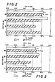
- Figure 2 is a graphical representation of the percent flood at the normal design point and the hydraulic load for the vapor for each of the four sections of the column illustrated in Figure 1.
- Figure 3 is a graphical representation of the percent flood at the normal design point and the hydraulic load for the vapor for each of four sections of a column.
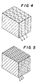
- Figure 4 is a simplified illustration of structured packing having a given packing density such as, for example, 500 square meters per cubic meter, wherein a, b, and c refer to separate packing elements.
- Figure 5 is a simplified illustration of structured packing having a greater packing density than the given packing density of the structured packing illustrated in Figure 4, wherein a, b, and c refer to separate packing elements.
- The invention will be described in detail with reference to the Drawings.
- Referring now to Figure 1 higher pressure feed air 1 is introduced into
column 2 which is the higher pressure column of a double column system. Withincolumn 2 the feed air is separated by cryogenic distillation into a nitrogen-enriched vapor and an oxygen-enriched liquid. Oxygen-enrichedliquid 3 is passed fromcolumn 2 into argon column top condenser20 wherein it is at least partially vaporized against condensing argon column top vapor, and then passed asvapor stream 21 andliquid stream 23 intocolumn 4 which is the lower pressure column of the double column system. Nitrogen-enrichedvapor 5 is passed intocondenser 6 wherein it is condensed by heat exchange withboiling column 4 bottoms. Resulting nitrogen-enriched liquid 7 is passed in part 8 intocolumn 2 as liquid reflux and inpart 9 intocolumn 4 as liquid reflux. Lower pressure feed air 22 may also be introduced intocolumn 4. Withincolumn 4 the feeds are separated by cryogenic distillation into nitrogen-rich and oxygen-rich portions. - Nitrogen-rich portion is removed from
column 4 asstream 10 and is recovered as product nitrogen. Oxygen-rich portion is removed fromcolumn 4 as stream 11 and is recovered as product oxygen. Awaste stream 12 is removed fromcolumn 4 for control purposes. A stream 13 comprising primarily oxygen and argon is taken fromcolumn 4 at an intermediate point of the column and passed intoargon column 14 wherein it is separated by cryogenic distillation into an argon-rich part and an oxygen-rich part. Argon-rich vapor is condensed in argoncolumn top condenser 20 and a portion is removed fromcolumn 14 asstream 15 and is recovered as product crude argon. Oxygen-rich part is removed fromcolumn 14 and is returned asstream 16 tocolumn 4. -
Column 4 has four sections labelled in Figure 1 as sections I, II, III and IV. Section I is defined by the take off points of streams 11 and 13, section II is defined by the take off point of stream 13 and the introduction point ofstreams streams stream 12, and section IV is defined by the takeoff points ofstreams - Because of the introduction and removal of fluid from
column 4 and of the changes in the composition of the fluid, the hydraulic load in one section differs significantly from that of another section. Hydraulic load for the vapor may be expressed as
- Mα = vapor flow rate (Ib/s),
- PG = vapor density (lb/ft3),
- PL = liquid density (lb/ft3),
- AT = cross sectional area (ft2), and
- CV = capacity factor (ft/s).
- Hydraulic load forthe liquid may be expressed as ML/(pLAT) where ML = liquid flow rate (lb/s).
- Due to the possibility of widely varying hydraulic load among the column sections an operating limitation is created because the column must be designed to accommodate that section which is most vulnerable to flooding in order to ensure that the column operates so that no section floods. Typically the section most vulnerable to flooding is operated at about 80 percent of flooding at the normal design point and the other section or sections operated at percentages of flooding less than this.
- The present invention addresses and solves this problem by employing structured packing of different densities in at least two sections of a column wherein the packing density of structured packing in a first section of the column differs from the packing density of structured packing in a second section of the column. As can be appreciated, the first section of the column may refer to any section of the column. Structured packing having densities within the range of from 250 to 1000 square meters per cubic meter is especially useful in the invention. The structured packing is employed so that the percentage flood at the design point for each section is preferably within 50 to 95 percent. The invention has to do with column rangeability, or load variations. Because of column feeds and draws and composition changes, each column section has different vapor and liquid loading, i.e. hydraulic loads. Using variable density packing one can maintain a given column diameter throughout the column and yet all sections can have acceptable rangeability.
- In a preferred embodiment of the invention, the packing density of the structured packing in at least one higher section exceeds the packing density in at least one lower section. In a particularly preferred embodiment of the invention the packing density of the structured packing in the lowermost section is exceeded by the packing density in at least one section above the lowermost section. In another preferred embodiment of the invention the packing density in the lowermost section of the column is less than 700 m2/m3.
- The packing density of structured packing within one section may also vary within the scope of this invention.
- The invention also addresses and solves another potential problem where oxygen is one of the components to be separated such as in the separation of a mixture comprising oxygen and nitrogen or in the separation of a mixture comprising oxygen and argon. A preferred construction material for structured packing is aluminum because of its lower cost. However, due to the thin cross-section of an individual structured packing element, questions have arisen regarding the flammability of aluminum structured packing in an environment where the oxygen concentration exceeds 21 percent. Accordingly copper has been suggested as a structured packing construction material in such instances (U.S. Patent No. 4,813,988-Bennett et al). Applicants have found through combustion tests involving packing elements and multiple packing elements that combustion is inhibited if an ignition event occurs at temperature and other process conditions representative of cryogenic distillation columns. Although not wishing to be held to any theory, it is believed that the closely spaced foil elements that comprise a packing element contribute to the combustion inhibition by improving heat dissipation from an ignition event. The aluminum content of the structured packing, i.e. the concentration of aluminum in the material from which the structured packing is made, may be within the range of from 50 to 99.99 percent. Thus with the use of structured packing of variable density and comprised of aluminum, cryogenic air separation can be carried out safely and efficiently, with improved column rangeability, and with reduced overall costs.
- The following example is presented for illustrative purposes and is not intended to be limiting.
- An air separation plant similar to that illustrated in Figure 1 was operated so as to produce 190 tons per day of oxygen at the design point. The plant employed aluminum structured packing in the lower pressure column of the double column arrangement.
- The packing in section of the column had a given density such as is illustrated in Figure 4 and the packing in section II had a density greater than that of the packing in section I such as is illustrated in Figure 5. In this case the packing in section I had a density of 500 m2/m3 and the packing section II had a density of 700 m2/m3. The packing in section III had a density of 350 m2/m3, and the packing in section IV had a density of 500 m2/m3. The column had an internal diameter of 1.33 m (52.5 inches) in all sections.
- Figure 2 is a graphical representation of the percentage flood at the design point and the capacity factor in each section. As can be seen the percentage flood in each section is within the range of 65 to 80 percent while the capacity factor in all sections exceeds 0.06 ft/sec, below which an unacceptably high HETP (height equivalent to a theoretical plate) occurs. Moreover the plant can operate successfully with a turndown limit as low as 67 percent.
- In U.S. Patent No. 4,836,836-Bennett et al there is discussed the HETP values which are necessary when separating argon and oxygen. Section I of the upper column of the embodiment of this invention illustrated in Figure 1 is used to separate a mixture containing argon and oxygen and, because the separation is difficult, a large number of theoretical stages are needed in section I. Bennett et al teach that if the packing HETP is in the range 193 to 208 mm (7.6 to 8.2 inches) then the use of packing will incur a large capital penalty compared with the use of trays. The reason for this is that the HETP for trays is lower than 193 to 208 mm (7.6-8.2 inches). Bennett et al further teach thatat HETP's of approximately 178 mm (7.0 inches) no capital penalty is incurred compared with trays and thus the use of structured packing having an HETP substantially lower than 193 to 208 mm (7.6 to 8.2 inches) is necessary for packing to be economic in section I on a capital cost basis. It follows then from the prior art that for choosing an appropriate packing density for section 1 one should choose it such that the HETP is significantly lower than 193 to 208 mm (7.6 to 8.2 inches). By experiment, in a 305 mm (12 inch) diameter laboratory column, the applicants have found t hat for t he separation of oxygen-argon mixtures by cryogenic distillation, the HETP using structured packing having a density of 500 m2/m3 is in the range of from 188 to 203 mm (7.4 to 8.0 inches and for structured packing having a density of 700 m2/m3 the HETP is in the range from 142 to 160 mm (5.6 to 6.3 inches). Given the generally accepted 15 percent increase in HETP due to fluid maldistribu- tion when translating laboratory data to the operation of full scale columns, this results in the teaching that packing having a density of at least 700 m2/m3 would be needed in section I.
- For many types of structured packing, HETP increases rapidly below some minimum value of CV. U.S. 4,836,836 shows a typical example where HETP rises rapidly when CV falls below about 0.06 ft/s. The reason for the fall-off in separating efficiency below a critical minimum value of CV is not clear. It could be due to reduced vapor turbulence which in turn reduces mass transfer coefficients or there may be some other explanation. Nevertheless, it is necessary to maintain the CV value above a minimum value of about 0.06 ft/s to avoid undue risk of malperformance. Now an air separation plant has to operate not only at its design point but also under turndown conditions. In the practice of this invention, as summarized in Figure 2, wherein structured packing of different density is employed in different column sections, and, in particular, where packing having a density of 500 m2/m3 is employed in section I and packing having a higher density is employed in at least one higher section, performance is improved. Because of the higher hydraulic capacity of the lower density packing in section I, the column diameter is set by section IV. CV in section II at the design point is 0.09 ft/s. Turndown is limited by section II but the turndown limit is

- If the operation of the plant illustrated in Figure 1 were operated using packing having a density of 700 m2/m3 in section I, the calculated results are graphically illustrated in Figure 3. Column capacity is now limited by section I and to maintain 80% flood at the design point, the column diameter must be increased to 1.49 m (58.5 inches). Because of the increased diameter, CV at the design point falls to 0.07 ft/sec in section II. Section II still limits the turndown but now the turndown limit is

- Thus the present invention comprises an advantageous deployment of different packing densities in the different sections of a column. The selection of the packing density in each section is determined taking into account the interrelationships between flooding, turndown, HETP and column diameter. Increased rangeability is achieved using structured packing having a lower density in the lowermost section than is suggested by the prior art.
Claims (20)
Applications Claiming Priority (2)
| Application Number | Priority Date | Filing Date | Title |
|---|---|---|---|
| US555039 | 1990-07-20 | ||
| US07/555,039 US5100448A (en) | 1990-07-20 | 1990-07-20 | Variable density structured packing cryogenic distillation system |
Publications (3)
| Publication Number | Publication Date |
|---|---|
| EP0467395A1 EP0467395A1 (en) | 1992-01-22 |
| EP0467395B1 true EP0467395B1 (en) | 1993-11-03 |
| EP0467395B2 EP0467395B2 (en) | 1999-11-17 |
Family
ID=24215730
Family Applications (1)
| Application Number | Title | Priority Date | Filing Date |
|---|---|---|---|
| EP91112131A Expired - Lifetime EP0467395B2 (en) | 1990-07-20 | 1991-07-19 | Variable density structured packing cryogenic distillation system |
Country Status (11)
| Country | Link |
|---|---|
| US (1) | US5100448A (en) |
| EP (1) | EP0467395B2 (en) |
| JP (1) | JPH0789015B2 (en) |
| KR (1) | KR960003269B1 (en) |
| CN (1) | CN1044155C (en) |
| BR (1) | BR9103112A (en) |
| CA (1) | CA2047411C (en) |
| DE (1) | DE69100586T3 (en) |
| ES (1) | ES2046828T5 (en) |
| ID (1) | ID1010B (en) |
| MX (1) | MX173997B (en) |
Cited By (1)
| Publication number | Priority date | Publication date | Assignee | Title |
|---|---|---|---|---|
| RU2107871C1 (en) * | 1992-03-20 | 1998-03-27 | Линде Акциенгезельшафт | Method of low-temperature separation of air and device for separation of air |
Families Citing this family (33)
| Publication number | Priority date | Publication date | Assignee | Title |
|---|---|---|---|---|
| FR2675568B1 (en) * | 1991-04-19 | 1993-07-16 | Air Liquide | PROCESS FOR THE CRYOGENIC SEPARATION OF MIXTURES CONTAINING OXYGEN AND TRIMS ORGANIZED FOR THE IMPLEMENTATION OF THIS PROCESS. |
| US5245832A (en) * | 1992-04-20 | 1993-09-21 | Praxair Technology, Inc. | Triple column cryogenic rectification system |
| US5282365A (en) * | 1992-11-17 | 1994-02-01 | Praxair Technology, Inc. | Packed column distillation system |
| US5419136A (en) * | 1993-09-17 | 1995-05-30 | The Boc Group, Inc. | Distillation column utilizing structured packing having varying crimp angle |
| US5396772A (en) * | 1994-03-11 | 1995-03-14 | The Boc Group, Inc. | Atmospheric gas separation method |
| GB9405161D0 (en) * | 1994-03-16 | 1994-04-27 | Boc Group Plc | Method and apparatus for reboiling a liquified gas mixture |
| JP3319174B2 (en) | 1994-09-19 | 2002-08-26 | 株式会社日立製作所 | Packing and air separation equipment |
| CN1091646C (en) * | 1994-10-04 | 2002-10-02 | 普莱克斯技术有限公司 | Structured packing with improved capacity for rectification systems |
| GB2302044A (en) * | 1995-06-12 | 1997-01-08 | William Harrold Aitken | Liquid-vapour contact apparatus |
| RU2193445C2 (en) * | 1995-07-08 | 2002-11-27 | Басф Аг | Pack contact members with ordered structure and low resistance from cloth or cloth-like materials for use in mass-exchange columns and method of rectification with use of said members |
| DE19524928A1 (en) * | 1995-07-08 | 1997-01-09 | Basf Ag | Process for the rectification of mixtures of high-boiling air and / or temperature sensitive substances, which require a high separation performance, in a fine vacuum, as well as columns suitable for this process |
| JPH09264667A (en) * | 1996-03-27 | 1997-10-07 | Teisan Kk | Ultra high purity nitrogen and oxygen production equipment |
| GB9607200D0 (en) * | 1996-04-04 | 1996-06-12 | Boc Group Plc | Air separation |
| US5644932A (en) * | 1996-05-21 | 1997-07-08 | Air Products And Chemicals, Inc. | Use of structured packing in a multi-sectioned air seperation unit |
| US5901575A (en) * | 1997-08-25 | 1999-05-11 | Air Products And Chemicals, Inc. | Stackable structured packing with controlled symmetry |
| US6244333B1 (en) | 1998-08-27 | 2001-06-12 | Zeks Air Drier Corporation | Corrugated folded plate heat exchanger |
| US6186223B1 (en) | 1998-08-27 | 2001-02-13 | Zeks Air Drier Corporation | Corrugated folded plate heat exchanger |
| US6101841A (en) * | 1998-10-02 | 2000-08-15 | Praxair Technology, Inc. | Cryogenic rectification system with high strength and high capacity packing |
| US5921109A (en) * | 1998-10-21 | 1999-07-13 | Praxair Technology, Inc. | Method for operating a cryogenic rectification column |
| US6425574B1 (en) * | 1998-12-18 | 2002-07-30 | Air Products And Chemicals, Inc. | Mixed-resistance structured packing |
| US6357728B1 (en) | 1999-03-15 | 2002-03-19 | Air Products And Chemicals, Inc. | Optimal corrugated structured packing |
| US6128922A (en) * | 1999-05-21 | 2000-10-10 | The Boc Group, Inc. | Distillation method and column |
| US6475349B1 (en) | 1999-09-24 | 2002-11-05 | The Boc Group, Inc. | Distillation column and method for promoting a uniform vapor flow |
| US6212907B1 (en) | 2000-02-23 | 2001-04-10 | Praxair Technology, Inc. | Method for operating a cryogenic rectification column |
| DE10010810A1 (en) * | 2000-03-08 | 2001-09-13 | Montz Gmbh Julius | Liquid distributor used in packing columns for distillation, absorption, gas scrubbing and other similar technical processes has at least one layer in a column with a specific surface area larger than the layer lying above and below it |
| US6321567B1 (en) | 2000-10-06 | 2001-11-27 | Praxair Technology, Inc. | Structured packing system for reduced distillation column height |
| US20030086846A1 (en) * | 2001-11-05 | 2003-05-08 | Adusei George Y. | Monolith stacking configuration for improved flooding |
| ATE356326T1 (en) | 2001-12-04 | 2007-03-15 | Air Prod & Chem | METHOD AND DEVICE FOR CRYOGENIC AIR SEPARATION |
| FR2854579B1 (en) * | 2003-05-09 | 2005-06-17 | Air Liquide | DISTILLATION PLANT COMPRISING COLUMNS WITH CORRUGATED-CROSS STRUCTURES AND METHOD OF INCREASING THE CAPACITY OF A DISTILLATION FACILITY |
| EP2645031A1 (en) * | 2012-03-29 | 2013-10-02 | Linde Aktiengesellschaft | Separating column for a low temperature air separator facility, low temperature air separator facility and method for low temperature separation of air |
| EP3327393A1 (en) * | 2016-11-25 | 2018-05-30 | Linde Aktiengesellschaft | Method and device for creating a high purity oxygen product flow by the cryogenic decomposition of air |
| FR3074058A1 (en) * | 2017-11-27 | 2019-05-31 | IFP Energies Nouvelles | IMPROVED METHOD OF DIMENSIONING A REGENERATION COLUMN OF AN ACID GAS CAPTURE OR GAS TREATMENT UNIT |
| KR102583733B1 (en) * | 2023-03-03 | 2023-09-27 | 백도 | Waterproofing device using Micro-cement of Crack repair material and Method for reinforcing concrete |
Family Cites Families (14)
| Publication number | Priority date | Publication date | Assignee | Title |
|---|---|---|---|---|
| US2047444A (en) * | 1935-01-14 | 1936-07-14 | Stedman Donald Frank | Packing for fractionating columns and the like |
| US2271671A (en) * | 1939-03-18 | 1942-02-03 | United Gas Improvement Co | Fractional distillation |
| NL102363C (en) * | 1953-11-12 | |||
| US4002705A (en) * | 1972-03-01 | 1977-01-11 | Mass Transfer Limited | Fluid-fluid contact apparatus |
| CH617357A5 (en) * | 1977-05-12 | 1980-05-30 | Sulzer Ag | |
| CH618006A5 (en) * | 1977-05-12 | 1980-06-30 | Sulzer Ag | |
| US4333894A (en) * | 1980-01-10 | 1982-06-08 | Veb Chemieanlagenbaukombinat Leipzig-Grimma | Mass-transfer column |
| AR243396A1 (en) * | 1985-01-18 | 1993-08-31 | Glitsch | Fractionation column |
| US4817393A (en) * | 1986-04-18 | 1989-04-04 | Erickson Donald C | Companded total condensation loxboil air distillation |
| US4871382A (en) * | 1987-12-14 | 1989-10-03 | Air Products And Chemicals, Inc. | Air separation process using packed columns for oxygen and argon recovery |
| US4836836A (en) * | 1987-12-14 | 1989-06-06 | Air Products And Chemicals, Inc. | Separating argon/oxygen mixtures using a structured packing |
| US4813988A (en) * | 1987-12-14 | 1989-03-21 | Air Products And Chemicals, Inc. | Suitable distillation column packing for the cryogenic separation of air |
| US4838913A (en) * | 1988-02-10 | 1989-06-13 | Union Carbide Corporation | Double column air separation process with hybrid upper column |
| US4929399A (en) * | 1988-03-17 | 1990-05-29 | Union Carbide Industrial Gases Technology Inc. | Structured column packing with liquid holdup |
-
1990
- 1990-07-20 US US07/555,039 patent/US5100448A/en not_active Expired - Lifetime
-
1991
- 1991-07-19 BR BR919103112A patent/BR9103112A/en not_active IP Right Cessation
- 1991-07-19 JP JP3203745A patent/JPH0789015B2/en not_active Expired - Fee Related
- 1991-07-19 DE DE69100586T patent/DE69100586T3/en not_active Expired - Lifetime
- 1991-07-19 MX MX9100295A patent/MX173997B/en unknown
- 1991-07-19 EP EP91112131A patent/EP0467395B2/en not_active Expired - Lifetime
- 1991-07-19 ES ES91112131T patent/ES2046828T5/en not_active Expired - Lifetime
- 1991-07-19 CN CN91105002A patent/CN1044155C/en not_active Expired - Lifetime
- 1991-07-19 CA CA002047411A patent/CA2047411C/en not_active Expired - Fee Related
- 1991-07-19 KR KR1019910012294A patent/KR960003269B1/en not_active Expired - Fee Related
- 1991-10-11 ID IDP54891A patent/ID1010B/en unknown
Cited By (1)
| Publication number | Priority date | Publication date | Assignee | Title |
|---|---|---|---|---|
| RU2107871C1 (en) * | 1992-03-20 | 1998-03-27 | Линде Акциенгезельшафт | Method of low-temperature separation of air and device for separation of air |
Also Published As
| Publication number | Publication date |
|---|---|
| DE69100586D1 (en) | 1993-12-09 |
| EP0467395A1 (en) | 1992-01-22 |
| ES2046828T3 (en) | 1994-02-01 |
| CA2047411A1 (en) | 1992-01-21 |
| CA2047411C (en) | 1994-01-11 |
| JPH0789015B2 (en) | 1995-09-27 |
| KR960003269B1 (en) | 1996-03-07 |
| ID1010B (en) | 1996-10-15 |
| KR920002192A (en) | 1992-02-28 |
| MX173997B (en) | 1994-04-13 |
| EP0467395B2 (en) | 1999-11-17 |
| ES2046828T5 (en) | 2000-03-01 |
| US5100448A (en) | 1992-03-31 |
| BR9103112A (en) | 1992-04-28 |
| CN1063756A (en) | 1992-08-19 |
| CN1044155C (en) | 1999-07-14 |
| DE69100586T3 (en) | 2000-05-25 |
| JPH04227461A (en) | 1992-08-17 |
| DE69100586T2 (en) | 1994-03-31 |
Similar Documents
| Publication | Publication Date | Title |
|---|---|---|
| EP0467395B2 (en) | Variable density structured packing cryogenic distillation system | |
| US5237823A (en) | Cryogenic air separation using random packing | |
| CN1091646C (en) | Structured packing with improved capacity for rectification systems | |
| EP0638778B1 (en) | Distillation system with partitioned column | |
| CA2279463C (en) | Method for operating a cryogenic rectification column | |
| US4838913A (en) | Double column air separation process with hybrid upper column | |
| EP0644389A1 (en) | Distillation column utilizing structured packing | |
| EP0598382A1 (en) | Improved packed column distillation system | |
| US5836174A (en) | Cryogenic rectification system for producing multi-purity oxygen | |
| CA2358269C (en) | Structured packing system for reduced distillation column height | |
| CN1135351C (en) | Column configuration and method for argon production | |
| US6128922A (en) | Distillation method and column |
Legal Events
| Date | Code | Title | Description |
|---|---|---|---|
| PUAI | Public reference made under article 153(3) epc to a published international application that has entered the european phase |
Free format text: ORIGINAL CODE: 0009012 |
|
| AK | Designated contracting states |
Kind code of ref document: A1 Designated state(s): BE DE ES FR GB IT NL |
|
| 17P | Request for examination filed |
Effective date: 19920212 |
|
| 17Q | First examination report despatched |
Effective date: 19921012 |
|
| RAP1 | Party data changed (applicant data changed or rights of an application transferred) |
Owner name: PRAXAIR TECHNOLOGY, INC. |
|
| ITF | It: translation for a ep patent filed | ||
| GRAA | (expected) grant |
Free format text: ORIGINAL CODE: 0009210 |
|
| AK | Designated contracting states |
Kind code of ref document: B1 Designated state(s): BE DE ES FR GB IT NL |
|
| REF | Corresponds to: |
Ref document number: 69100586 Country of ref document: DE Date of ref document: 19931209 |
|
| REG | Reference to a national code |
Ref country code: ES Ref legal event code: FG2A Ref document number: 2046828 Country of ref document: ES Kind code of ref document: T3 |
|
| ET | Fr: translation filed | ||
| PLBI | Opposition filed |
Free format text: ORIGINAL CODE: 0009260 |
|
| 26 | Opposition filed |
Opponent name: THE BOC GROUP PLC Effective date: 19940802 Opponent name: L'AIR LIQUIDE, S.A. POUR L'ETUDE ET L'EXPLOITATION Effective date: 19940801 |
|
| NLR1 | Nl: opposition has been filed with the epo |
Opponent name: THE BOC GROUP PLC Opponent name: L'AIR LIQUIDE, S.A. |
|
| APAC | Appeal dossier modified |
Free format text: ORIGINAL CODE: EPIDOS NOAPO |
|
| APAA | Appeal reference recorded |
Free format text: ORIGINAL CODE: EPIDOS REFN |
|
| APAC | Appeal dossier modified |
Free format text: ORIGINAL CODE: EPIDOS NOAPO |
|
| PLAW | Interlocutory decision in opposition |
Free format text: ORIGINAL CODE: EPIDOS IDOP |
|
| PUAH | Patent maintained in amended form |
Free format text: ORIGINAL CODE: 0009272 |
|
| STAA | Information on the status of an ep patent application or granted ep patent |
Free format text: STATUS: PATENT MAINTAINED AS AMENDED |
|
| ITF | It: translation for a ep patent filed | ||
| 27A | Patent maintained in amended form |
Effective date: 19991117 |
|
| AK | Designated contracting states |
Kind code of ref document: B2 Designated state(s): BE DE ES FR GB IT NL |
|
| NLR2 | Nl: decision of opposition | ||
| ET3 | Fr: translation filed ** decision concerning opposition | ||
| REG | Reference to a national code |
Ref country code: ES Ref legal event code: DC2A Kind code of ref document: T5 Effective date: 20000118 |
|
| NLR3 | Nl: receipt of modified translations in the netherlands language after an opposition procedure | ||
| REG | Reference to a national code |
Ref country code: GB Ref legal event code: IF02 |
|
| PGFP | Annual fee paid to national office [announced via postgrant information from national office to epo] |
Ref country code: NL Payment date: 20040629 Year of fee payment: 14 |
|
| PGFP | Annual fee paid to national office [announced via postgrant information from national office to epo] |
Ref country code: BE Payment date: 20040819 Year of fee payment: 14 |
|
| PG25 | Lapsed in a contracting state [announced via postgrant information from national office to epo] |
Ref country code: IT Free format text: LAPSE BECAUSE OF NON-PAYMENT OF DUE FEES Effective date: 20050719 |
|
| PG25 | Lapsed in a contracting state [announced via postgrant information from national office to epo] |
Ref country code: BE Free format text: LAPSE BECAUSE OF NON-PAYMENT OF DUE FEES Effective date: 20050731 |
|
| APAH | Appeal reference modified |
Free format text: ORIGINAL CODE: EPIDOSCREFNO |
|
| PG25 | Lapsed in a contracting state [announced via postgrant information from national office to epo] |
Ref country code: NL Free format text: LAPSE BECAUSE OF NON-PAYMENT OF DUE FEES Effective date: 20060201 |
|
| NLV4 | Nl: lapsed or anulled due to non-payment of the annual fee |
Effective date: 20060201 |
|
| BERE | Be: lapsed |
Owner name: *PRAXAIR TECHNOLOGY INC. Effective date: 20050731 |
|
| PGRI | Patent reinstated in contracting state [announced from national office to epo] |
Ref country code: IT Effective date: 20091201 |
|
| PGFP | Annual fee paid to national office [announced via postgrant information from national office to epo] |
Ref country code: ES Payment date: 20100726 Year of fee payment: 20 |
|
| PGFP | Annual fee paid to national office [announced via postgrant information from national office to epo] |
Ref country code: IT Payment date: 20100728 Year of fee payment: 20 Ref country code: DE Payment date: 20100728 Year of fee payment: 20 Ref country code: FR Payment date: 20100805 Year of fee payment: 20 |
|
| PGFP | Annual fee paid to national office [announced via postgrant information from national office to epo] |
Ref country code: GB Payment date: 20100726 Year of fee payment: 20 |
|
| REG | Reference to a national code |
Ref country code: DE Ref legal event code: R071 Ref document number: 69100586 Country of ref document: DE |
|
| REG | Reference to a national code |
Ref country code: DE Ref legal event code: R071 Ref document number: 69100586 Country of ref document: DE |
|
| REG | Reference to a national code |
Ref country code: GB Ref legal event code: PE20 Expiry date: 20110718 |
|
| PG25 | Lapsed in a contracting state [announced via postgrant information from national office to epo] |
Ref country code: GB Free format text: LAPSE BECAUSE OF EXPIRATION OF PROTECTION Effective date: 20110718 |
|
| PG25 | Lapsed in a contracting state [announced via postgrant information from national office to epo] |
Ref country code: DE Free format text: LAPSE BECAUSE OF EXPIRATION OF PROTECTION Effective date: 20110720 |
|
| REG | Reference to a national code |
Ref country code: ES Ref legal event code: FD2A Effective date: 20130722 |