EP0466834B1 - Temperature monitoring apparatus and method in a composting system - Google Patents
Temperature monitoring apparatus and method in a composting system Download PDFInfo
- Publication number
- EP0466834B1 EP0466834B1 EP90907742A EP90907742A EP0466834B1 EP 0466834 B1 EP0466834 B1 EP 0466834B1 EP 90907742 A EP90907742 A EP 90907742A EP 90907742 A EP90907742 A EP 90907742A EP 0466834 B1 EP0466834 B1 EP 0466834B1
- Authority
- EP
- European Patent Office
- Prior art keywords
- probe
- organic matter
- temperature
- vessel
- ram
- Prior art date
- Legal status (The legal status is an assumption and is not a legal conclusion. Google has not performed a legal analysis and makes no representation as to the accuracy of the status listed.)
- Expired - Lifetime
Links
- 238000009264 composting Methods 0.000 title claims abstract description 47
- 238000000034 method Methods 0.000 title claims abstract description 27
- 238000012544 monitoring process Methods 0.000 title claims abstract description 18
- 239000000523 sample Substances 0.000 claims abstract description 74
- 239000005416 organic matter Substances 0.000 claims abstract description 55
- 230000001105 regulatory effect Effects 0.000 claims abstract description 9
- 238000000605 extraction Methods 0.000 claims abstract description 3
- 238000000354 decomposition reaction Methods 0.000 claims description 2
- 230000000694 effects Effects 0.000 claims 1
- 238000005056 compaction Methods 0.000 abstract description 2
- 238000005273 aeration Methods 0.000 description 28
- 239000000463 material Substances 0.000 description 6
- 239000002361 compost Substances 0.000 description 4
- 239000012530 fluid Substances 0.000 description 4
- 238000012806 monitoring device Methods 0.000 description 4
- 238000006243 chemical reaction Methods 0.000 description 3
- 238000004891 communication Methods 0.000 description 2
- 230000008878 coupling Effects 0.000 description 2
- 238000010168 coupling process Methods 0.000 description 2
- 238000005859 coupling reaction Methods 0.000 description 2
- 239000010813 municipal solid waste Substances 0.000 description 2
- 239000010815 organic waste Substances 0.000 description 2
- 239000010802 sludge Substances 0.000 description 2
- 238000004065 wastewater treatment Methods 0.000 description 2
- 238000010276 construction Methods 0.000 description 1
- 230000001276 controlling effect Effects 0.000 description 1
- 238000001035 drying Methods 0.000 description 1
- 238000002347 injection Methods 0.000 description 1
- 239000007924 injection Substances 0.000 description 1
- 230000002452 interceptive effect Effects 0.000 description 1
- 238000005259 measurement Methods 0.000 description 1
- 239000011368 organic material Substances 0.000 description 1
- 230000035515 penetration Effects 0.000 description 1
- 239000002364 soil amendment Substances 0.000 description 1
- 239000002910 solid waste Substances 0.000 description 1
- 230000000087 stabilizing effect Effects 0.000 description 1
- 229910001220 stainless steel Inorganic materials 0.000 description 1
- 239000010935 stainless steel Substances 0.000 description 1
- 230000003068 static effect Effects 0.000 description 1
- XLYOFNOQVPJJNP-UHFFFAOYSA-N water Substances O XLYOFNOQVPJJNP-UHFFFAOYSA-N 0.000 description 1
Images

Classifications
-
- G—PHYSICS
- G01—MEASURING; TESTING
- G01K—MEASURING TEMPERATURE; MEASURING QUANTITY OF HEAT; THERMALLY-SENSITIVE ELEMENTS NOT OTHERWISE PROVIDED FOR
- G01K13/00—Thermometers specially adapted for specific purposes
- G01K13/10—Thermometers specially adapted for specific purposes for measuring temperature within piled or stacked materials
-
- C—CHEMISTRY; METALLURGY
- C05—FERTILISERS; MANUFACTURE THEREOF
- C05F—ORGANIC FERTILISERS NOT COVERED BY SUBCLASSES C05B, C05C, e.g. FERTILISERS FROM WASTE OR REFUSE
- C05F17/00—Preparation of fertilisers characterised by biological or biochemical treatment steps, e.g. composting or fermentation
- C05F17/90—Apparatus therefor
- C05F17/921—Devices in which the material is conveyed essentially horizontally between inlet and discharge means
- C05F17/936—Tunnels
-
- C—CHEMISTRY; METALLURGY
- C05—FERTILISERS; MANUFACTURE THEREOF
- C05F—ORGANIC FERTILISERS NOT COVERED BY SUBCLASSES C05B, C05C, e.g. FERTILISERS FROM WASTE OR REFUSE
- C05F17/00—Preparation of fertilisers characterised by biological or biochemical treatment steps, e.g. composting or fermentation
- C05F17/90—Apparatus therefor
- C05F17/993—Arrangements for measuring process parameters, e.g. temperature, pressure or humidity
-
- Y—GENERAL TAGGING OF NEW TECHNOLOGICAL DEVELOPMENTS; GENERAL TAGGING OF CROSS-SECTIONAL TECHNOLOGIES SPANNING OVER SEVERAL SECTIONS OF THE IPC; TECHNICAL SUBJECTS COVERED BY FORMER USPC CROSS-REFERENCE ART COLLECTIONS [XRACs] AND DIGESTS
- Y02—TECHNOLOGIES OR APPLICATIONS FOR MITIGATION OR ADAPTATION AGAINST CLIMATE CHANGE
- Y02P—CLIMATE CHANGE MITIGATION TECHNOLOGIES IN THE PRODUCTION OR PROCESSING OF GOODS
- Y02P20/00—Technologies relating to chemical industry
- Y02P20/141—Feedstock
- Y02P20/145—Feedstock the feedstock being materials of biological origin
-
- Y—GENERAL TAGGING OF NEW TECHNOLOGICAL DEVELOPMENTS; GENERAL TAGGING OF CROSS-SECTIONAL TECHNOLOGIES SPANNING OVER SEVERAL SECTIONS OF THE IPC; TECHNICAL SUBJECTS COVERED BY FORMER USPC CROSS-REFERENCE ART COLLECTIONS [XRACs] AND DIGESTS
- Y02—TECHNOLOGIES OR APPLICATIONS FOR MITIGATION OR ADAPTATION AGAINST CLIMATE CHANGE
- Y02W—CLIMATE CHANGE MITIGATION TECHNOLOGIES RELATED TO WASTEWATER TREATMENT OR WASTE MANAGEMENT
- Y02W30/00—Technologies for solid waste management
- Y02W30/40—Bio-organic fraction processing; Production of fertilisers from the organic fraction of waste or refuse
-
- Y—GENERAL TAGGING OF NEW TECHNOLOGICAL DEVELOPMENTS; GENERAL TAGGING OF CROSS-SECTIONAL TECHNOLOGIES SPANNING OVER SEVERAL SECTIONS OF THE IPC; TECHNICAL SUBJECTS COVERED BY FORMER USPC CROSS-REFERENCE ART COLLECTIONS [XRACs] AND DIGESTS
- Y10—TECHNICAL SUBJECTS COVERED BY FORMER USPC
- Y10S—TECHNICAL SUBJECTS COVERED BY FORMER USPC CROSS-REFERENCE ART COLLECTIONS [XRACs] AND DIGESTS
- Y10S435/00—Chemistry: molecular biology and microbiology
- Y10S435/813—Continuous fermentation
Definitions
- the invention relates to a method and apparatus for monitoring temperature during aerobic composting of organic waste matter.
- This temperature control is a critical part of the composting process. If the temperature of the organic matter is too low, the process will take too long to complete. On the other hand, if the temperature is too high, the process breaks down.
- the key to economically operating whatever equipment is used in the composting process is to achieve an optimum temperature for a selected time period in order to quickly and completely process the organic matter.
- One example of such a temperature and time period is to achieve an optimum temperature of 55°C for three days. In order to achieve this, the temperature of the organic matter must be controlled, and in order to control the temperature, some means of temperature monitoring is required.
- a monitoring device In order to control the temperature of the composting mass to the desired temperature in the horizontal composters using air to accelerate the process, a monitoring device is necessary to provide the temperature at a plurality of points throughout the mass.
- Temperature monitoring devices located at the perimeter of the composting chamber cannot provide appropriate temperature readings. Thus, a temperature monitoring device or method which probes into the mass of the organic matter is desired.
- a problem connected with monitoring temperature at the mid-point is related to the fact that the composting mass of organic matter moves through the composter and therefore any monitoring device used must accommodate such movement.
- GB-A-2199820 discloses the use of an elongate probe to measure the internal temperature of a static compost mass.
- the present invention provides a temperature monitoring apparatus for monitoring the temperature within a mass of organic matter moved through a composting vessel by means of a compacting ram.
- An elongated, stationary probe extends through the vessel from one end toward the other.
- a plurality of temperature measuring devices are mounted along the probe.
- the probe may extend through the ram and be provided with a sleeve for accommodating movement of the ram relative to the probe.
- a decoupling device provides for decoupling of the probe from a mounting base and an extraction device permits the probe to be extracted from the vessel for replacement thereof.
- the probe provides a method of monitoring temperature in the mass and a method of composting by monitoring temperature in the mass and regulating the temperature in response thereto.
- reference numeral 10 refers generally to a composting apparatus according to the particular exemplary embodiment of the present invention as shown and described herein.
- Composting apparatus 10 includes a hollow vessel 12 defined by walls 14.
- the vessel has a rectangular cross-section such that walls 14 include a floor 16, a top wall 17, and side walls 18 extending in parallel fashion between the floor 16 and top wall 17.
- Walls 14 define a chamber 20 within vessel 12.
- vessel 12 and its internal chamber 20 are elongated so as to take the form of a conduit.
- composting apparatus 10 could be a conventional horizontally oriented composter, with top-to-bottom compost flow, which is modified and improved as discussed in greater detail below.
- an inlet 22 having an infeed conveyor 26, whereby inlet 22 in conjunction with infeed conveyor 26 permits communication with chamber 20 within the vessel 12.
- outlet 28 At the opposite end of vessel 12 is an outlet 28.
- a ram 30 driven by a set of actuators 32, which preferably are hydraulic cylinders but which could also be pneumatic cylinders or screw jacks. If actuators 32 are indeed hydraulic cylinders, they are actuated by a source 34 of pressurized hydraulic fluid shown schematically in Fig. 4, which pressure source 34 communicates with actuators 32 via hydraulic fluid lines 35.
- the source 34 of pressurized hydraulic fluid is a pump feeding hydraulic fluid in the form of oil to actuators 32 via hydraulic line 35 to move the ram 30.
- Organic matter such as sludge from a waste water treatment system or solid waste or garbage, is fed into the composting apparatus 10 via infeed conveyor 26 in a direction shown by arrow 37 (Fig. 1.)
- the organic matter is fed into chamber 20 at the end thereof adjacent inlet 22 and is deposited in front of ram 30.
- Actuators 32 are actuated to move ram 30 in a direction toward outlet 28 in order to advance the charge of organic matter 36 through composting apparatus 10.
- the advancing stroke of ram 30 is shown in phantom lines in Fig. 3.
- the distance between the retracted position of ram 30 as shown in solid lines in Fig. 3 and the fully advanced position as shown in phantom lines in Fig. 3 represents the volume of one charge of organic matter 36 fed into the composting apparatus 10 during one infeed operation. After such an infeed operation, ram 30 remains in this fully advanced position until it is retracted to the solid line position shown in Fig. 3 when the next infeed operation is initiated.
- a temperature probe 82 is preferably formed of stainless steel and comprises a plurality of sections appropriately connected together to provide a desired length. It is contemplated that a first end 104 of probe 82 may be attached to a reaction wall 106 adjacent inlet 22 and extend through ram 30 by means of a sleeve member 108 concentrically disposed on probe 82. Sleeve member 108 is attached to ram 30 via a collar 110. Probe 82 extends in the direction of movement of the organic matter and terminates at a second end 112 adjacent outlet end 28 of apparatus 10. Second end 112 includes an eyebolt 114. In this manner, probe 82 extends through the organic matter 36 and ram 30 is permitted to move relative to probe 82 by virtue of sleeve member 108. Thus, probe 82 is supported at first end 104 by reaction wall 106 and sleeve member 108, and at second end 112 by the mass of organic matter 36.
- At least one of such probes 82 may extend from the outlet end 28 of the vessel 12 toward the inlet end 22 and terminate just short of the advanced position of ram 30 so as not to interfere with the advancing stroke of ram 30.
- Movement of the organic matter 36 during compaction by ram 30 produces stabilizing forces on probe 82 which keep probe 82 in the same relative position in the organic matter 36.
- the sliding motion of the mass along probe 36 cleans the probe surface.
- a coupling 116 defined by a pair of spaced apart collars 118, located between ram 30 and reaction wall 106, is disconnected and a cable may be attached to the longer piece of the probe at 118.
- a second cable may be attached to eyebolt 114 and may be used to pull the probe from the organic matter in the direction of outlet 28. The first cable is pulled into the resulting hole in the compacted organic matter 36 formed by the probe 82. Once the old probe has been removed, the first cable may be attached to a new probe and the new probe pulled toward the inlet 22 into the probe hole in the organic matter 36. The first cable is removed and the new probe is attached at the coupling 116.
- the surface 120 of probe 82 is provided with a plurality of temperature measure devices (TMD's) 83 in such a manner that a group of preferably three TMD's 83 are provided in each zone (to be described later) in a manner such that one TMD is centrally positioned in each zone and adjacent TMD's are equally spaced on opposite sides of the centrally positioned TMD.
- TMD's include thermocouples and resistance temperature devices.
- the three TMD's in each zone are preferably wired in parallel to provide an average readout for each zone. By using three TMD's per zone, the probe 82 will still provide a signal representing the temperature of a zone in the event of failure of one or two of the TMD's in that zone.
- Wires 122 from the TMD's 83 extend through probe 82 and exit at conduit 124 adjacent first end 104.
- a plurality of probes 82 may be used in one composter, the key being that all such probes 82 extend along the composter in the direction of movement of the organic matter 36, i.e., the axis of each probe 82 is parallel with the direction of movement of the mass of organic matter 36.
- Probe 82 of the type described above may be used in connection with a vessel 12 including in the floor 16, a set of floor-mounted diffusers or orifices 40 distributed along virtually the entire length of vessel 12 for providing aeration air thereto.
- These diffusers 40 communicate with chamber 20 of vessel 12 to permit pressurized air to be injected into chamber 20.
- the air injection is accomplished via air passages 42 in floor 16, which air passages are fed by an air header 43 disposed in outlet vessel 12.
- air header 43 communicates with the series of air passages 42 which, in turn, communicate with diffusers 40 for injecting air into chamber 20.
- a source of aeration air provides air for effecting aeration and temperature control of the organic matter 36 to convert it to compost in a known manner.
- the aeration air is generated by a blower 51 driven by electric motor 52.
- Aeration air is fed into air header 43 to then pass through air passages 42 in floor 16 of chamber 20 and thence through diffusers 40 for aeration of the organic matter 36 to aid in composting.
- a selected portion of the set of diffusers or orifices 40 may act as suction orifices or inlets for return of aeration air which has been introduced into the organic matter 36 by others of the diffusers or orifices 40. By providing that some of the orifices 40 act as air returns, circulation through the organic matter 36 may be improved and the temperature better regulated.
- This aeration air return is accomplished via a suction fan 54 driven by a motor 56.
- Suction fan 54 pulls air through valve 200 and communicates with the suction header 58 which, in turn, selectively communicates with a certain portion of the air passages 42.
- air passages 42 When certain of the air passages 42 are in communication with suction header 58, air passages 42 then act as air returns for drawing aeration air from organic matter 36 to enhance circulation of aeration air.
- valves 60 preferably in the form of electronically controlled valves such as solenoid valves.
- a valve 60 will be disposed between each air passage 42 and the air header 43 and suction header 58.
- Separate zones (previously mentioned) of pressure and suction diffusers may be provided. In the particular exemplary embodiment shown and described, there are five zones of four air passages per zone. Each zone may correspond generally with a charge of material fed into vessel 12 by one infeed operation and one stroke of ram 30.
- a zone may hold more or less than one charge of material.
- certain conventional composters have approximately three charges located in a particular zone at a given time. Regardless of the amount of material therein, one such zone may be put under pressure, the next under suction, and so on in an alternating fashion.
- the aeration air system includes an aeration control 64 coupled with the valve 49 and/or the blower 51 which produces aeration air, and more specifically with the motor 52 of that blower.
- Aeration control 64 is preferably electronic and sends electrical signals to valve 49 and/or motor 52 of blower 51 to regulate the intensity of aeration air produced by blower 51.
- suction air control 66 for energizing motor 56 of suction fan 54 and for regulating its/their operation.
- suction air control 66 is electronic.
- both of the controls 64 and 66 be coupled with a master controller 70 shown schematically in Fig. 4.
- Master controller 70 acts as a central station from which aeration air and suction air may be controlled.
- Master controller 70 is connected to the aeration system via line 74 running to aeration control 64.
- aeration-producing control 64 is coupled to motor 52 of blower 51 via line 75 and/or connected to valve 49 via line 201.
- the master controller 70 is preferably also coupled with valves 60 which determines the pattern of which air passages 42 and orifices 40 are under pressure and which, if any, are under suction.
- master controller 70 provides the appropriate signals to valves 60 over a line 76 (Fig. 4).
- Master controller 70 controls the suction air by sending signals to suction control 66 over line 78.
- suction control 66 is coupled with motor 56 of suction fan 54 by line 79 and/or with valve 200 by line 202.
- Master control 70 also controls the operation of the ram 30 which is driven by hydraulic cylinders 32. Further, master controller 70 requires input from temperature probe 82.
- temperature probe 82 preferably extends axially along the geometric center of chamber 20 between inlet 22 and outlet 28 to measure the temperature of the organic matter 36 in the various zones of the composting apparatus 10.
- Signals from the temperature measuring devices 83 in each zone along the length of the probe 82 are preferably fed from wires 122 back over line 84 to master controller 70 to actuate the aeration air in a pattern (e.g., all pressure or a combination of pressure and/or suction) and at an intensity which will produce an optimum temperature in the organic mass as determined by experience and/or by an algorithm or program utilized by master controller 70.
- a pattern e.g., all pressure or a combination of pressure and/or suction
- a suitable temperature control such as a PID (proportional integral derivative) type controller can be incorporated into master controller 70 to receive temperature information via the temperature measuring devices 83 in a given zone or zones of probe 82 and, in response to an undesirable temperature of the organic matter 36 in that zone or zones, controller 70 may automatically actuate one or more of the blower 51, valve 49, suction fan 54 and valve 200 in combination with actuating appropriate valves 60 to cause orifices 40 to act as suction orifices or inlets thereby improving the circulation of aeration air through the organic matter 36 in order to maintain a desired temperature at the appropriate zone or zones penetrated by probe 82.
- PID proportional integral derivative
Landscapes
- Chemical & Material Sciences (AREA)
- Chemical Kinetics & Catalysis (AREA)
- Microbiology (AREA)
- Life Sciences & Earth Sciences (AREA)
- Organic Chemistry (AREA)
- Engineering & Computer Science (AREA)
- Biochemistry (AREA)
- Health & Medical Sciences (AREA)
- Biotechnology (AREA)
- General Chemical & Material Sciences (AREA)
- Molecular Biology (AREA)
- Physics & Mathematics (AREA)
- General Physics & Mathematics (AREA)
- Fertilizers (AREA)
- Processing Of Solid Wastes (AREA)
- Treatment Of Sludge (AREA)
- Alarm Systems (AREA)
Abstract
Description
- The invention relates to a method and apparatus for monitoring temperature during aerobic composting of organic waste matter.
- It is known to compost organic waste material, such as sludge from a waste water treatment facility or garbage, utilizing mechanical composting bins or vessels and pressurized aeration channels. The goal is to produce a nonodorous organic material which can often be sold as a soil amendment and which at least is not costly and objectionable to dispose of. In the process, the amount of water in the composting material is reduced, thus resulting in drying of the organic matter to further alleviate the disposal problem.
- The usual proposals for mechanical composting have involved upright, cylindrical devices in the nature of silos through which pressurized aeration air is circulated to aid in the decomposition process. As an alternative to vertical composting silos, it is known to provide a horizontal composting method and apparatus of a simple construction in which organic matter is moved horizontally along the length of the composting vessel in a stepwise fashion with the use of an actuated ram. Diffusers have been used along the length of the vessel to inject aeration air into the organic matter to aid in carrying out the composting process in a relatively short period of time by controlling the temperature (see e.g. US-A-4 436 817).
- This temperature control is a critical part of the composting process. If the temperature of the organic matter is too low, the process will take too long to complete. On the other hand, if the temperature is too high, the process breaks down. The key to economically operating whatever equipment is used in the composting process is to achieve an optimum temperature for a selected time period in order to quickly and completely process the organic matter. One example of such a temperature and time period is to achieve an optimum temperature of 55°C for three days. In order to achieve this, the temperature of the organic matter must be controlled, and in order to control the temperature, some means of temperature monitoring is required.
- In order to control the temperature of the composting mass to the desired temperature in the horizontal composters using air to accelerate the process, a monitoring device is necessary to provide the temperature at a plurality of points throughout the mass.
- Temperature monitoring devices located at the perimeter of the composting chamber cannot provide appropriate temperature readings. Thus, a temperature monitoring device or method which probes into the mass of the organic matter is desired.
- A problem connected with monitoring temperature at the mid-point is related to the fact that the composting mass of organic matter moves through the composter and therefore any monitoring device used must accommodate such movement.
- GB-A-2199820 discloses the use of an elongate probe to measure the internal temperature of a static compost mass.
- It is therefore an object of the present invention to provide a composting method and apparatus in which the average temperature of the mass of organic matter is monitored and controlled.
- It is a related object of the present invention to provide a composting method and apparatus in which such temperature monitoring and control is achieved in a mechanically simple an inexpensive manner.
- It is yet another object of the present invention to provide a composting method and apparatus in which such temperature monitoring and control accommodates the moving mass of organic matter through the chamber.
- It is a further object of the present invention to provide a composting method and apparatus in which the provision of aeration air circulating through the organic matter to regulate the temperature thereof is responsive to the monitored temperature of the mass.
- It is yet a further object of the present invention to provide automatic control of air circulation and penetration in response to predetermined temperature changes sensed by the temperature monitoring apparatus.
- These and other objects and advantages of the present invention will be more fully brought out in the description which follows with reference to the accompanying drawings.
- To achieve the foregoing objects, the present invention provides a temperature monitoring apparatus for monitoring the temperature within a mass of organic matter moved through a composting vessel by means of a compacting ram. An elongated, stationary probe extends through the vessel from one end toward the other. A plurality of temperature measuring devices are mounted along the probe. The probe may extend through the ram and be provided with a sleeve for accommodating movement of the ram relative to the probe. A decoupling device provides for decoupling of the probe from a mounting base and an extraction device permits the probe to be extracted from the vessel for replacement thereof. The probe provides a method of monitoring temperature in the mass and a method of composting by monitoring temperature in the mass and regulating the temperature in response thereto.
-
- Fig. 1 is a perspective view, partially cut away, of an embodiment of a composting apparatus according to the present invention;
- Fig. 2 is an enlarged, fragmentary, detailed sectional view showing in closeup the relationship between the charge of organic matter and the floor of the composting apparatus;
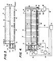
- Fig. 3 is a side view in cross-section of an embodiment of the composting apparatus of Fig. 1 taken along the line 3-3 of Fig. 1;
- Fig. 4 is a top view in cross-section of an embodiment of the composting apparatus taken along the line 4-4 of Fig. 1 and showing the control system for the composting apparatus in schematic form; and
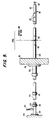
- Fig. 5 is a side view of an embodiment of the temperature probe according to the present invention.
- By way of background and introduction, a composting system of a type with which the method and apparatus for temperature monitoring and control may be used will first be described.
- In this regard,
reference numeral 10 refers generally to a composting apparatus according to the particular exemplary embodiment of the present invention as shown and described herein.Composting apparatus 10 includes ahollow vessel 12 defined bywalls 14. In the particular embodiment as shown and described, the vessel has a rectangular cross-section such thatwalls 14 include afloor 16, atop wall 17, andside walls 18 extending in parallel fashion between thefloor 16 andtop wall 17.Walls 14 define achamber 20 withinvessel 12. As will be seen from the drawings,vessel 12 and itsinternal chamber 20 are elongated so as to take the form of a conduit. Of course,composting apparatus 10 could be a conventional horizontally oriented composter, with top-to-bottom compost flow, which is modified and improved as discussed in greater detail below. - At one end of
vessel 12 is aninlet 22 having aninfeed conveyor 26, wherebyinlet 22 in conjunction withinfeed conveyor 26 permits communication withchamber 20 within thevessel 12. At the opposite end ofvessel 12 is anoutlet 28. - Within
chamber 20adjacent inlet 22 is aram 30 driven by a set ofactuators 32, which preferably are hydraulic cylinders but which could also be pneumatic cylinders or screw jacks. Ifactuators 32 are indeed hydraulic cylinders, they are actuated by asource 34 of pressurized hydraulic fluid shown schematically in Fig. 4, whichpressure source 34 communicates withactuators 32 viahydraulic fluid lines 35. Preferably, thesource 34 of pressurized hydraulic fluid is a pump feeding hydraulic fluid in the form of oil toactuators 32 viahydraulic line 35 to move theram 30. - Organic matter, such as sludge from a waste water treatment system or solid waste or garbage, is fed into the
composting apparatus 10 via infeedconveyor 26 in a direction shown by arrow 37 (Fig. 1.) The organic matter is fed intochamber 20 at the end thereofadjacent inlet 22 and is deposited in front ofram 30.Actuators 32 are actuated to moveram 30 in a direction towardoutlet 28 in order to advance the charge oforganic matter 36 throughcomposting apparatus 10. The advancing stroke ofram 30 is shown in phantom lines in Fig. 3. - The distance between the retracted position of
ram 30 as shown in solid lines in Fig. 3 and the fully advanced position as shown in phantom lines in Fig. 3 represents the volume of one charge oforganic matter 36 fed into thecomposting apparatus 10 during one infeed operation. After such an infeed operation,ram 30 remains in this fully advanced position until it is retracted to the solid line position shown in Fig. 3 when the next infeed operation is initiated. - As new charges of material are advanced through the
vessel 12 via the infeed operation in advance of theram 30, earlier charges oforganic matter 36 which have advanced entirely throughvessel 12 and with respect to which the composting operation has been completed are discharged fromvessel 12 viaoutlet 28. The direction of discharge is illustrated byarrow 38 in Fig. 1. - A
temperature probe 82 is preferably formed of stainless steel and comprises a plurality of sections appropriately connected together to provide a desired length. It is contemplated that afirst end 104 ofprobe 82 may be attached to areaction wall 106adjacent inlet 22 and extend throughram 30 by means of asleeve member 108 concentrically disposed onprobe 82. Sleevemember 108 is attached toram 30 via acollar 110.Probe 82 extends in the direction of movement of the organic matter and terminates at asecond end 112adjacent outlet end 28 ofapparatus 10.Second end 112 includes aneyebolt 114. In this manner,probe 82 extends through theorganic matter 36 andram 30 is permitted to move relative to probe 82 by virtue ofsleeve member 108. Thus,probe 82 is supported atfirst end 104 byreaction wall 106 andsleeve member 108, and atsecond end 112 by the mass oforganic matter 36. - It is also contemplated, as an alternative embodiment, that at least one of
such probes 82 may extend from the outlet end 28 of thevessel 12 toward theinlet end 22 and terminate just short of the advanced position ofram 30 so as not to interfere with the advancing stroke ofram 30. - Movement of the
organic matter 36 during compaction byram 30 produces stabilizing forces onprobe 82 which keepprobe 82 in the same relative position in theorganic matter 36. The sliding motion of the mass alongprobe 36 cleans the probe surface. - Should replacement of the probe be required, a
coupling 116 defined by a pair of spaced apartcollars 118, located betweenram 30 andreaction wall 106, is disconnected and a cable may be attached to the longer piece of the probe at 118. A second cable may be attached toeyebolt 114 and may be used to pull the probe from the organic matter in the direction ofoutlet 28. The first cable is pulled into the resulting hole in the compactedorganic matter 36 formed by theprobe 82. Once the old probe has been removed, the first cable may be attached to a new probe and the new probe pulled toward theinlet 22 into the probe hole in theorganic matter 36. The first cable is removed and the new probe is attached at thecoupling 116. - The
surface 120 ofprobe 82 is provided with a plurality of temperature measure devices (TMD's) 83 in such a manner that a group of preferably three TMD's 83 are provided in each zone (to be described later) in a manner such that one TMD is centrally positioned in each zone and adjacent TMD's are equally spaced on opposite sides of the centrally positioned TMD. Examples of TMD's include thermocouples and resistance temperature devices. The three TMD's in each zone are preferably wired in parallel to provide an average readout for each zone. By using three TMD's per zone, theprobe 82 will still provide a signal representing the temperature of a zone in the event of failure of one or two of the TMD's in that zone.Wires 122 from the TMD's 83 extend throughprobe 82 and exit atconduit 124 adjacentfirst end 104. - If desired, a plurality of
probes 82 may be used in one composter, the key being that allsuch probes 82 extend along the composter in the direction of movement of theorganic matter 36, i.e., the axis of eachprobe 82 is parallel with the direction of movement of the mass oforganic matter 36. - Probe 82 of the type described above may be used in connection with a
vessel 12 including in thefloor 16, a set of floor-mounted diffusers ororifices 40 distributed along virtually the entire length ofvessel 12 for providing aeration air thereto. Thesediffusers 40 communicate withchamber 20 ofvessel 12 to permit pressurized air to be injected intochamber 20. The air injection is accomplished viaair passages 42 infloor 16, which air passages are fed by anair header 43 disposed inoutlet vessel 12. Thus,air header 43 communicates with the series ofair passages 42 which, in turn, communicate withdiffusers 40 for injecting air intochamber 20. - In the particular exemplary embodiment shown, there is a source of aeration air. This source provides air for effecting aeration and temperature control of the
organic matter 36 to convert it to compost in a known manner. The aeration air is generated by ablower 51 driven byelectric motor 52. Aeration air is fed intoair header 43 to then pass throughair passages 42 infloor 16 ofchamber 20 and thence throughdiffusers 40 for aeration of theorganic matter 36 to aid in composting. - A selected portion of the set of diffusers or
orifices 40 may act as suction orifices or inlets for return of aeration air which has been introduced into theorganic matter 36 by others of the diffusers ororifices 40. By providing that some of theorifices 40 act as air returns, circulation through theorganic matter 36 may be improved and the temperature better regulated. - This aeration air return is accomplished via a
suction fan 54 driven by amotor 56.Suction fan 54 pulls air throughvalve 200 and communicates with thesuction header 58 which, in turn, selectively communicates with a certain portion of theair passages 42. When certain of theair passages 42 are in communication withsuction header 58,air passages 42 then act as air returns for drawing aeration air fromorganic matter 36 to enhance circulation of aeration air. - Selection of which of
orifices 40 will act as diffusers for introducing aeration air intochamber 20 and which oforifices 40, and associatedair passages 42, will act as air returns is determined by a series ofvalves 60, preferably in the form of electronically controlled valves such as solenoid valves. Preferably, too, such avalve 60 will be disposed between eachair passage 42 and theair header 43 andsuction header 58. Separate zones (previously mentioned) of pressure and suction diffusers may be provided. In the particular exemplary embodiment shown and described, there are five zones of four air passages per zone. Each zone may correspond generally with a charge of material fed intovessel 12 by one infeed operation and one stroke ofram 30. Alternatively, a zone may hold more or less than one charge of material. For example, certain conventional composters have approximately three charges located in a particular zone at a given time. Regardless of the amount of material therein, one such zone may be put under pressure, the next under suction, and so on in an alternating fashion. - The aeration air system includes an
aeration control 64 coupled with thevalve 49 and/or theblower 51 which produces aeration air, and more specifically with themotor 52 of that blower.Aeration control 64 is preferably electronic and sends electrical signals tovalve 49 and/ormotor 52 ofblower 51 to regulate the intensity of aeration air produced byblower 51. - Just as the sources of aeration air have controls, so too the source of suction air, i.e., the
valve 200 and/or thesuction fan 54 driven bymotor 56, has asuction air control 66 for energizingmotor 56 ofsuction fan 54 and for regulating its/their operation. Preferably, too,suction air control 66 is electronic. - It is preferred that both of the
controls master controller 70 shown schematically in Fig. 4.Master controller 70 acts as a central station from which aeration air and suction air may be controlled. -
Master controller 70 is connected to the aeration system vialine 74 running toaeration control 64. In turn, aeration-producingcontrol 64 is coupled tomotor 52 ofblower 51 vialine 75 and/or connected tovalve 49 vialine 201. Themaster controller 70 is preferably also coupled withvalves 60 which determines the pattern of whichair passages 42 andorifices 40 are under pressure and which, if any, are under suction. In this regard,master controller 70 provides the appropriate signals tovalves 60 over a line 76 (Fig. 4).Master controller 70 controls the suction air by sending signals tosuction control 66 overline 78. In turn,suction control 66 is coupled withmotor 56 ofsuction fan 54 byline 79 and/or withvalve 200 byline 202.Master control 70 also controls the operation of theram 30 which is driven byhydraulic cylinders 32. Further,master controller 70 requires input fromtemperature probe 82. - The pattern of aeration utilizing pressure or pressure and suction for
air passages 42 and theirorifices 40 will be determined in part by the temperature of the mass oforganic matter 36 as measured bytemperature probe 82. Thus,temperature probe 82 preferably extends axially along the geometric center ofchamber 20 betweeninlet 22 andoutlet 28 to measure the temperature of theorganic matter 36 in the various zones of thecomposting apparatus 10. Signals from thetemperature measuring devices 83 in each zone along the length of theprobe 82 are preferably fed fromwires 122 back overline 84 tomaster controller 70 to actuate the aeration air in a pattern (e.g., all pressure or a combination of pressure and/or suction) and at an intensity which will produce an optimum temperature in the organic mass as determined by experience and/or by an algorithm or program utilized bymaster controller 70. Of course, the ability to accomplish this is generally enhanced bytemperature probe 82 which provides an accurate measurement of temperature deep within the mass of organic matter without interfering with the flow of organic matter through the composting apparatus. - A suitable temperature control such as a PID (proportional integral derivative) type controller can be incorporated into
master controller 70 to receive temperature information via thetemperature measuring devices 83 in a given zone or zones ofprobe 82 and, in response to an undesirable temperature of theorganic matter 36 in that zone or zones,controller 70 may automatically actuate one or more of theblower 51,valve 49,suction fan 54 andvalve 200 in combination with actuatingappropriate valves 60 to causeorifices 40 to act as suction orifices or inlets thereby improving the circulation of aeration air through theorganic matter 36 in order to maintain a desired temperature at the appropriate zone or zones penetrated byprobe 82.
Claims (16)
- A composting apparatus (10) for accelerated aerobic decomposition of organic matter, the apparatus comprising:
a composting vessel (12) through which the organic matter is moved to effect composting; and
means (40) for aerating the organic matter as it moves through said composting vessel;
characterized by
at least one elongated probe (82) extending from a first end of said vessel (12) toward a second end of said vessel such that, when said vessel (12) is filled with organic matter, said probe (82) is supported by the moving organic matter;
a plurality of temperature measuring devices (83) mounted along the probe (82). - The apparatus of claim 1 comprising:
a ram (30) for moving the organic matter from said first end of said vessel (12) toward said second end thereof; and
means (108) mounted on the ram (30) for accommodating movement of the ram relative to the probe (82). - The apparatus of claim 1 or 2, wherein the plurality of temperature measuring devices (83) are spaced apart in groups.
- The apparatus of any of claims 1 to 3, wherein the probe (82) includes a decoupling device (116) adjacent the first end of the vessel (12) and an extraction device (114) adjacent the second end of the vessel (12).
- The apparatus of claim 2, wherein said means mounted on the ram comprises a sleeve (108) having a flange (110) for connection to the ram (30).
- The apparatus of any of claims 1 to 5 comprising:means (64, 70) for regulating the temperature in a chamber defined in said vessel (12), said temperature regulating means (64, 70) being coupled with said probe (82).
- The apparatus of claim 6, wherein said chamber is elongated and has a rectangular cross-section.
- The apparatus of claim 7, wherein said probe (82) extends through the geometric center of said cross-section and coaxially with respect to said lengthwise axis.
- The apparatus of claim 6, including:
a sleeve (108) slidably mounted on said probe (82), said sleeve being mounted in said ram (30) to permit said ram (30) to move relative to said probe (82). - The apparatus of claim 9, wherein a first end of said probe (82) is mounted in a wall (106) adjacent said ram (30), said probe (82) extending through said ram (30) via said sleeve (108).
- The apparatus of claim 10, including:
an eyebolt (114) connected to a second end of said probe (82) opposite said first end. - The apparatus of any of claims 1 to 11, wherein the probe (82) is stationary.
- A method of monitoring the temperature in a mass of organic matter moved through a composting vessel (12), including the steps of:
surrounding at least one elongated probe (82) with a mass of organic matter to be composted;
moving the mass of organic matter through the composting vessel (12) in the same direction as that in with the elongated probe (82) extends; and
measuring the temperature of the interior of the mass or organic matter at a plurality of locations along the probe (82). - A method of composting by monitoring the temperature of a mass of organic matter moved through a composting vessel (12) and regulating the temperature in response thereto, including the steps of:
surrounding at least one elongated probe with a mass of organic matter to be composted;
moving the mass of organic matter through the composting vessel (12) in the same direction as that in with the elongated probe (82) extends;
measuring the temperature of the interior of the mass of organic matter at a plurality of locations along the probe (82); and
regulating the temperature in the vessel by temperature regulating means (64, 70) coupled with said probe (82). - The method of claim 14, wherein the organic matter is moved by a ram (30).
- The method of claim 15 including the additional step of:
mounting a bearing (108) on the probe (82) for accommodating movement of the ram (30) relative to the stationary probe (82).
Applications Claiming Priority (3)
| Application Number | Priority Date | Filing Date | Title |
|---|---|---|---|
| US337868 | 1989-04-14 | ||
| US07/337,868 US5049486A (en) | 1989-04-14 | 1989-04-14 | Temperature monitoring apparatus and method in a composting system through which organic matter is moved to effect composting |
| PCT/US1990/001118 WO1990012893A1 (en) | 1989-04-14 | 1990-03-09 | Temperature monitoring apparatus and method in a composting system |
Publications (3)
| Publication Number | Publication Date |
|---|---|
| EP0466834A1 EP0466834A1 (en) | 1992-01-22 |
| EP0466834A4 EP0466834A4 (en) | 1992-03-18 |
| EP0466834B1 true EP0466834B1 (en) | 1995-12-27 |
Family
ID=23322364
Family Applications (1)
| Application Number | Title | Priority Date | Filing Date |
|---|---|---|---|
| EP90907742A Expired - Lifetime EP0466834B1 (en) | 1989-04-14 | 1990-03-09 | Temperature monitoring apparatus and method in a composting system |
Country Status (8)
| Country | Link |
|---|---|
| US (1) | US5049486A (en) |
| EP (1) | EP0466834B1 (en) |
| AT (1) | ATE132199T1 (en) |
| AU (1) | AU5529190A (en) |
| CA (1) | CA1330891C (en) |
| DE (1) | DE69024488T2 (en) |
| ES (1) | ES2085907T3 (en) |
| WO (1) | WO1990012893A1 (en) |
Families Citing this family (20)
| Publication number | Priority date | Publication date | Assignee | Title |
|---|---|---|---|---|
| US5248612A (en) * | 1989-10-30 | 1993-09-28 | Ashbrook-Simon-Hartley Corporation | Apparatus for composting using improved charging and discharging sequence |
| US5204263A (en) * | 1991-09-27 | 1993-04-20 | Bedminster Bioconversion Corporation | Channel cover |
| US5312754A (en) * | 1992-02-27 | 1994-05-17 | Bryan Brown Michael | Composting apparatus and system |
| AT401213B (en) * | 1992-03-11 | 1996-07-25 | Berger Josef | METHOD FOR INFLUENCING THE CYCLE OF DEGRADING AND CONVERSION PROCESSES IN STORAGE OR CONVERSION UNDER HEAT DEVELOPMENT. DRYING OF BIOLOGICAL SUBSTANCES CONTAINING GREEN PARTS |
| CA2089305C (en) * | 1993-02-11 | 1998-02-03 | James Wright | Continuous composter |
| US5427947A (en) * | 1993-03-25 | 1995-06-27 | Dalos; David E. | Environmental chamber and method for composting solid waste |
| DK136193A (en) * | 1993-12-06 | 1995-06-28 | Vagn Bislev | Composting plant for organic waste, and method of composting such waste |
| US5505544A (en) * | 1994-03-17 | 1996-04-09 | Sony Corp. | Chamber temperature uniformity test fixture |
| US5583045A (en) * | 1995-01-30 | 1996-12-10 | Bedminster Bioconversion Corporation | Compost curing and odor control system |
| US6281001B1 (en) | 1995-11-13 | 2001-08-28 | Mcnelly James J. | Process for controlled composting of organic material and for bioremediating soils |
| US6627434B1 (en) | 1995-11-13 | 2003-09-30 | Mcnelly James J. | Method and apparatus for controlled composting and bioremediating |
| DE19654952B4 (en) * | 1996-10-18 | 2012-06-14 | Herhof Verwaltungsgesellschaft Mbh | Valve for a gas duct in a composting tank |
| US5846815A (en) * | 1997-05-13 | 1998-12-08 | Wright; James | Continuous composter having self contained aerating zones |
| US5890664A (en) * | 1997-07-22 | 1999-04-06 | Conant, Iii; Jess Austin | Transportable, self-contained, fully automated composter |
| US6481929B1 (en) | 1998-04-27 | 2002-11-19 | Arcadis Geraghty & Miller | Aerobic bioreduction of municipal solid waste landfill mass |
| JP3292717B2 (en) * | 1999-12-20 | 2002-06-17 | 株式会社第一コンサルタント | Organic waste fermentation treatment apparatus and method |
| US7520457B1 (en) | 2003-03-31 | 2009-04-21 | Brian Poitras | Automated composting system |
| CA2683202A1 (en) | 2006-04-07 | 2007-10-18 | James J. Mcnelly | Dual purpose intermodal and bioconversion container |
| FR2918057B1 (en) | 2007-06-28 | 2011-09-23 | Veolia Proprete | MOBILE PROBE COMPOSTING METHOD AND CORRESPONDING DEVICE |
| GB2457053A (en) * | 2008-01-31 | 2009-08-05 | Soil & Land Consultants Ltd | Compost Monitoring Apparatus |
Citations (1)
| Publication number | Priority date | Publication date | Assignee | Title |
|---|---|---|---|---|
| US4436817A (en) * | 1979-09-15 | 1984-03-13 | Herbert Nemetz | Method and apparatus for aerobic decomposition or drying of organic waste material |
Family Cites Families (4)
| Publication number | Priority date | Publication date | Assignee | Title |
|---|---|---|---|---|
| US3921228A (en) * | 1973-03-13 | 1975-11-25 | Tommy Mikael Sundberg | Decomposition toilet |
| US4707148A (en) * | 1986-04-02 | 1987-11-17 | Thermo Electric Instruments | Temperature sensing device |
| GB2199820B (en) * | 1986-11-25 | 1990-10-10 | Boc Group Plc | Method of composting |
| US4798802A (en) * | 1987-07-28 | 1989-01-17 | Ryan Richard M | Method for accelerating composting of organic matter and composting reactor therefor |
-
1989
- 1989-04-14 US US07/337,868 patent/US5049486A/en not_active Expired - Fee Related
- 1989-09-28 CA CA000613881A patent/CA1330891C/en not_active Expired - Fee Related
-
1990
- 1990-03-09 ES ES90907742T patent/ES2085907T3/en not_active Expired - Lifetime
- 1990-03-09 AU AU55291/90A patent/AU5529190A/en not_active Abandoned
- 1990-03-09 WO PCT/US1990/001118 patent/WO1990012893A1/en not_active Ceased
- 1990-03-09 DE DE69024488T patent/DE69024488T2/en not_active Expired - Fee Related
- 1990-03-09 AT AT90907742T patent/ATE132199T1/en active
- 1990-03-09 EP EP90907742A patent/EP0466834B1/en not_active Expired - Lifetime
Patent Citations (1)
| Publication number | Priority date | Publication date | Assignee | Title |
|---|---|---|---|---|
| US4436817A (en) * | 1979-09-15 | 1984-03-13 | Herbert Nemetz | Method and apparatus for aerobic decomposition or drying of organic waste material |
Also Published As
| Publication number | Publication date |
|---|---|
| EP0466834A1 (en) | 1992-01-22 |
| US5049486A (en) | 1991-09-17 |
| CA1330891C (en) | 1994-07-26 |
| ATE132199T1 (en) | 1996-01-15 |
| AU5529190A (en) | 1990-11-16 |
| DE69024488T2 (en) | 1996-08-22 |
| DE69024488D1 (en) | 1996-02-08 |
| ES2085907T3 (en) | 1996-06-16 |
| EP0466834A4 (en) | 1992-03-18 |
| WO1990012893A1 (en) | 1990-11-01 |
Similar Documents
| Publication | Publication Date | Title |
|---|---|---|
| US5049486A (en) | Temperature monitoring apparatus and method in a composting system through which organic matter is moved to effect composting | |
| US4798802A (en) | Method for accelerating composting of organic matter and composting reactor therefor | |
| EP0449946B1 (en) | Composting method and apparatus utilizing air assist to aid in movement of organic matter | |
| EP0004094A2 (en) | Apparatus for preparing composting material | |
| JP3441731B2 (en) | Continuous composting equipment | |
| CS241029B2 (en) | Organic matters' aerobe digestion and/or drying method and equipment for its performance | |
| TW254862B (en) | ||
| SG43017A1 (en) | Apparatus and method for constructing compacted ganular or stonee columns in soil masses | |
| EP0426704B1 (en) | Composting method and apparatus utilizing inclined vessel | |
| DE19541866C2 (en) | Process for the hydrothermal hardening and drying of CSH-bound moldings and device for carrying out the process | |
| CZ288987B6 (en) | Microbiological method for the decomposition of organic waste materials and apparatus for making the same | |
| US6439164B1 (en) | Composting structure | |
| EP0691316B1 (en) | Process and device for aerobic decaying of organic substances | |
| US5248612A (en) | Apparatus for composting using improved charging and discharging sequence | |
| CA2427019C (en) | Composting in a pressurized aeration vessel | |
| EP0498796B1 (en) | Method and apparatus for composting using improved charging and discharging sequence | |
| CA2005246A1 (en) | Composting method and apparatus utilizing inclined vessel | |
| EP0501319B1 (en) | Installation for composting waste materials | |
| SE9400272D0 (en) | Process for composting organic material and apparatus for this | |
| WO2002060837A2 (en) | Composting structure | |
| KR960007033Y1 (en) | Composting device of fibrous material | |
| US20040066702A1 (en) | Wall mounted compost irrigation system | |
| DE19724993A1 (en) | Dynamic performance control for biological metabolic processes | |
| DE29604034U1 (en) | Mushroom substrate and compost preparation plant | |
| DE19740634A1 (en) | Bio-mechanical process composting, drying and sanitizing organic wastes for briquetting and gasification |
Legal Events
| Date | Code | Title | Description |
|---|---|---|---|
| PUAI | Public reference made under article 153(3) epc to a published international application that has entered the european phase |
Free format text: ORIGINAL CODE: 0009012 |
|
| 17P | Request for examination filed |
Effective date: 19911010 |
|
| AK | Designated contracting states |
Kind code of ref document: A1 Designated state(s): AT BE CH DE DK ES FR GB IT LI LU NL SE |
|
| A4 | Supplementary search report drawn up and despatched |
Effective date: 19920129 |
|
| AK | Designated contracting states |
Kind code of ref document: A4 Designated state(s): AT BE CH DE DK ES FR GB IT LI LU NL SE |
|
| 17Q | First examination report despatched |
Effective date: 19940318 |
|
| GRAA | (expected) grant |
Free format text: ORIGINAL CODE: 0009210 |
|
| AK | Designated contracting states |
Kind code of ref document: B1 Designated state(s): AT BE CH DE DK ES FR GB IT LI LU NL SE |
|
| PG25 | Lapsed in a contracting state [announced via postgrant information from national office to epo] |
Ref country code: NL Free format text: LAPSE BECAUSE OF FAILURE TO SUBMIT A TRANSLATION OF THE DESCRIPTION OR TO PAY THE FEE WITHIN THE PRESCRIBED TIME-LIMIT Effective date: 19951227 Ref country code: LI Effective date: 19951227 Ref country code: DK Effective date: 19951227 Ref country code: CH Effective date: 19951227 Ref country code: BE Effective date: 19951227 Ref country code: AT Effective date: 19951227 |
|
| REF | Corresponds to: |
Ref document number: 132199 Country of ref document: AT Date of ref document: 19960115 Kind code of ref document: T |
|
| REF | Corresponds to: |
Ref document number: 69024488 Country of ref document: DE Date of ref document: 19960208 |
|
| ITF | It: translation for a ep patent filed | ||
| PG25 | Lapsed in a contracting state [announced via postgrant information from national office to epo] |
Ref country code: SE Effective date: 19960327 |
|
| PG25 | Lapsed in a contracting state [announced via postgrant information from national office to epo] |
Ref country code: LU Free format text: LAPSE BECAUSE OF NON-PAYMENT OF DUE FEES Effective date: 19960331 |
|
| ET | Fr: translation filed | ||
| NLV1 | Nl: lapsed or annulled due to failure to fulfill the requirements of art. 29p and 29m of the patents act | ||
| REG | Reference to a national code |
Ref country code: ES Ref legal event code: FG2A Ref document number: 2085907 Country of ref document: ES Kind code of ref document: T3 |
|
| PLBE | No opposition filed within time limit |
Free format text: ORIGINAL CODE: 0009261 |
|
| STAA | Information on the status of an ep patent application or granted ep patent |
Free format text: STATUS: NO OPPOSITION FILED WITHIN TIME LIMIT |
|
| 26N | No opposition filed | ||
| PGFP | Annual fee paid to national office [announced via postgrant information from national office to epo] |
Ref country code: FR Payment date: 19970307 Year of fee payment: 8 |
|
| PGFP | Annual fee paid to national office [announced via postgrant information from national office to epo] |
Ref country code: ES Payment date: 19970320 Year of fee payment: 8 |
|
| PGFP | Annual fee paid to national office [announced via postgrant information from national office to epo] |
Ref country code: DE Payment date: 19970326 Year of fee payment: 8 |
|
| REG | Reference to a national code |
Ref country code: GB Ref legal event code: 732E |
|
| PG25 | Lapsed in a contracting state [announced via postgrant information from national office to epo] |
Ref country code: ES Free format text: LAPSE BECAUSE OF EXPIRATION OF PROTECTION Effective date: 19980310 |
|
| PG25 | Lapsed in a contracting state [announced via postgrant information from national office to epo] |
Ref country code: FR Free format text: THE PATENT HAS BEEN ANNULLED BY A DECISION OF A NATIONAL AUTHORITY Effective date: 19980331 |
|
| PG25 | Lapsed in a contracting state [announced via postgrant information from national office to epo] |
Ref country code: DE Free format text: LAPSE BECAUSE OF NON-PAYMENT OF DUE FEES Effective date: 19981201 |
|
| REG | Reference to a national code |
Ref country code: FR Ref legal event code: ST |
|
| REG | Reference to a national code |
Ref country code: ES Ref legal event code: FD2A Effective date: 20000601 |
|
| PGFP | Annual fee paid to national office [announced via postgrant information from national office to epo] |
Ref country code: GB Payment date: 20010308 Year of fee payment: 12 |
|
| REG | Reference to a national code |
Ref country code: GB Ref legal event code: IF02 |
|
| PG25 | Lapsed in a contracting state [announced via postgrant information from national office to epo] |
Ref country code: GB Free format text: LAPSE BECAUSE OF NON-PAYMENT OF DUE FEES Effective date: 20020309 |
|
| GBPC | Gb: european patent ceased through non-payment of renewal fee |
Effective date: 20020309 |
|
| PG25 | Lapsed in a contracting state [announced via postgrant information from national office to epo] |
Ref country code: IT Free format text: LAPSE BECAUSE OF NON-PAYMENT OF DUE FEES Effective date: 20050309 |