EP0466441B1 - Rotary head drum units - Google Patents
Rotary head drum units Download PDFInfo
- Publication number
- EP0466441B1 EP0466441B1 EP91306192A EP91306192A EP0466441B1 EP 0466441 B1 EP0466441 B1 EP 0466441B1 EP 91306192 A EP91306192 A EP 91306192A EP 91306192 A EP91306192 A EP 91306192A EP 0466441 B1 EP0466441 B1 EP 0466441B1
- Authority
- EP
- European Patent Office
- Prior art keywords
- drum
- tape
- rotary head
- lead
- helical
- Prior art date
- Legal status (The legal status is an assumption and is not a legal conclusion. Google has not performed a legal analysis and makes no representation as to the accuracy of the status listed.)
- Expired - Lifetime
Links
Images


Classifications
-
- G—PHYSICS
- G11—INFORMATION STORAGE
- G11B—INFORMATION STORAGE BASED ON RELATIVE MOVEMENT BETWEEN RECORD CARRIER AND TRANSDUCER
- G11B15/00—Driving, starting or stopping record carriers of filamentary or web form; Driving both such record carriers and heads; Guiding such record carriers or containers therefor; Control thereof; Control of operating function
- G11B15/60—Guiding record carrier
- G11B15/61—Guiding record carrier on drum, e.g. drum containing rotating heads
Definitions
- This invention relates to rotary head drum units having stationary upper and lower drums, and which may be applied to recording/reproducing apparatus such as a video tape recorder (VTR).
- VTR video tape recorder
- a rotary head drum unit for a VTR in Japanese Utility Model Laid-Open (Kokai) No. JP-A-62-73337.
- a plurality of rotary heads 4 (such as magnetic heads) are positioned for rotation between an upper drum 2 and a lower drum 3 fixedly connected to each other by a drum post 1.
- a rotary flange (not shown) for rotatively driving the rotary heads 4 is disposed coaxially with the upper drum 2 and the lower drum 3.
- the diameter of the upper drum 2 is greater than that of the lower drum 3.
- a taper surface 6 is formed in the lower portion of the upper drum 2, and a reduced portion 5 of a diameter equal to that of the lower drum 3 is formed contiguously with the lower end of the taper surface 6.
- the taper surface 6 and the reduced portion 5 are symmetrical with respect to the axis of the upper drum 2.
- a helical tape guiding surface hereinafter referred to as a helical tape lead 7, is formed in the circumference of the lower drum 3.
- a magnetic tape 8 is guided by a lead-out guide 9 and a lead-in guide 10 so as to extend helically across the upper drum 2 and the lower drum 3 with the lower edge 8a of the tape 8 guided by the tape lead 7.
- the arc ⁇ 1 of contact between the rotary head drum unit and the magnetic tape 8 may, for example, be about 188° and the data recording angle ⁇ 2 of the rotary heads 4 may, for example, be about 178°.
- the magnetic tape 8 When recording data on or reproducing recorded data from the magnetic tape 8 by rotating the rotary heads 4 in the direction of an arrow b at a high rotating speed while the magnetic tape 8 runs in the direction of an arrow a , the magnetic tape 8 is biased downwardly by the taper surface 6 of the upper drum 2 so that the lower edge 8a of the magnetic tape 8 slides along the tape lead 7 as the magnetic tape 8 runs.
- the taper surface 6 Since the portion of the upper drum 2 having the taper surface 6 extends in a plane perpendicular to the axis of the upper drum 2, whereas the magnetic tape 8 runs obliquely to the taper surface 6, the upper edge 8b of the magnetic tape 8 deviates completely downwardly away from the taper surface 6 in a lead-out region 11 near a departing position at which the magnetic tape 8 departs from the rotary head drum unit. Accordingly, the taper surface 6 is unable to urge the magnetic tape 8 downwardly in the lead-out region 11 and, consequently, the lower edge 8a of the magnetic tape 8 is liable to separate in an upward direction from the tape lead 7 as a result of which the magnetic tape 8 is then liable to run unstably. In the lead-out region 11 near the departing position, a portion of the magnetic tape 8 near the upper edge 8b is liable to be slack and, consequently, the magnetic tape 8 is liable to be in faulty contact with the rotary heads 4.
- a rotary head drum unit for a recording/reproducing apparatus, the unit comprising: a stationary lower drum provided at its circumference with a helical tape lead for guiding the lower edge of a magnetic tape; a stationary upper drum fixedly connected to the lower drum, and provided at its lower end with a taper surface within the contact region between tape and upper drum so as to bias the tape towards the tape lead; and rotary heads between the upper and lower drums; characterised in that the taper surface of the upper drum has a helical taper section extending substantially in parallel with the helical tape lead of the lower drum in a lead-out region near a departing position at which the magnetic tape departs from the lower drum.
- a rotary head drum unit comprises a stationary upper drum provided at its lower end with a taper surface for biasing a magnetic tape downwardly, a stationary lower drum provided at its circumference with a helical tape lead to guide the lower edge of a tape helically extended across the upper and lower drums, and rotary heads positioned between the upper and lower drums, characterised in that at least a portion of the taper surface of the upper drum in a lead-out region near a departing position at which the magnetic tape departs from the rotary head drum unit is extended helically substantially in parallel to the helical tape lead.
- Such a rotary head drum unit is able to make a tape run with its upper edge sliding along the taper surface of the upper drum even in the lead-out region, so that the taper surface is able to bias the tape securely towards the tape lead of the lower drum even in the lead-out region. Since the upper portion of the tape near its upper edge is continually in sliding contact with the taper surface of the upper drum even in the lead-out region, the upper portion of the tape is kept taut while the tape runs along the rotary head drum unit.
- a rotary head drum unit according to a preferred embodiment of the present invention will be described hereinafter as applied to a VTR with reference to Figures 1A to 6C, in which parts similar or corresponding to those shown in Figures 7 to 10C are denoted by the same reference characters, and detailed description of these parts will be omitted to avoid duplication.
- a rotary head drum unit has an upper drum 2 provided at its lower end with a taper surface 6 having a helical taper section 6a in a lead-out region 11 near a departing position at which a magnetic tape 8 departs from the rotary head drum unit.
- the helical taper section 6a extends in parallel to a helical tape lead 7 formed in the circumference of a lower drum 3.
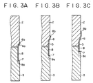
- the helical taper section 6a descends towards the departing position in parallel with the helical tape lead 7 in a region between a position shown in Figure 3B and a position shown in Figure 3A.
- Another section of the taper surface 6 between the position shown in Figure 3B and a position shown in Figure 3C extends in a plane perpendicular to the axis of the upper drum 2, namely the rotational axis of the rotary heads 4.
- the upper drum 2 is provided at its lower end with a helical taper surface 6 extending in parallel to a helical tape lead 7 formed in the circumference of the lower drum 3 over the entire arc ⁇ 1 of contact between the magnetic tape 8 and the rotary head drum unit.
- the portion of the upper drum 2 provided with the helical taper surface 6 descends towards the lead-out region in parallel with the tape lead 7 of the lower drum 3 as shown in Figures 6A to 6C.
- the upper portion of the magnetic tape 8 near its upper edge 8b slides along the helical taper section 6a or the helical taper surface 6 parallel to the helical tape lead 7 in the lead-out region 11, so that the helical taper section 6a or the helical taper surface 6 is able to bias the magnetic tape 8 securely towards the helical tape lead 7 such that the lower edge 8a of the magnetic tape 8 is guided by the helical tape lead 7 to secure the magnetic tape 8 for stable running.
- the upper edge 8b of the magnetic tape 8 is in sliding contact with the helical taper section 6a or the helical taper surface 6 in the lead-out region 11, the upper portion of the magnetic tape 8 near its upper edge 8b is continually kept taut while the magnetic tape 8 is running, so that faulty contact between the magnetic tape 8 and the rotary heads 4 due to slack in the upper portion of the magnetic tape 8 near its upper edge 8b can be obviated. Since the helical taper section 6a in contact with the upper portion of the magnetic tape 8 near its upper edge 8b varies gradually with respect to the radial direction, the helical taper section 6a does not affect the contact between the magnetic tape 8 and the rotary head 4 at all adversely.
Description
- This invention relates to rotary head drum units having stationary upper and lower drums, and which may be applied to recording/reproducing apparatus such as a video tape recorder (VTR).
- The present applicant has previously proposed a rotary head drum unit for a VTR in Japanese Utility Model Laid-Open (Kokai) No. JP-A-62-73337. As shown in Figures 7 to 10C of the accompanying drawings, in this previously-proposed rotary head drum unit, a plurality of rotary heads 4 (such as magnetic heads) are positioned for rotation between an
upper drum 2 and alower drum 3 fixedly connected to each other by a drum post 1. A rotary flange (not shown) for rotatively driving therotary heads 4 is disposed coaxially with theupper drum 2 and thelower drum 3. The diameter of theupper drum 2 is greater than that of thelower drum 3. Ataper surface 6 is formed in the lower portion of theupper drum 2, and a reducedportion 5 of a diameter equal to that of thelower drum 3 is formed contiguously with the lower end of thetaper surface 6. Thetaper surface 6 and the reducedportion 5 are symmetrical with respect to the axis of theupper drum 2. A helical tape guiding surface, hereinafter referred to as ahelical tape lead 7, is formed in the circumference of thelower drum 3. Amagnetic tape 8 is guided by a lead-outguide 9 and a lead-inguide 10 so as to extend helically across theupper drum 2 and thelower drum 3 with thelower edge 8a of thetape 8 guided by thetape lead 7. The arc ϑ₁ of contact between the rotary head drum unit and themagnetic tape 8 may, for example, be about 188° and the data recording angle ϑ₂ of therotary heads 4 may, for example, be about 178°. - When recording data on or reproducing recorded data from the
magnetic tape 8 by rotating therotary heads 4 in the direction of an arrow b at a high rotating speed while themagnetic tape 8 runs in the direction of an arrow a, themagnetic tape 8 is biased downwardly by thetaper surface 6 of theupper drum 2 so that thelower edge 8a of themagnetic tape 8 slides along thetape lead 7 as themagnetic tape 8 runs. - As is apparent from Figures 10A, 10B and 10C showing longitudinal sections of the rotary head drum unit at different angular positions, since a portion of the
upper drum 2 having thetaper surface 6 extends in a plane perpendicular to the axis of theupper drum 2, the vertical position of themagnetic tape 8 moves downwards relative to thetaper surface 6 as the magnetic tape advances. Since the portion of theupper drum 2 having thetaper surface 6 extends in a plane perpendicular to the axis of theupper drum 2, whereas themagnetic tape 8 runs obliquely to thetaper surface 6, theupper edge 8b of themagnetic tape 8 deviates completely downwardly away from thetaper surface 6 in a lead-out region 11 near a departing position at which themagnetic tape 8 departs from the rotary head drum unit. Accordingly, thetaper surface 6 is unable to urge themagnetic tape 8 downwardly in the lead-out region 11 and, consequently, thelower edge 8a of themagnetic tape 8 is liable to separate in an upward direction from thetape lead 7 as a result of which themagnetic tape 8 is then liable to run unstably. In the lead-out region 11 near the departing position, a portion of themagnetic tape 8 near theupper edge 8b is liable to be slack and, consequently, themagnetic tape 8 is liable to be in faulty contact with therotary heads 4. - According to one aspect of the invention there is provided a rotary head drum unit for a recording/reproducing apparatus, the unit comprising:
a stationary lower drum provided at its circumference with a helical tape lead for guiding the lower edge of a magnetic tape;
a stationary upper drum fixedly connected to the lower drum, and provided at its lower end with a taper surface within the contact region between tape and upper drum so as to bias the tape towards the tape lead; and
rotary heads between the upper and lower drums;
characterised in that the taper surface of the upper drum has a helical taper section extending substantially in parallel with the helical tape lead of the lower drum in a lead-out region near a departing position at which the magnetic tape departs from the lower drum. - In another aspect of the invention, a rotary head drum unit comprises a stationary upper drum provided at its lower end with a taper surface for biasing a magnetic tape downwardly, a stationary lower drum provided at its circumference with a helical tape lead to guide the lower edge of a tape helically extended across the upper and lower drums, and rotary heads positioned between the upper and lower drums, characterised in that at least a portion of the taper surface of the upper drum in a lead-out region near a departing position at which the magnetic tape departs from the rotary head drum unit is extended helically substantially in parallel to the helical tape lead.
- Such a rotary head drum unit is able to make a tape run with its upper edge sliding along the taper surface of the upper drum even in the lead-out region, so that the taper surface is able to bias the tape securely towards the tape lead of the lower drum even in the lead-out region. Since the upper portion of the tape near its upper edge is continually in sliding contact with the taper surface of the upper drum even in the lead-out region, the upper portion of the tape is kept taut while the tape runs along the rotary head drum unit.
- The invention will now be described by way of example with reference to the accompanying drawings, throughout which like parts are referred to by like references, and in which:
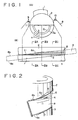
- Figure 1A is a plan view of a rotary head drum unit according to a preferred embodiment of the present invention;
- Figure 1B is an opened-out side view development of the circumference of the rotary head drum unit of Figure 1A;
- Figure 2 is a fragmentary perspective view of a portion of the rotary head drum unit of Figures 1A and 1B in the vicinity of a lead-out region near a departing position where a magnetic tape departs from the rotary head drum unit;
- Figures 3A, 3B and 3C are sectional views taken on lines IIIA-IIIA, IIIB-IIIB and IIIC-IIIC, respectively, in Figure 1B;
- Figure 4A is a plan view of a modification of the rotary head drum unit shown in Figure 1A;
- Figure 4B is an opened-out side view development of the circumference of the rotary head drum unit of Figure 4A;
- Figure 5 is a fragmentary perspective view of a portion of the rotary head drum unit of Figures 4A and 4B in the vicinity of the lead-out region;
- Figures 6A, 6B and 6C are sectional views taken on lines VIA-VIA, VIB-VIB and VIC-VIC, respectively, in Figure 4B;
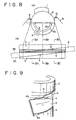
- Figure 7 is a front view of a known rotary head drum unit;
- Figure 8A is a plan view of the rotary head drum unit of Figure 7;
- Figure 8B is an opened-out side view development of the circumference of the rotary head drum unit of Figure 7;
- Figure 9 is a fragmentary perspective view of a portion of the rotary head drum unit of Figure 7 in the vicinity of a lead-out region; and
- Figures 10A, 10B and 10C are sectional views taken on lines XA-XA, XB-XB and XC-XC, respectively, in Figure 8B.
- A rotary head drum unit according to a preferred embodiment of the present invention will be described hereinafter as applied to a VTR with reference to Figures 1A to 6C, in which parts similar or corresponding to those shown in Figures 7 to 10C are denoted by the same reference characters, and detailed description of these parts will be omitted to avoid duplication.
- Referring to Figures 1A to 3C, a rotary head drum unit has an
upper drum 2 provided at its lower end with ataper surface 6 having ahelical taper section 6a in a lead-out region 11 near a departing position at which amagnetic tape 8 departs from the rotary head drum unit. Thehelical taper section 6a extends in parallel to ahelical tape lead 7 formed in the circumference of alower drum 3. Thehelical taper section 6a descends towards the departing position in parallel with thehelical tape lead 7 in a region between a position shown in Figure 3B and a position shown in Figure 3A. Another section of thetaper surface 6 between the position shown in Figure 3B and a position shown in Figure 3C extends in a plane perpendicular to the axis of theupper drum 2, namely the rotational axis of therotary heads 4. - In a rotary head drum unit according to a modification shown in Figures 4A to 6C, the
upper drum 2 is provided at its lower end with ahelical taper surface 6 extending in parallel to ahelical tape lead 7 formed in the circumference of thelower drum 3 over the entire arc ϑ₁ of contact between themagnetic tape 8 and the rotary head drum unit. The portion of theupper drum 2 provided with thehelical taper surface 6 descends towards the lead-out region in parallel with thetape lead 7 of thelower drum 3 as shown in Figures 6A to 6C. - In either the rotary head drum unit shown in Figure 1A or the rotary head drum unit shown in Figure 4A, the upper portion of the
magnetic tape 8 near itsupper edge 8b slides along thehelical taper section 6a or thehelical taper surface 6 parallel to thehelical tape lead 7 in the lead-out region 11, so that thehelical taper section 6a or thehelical taper surface 6 is able to bias themagnetic tape 8 securely towards thehelical tape lead 7 such that thelower edge 8a of themagnetic tape 8 is guided by thehelical tape lead 7 to secure themagnetic tape 8 for stable running. - Since the
upper edge 8b of themagnetic tape 8 is in sliding contact with thehelical taper section 6a or thehelical taper surface 6 in the lead-out region 11, the upper portion of themagnetic tape 8 near itsupper edge 8b is continually kept taut while themagnetic tape 8 is running, so that faulty contact between themagnetic tape 8 and therotary heads 4 due to slack in the upper portion of themagnetic tape 8 near itsupper edge 8b can be obviated. Since thehelical taper section 6a in contact with the upper portion of themagnetic tape 8 near itsupper edge 8b varies gradually with respect to the radial direction, thehelical taper section 6a does not affect the contact between themagnetic tape 8 and therotary head 4 at all adversely.
Claims (5)
- A rotary head drum unit for a recording/reproducing apparatus, the unit comprising:
a stationary lower drum (3) provided at its circumference with a helical tape lead (7) for guiding the lower edge (8a) of a magnetic tape (8);
a stationary upper drum (2) fixedly connected to the lower drum (3), and provided at its lower end with a taper surface (6) within the contact region between tape and upper drum so as to bias the tape towards the tape lead; and
rotary heads (4) between the upper and lower drums (2,3);
characterised in that the taper surface (6) of the upper drum (2) has a helical taper section (6a) extending substantially in parallel with the helical tape lead (7) of the lower drum (3) in a lead-out region (11) near a departing position at which the magnetic tape (8) departs from the lower drum (3). - A rotary head drum unit according to claim 1, wherein the diameter of the upper drum (2) is greater than that of the lower drum (3), and the diameter of the lower end of the taper surface (6) is equal to that of the lower drum (3).
- A rotary head drum unit according to claim 1 or claim 2, wherein the helical taper section (6a) extends over one circumferential part of a contact region between the magnetic tape (8) and the upper drum (2,3), the taper surface (6) over the other part of the contact region extending in a plane perpendicular to the rotational axis of the rotary heads (4).
- A rotary head drum unit according to claim 1 or claim 2, wherein the helical taper section (6a) extends in circumferential direction over the contact region between the magnetic tape (8) and the upper drum (2,3).
- A rotary head drum unit according to any one of the preceding claims, wherein the upper and lower drums (2,3) are fixedly disposed in a recording/reproducing apparatus.
Applications Claiming Priority (2)
| Application Number | Priority Date | Filing Date | Title |
|---|---|---|---|
| JP182250/90 | 1990-07-10 | ||
| JP2182250A JPH0469851A (en) | 1990-07-10 | 1990-07-10 | Rotary head drum device |
Publications (3)
| Publication Number | Publication Date |
|---|---|
| EP0466441A2 EP0466441A2 (en) | 1992-01-15 |
| EP0466441A3 EP0466441A3 (en) | 1992-04-22 |
| EP0466441B1 true EP0466441B1 (en) | 1995-12-20 |
Family
ID=16114972
Family Applications (1)
| Application Number | Title | Priority Date | Filing Date |
|---|---|---|---|
| EP91306192A Expired - Lifetime EP0466441B1 (en) | 1990-07-10 | 1991-07-08 | Rotary head drum units |
Country Status (5)
| Country | Link |
|---|---|
| US (1) | US5237478A (en) |
| EP (1) | EP0466441B1 (en) |
| JP (1) | JPH0469851A (en) |
| KR (1) | KR100210345B1 (en) |
| DE (1) | DE69115580T2 (en) |
Families Citing this family (1)
| Publication number | Priority date | Publication date | Assignee | Title |
|---|---|---|---|---|
| JP3233477B2 (en) * | 1993-03-02 | 2001-11-26 | 株式会社日立製作所 | Rotary magnetic recording / reproducing device |
Family Cites Families (8)
| Publication number | Priority date | Publication date | Assignee | Title |
|---|---|---|---|---|
| DE3118241A1 (en) * | 1981-05-08 | 1982-11-25 | Licentia Patent-Verwaltungs-Gmbh, 6000 Frankfurt | Drive mechanism for a video recorder with helical track recording |
| JPS58148757A (en) * | 1982-02-28 | 1983-09-03 | 松下電工株式会社 | Manufacture of veneer with one-surface resin layer |
| JPS637955Y2 (en) * | 1984-12-24 | 1988-03-09 | ||
| JPS6310312A (en) * | 1986-07-01 | 1988-01-16 | Toshiba Corp | Magnetic recording and reproducing device |
| US4833562A (en) * | 1987-06-03 | 1989-05-23 | Hitachi Ltd. | Rotary magnetic head cylinder device for suppressing vibrations ofa magnetic tape |
| JPS6430050A (en) * | 1987-07-24 | 1989-01-31 | Hitachi Ltd | Rotary magnetic head device |
| DE3802276A1 (en) * | 1988-01-27 | 1989-08-03 | Grundig Emv | Magnetic tape apparatus |
| JPH0786971B2 (en) * | 1989-01-12 | 1995-09-20 | シャープ株式会社 | Rotating head type magnetic recording / reproducing device |
-
1990
- 1990-07-10 JP JP2182250A patent/JPH0469851A/en active Pending
-
1991
- 1991-07-08 DE DE69115580T patent/DE69115580T2/en not_active Expired - Fee Related
- 1991-07-08 EP EP91306192A patent/EP0466441B1/en not_active Expired - Lifetime
- 1991-07-09 US US07/727,435 patent/US5237478A/en not_active Expired - Fee Related
- 1991-07-10 KR KR1019910011657A patent/KR100210345B1/en not_active IP Right Cessation
Also Published As
| Publication number | Publication date |
|---|---|
| US5237478A (en) | 1993-08-17 |
| EP0466441A2 (en) | 1992-01-15 |
| KR100210345B1 (en) | 1999-07-15 |
| DE69115580T2 (en) | 1996-05-02 |
| DE69115580D1 (en) | 1996-02-01 |
| JPH0469851A (en) | 1992-03-05 |
| EP0466441A3 (en) | 1992-04-22 |
Similar Documents
| Publication | Publication Date | Title |
|---|---|---|
| US4891726A (en) | Rotary magnetic head and guide drum assembly with reduce mounting height | |
| EP0466441B1 (en) | Rotary head drum units | |
| US3939494A (en) | Resilient tape guide assembly for tape recording and/or reproducing apparatus | |
| US4100585A (en) | Magnetic-tape guide arrangement | |
| US5303106A (en) | Rotary-head drum device for guiding a tape therearound | |
| US5008769A (en) | Rotary head type magnetic recording/reproducing device | |
| US4757408A (en) | Magnetic recording and/or reproducing apparatus | |
| US5798893A (en) | Head drum assembly for use in a video cassette recorder | |
| US5282096A (en) | Magnetic recording and playback apparatus | |
| EP0391728B1 (en) | Magnetic tape helical recording and playback apparatus adapted for postrecording | |
| GB2308723A (en) | Vertically moving guide posts/rollers adjust video tracking | |
| US5623385A (en) | Rotary scanning device | |
| KR900004864Y1 (en) | Magnetic head of hard disc driver | |
| KR200339958Y1 (en) | Arm tension assembly of tape recorder | |
| US5661622A (en) | Rotary magnetic head cylinder device for reduced vibration and proper head/type alignment | |
| JPH0612637A (en) | Rotary magnetic head | |
| KR0155694B1 (en) | Head drum tape recorder | |
| KR100359073B1 (en) | Head drum assembly | |
| KR100513827B1 (en) | head-drum assembly for magnetic recording/reading apparatus | |
| KR0133185Y1 (en) | Bulge structure of head drum | |
| JPH04289510A (en) | Rotary magnetic head device | |
| KR920006907Y1 (en) | Drum with control head | |
| KR0176562B1 (en) | Position detector of magnetic head in a tape recorder | |
| EP0605056B1 (en) | Magnetic-tape apparatus and magnetic-head unit suitable for use in the magnetic-tape apparatus | |
| JP2618043B2 (en) | Magnetic tape unit |
Legal Events
| Date | Code | Title | Description |
|---|---|---|---|
| PUAI | Public reference made under article 153(3) epc to a published international application that has entered the european phase |
Free format text: ORIGINAL CODE: 0009012 |
|
| AK | Designated contracting states |
Kind code of ref document: A2 Designated state(s): DE FR GB |
|
| PUAL | Search report despatched |
Free format text: ORIGINAL CODE: 0009013 |
|
| AK | Designated contracting states |
Kind code of ref document: A3 Designated state(s): DE FR GB |
|
| 17P | Request for examination filed |
Effective date: 19920925 |
|
| 17Q | First examination report despatched |
Effective date: 19950307 |
|
| GRAA | (expected) grant |
Free format text: ORIGINAL CODE: 0009210 |
|
| AK | Designated contracting states |
Kind code of ref document: B1 Designated state(s): DE FR GB |
|
| REF | Corresponds to: |
Ref document number: 69115580 Country of ref document: DE Date of ref document: 19960201 |
|
| ET | Fr: translation filed | ||
| PLBE | No opposition filed within time limit |
Free format text: ORIGINAL CODE: 0009261 |
|
| STAA | Information on the status of an ep patent application or granted ep patent |
Free format text: STATUS: NO OPPOSITION FILED WITHIN TIME LIMIT |
|
| 26N | No opposition filed | ||
| PGFP | Annual fee paid to national office [announced via postgrant information from national office to epo] |
Ref country code: DE Payment date: 20010702 Year of fee payment: 11 |
|
| PGFP | Annual fee paid to national office [announced via postgrant information from national office to epo] |
Ref country code: GB Payment date: 20010704 Year of fee payment: 11 |
|
| PGFP | Annual fee paid to national office [announced via postgrant information from national office to epo] |
Ref country code: FR Payment date: 20010712 Year of fee payment: 11 |
|
| REG | Reference to a national code |
Ref country code: GB Ref legal event code: IF02 |
|
| PG25 | Lapsed in a contracting state [announced via postgrant information from national office to epo] |
Ref country code: GB Free format text: LAPSE BECAUSE OF NON-PAYMENT OF DUE FEES Effective date: 20020708 |
|
| PG25 | Lapsed in a contracting state [announced via postgrant information from national office to epo] |
Ref country code: DE Free format text: LAPSE BECAUSE OF NON-PAYMENT OF DUE FEES Effective date: 20030201 |
|
| GBPC | Gb: european patent ceased through non-payment of renewal fee |
Effective date: 20020708 |
|
| PG25 | Lapsed in a contracting state [announced via postgrant information from national office to epo] |
Ref country code: FR Free format text: LAPSE BECAUSE OF NON-PAYMENT OF DUE FEES Effective date: 20030331 |
|
| REG | Reference to a national code |
Ref country code: FR Ref legal event code: ST |