EP0466255A2 - Verfahren zum Bestimmen der Bohrbedingungen in Verbindung mit dem Bohren einer Formation mittels eines Fräsbohrmeissels - Google Patents
Verfahren zum Bestimmen der Bohrbedingungen in Verbindung mit dem Bohren einer Formation mittels eines Fräsbohrmeissels Download PDFInfo
- Publication number
- EP0466255A2 EP0466255A2 EP91201708A EP91201708A EP0466255A2 EP 0466255 A2 EP0466255 A2 EP 0466255A2 EP 91201708 A EP91201708 A EP 91201708A EP 91201708 A EP91201708 A EP 91201708A EP 0466255 A2 EP0466255 A2 EP 0466255A2
- Authority
- EP
- European Patent Office
- Prior art keywords
- bit
- drilling
- efficiency
- values
- drillbit
- Prior art date
- Legal status (The legal status is an assumption and is not a legal conclusion. Google has not performed a legal analysis and makes no representation as to the accuracy of the status listed.)
- Granted
Links
- 238000005553 drilling Methods 0.000 title claims abstract description 131
- 238000000034 method Methods 0.000 title claims abstract description 65
- 230000015572 biosynthetic process Effects 0.000 title claims abstract description 34
- 238000005755 formation reaction Methods 0.000 claims abstract description 32
- 230000008569 process Effects 0.000 claims abstract description 18
- 230000035515 penetration Effects 0.000 claims abstract description 12
- 230000008859 change Effects 0.000 claims abstract description 8
- 239000011435 rock Substances 0.000 claims description 55
- 238000005520 cutting process Methods 0.000 claims description 44
- 238000010586 diagram Methods 0.000 claims description 18
- 239000011148 porous material Substances 0.000 claims description 10
- 239000012530 fluid Substances 0.000 claims description 6
- 238000001514 detection method Methods 0.000 claims description 2
- 235000002639 sodium chloride Nutrition 0.000 description 14
- 239000010442 halite Substances 0.000 description 11
- 230000009471 action Effects 0.000 description 10
- 230000004044 response Effects 0.000 description 9
- 230000005251 gamma ray Effects 0.000 description 8
- 238000005259 measurement Methods 0.000 description 8
- 238000004458 analytical method Methods 0.000 description 6
- 235000019738 Limestone Nutrition 0.000 description 4
- 238000004364 calculation method Methods 0.000 description 4
- 230000007423 decrease Effects 0.000 description 4
- 239000006028 limestone Substances 0.000 description 4
- 229910003460 diamond Inorganic materials 0.000 description 3
- 239000010432 diamond Substances 0.000 description 3
- 230000000694 effects Effects 0.000 description 3
- 238000011065 in-situ storage Methods 0.000 description 3
- 230000003993 interaction Effects 0.000 description 3
- 238000012417 linear regression Methods 0.000 description 3
- 150000003839 salts Chemical class 0.000 description 3
- 238000004441 surface measurement Methods 0.000 description 3
- 238000012360 testing method Methods 0.000 description 3
- 235000015076 Shorea robusta Nutrition 0.000 description 2
- 244000166071 Shorea robusta Species 0.000 description 2
- 239000003082 abrasive agent Substances 0.000 description 2
- 230000001427 coherent effect Effects 0.000 description 2
- UONOETXJSWQNOL-UHFFFAOYSA-N tungsten carbide Chemical compound [W+]#[C-] UONOETXJSWQNOL-UHFFFAOYSA-N 0.000 description 2
- 229910052925 anhydrite Inorganic materials 0.000 description 1
- OSGAYBCDTDRGGQ-UHFFFAOYSA-L calcium sulfate Chemical compound [Ca+2].[O-]S([O-])(=O)=O OSGAYBCDTDRGGQ-UHFFFAOYSA-L 0.000 description 1
- 238000004140 cleaning Methods 0.000 description 1
- 229910017052 cobalt Inorganic materials 0.000 description 1
- 239000010941 cobalt Substances 0.000 description 1
- GUTLYIVDDKVIGB-UHFFFAOYSA-N cobalt atom Chemical compound [Co] GUTLYIVDDKVIGB-UHFFFAOYSA-N 0.000 description 1
- 230000003247 decreasing effect Effects 0.000 description 1
- 230000003467 diminishing effect Effects 0.000 description 1
- 238000006073 displacement reaction Methods 0.000 description 1
- 238000002474 experimental method Methods 0.000 description 1
- 230000014509 gene expression Effects 0.000 description 1
- 230000002706 hydrostatic effect Effects 0.000 description 1
- 238000007373 indentation Methods 0.000 description 1
- 238000009533 lab test Methods 0.000 description 1
- 239000000463 material Substances 0.000 description 1
- 229910052751 metal Inorganic materials 0.000 description 1
- 239000002184 metal Substances 0.000 description 1
- 239000003129 oil well Substances 0.000 description 1
- 230000000704 physical effect Effects 0.000 description 1
- 238000003825 pressing Methods 0.000 description 1
- 238000000611 regression analysis Methods 0.000 description 1
- 238000010008 shearing Methods 0.000 description 1
- 230000007480 spreading Effects 0.000 description 1
- 238000003892 spreading Methods 0.000 description 1
- 238000003786 synthesis reaction Methods 0.000 description 1
- 230000009897 systematic effect Effects 0.000 description 1
- 230000007704 transition Effects 0.000 description 1
- 229910052721 tungsten Inorganic materials 0.000 description 1
- 238000012795 verification Methods 0.000 description 1
Images


Classifications
-
- E—FIXED CONSTRUCTIONS
- E21—EARTH OR ROCK DRILLING; MINING
- E21B—EARTH OR ROCK DRILLING; OBTAINING OIL, GAS, WATER, SOLUBLE OR MELTABLE MATERIALS OR A SLURRY OF MINERALS FROM WELLS
- E21B49/00—Testing the nature of borehole walls; Formation testing; Methods or apparatus for obtaining samples of soil or well fluids, specially adapted to earth drilling or wells
- E21B49/003—Testing the nature of borehole walls; Formation testing; Methods or apparatus for obtaining samples of soil or well fluids, specially adapted to earth drilling or wells by analysing drilling variables or conditions
-
- E—FIXED CONSTRUCTIONS
- E21—EARTH OR ROCK DRILLING; MINING
- E21B—EARTH OR ROCK DRILLING; OBTAINING OIL, GAS, WATER, SOLUBLE OR MELTABLE MATERIALS OR A SLURRY OF MINERALS FROM WELLS
- E21B12/00—Accessories for drilling tools
- E21B12/02—Wear indicators
-
- E—FIXED CONSTRUCTIONS
- E21—EARTH OR ROCK DRILLING; MINING
- E21B—EARTH OR ROCK DRILLING; OBTAINING OIL, GAS, WATER, SOLUBLE OR MELTABLE MATERIALS OR A SLURRY OF MINERALS FROM WELLS
- E21B44/00—Automatic control systems specially adapted for drilling operations, i.e. self-operating systems which function to carry out or modify a drilling operation without intervention of a human operator, e.g. computer-controlled drilling systems; Systems specially adapted for monitoring a plurality of drilling variables or conditions
Definitions
- the present invention relates to a method of determining the drilling conditions associated with the drilling of a formation with a rotating drillbit.
- the invention allows the determination of characteristics of the formation and/or the drillbit.
- the rotary drillbits concerned by the invention can generally be referred to as "drag bits", which are composed of fixed cutters mounted at the surface of a bit body.
- a well-known type of drag bit used in the oilfield industry is the polycrystalline diamond compact (PDC) drilling bit.
- PDC rock drilling bit consists of a number of polycrystalline diamond compacts bonded on tungsten carbide support studs, which form the bit cutters rigidly mounted at the surface of the bit body.
- This type of drillbit is for example described in European Patent Number 0,193,361.
- the present invention aims at solving this problem and proposes a method of determining the drilling conditions when drilling an underground formation or a rock with a rotary drillbit of the drag bit type.
- formation and “rock” are used interchangeably to designate an underground formation or a rock sample.
- the characteristics which are determined relate to the formation itself e.g. the "intrinsic specific energy” ⁇ (as hereinafter defined) and the internal friction angle ⁇ of the rock, to the drilling process e.g. the detection of bit balling and the drilling efficiency and x , to a change in the lithology while drilling, and to the drillbit itself e.g. state of wear and efficiency.
- the present invention relates to a method of determining the drilling conditions associated with the drilling of a borehole with a rotary drag bit through subterranean formations corresponding to particular lithologies, comprising the steps of:
- the invention also relates to a method of determining the efficiency of at least one drag drillbit comprising the steps of:
- the ratio of the variation of E over the corresponding variation of S is advantageously determined as this is related to the product of a bit constant ⁇ and a friction coefficient ⁇ .
- the present invention is based on a model describing the interaction of a drag drillbit with the formation being drilled. To better understand the invention, the meaning of the parameters being determined is given herebelow in the Technical Background.
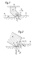
- Figure 1 represents schematically a cutter 10 fixed at the surface of the body 12 of a drillbit.
- the drillbit comprises a plurality of cutters identical to cutter 10, located on several circumferential rows centred around the bit rotational axis.
- Each cutter is composed of a stud having a flat cutting face 14 on which a layer of hard abrasive material is deposited.
- the hard abrasive material is a synthetic polycrystalline diamond bonded during synthesis onto a tungsten carbide/cobalt metal support.
- a model describing the action of a single cutter, first perfectly sharp and then blunt is considered and extrapolated to a model of a drill bit.
- Sharp cutter In Figure 1, a perfectly sharp cutter 10 traces a groove 16 of constant cross-sectional area s on a horizontal rock surface 18. It is assumed that the cutter is under pure kinematic control, ie the cutter is imposed to move at a prescribed horizontal velocity in the direction indicated by the arrow 20, with a zero vertical velocity and with a constant depth of cut h. As a result of the cutting action, a force F° develops on the cutter.
- F c n and F c s denote the force components that are respectively normal and parallel to the rock surface, F° being the product of these forces.
- F c n and F c s are both proportional to the cross-sectional area s of the cut and are given by: where ⁇ is defined as the intrinsic specific energy and is the ratio of the vertical to the horizontal force acting on the cutting face.
- the quantity ⁇ has the same dimension as a stress (a convenient unit for ⁇ is the MPa).
- the intrinsic specific energy ⁇ represents the amount of energy spent to cut a unit volume of rock by a pure cutting action with no frictional action.
- the intrinsic specific energy depends on the mechanical and physical properties of the rock (cohesion, internal friction angle, porosity, etc.), the hydrostatic pressure of the drilling fluid exerted on the rock at the level of the drillbit and the rock pore pressure, the backrake angle 0 of the cutter, and the frictional angle at the interface rock/cutting face.
- the backrake angle 0, as illustrated in Figure 1 is defined as the angle that the cutting face 14 makes with the normal to the surface of the rock and the friction angle ⁇ is the angle that the force F° makes with the normal to the cutting face.
- the cutter force F is now decomposed into two vectorial components, F° which is transmitted by the cutting face 14, and F f acting across the wear flat 22. It is assumed that the cutting components F c n and F c s obeys the relations (1) and (2) for a perfectly sharp cutter. It is further assumed that a frictional process is taking place at the interface between the wearflat 22 and the rock; thus the components F f n and F f s are related where ⁇ , is a coefficient of friction.
- the horizontal force component F s is equal to F c s + Ff
- the vertical force component F n is equal to F c n + F f n .
- the horizontal component F s can be expressed as Writing F f n as F n - Fg and using equation (2), this equation becomes Two new quantities are now introduced: the specific energy E defined as and the drilling strength S Both quantities, specific energy E and intrinsic specific energy E , have obviously the same general meaning. However, E represents the energy spent by unit volume of rock cut, irrespective of the fact that the cutter is sharp or worn, when cutting and frictional contact processes are taking place simultaneously, while E is meaningful only for the cutting action, with no dissipation of energy in a frictional contact process.
- the action of a single cutter described above can be generalised to a model describing the action of a drillbit which is based on the fact that two processes, cutting and frictional contact, characterize the bit-rock interaction.
- the torque T and weight-on-bit W can thus be decomposed into two components, i.e. c and f referring to cutting and friction respectively.
- a drillbit constant ⁇ intervenes in equation (10) which then becomes and equation (11) becomes with
- ⁇ is a bit constant, which depends on the bit profile, the shape of the cutting edge, the number of cutters and their position on the bit.
- the magnitude of ⁇ is greater than 1.
- the theoretical range of variation of ⁇ is between 1 and j .
- the lower bound is obtained by assimilating the bit to a single blade, the upper one to a frictional pad.
- the parameter ⁇ is the friction coefficient defined by equation (4).
- the internal friction angle ⁇ is an important and well-known characteristic of a rock.
- the drilling states must therefore correspond to E ⁇ or equivalently S ⁇ .
- the threshold value W! depends on the wear state of the bit, the rock being drilled, the mud pressure, etc; it can expressed as where ⁇ * is the contact strength or hardness (function of the rock, mud pressure, pore pressure,...) and ⁇ * is the fully mobilized contact length, characteristic of a certain wear state of the bit.
- W f * the contact component of the weight-on-bit, W f increases progressively until it reaches the threshold value W f * (the increase of W f is due to a combination of an increase of the contact length ⁇ and the contact stress ⁇ ).
- the drilling efficiency ⁇ which gives a relative measure of the energy dissipated in frictional contact at the bit, is seen to be sensitive to the contact length and the contact stress. It is actually useful to determine directly the product ⁇ , which provides a combined measure of the wear state of the bit and the strength of the rock. This product is calculated according to
- the drilling specific energy E and the drilling strengths are periodically calculated so as to derive valuable information on the formation and the drillbit.
- the drilling specific energy E and the drilling strength S are calculated as follows:
- the symbol a designates the radius of the bit and 6 is the depth of cut per revolution calculated as Both E and S have the dimension of a stress (Force per unit area); a convenient unit for E and S is the MPa (N/mm 2 ). Under normal operating conditions of a PDC bit, E ⁇ 1,000 MPa, and S ⁇ 2,000 MPa.
- the weight applied on the bit W, the torque T, the penetration rate v and the rotational speed ⁇ are measured periodically so as to acquire sets of measurements, for example one data set per 30 centimetres drilled. From each set (W, T, v, ⁇ ), the drilling specific energy E and the drilling strength S are computed according to equations (26) and (27). Notation E i and S is used hereafter to designate the value of the specific energy and drilling strength corresponding to the acquisition number i of a particular set of measurements. The pair (E i , S i ) is thus representative of the depth interval corresponding to the acquisition number i.
- T, W, v and ⁇ can be measured at the surface or at the bottom of the hole by conventional equipment used now commercially in the drilling industry.
- the torque T could be obtained by using the torquemeter described in US Patent 4,471,663; the weight-on-bit W by using the method described in US Patent 4,886,129; and the penetration rate v by using the method described in US Patent 4,843,875.
- an MWD tool is used for measuring the torque T and the weight-on-bit W.
- the apparatus described in US Patent 3,855,857 or 4,359,898 could be used for measuring the torque T and the weight-on-bit W. Measurements are made periodically at a frequency which could vary between 10 centimetres to 1 meter of the formation being drilled or between 1 to 3 minutes. It should be noted that the data used for the determination of E and S can correspond to average values of the measured parameters over a certain period of time or drilled depth. This is more especially true for the penetration rate v and the rotational speed ⁇ .
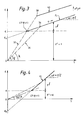
- a diagram representing the values of E versus S is built by plotting each pair (E i , S i ) calculated from one set of measurements on a diagram representing E versus S.
- FIG 3 represents the diagram E-S. Equation (9) is represented by a straight line FL, called friction line, of slope ⁇ . ⁇ (which is equal to ⁇ / ⁇ in accordance with equation (15)).
- the friction line FL has been represented for values of smaller than 1, which covers the general case.
- Admissible states of the drilling response of a drag bit are represented by all the points on the friction line FL.
- This quantity x gives an indication of the efficiency ⁇ of the drilling process at the particular point (S i , E i ) (equation (18)) and is particularly interesting to obtain when the determination of the cutting point CP is not easy and therefore when ⁇ and are difficult to determine.
- the intrinsic specific energy ⁇ and the contact strength a are parameters that depend significantly on the mud pressure p" and the pore pressure pP. E and a increase with increasing mud pressure p h but decrease with increasing pore pressure pP. All the other quantities, ⁇ , ⁇ and y are practically independent of the mud pressure.
- an increase of the mud pressure causes an increase of the intrinsic specific energy ⁇ and therefore causes the cutting point CP to move up on the line 32 to point 38 (line 32 is the locus of the cutting points), displacing with it the friction line FL to the parallel friction line 40 indicated in Figure 3.
- a variation of pore pressure pP of the formation produces the same effect, ie a parallel displacement of the friction line FL.
- FIG. 4 is the diagram E-S, representing equation (12) but now with ⁇ >1 ( Figure 3 was for ⁇ 1).
- Eo is negative, which means that if the weight-on-bit W is kept constant, the torque T increases with a decreasing drilling efficiency.
- the states of diminishing efficiency are characterised by increasing values of the slope x.
- Another step of the invention involves the identification of the various linear clusters in the diagram E-S. Since the drilling fluid pressure and pore pressure evolve in general slowly, each cluster corresponds to a different lithology. Some confidence in the correct identification of a cluster can be gained by checking whether the cluster is indeed composed of sequential pairs (E ; , S ; ). Exceptions exist however which defeat this verification procedure: for example a sequence of alternating beds cause the drilling response to jump between two clusters, every few points. When the bit is very sharp, the cluster of points in the E-S plot will be compact and close to the cutting point CP because most of the drilling energy is used for cutting the rock and very little is dissipated in friction.
- the cluster will migrate towards the right on the friction line and will also stretch because more and more energy is dissipated in friction.
- the effect of wear on the drilling response of drag bits is however very much controlled by the strength of the rock being drilled.
- the drilling response of a worn bit is characterised by greater fluctuations of the torque and rate of penetration, and generally by a lower efficiency.
- these characteristics correspond to a cloud of points which is more elongated and positioned further away from the optimal operating point of the case of hard rock.
- bit balling tends to occur in "soft" formations, that are characterized by rather small values of the friction coefficient ⁇ (typically less than 0.5) but relatively large values of the intrinsic specific energy E , while the influence of bit wear on the drilling response will be more marked in "hard” formations, that are generally characterized by higher values of ⁇ (typically above 0.5) but relatively small values of ⁇ .
- y is not known, it can generally be set to 1. This value which represents the theoretical lower bound on y is unlikely to be more than 20% different from the true value of y. Setting y to 1 will result in an overestimation of ⁇ .
- the next step is to identify the "lower-left” (LL) point of the cluster which would correspond to the cutting point CP if the drilling efficiency was equal to 1.
- the point LL corresponds to the best drilling efficiency achieved during the segment of bit run represented by the data cluster. Ideally this point can be unambiguously identified: it corresponds to the minimum drilling strength and specific energy of the cluster and it is close to the friction line calculated by least squares from the drilling data. If some ambiguity exists, eg the "left-most" point corresponding to the minimum S is not the same as the "lowest" one corresponding to the minimum E i , then the point closest to the regression line is selected.
- the quality of E * as an estimate of ⁇ can be assessed from the value of X..
- the parameter x is equal to ⁇ -1 .
- the parameter is typically between 0.5 and 1 and therefore X. should be between 1 and 2. Therefore, E * will provide a good estimate of the intrinsic specific energy, if X * is between 1 and 2.
- bit efficiency Once and ⁇ ⁇ have been estimated, the drilling efficiency ⁇ i of each data point can be calculated according to equation (18). Alternatively, can be computed from the definition given by equation (16). Then the minimum and maximum efficiency of the linear cluster, designated respectively as ⁇ 1 and ⁇ u, can be identified.
- Bit wear The minimum and maximum efficiency, ⁇ 1 and ⁇ u, and the contact force ⁇ can be used to assess the state of wear of the bit. As discussed previously, it is expected that the data cluster will stretch and move up the friction line (corresponding to a decrease of the drilling efficiency) as the bit is wearing out. The evolution of ⁇ 1, and ⁇ u during drilling will therefore be indicative of the bit wear. A better measure of wear, however, is the contact force ⁇ , since ⁇ increases as the bit is wearing out. However the impact of wear on the contact force depends very much of the contact strength of the rock being drilled
- Bit balling The preliminary steps needed to diagnose bit balling are the same as for bit wear: analyse the position of the cluster on the friction line and compute the drilling efficiency and the contact force. Existence of bit balling will reflect in small values of the drilling efficiency and large values of the contact force; in contrast to the low drilling efficiency associated with the drilling of hard rocks with a worn bit, bit balling occurs in soft rocks (mainly shales), irrespective of the fact that the bit is new or worn out. Thus a low average efficiency could be symptomatic of bit balling if the friction coefficient ⁇ is less than 0.5, and/or if there are points on the cluster that are characterised by a high efficiency.
- the drilling data used in this example to illustrate the method of interpretation, were gathered in a series of full-scale laboratory tests on Mancos shale samples, using an 8.5" (21.6 cm) diameter step-type PDC bit.
- the drilling tests were performed at constant borehole pressure, confining stress, overburden stress, and mud temperature, with varying rotational speed, bit weight, and flow rate.
- the data analysed here were those obtained with a rotary drive system. In these experiments, the rotational speed was varied between 50 and 450 RPM, and 4 nominal values of the WOB were applied: 2, 4, 6, 8 klbfs (8.9, 17.8, 26.7, 35.6 kN).
- This value should be considered as an upper bound of the internal friction angle of the Mancos shale (published values of ⁇ , deduced from conventional triaxial tests, are in the range of 20 - 22°).
- Eo the intercept of the friction line with the E-axis represents a lower bound of the intrinsic specific energy E ; an upper bound being given by the ordinate of the "lower-left" (LL) point of the data cluster.
- the data set used here originates from a drilling segment in an evaporite sequence of the Zechstein formation in the North Sea.
- the torque and WOB are here measured downhole with a MWD tool.
- Each data is representative of a one foot (30 cm) interval.
- the segment of interest has a length of 251' (76.5 m) in the depth range 9,123' - 9,353' (2,780 - 2,851 m), it was drilled with a partially worn PDC bit having a diameter of 12.25" (31.11 cm).
- the selected interval actually comprises two different sequences of the Zechstein: in the upper part the “Liene Halite”, with a thickness of about 175', (53.34 m) and in the lower part, the "Hauptanhydrit", which is about 50' (15.24 m) thick.
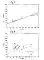
- Liene Halite An analysis of the E-S plot ( Figure 6) for the Liene Halite formation suggests that the data separate into five clusters denoted H1 to H5. Table 1 lists the symbols used to mark the clusters in Figure 6, and the depth range associated to each cluster. The discrimination of the Liene Halite into 5 sequences H1-H5 and their associated depth interval based on the E-S plot is supported by the geologist report and the gamma-ray log (plotted in Figure 7). The bed designated as H1 corresponds to gamma-ray values that are moderately high and somewhat erratic. The likely candidate for the lithology of H1 was identified as a mixed salt, possibly Carnalite.
- the bed H2 corresponds to another salt lithology; it is characterised by very uniform gamma-ray values in the range 60-70.
- the lithology for H3 is probably a red claystone which was First seen in the cuttings at 9,190' (2,801 m).
- the gamma-ray for this depth interval shows a transition from the high values of H2 to low values (about 10) characteristic of beds H4 and H5.
- cutting analysis and gamma-ray values unmistakedly identify H5 as an halite bed.
- the estimated friction angle for H5 poses a problem however, as the halite is characterised by a friction angle which is virtually zero at the pressure and temperature conditions encountered at those depths.
- a 'friction line' for a material like halite should be parallel to the S-axis.
- Applicant assumed that the drilling data for the halite bed are actually located on the cutting locus, ie on a line of slope ⁇ -1 going through the origin of the E-S diagram. Indeed the very low value of the intercept (Eo - -4 MPa) and the high value of the slope ( ⁇ ⁇ ⁇ 1.56) suggests that this hypothesis is plausible; in which case, ? - 0.64. In this scenario, variation of the drilling response would be caused by variation in the cohesion of the halite.
- the lithology of the sequence underlying the Liene Halite consists of a fairly pure anhydrite.
- all the data pertaining to the depth interval 9,305'-9,353' (2,836 - 2,850 m) appear to define a coherent cluster.
- This identification of a uniform lithology sequence correlates very well with the gamma-ray log (not shown), which indicates an approximately uniform low gamma-ray count value (below 10) in this depth interval.
- the segment of hole considered here was drilled with a 121 4" (31.11 cm) diameter bit.
- This bit has the usual characteristics of having the cutters mounted with a 30° backrake angle. Compared to a bit characterised by a 15° backrake angle, this large value of the rake angle is responsible for an increase of the intrinsic specific energy.
- the length of hole drilled during this bit run has a length of about 400' (122 m) between the depth 10,300' (3,139 m) and the depth 10,709' (3,264 m).
- the first 335' (102 m) of the segment was drilled through a limestone formation, and the last 75' (23 m) through a shale.
- the drilling data were logged at a frequency of one set of data per foot.
- Figure 9 shows the corresponding E-S plot; the data points for the limestone interval are represented by a circle (o), those for the shale formation by a plus sign (+).
- the two sets of points indeed differentiate into two clusters.
- the low value of the slope of the friction line suggests that the bit constant ⁇ is here equal to about 1.
- the friction angle is estimated to be about 45° for the limestone, and 23° for the shale.
- the intrinsic specific energy is not calculated here because these surface measurements are not accurate enough to warrant such a calculation.
Landscapes
- Engineering & Computer Science (AREA)
- Geology (AREA)
- Life Sciences & Earth Sciences (AREA)
- Mining & Mineral Resources (AREA)
- Environmental & Geological Engineering (AREA)
- Fluid Mechanics (AREA)
- Physics & Mathematics (AREA)
- General Life Sciences & Earth Sciences (AREA)
- Geochemistry & Mineralogy (AREA)
- Mechanical Engineering (AREA)
- Chemical & Material Sciences (AREA)
- Analytical Chemistry (AREA)
- Earth Drilling (AREA)
- Drilling And Boring (AREA)
Applications Claiming Priority (2)
| Application Number | Priority Date | Filing Date | Title |
|---|---|---|---|
| GB909015433A GB9015433D0 (en) | 1990-07-13 | 1990-07-13 | Method of determining the drilling conditions associated with the drilling of a formation with a drag bit |
| GB9015433 | 1990-07-13 |
Publications (3)
| Publication Number | Publication Date |
|---|---|
| EP0466255A2 true EP0466255A2 (de) | 1992-01-15 |
| EP0466255A3 EP0466255A3 (en) | 1993-02-10 |
| EP0466255B1 EP0466255B1 (de) | 1997-01-29 |
Family
ID=10679044
Family Applications (1)
| Application Number | Title | Priority Date | Filing Date |
|---|---|---|---|
| EP91201708A Expired - Lifetime EP0466255B1 (de) | 1990-07-13 | 1991-07-03 | Verfahren zum Bestimmen der Bohrbedingungen in Verbindung mit dem Bohren einer Formation mittels eines Fräsbohrmeissels |
Country Status (6)
| Country | Link |
|---|---|
| US (1) | US5216917A (de) |
| EP (1) | EP0466255B1 (de) |
| CA (1) | CA2047006C (de) |
| DE (1) | DE69124432D1 (de) |
| GB (1) | GB9015433D0 (de) |
| NO (1) | NO303745B1 (de) |
Cited By (15)
| Publication number | Priority date | Publication date | Assignee | Title |
|---|---|---|---|---|
| EP0551134A1 (de) * | 1992-01-09 | 1993-07-14 | Baker Hughes Incorporated | Verfahren zur Berechnung von Formations- und Bohrmeisselzuständen |
| US5323648A (en) * | 1992-03-06 | 1994-06-28 | Schlumberger Technology Corporation | Formation evaluation tool |
| GB2265923B (en) * | 1992-04-08 | 1996-06-05 | Baroid Technology Inc | System and method for controlling drill bit usage |
| EP0743423A1 (de) * | 1995-05-15 | 1996-11-20 | Institut Français du Pétrole | Verfahren zum Bestimmen der Bohrbedingungen unter Anwendung eines Modells |
| US5767399A (en) * | 1996-03-25 | 1998-06-16 | Dresser Industries, Inc. | Method of assaying compressive strength of rock |
| US5794720A (en) * | 1996-03-25 | 1998-08-18 | Dresser Industries, Inc. | Method of assaying downhole occurrences and conditions |
| US6109368A (en) * | 1996-03-25 | 2000-08-29 | Dresser Industries, Inc. | Method and system for predicting performance of a drilling system for a given formation |
| EP1070191A1 (de) * | 1998-04-02 | 2001-01-24 | Noble Engineering and Development Ltd. | Verfahren und vorrichtung zur optimierung des bohrfortschnitts |
| US6408953B1 (en) * | 1996-03-25 | 2002-06-25 | Halliburton Energy Services, Inc. | Method and system for predicting performance of a drilling system for a given formation |
| EP1443176A1 (de) * | 2003-02-01 | 2004-08-04 | HILTI Aktiengesellschaft | Vorschubgeregelte Kernbohrmaschine |
| US7032689B2 (en) * | 1996-03-25 | 2006-04-25 | Halliburton Energy Services, Inc. | Method and system for predicting performance of a drilling system of a given formation |
| US7085696B2 (en) | 1996-03-25 | 2006-08-01 | Halliburton Energy Services, Inc. | Iterative drilling simulation process for enhanced economic decision making |
| WO2012033622A1 (en) * | 2010-09-07 | 2012-03-15 | Saudi Arabian Oil Company | Determination of rock mechanics while slabbing |
| US8145462B2 (en) | 2004-04-19 | 2012-03-27 | Halliburton Energy Services, Inc. | Field synthesis system and method for optimizing drilling operations |
| EP3059385A1 (de) * | 2015-02-23 | 2016-08-24 | Geoservices Equipements | Systeme und Verfahren zur Bestimmung und/oder Anwendung der Schätzung einer Bohreffizienz |
Families Citing this family (73)
| Publication number | Priority date | Publication date | Assignee | Title |
|---|---|---|---|---|
| US5330016A (en) * | 1993-05-07 | 1994-07-19 | Barold Technology, Inc. | Drill bit and other downhole tools having electro-negative surfaces and sacrificial anodes to reduce mud balling |
| US5679894A (en) * | 1993-05-12 | 1997-10-21 | Baker Hughes Incorporated | Apparatus and method for drilling boreholes |
| US5358059A (en) * | 1993-09-27 | 1994-10-25 | Ho Hwa Shan | Apparatus and method for the dynamic measurement of a drill string employed in drilling |
| US5368108A (en) * | 1993-10-26 | 1994-11-29 | Schlumberger Technology Corporation | Optimized drilling with positive displacement drilling motors |
| US5670711A (en) * | 1996-03-08 | 1997-09-23 | Regents Of The University Of Minnesota | Portable rock strength evaluation device |
| US6019180A (en) * | 1997-05-05 | 2000-02-01 | Schlumberger Technology Corporation | Method for evaluating the power output of a drilling motor under downhole conditions |
| GB2340149B (en) * | 1998-08-04 | 2002-11-20 | Camco Internat | A method of determining characteristics of a rotary drag-type drill bit |
| US20040236553A1 (en) * | 1998-08-31 | 2004-11-25 | Shilin Chen | Three-dimensional tooth orientation for roller cone bits |
| US20040230413A1 (en) * | 1998-08-31 | 2004-11-18 | Shilin Chen | Roller cone bit design using multi-objective optimization |
| US7334652B2 (en) * | 1998-08-31 | 2008-02-26 | Halliburton Energy Services, Inc. | Roller cone drill bits with enhanced cutting elements and cutting structures |
| US20040045742A1 (en) * | 2001-04-10 | 2004-03-11 | Halliburton Energy Services, Inc. | Force-balanced roller-cone bits, systems, drilling methods, and design methods |
| US20030051917A1 (en) * | 1998-08-31 | 2003-03-20 | Halliburton Energy Services, Inc. | Roller cone bits, methods, and systems with anti-tracking variation in tooth orientation |
| US20040140130A1 (en) * | 1998-08-31 | 2004-07-22 | Halliburton Energy Services, Inc., A Delaware Corporation | Roller-cone bits, systems, drilling methods, and design methods with optimization of tooth orientation |
| ID28517A (id) * | 1998-08-31 | 2001-05-31 | Halliburton Energy Serv Inc | Bit kerucut penggulung daya seimbang, sistem metode pengeboran, dan metode disain |
| US8437995B2 (en) * | 1998-08-31 | 2013-05-07 | Halliburton Energy Services, Inc. | Drill bit and design method for optimizing distribution of individual cutter forces, torque, work, or power |
| US6353799B1 (en) | 1999-02-24 | 2002-03-05 | Baker Hughes Incorporated | Method and apparatus for determining potential interfacial severity for a formation |
| US6386297B1 (en) | 1999-02-24 | 2002-05-14 | Baker Hughes Incorporated | Method and apparatus for determining potential abrasivity in a wellbore |
| US6276465B1 (en) | 1999-02-24 | 2001-08-21 | Baker Hughes Incorporated | Method and apparatus for determining potential for drill bit performance |
| US9482055B2 (en) | 2000-10-11 | 2016-11-01 | Smith International, Inc. | Methods for modeling, designing, and optimizing the performance of drilling tool assemblies |
| US7251590B2 (en) * | 2000-03-13 | 2007-07-31 | Smith International, Inc. | Dynamic vibrational control |
| US8589124B2 (en) * | 2000-08-09 | 2013-11-19 | Smith International, Inc. | Methods for modeling wear of fixed cutter bits and for designing and optimizing fixed cutter bits |
| US6631772B2 (en) | 2000-08-21 | 2003-10-14 | Halliburton Energy Services, Inc. | Roller bit rearing wear detection system and method |
| US6634441B2 (en) | 2000-08-21 | 2003-10-21 | Halliburton Energy Services, Inc. | System and method for detecting roller bit bearing wear through cessation of roller element rotation |
| US7357197B2 (en) | 2000-11-07 | 2008-04-15 | Halliburton Energy Services, Inc. | Method and apparatus for monitoring the condition of a downhole drill bit, and communicating the condition to the surface |
| US6712160B1 (en) | 2000-11-07 | 2004-03-30 | Halliburton Energy Services Inc. | Leadless sub assembly for downhole detection system |
| US6722450B2 (en) | 2000-11-07 | 2004-04-20 | Halliburton Energy Svcs. Inc. | Adaptive filter prediction method and system for detecting drill bit failure and signaling surface operator |
| US6648082B2 (en) | 2000-11-07 | 2003-11-18 | Halliburton Energy Services, Inc. | Differential sensor measurement method and apparatus to detect a drill bit failure and signal surface operator |
| US6817425B2 (en) | 2000-11-07 | 2004-11-16 | Halliburton Energy Serv Inc | Mean strain ratio analysis method and system for detecting drill bit failure and signaling surface operator |
| US9051781B2 (en) | 2009-08-13 | 2015-06-09 | Smart Drilling And Completion, Inc. | Mud motor assembly |
| US9745799B2 (en) | 2001-08-19 | 2017-08-29 | Smart Drilling And Completion, Inc. | Mud motor assembly |
| DE10254942B3 (de) * | 2002-11-25 | 2004-08-12 | Siemens Ag | Verfahren zur automatischen Ermittlung der Koordinaten von Abbildern von Marken in einem Volumendatensatz und medizinische Vorrichtung |
| FR2855631A1 (fr) * | 2003-06-02 | 2004-12-03 | Inst Francais Du Petrole | Methode pour optimiser la production d'un gisement petrolier en presence d'incertitudes |
| GB2420203B (en) * | 2003-07-09 | 2007-02-21 | Smith International | Methods for modeling wear of fixed cutter bits and for designing and optimizing fixed cutter bits |
| US20040105741A1 (en) * | 2003-07-14 | 2004-06-03 | Pat Inglese | Wet (plastic) and dry concrete reclamation/disposal device |
| US7031840B1 (en) * | 2004-01-05 | 2006-04-18 | Oil & Gas Consultants International, In. | Drilling performance assessment process |
| US7434632B2 (en) * | 2004-03-02 | 2008-10-14 | Halliburton Energy Services, Inc. | Roller cone drill bits with enhanced drilling stability and extended life of associated bearings and seals |
| US7360612B2 (en) | 2004-08-16 | 2008-04-22 | Halliburton Energy Services, Inc. | Roller cone drill bits with optimized bearing structures |
| US7412331B2 (en) * | 2004-12-16 | 2008-08-12 | Chevron U.S.A. Inc. | Method for predicting rate of penetration using bit-specific coefficient of sliding friction and mechanical efficiency as a function of confined compressive strength |
| US7555414B2 (en) * | 2004-12-16 | 2009-06-30 | Chevron U.S.A. Inc. | Method for estimating confined compressive strength for rock formations utilizing skempton theory |
| US7243735B2 (en) * | 2005-01-26 | 2007-07-17 | Varco I/P, Inc. | Wellbore operations monitoring and control systems and methods |
| CA2624106C (en) | 2005-08-08 | 2013-07-09 | Halliburton Energy Services, Inc. | Methods and systems for designing and/or selecting drilling equipment with desired drill bit steerability |
| US7860693B2 (en) | 2005-08-08 | 2010-12-28 | Halliburton Energy Services, Inc. | Methods and systems for designing and/or selecting drilling equipment using predictions of rotary drill bit walk |
| US20090229888A1 (en) * | 2005-08-08 | 2009-09-17 | Shilin Chen | Methods and systems for designing and/or selecting drilling equipment using predictions of rotary drill bit walk |
| RU2008122703A (ru) * | 2005-11-08 | 2009-12-20 | Бейкер Хьюз Инкорпорейтед (Us) | Долото лопастного типа для роторного бурения и способы оптимизации их эффективности и износостойкости |
| US7836975B2 (en) * | 2007-10-24 | 2010-11-23 | Schlumberger Technology Corporation | Morphable bit |
| GB2468251B (en) | 2007-11-30 | 2012-08-15 | Halliburton Energy Serv Inc | Method and system for predicting performance of a drilling system having multiple cutting structures |
| WO2009079371A1 (en) * | 2007-12-14 | 2009-06-25 | Halliburton Energy Services, Inc. | Methods and systems to predict rotary drill bit walk and to design rotary drill bits and other downhole tools |
| US8234912B2 (en) * | 2008-04-16 | 2012-08-07 | Terratek Inc. | Apparatus for continuous measurement of heterogeneity of geomaterials |
| US20090260883A1 (en) * | 2008-04-16 | 2009-10-22 | Terratek Inc. | Continuous measurement of heterogeneity of geomaterials |
| BRPI0919556B8 (pt) | 2008-10-03 | 2019-07-30 | Halliburton Energy Services Inc | método, sistema para perfurar um poço, e, meio legível por computador |
| US8006781B2 (en) | 2008-12-04 | 2011-08-30 | Baker Hughes Incorporated | Method of monitoring wear of rock bit cutters |
| US20100139987A1 (en) * | 2008-12-10 | 2010-06-10 | Baker Hughes Incorporated | Real time dull grading |
| US9624729B2 (en) | 2008-12-10 | 2017-04-18 | Baker Hughes Incorporated | Real time bit monitoring |
| BR112013010347A2 (pt) * | 2010-11-10 | 2016-08-02 | Baker Hughes Inc | sistema de controle de perfuração e método |
| US8899350B2 (en) * | 2010-12-16 | 2014-12-02 | Caterpillar Inc. | Method and apparatus for detection of drill bit wear |
| US9285794B2 (en) | 2011-09-07 | 2016-03-15 | Exxonmobil Upstream Research Company | Drilling advisory systems and methods with decision trees for learning and application modes |
| US20140122034A1 (en) * | 2011-12-09 | 2014-05-01 | Jonathan M. Hanson | Drill bit body rubbing simulation |
| US8967249B2 (en) | 2012-04-13 | 2015-03-03 | Schlumberger Technology Corporation | Reservoir and completion quality assessment in unconventional (shale gas) wells without logs or core |
| US9482084B2 (en) | 2012-09-06 | 2016-11-01 | Exxonmobil Upstream Research Company | Drilling advisory systems and methods to filter data |
| AU2013327663B2 (en) | 2012-10-03 | 2016-03-10 | Shell Internationale Research Maatschappij B.V. | Optimizing performance of a drilling assembly |
| SA113340567B1 (ar) | 2012-10-26 | 2015-07-07 | بيكر هوغيس انكوربوريتد | نظام وطريقة لمعالجة بيانات بئر باستخدام تحليل بيانات توبولوجية. |
| US9383304B2 (en) * | 2013-03-08 | 2016-07-05 | Diamond Innovations, Inc. | Laboratory assessment of PDC cutter design under mixed-mode conditions |
| US20140250994A1 (en) * | 2013-03-08 | 2014-09-11 | Diamond Innovations, Inc. | Laboratory assessment of pdc cutter design under mixed-mode conditions |
| US10119337B2 (en) * | 2014-11-20 | 2018-11-06 | Halliburton Energy Services, Inc. | Modeling of interactions between formation and downhole drilling tool with wearflat |
| GB2546649A (en) | 2014-11-20 | 2017-07-26 | Halliburton Energy Services Inc | Earth formation crushing model |
| CA2964876C (en) * | 2014-11-26 | 2019-10-29 | Halliburton Energy Services, Inc. | Hybrid mechanical-laser drilling equipment |
| US20160305231A1 (en) * | 2015-04-14 | 2016-10-20 | Bp Corporation North America Inc. | System and Method for Drilling using Pore Pressure |
| US11796434B2 (en) | 2019-08-16 | 2023-10-24 | Schlumberger Technology Corporation | Apparatus and method for testing rock heterogeneity |
| US11321506B2 (en) * | 2019-09-17 | 2022-05-03 | Regents Of The University Of Minnesota | Fast algorithm to simulate the response of PDC bits |
| CN111209684B (zh) * | 2020-01-15 | 2024-03-22 | 西安理工大学 | 一种基于随钻监测技术的岩石强度参数的超前预报方法 |
| US11905828B1 (en) * | 2022-07-27 | 2024-02-20 | Halliburton Energy Services, Inc. | Monitoring drilling conditions and estimating rock properties |
| US12037886B1 (en) | 2023-01-19 | 2024-07-16 | Saudi Arabian Oil Company | Evaluating carbon dioxide emission during drilling operations |
| CN115952623B (zh) * | 2023-03-09 | 2023-05-30 | 北京城建集团有限责任公司 | 一种砂卵石地层盾构刀具均匀磨损的刀盘刀具设计方法 |
Citations (3)
| Publication number | Priority date | Publication date | Assignee | Title |
|---|---|---|---|---|
| EP0163426A1 (de) * | 1984-05-03 | 1985-12-04 | Anadrill International SA | Verfahren und Vorrichtung zur Überwachung von Bohrbedingungen |
| US4627276A (en) * | 1984-12-27 | 1986-12-09 | Schlumberger Technology Corporation | Method for measuring bit wear during drilling |
| EP0350978A1 (de) * | 1988-07-13 | 1990-01-17 | Anadrill International SA | Verfahren zur Bestimmung von Bohrbedingungen während des Bohrens |
Family Cites Families (3)
| Publication number | Priority date | Publication date | Assignee | Title |
|---|---|---|---|---|
| US4697650A (en) * | 1984-09-24 | 1987-10-06 | Nl Industries, Inc. | Method for estimating formation characteristics of the exposed bottomhole formation |
| GB2188354B (en) * | 1986-03-27 | 1989-11-22 | Shell Int Research | Rotary drill bit |
| US4876886A (en) * | 1988-04-04 | 1989-10-31 | Anadrill, Inc. | Method for detecting drilling events from measurement while drilling sensors |
-
1990
- 1990-07-13 GB GB909015433A patent/GB9015433D0/en active Pending
-
1991
- 1991-07-03 DE DE69124432T patent/DE69124432D1/de not_active Expired - Lifetime
- 1991-07-03 EP EP91201708A patent/EP0466255B1/de not_active Expired - Lifetime
- 1991-07-11 US US07/728,442 patent/US5216917A/en not_active Expired - Lifetime
- 1991-07-12 CA CA002047006A patent/CA2047006C/en not_active Expired - Fee Related
- 1991-07-12 NO NO912751A patent/NO303745B1/no unknown
Patent Citations (3)
| Publication number | Priority date | Publication date | Assignee | Title |
|---|---|---|---|---|
| EP0163426A1 (de) * | 1984-05-03 | 1985-12-04 | Anadrill International SA | Verfahren und Vorrichtung zur Überwachung von Bohrbedingungen |
| US4627276A (en) * | 1984-12-27 | 1986-12-09 | Schlumberger Technology Corporation | Method for measuring bit wear during drilling |
| EP0350978A1 (de) * | 1988-07-13 | 1990-01-17 | Anadrill International SA | Verfahren zur Bestimmung von Bohrbedingungen während des Bohrens |
Cited By (25)
| Publication number | Priority date | Publication date | Assignee | Title |
|---|---|---|---|---|
| EP0551134A1 (de) * | 1992-01-09 | 1993-07-14 | Baker Hughes Incorporated | Verfahren zur Berechnung von Formations- und Bohrmeisselzuständen |
| US5415030A (en) * | 1992-01-09 | 1995-05-16 | Baker Hughes Incorporated | Method for evaluating formations and bit conditions |
| US5323648A (en) * | 1992-03-06 | 1994-06-28 | Schlumberger Technology Corporation | Formation evaluation tool |
| GB2265923B (en) * | 1992-04-08 | 1996-06-05 | Baroid Technology Inc | System and method for controlling drill bit usage |
| EP0743423A1 (de) * | 1995-05-15 | 1996-11-20 | Institut Français du Pétrole | Verfahren zum Bestimmen der Bohrbedingungen unter Anwendung eines Modells |
| FR2734315A1 (fr) * | 1995-05-15 | 1996-11-22 | Inst Francais Du Petrole | Methode de determination des conditions de forage comportant un modele de foration |
| US5730234A (en) * | 1995-05-15 | 1998-03-24 | Institut Francais Du Petrole | Method for determining drilling conditions comprising a drilling model |
| US6408953B1 (en) * | 1996-03-25 | 2002-06-25 | Halliburton Energy Services, Inc. | Method and system for predicting performance of a drilling system for a given formation |
| US7035778B2 (en) | 1996-03-25 | 2006-04-25 | Halliburton Energy Services, Inc. | Method of assaying downhole occurrences and conditions |
| US6109368A (en) * | 1996-03-25 | 2000-08-29 | Dresser Industries, Inc. | Method and system for predicting performance of a drilling system for a given formation |
| US6131673A (en) * | 1996-03-25 | 2000-10-17 | Dresser Industries, Inc. | Method of assaying downhole occurrences and conditions |
| US7357196B2 (en) | 1996-03-25 | 2008-04-15 | Halliburton Energy Services, Inc. | Method and system for predicting performance of a drilling system for a given formation |
| US5767399A (en) * | 1996-03-25 | 1998-06-16 | Dresser Industries, Inc. | Method of assaying compressive strength of rock |
| US7261167B2 (en) | 1996-03-25 | 2007-08-28 | Halliburton Energy Services, Inc. | Method and system for predicting performance of a drilling system for a given formation |
| US7085696B2 (en) | 1996-03-25 | 2006-08-01 | Halliburton Energy Services, Inc. | Iterative drilling simulation process for enhanced economic decision making |
| US7032689B2 (en) * | 1996-03-25 | 2006-04-25 | Halliburton Energy Services, Inc. | Method and system for predicting performance of a drilling system of a given formation |
| US5794720A (en) * | 1996-03-25 | 1998-08-18 | Dresser Industries, Inc. | Method of assaying downhole occurrences and conditions |
| EP1070191A4 (de) * | 1998-04-02 | 2004-03-17 | Noble Engineering And Dev Ltd | Verfahren und vorrichtung zur optimierung des bohrfortschnitts |
| EP1070191A1 (de) * | 1998-04-02 | 2001-01-24 | Noble Engineering and Development Ltd. | Verfahren und vorrichtung zur optimierung des bohrfortschnitts |
| EP1443176A1 (de) * | 2003-02-01 | 2004-08-04 | HILTI Aktiengesellschaft | Vorschubgeregelte Kernbohrmaschine |
| US8145462B2 (en) | 2004-04-19 | 2012-03-27 | Halliburton Energy Services, Inc. | Field synthesis system and method for optimizing drilling operations |
| WO2012033622A1 (en) * | 2010-09-07 | 2012-03-15 | Saudi Arabian Oil Company | Determination of rock mechanics while slabbing |
| EP3059385A1 (de) * | 2015-02-23 | 2016-08-24 | Geoservices Equipements | Systeme und Verfahren zur Bestimmung und/oder Anwendung der Schätzung einer Bohreffizienz |
| WO2016135145A1 (en) * | 2015-02-23 | 2016-09-01 | Geoservices Equipements | Systems and methods for determining and/or using estimate of drilling efficiency |
| US11230914B2 (en) | 2015-02-23 | 2022-01-25 | Schlumberger Technology Corporation | Systems and methods for determining and/or using estimate of drilling efficiency |
Also Published As
| Publication number | Publication date |
|---|---|
| EP0466255A3 (en) | 1993-02-10 |
| CA2047006C (en) | 2004-02-10 |
| EP0466255B1 (de) | 1997-01-29 |
| US5216917A (en) | 1993-06-08 |
| DE69124432D1 (de) | 1997-03-13 |
| NO912751L (no) | 1992-01-14 |
| CA2047006A1 (en) | 1992-01-14 |
| NO912751D0 (no) | 1991-07-12 |
| GB9015433D0 (en) | 1990-08-29 |
| NO303745B1 (no) | 1998-08-24 |
Similar Documents
| Publication | Publication Date | Title |
|---|---|---|
| US5216917A (en) | Method of determining the drilling conditions associated with the drilling of a formation with a drag bit | |
| CA2322118C (en) | Method for optimizing drill bit and drilling parameter selection using rock strength measurements made from drill cuttings | |
| EP0350978B1 (de) | Verfahren zur Bestimmung von Bohrbedingungen während des Bohrens | |
| US7991554B2 (en) | Method for predicting rate of penetration using bit-specific coefficients of sliding friction and mechanical efficiency as a function of confined compressive strength | |
| CA2653115C (en) | Method to determine rock properties from drilling logs | |
| EP0551134A1 (de) | Verfahren zur Berechnung von Formations- und Bohrmeisselzuständen | |
| Warren | Drilling model for soft-formation bits | |
| US9915130B2 (en) | Method for assessing the performance of a drill bit configuration, and for comparing the performance of different drill bit configurations for drilling similar rock formations | |
| Kerkar et al. | Estimation of rock compressive strength using downhole weight-on-bit and drilling models | |
| CA2935247A1 (en) | Model for estimating drilling tool wear | |
| WO2001025597A1 (en) | Method for selecting drilling parameters | |
| Uboldi et al. | Rock strength measurements on cuttings as input data for optimizing drill bit selection | |
| EP0351902B1 (de) | Verfahren zur Bestimmung der Porosität einer unterirdischen Formation während des Bohrens | |
| Celada et al. | The use of the specific drilling energy for rock mass characterisation and TBM driving during tunnel construction | |
| Farrelly et al. | Bit performance and selection: a novel approach | |
| Peck | Performance monitoring of rotary blasthole drills | |
| Rasmus et al. | Real-time pore-pressure evaluation from MWD/LWD measurements and drilling-derived formation strength | |
| Prasad et al. | An Innovative and Independent Method for Formation Strengths and Facies Identification Using Real-Time Downhole Drilling Data, and its Application in Geosteering for Optimal Well Placement | |
| Prasad et al. | An Innovative and Reliable Method of Estimating Rock Strength From Drilling Data Acquired Downhole | |
| Cui et al. | Maximizing drilling performance with real-time drilling vibration mitigation in the deep wells | |
| Maguire et al. | Look-ahead-while-drilling resistivity tools and their role in drilling sedimentary basins containing complex volcanic geology | |
| Sæther | Detection of Bit Wear in Sandstone and Conglomerate-Analysis of Drilling Data and Formation Characteristics | |
| Achmatukaev | Field Case Study of Drill Bit Performance Analysis in Valhall Flank West | |
| Hmayed | Ormen Lange 6305/7 drilling data based ROP modelling and its application | |
| Kenupp et al. | DURING LOSS OF BIT STABILIZATION EVENTS |
Legal Events
| Date | Code | Title | Description |
|---|---|---|---|
| PUAI | Public reference made under article 153(3) epc to a published international application that has entered the european phase |
Free format text: ORIGINAL CODE: 0009012 |
|
| AK | Designated contracting states |
Kind code of ref document: A2 Designated state(s): DE DK FR GB IT NL |
|
| PUAL | Search report despatched |
Free format text: ORIGINAL CODE: 0009013 |
|
| AK | Designated contracting states |
Kind code of ref document: A3 Designated state(s): DE DK FR GB IT NL |
|
| 17P | Request for examination filed |
Effective date: 19930709 |
|
| 17Q | First examination report despatched |
Effective date: 19931202 |
|
| GRAG | Despatch of communication of intention to grant |
Free format text: ORIGINAL CODE: EPIDOS AGRA |
|
| GRAH | Despatch of communication of intention to grant a patent |
Free format text: ORIGINAL CODE: EPIDOS IGRA |
|
| GRAH | Despatch of communication of intention to grant a patent |
Free format text: ORIGINAL CODE: EPIDOS IGRA |
|
| GRAA | (expected) grant |
Free format text: ORIGINAL CODE: 0009210 |
|
| AK | Designated contracting states |
Kind code of ref document: B1 Designated state(s): DE DK FR GB IT NL |
|
| PG25 | Lapsed in a contracting state [announced via postgrant information from national office to epo] |
Ref country code: IT Free format text: LAPSE BECAUSE OF FAILURE TO SUBMIT A TRANSLATION OF THE DESCRIPTION OR TO PAY THE FEE WITHIN THE PRESCRIBED TIME-LIMIT;WARNING: LAPSES OF ITALIAN PATENTS WITH EFFECTIVE DATE BEFORE 2007 MAY HAVE OCCURRED AT ANY TIME BEFORE 2007. THE CORRECT EFFECTIVE DATE MAY BE DIFFERENT FROM THE ONE RECORDED. Effective date: 19970129 Ref country code: DK Effective date: 19970129 Ref country code: FR Effective date: 19970129 Ref country code: NL Free format text: LAPSE BECAUSE OF FAILURE TO SUBMIT A TRANSLATION OF THE DESCRIPTION OR TO PAY THE FEE WITHIN THE PRESCRIBED TIME-LIMIT Effective date: 19970129 |
|
| REF | Corresponds to: |
Ref document number: 69124432 Country of ref document: DE Date of ref document: 19970313 |
|
| PG25 | Lapsed in a contracting state [announced via postgrant information from national office to epo] |
Ref country code: DE Effective date: 19970430 |
|
| EN | Fr: translation not filed | ||
| NLV1 | Nl: lapsed or annulled due to failure to fulfill the requirements of art. 29p and 29m of the patents act | ||
| PLBE | No opposition filed within time limit |
Free format text: ORIGINAL CODE: 0009261 |
|
| STAA | Information on the status of an ep patent application or granted ep patent |
Free format text: STATUS: NO OPPOSITION FILED WITHIN TIME LIMIT |
|
| 26N | No opposition filed | ||
| REG | Reference to a national code |
Ref country code: GB Ref legal event code: IF02 |
|
| PGFP | Annual fee paid to national office [announced via postgrant information from national office to epo] |
Ref country code: GB Payment date: 20070627 Year of fee payment: 17 |
|
| GBPC | Gb: european patent ceased through non-payment of renewal fee |
Effective date: 20080703 |
|
| PG25 | Lapsed in a contracting state [announced via postgrant information from national office to epo] |
Ref country code: GB Free format text: LAPSE BECAUSE OF NON-PAYMENT OF DUE FEES Effective date: 20080703 |