EP0466154A2 - Method and apparatus for representing motion of multiple-jointed object, computer graphic apparatus, and robot controller - Google Patents
Method and apparatus for representing motion of multiple-jointed object, computer graphic apparatus, and robot controller Download PDFInfo
- Publication number
- EP0466154A2 EP0466154A2 EP91111561A EP91111561A EP0466154A2 EP 0466154 A2 EP0466154 A2 EP 0466154A2 EP 91111561 A EP91111561 A EP 91111561A EP 91111561 A EP91111561 A EP 91111561A EP 0466154 A2 EP0466154 A2 EP 0466154A2
- Authority
- EP
- European Patent Office
- Prior art keywords
- motion
- function
- functions
- time
- joint
- Prior art date
- Legal status (The legal status is an assumption and is not a legal conclusion. Google has not performed a legal analysis and makes no representation as to the accuracy of the status listed.)
- Granted
Links
Images


Classifications
-
- B—PERFORMING OPERATIONS; TRANSPORTING
- B25—HAND TOOLS; PORTABLE POWER-DRIVEN TOOLS; MANIPULATORS
- B25J—MANIPULATORS; CHAMBERS PROVIDED WITH MANIPULATION DEVICES
- B25J9/00—Programme-controlled manipulators
- B25J9/16—Programme controls
-
- G—PHYSICS
- G06—COMPUTING; CALCULATING OR COUNTING
- G06T—IMAGE DATA PROCESSING OR GENERATION, IN GENERAL
- G06T13/00—Animation
- G06T13/20—3D [Three Dimensional] animation
- G06T13/40—3D [Three Dimensional] animation of characters, e.g. humans, animals or virtual beings
-
- G—PHYSICS
- G01—MEASURING; TESTING
- G01S—RADIO DIRECTION-FINDING; RADIO NAVIGATION; DETERMINING DISTANCE OR VELOCITY BY USE OF RADIO WAVES; LOCATING OR PRESENCE-DETECTING BY USE OF THE REFLECTION OR RERADIATION OF RADIO WAVES; ANALOGOUS ARRANGEMENTS USING OTHER WAVES
- G01S13/00—Systems using the reflection or reradiation of radio waves, e.g. radar systems; Analogous systems using reflection or reradiation of waves whose nature or wavelength is irrelevant or unspecified
- G01S13/02—Systems using reflection of radio waves, e.g. primary radar systems; Analogous systems
- G01S13/06—Systems determining position data of a target
- G01S13/08—Systems for measuring distance only
- G01S13/10—Systems for measuring distance only using transmission of interrupted, pulse modulated waves
- G01S13/26—Systems for measuring distance only using transmission of interrupted, pulse modulated waves wherein the transmitted pulses use a frequency- or phase-modulated carrier wave
- G01S13/28—Systems for measuring distance only using transmission of interrupted, pulse modulated waves wherein the transmitted pulses use a frequency- or phase-modulated carrier wave with time compression of received pulses
- G01S13/284—Systems for measuring distance only using transmission of interrupted, pulse modulated waves wherein the transmitted pulses use a frequency- or phase-modulated carrier wave with time compression of received pulses using coded pulses
- G01S13/288—Systems for measuring distance only using transmission of interrupted, pulse modulated waves wherein the transmitted pulses use a frequency- or phase-modulated carrier wave with time compression of received pulses using coded pulses phase modulated
-
- G—PHYSICS
- G01—MEASURING; TESTING
- G01S—RADIO DIRECTION-FINDING; RADIO NAVIGATION; DETERMINING DISTANCE OR VELOCITY BY USE OF RADIO WAVES; LOCATING OR PRESENCE-DETECTING BY USE OF THE REFLECTION OR RERADIATION OF RADIO WAVES; ANALOGOUS ARRANGEMENTS USING OTHER WAVES
- G01S7/00—Details of systems according to groups G01S13/00, G01S15/00, G01S17/00
- G01S7/02—Details of systems according to groups G01S13/00, G01S15/00, G01S17/00 of systems according to group G01S13/00
- G01S7/28—Details of pulse systems
- G01S7/285—Receivers
- G01S7/288—Coherent receivers
Abstract
Description
- The present invention relates to a method of representing a motion in which a motion of a multiple-articulated object such as a human or an animal is represented, and in particular, to a motion representation method, a motion representing apparatus, a computer graphic apparatus, and a robot controller suitable for facilitating an operation to set and to change a motion of the multiple-hinged object when a size thereof is altered and for enabling various kinds of motions to be represented.
- In order to represent in computer graphics such motions as walking and running actions of a human and motions of a horse and a spanworm, a key frame method has been employed in general. According to the key frame method, to generate motions of a multiple-articulated object such as a human or a horse, the user first defines contours thereof at a point of time and at a subsequent point of time, respectively. Contours between these periods are determined based on an interpolation so that the respective contours or shapes thus attained are sequentially displayed in a time-series manner to resultantly produce a motion picture in which the multiple-jointed object seems to make a real action. However, the key frame method is attended with a problem that the contours thus determined in the time-series manner for the motion of the object takes a long period of time, which hence requires a considerably large amount of processing time and which imposes a heavy load on the operator.
- Heretofore, to overcome this problem, as described in an article entitled "A Study of Computer Animation Composed of Animation Primitives by Trigonometric Motion Approximation" written in the Proceedings of IECE of Japan, Jan. 1980, Vol. J63-D No. 1, an action of a human is shot by a camera to attain an animation picture thereof on a 16 millimeter (mm) film so as to measure movements of representative points of joints or articulations. For each joint portion above, horizontal and vertical positions X and Y thereof are obtained in centimeters relative to reference positions in a form of a function of time T, thereby determining a locus of the movement of each joint portion. Thereafter, the locus of the movement is approximated by a straight line and a trigonometric curve such that the computer system achieves computations on the approxiamted curve to attain respective contour data items in a time sequence, which are then sequentially displayed as a motion picture in the graphic system.
- According to the prior art above, the movement of each articulation thus obtained through the shooting operation on a 16 mm film is analyzed to extract changes in the X-directional and Y-directional positions relative to the respective reference positions at each point of time, thereby determining the approximated curve of the motion of the human. Consequently, a satisfactory animation picture is developed when the action is to be expressed by the approximated curve. However, the approxiamted curve cannot be applied to a case, for example, where the size of the object is varied or where dimensional ratios between the respective joints are altered in the motion. In this case, there arises a problem that the shooting operation is required to be again actually achieved on the object with the pertinent size and/or with the associated ratio between the joints, which leads to a limited degree of freedom for representing the animation. That is, according to the conventional technology, when generating a motion picture of a multiple-jointed object in the computer graphic system, the image can be presented only as an analogy of the real object thus undergone the shooting operation. This means that various actions cannot be developed in computer graphics. For example, only an ordinary walking action of a human shot by the camera can be displayed in the graphic image. Namely, even when the ordinary or standard action is modified, a motion picture of, for example, a violent walking action or a joyful or pleasant walking motion cannot be obtained. In consequence, heretofore, to express such an action above, for example, a human model is required to actually walk with a violent feeling to be shot by a camera so as to attain an image of the violent walk, which is then analyzed to implement an objective animation picture. In other words, for example, when producing a motion picture of animals, insects, and imaginary objects of which various actions cannot be actually shot by a camera, various movements thereof cannot be easily presented in computer graphics.
- In addition, it has been impossible in the conventional technology to produce an action with a human sentimental feature, which is usually expressed, for example, by a feature. That is, a characteristic action with a human emotion cannot be reflected on animation picture of the multiple-jointed object.
- It is therefore an object of the present invention to provide a motion representation method and a computer graphic apparatus in which even when a size of a multiple-jointed object and/or a dimensional ratio between joints thereof are altered, a motion of the object can be easily changed in computer graphics.
- Another object of the present invention is to provide a motion representation method and a computer graphic apparatus in which a multiple-articulated object can achieve various motions such as those having characteristics of actions of the object in computer graphics.
- Still another object of the present invention is to provide a method of and an apparatus for controlling a robot in which an action of the robot can be determined independent of a size thereof and in which instructions of various motions can be issued to the robot, thereby solving a problem, similar to that described above, appearing when the robot is actually operated for various actions.
- A first feature of the present invention resides in that in a case where a motion of a multiple-articulated object is presented on a display screen by controlling an action of each joint of the object, a bending angle of each articulation is expressed by a function independent of a length between articulations such that data of a contour of the multiple-jointed object in motion are obtained from the function, thereby displaying an image of the object according to a change in a size and/or a dimensional ratio between joints thereof.
- A second feature of the present invention resides suitably in that in a case where a motion of a multiple-jointed object is presented on a display screen by controlling an action of each joint of the object, a bending angle of each articulation is expressed by the following function independent of a length between articulations.

- Dm:
- Direct-current component
- Amn:
- Amplitude of each frequency component
- ψmn:
- Phase
- m:
- Joint number
- n:
- Higher harmonic of n-th order
- Φm:
- Phase difference of 1st order higher harmonics between reference joint and m-th joint (Φm = 0 for reference joint)
- Data of a contour of the multiple-jointed object in motion are obtained from values of the function ϑm(t) for each joint.
- A third feature of the present invention resides in that when a motion of a multiple-jointed object is presented on a display screen by controlling an action of each joint of the object, a bending angle of each articulation is expressed by a function independent of a length between articulations and components of the respective functions are modified when presenting the motion of the object.
- A fourth feature of the present invention resides in that in the function (1), at least either one of the parameter values of Dm, Amn, and ψmn is changed.
- A fifth feature of the present invention resides in that in a robot control operation in which instructions of operations are supplied to a multiple-jointed robot so as to instruct the robot to achieve a desired motion, a bending angle of each articulation is expressed by a function independent of a length between articulations such that positional data is computed for each joint of the robot based on the function, thereby producing the operational instructions.
- A sixth feature of the present invention resides in that a bending angle of each joint of a multiple-jointed object is expressed by a function independent of a length between joints so as to reflect onto the function a feature of a motion such as one expressed by an element of a human emotion which may be linguistically represented by a feature.
- A seventh feature of the present invention resides in that when presenting a motion of a multiple-jointed object on a display screen by controlling an action of each joint of the object, the action of the object is expressed by a function of time. Means for changing parameters disposed to develop various kinds of motions includes at least either one of means for obtaining a mean value of parameters of each function of time representing a plurality of actions, means for controlling a direction or an orientation of the multiple-jointed object, means for creating a route of a motion, means for changing a stride length between an inner side and an outer side of a curve, means for taking into consideration an influence of a centrifugal force, means for controlling a stride length in the motion, means for interpolating the function of time with respect to space, means for combining an action created in the key frame method with an action generated from the function of time, means for producing a function of time from measured data, means for generating a function of time from the action created in the key frame method, and means for correcting the function of time.
- As above, when a bending angle of each articulation of a multiple-hinged object is expressed by a function, the angle can be independent of a length between articualtions. Consequently, in a case when a contour of the multiple-jointed object to be displayed is computed depending on the bending angle of each joint, the computation can be accomplished independently of the size of the object, namely, the function need not be prepared again for the computation. In consequence, even when the multi-articulated object is changed in its size, the computation of the contour thereof can be carried out by use of the functions beforehand prepared. Moreover, to change the representation of the motion, the user need only modify parameters of the functions to alter, for example, a change rate of the bending angle of each joint.
- Furthermore, when computing mean values of the respective parameters of the functions of time representing a plurality of actions in the motion representation, the motion can be represented depending on a mean value of a plurality of functions of time.
- The user may control the proceeding direction of the motion by adjusting the direction of the multiple-articulated object.
- The object can be arbitrarily moved or displaced in a space based on a route of the motion beforehand prepared.
- The inching width is varied between the inner and outer sides of a curve and hence the slip of a foot is prevented.
- Owing to the influence of the centrifugal force taken into consideration, an inclination of a body can be presented in a circular motion.
- The number of steps in an interval can be controlled depending on a stride width supervised in a movement.
- Based on an interpolation of a function of time with respect to a space, the motion can be altered while the object is being moved. Depending on an interpolation of a function of time with respect to time, the motion can be varied depending on an elapsed time.
- By combining a motion produced in the key frame method with one created from a function of time, there can be represented a motion which cannot be represented only from the function of time.
- Measured data are processed to generate a function of time, which enables an actual motion to be produced depending on the function of time.
- A function of time is created from a motion obtained in the key frame method and hence an imaginary action not actually existing in the accessible environment can be produced from the function of time.
- A function of time can be corrected by interpolating the function of time.
-
- Fig. 1 is a schematic diagram showing the configuration of a computer graphic apparatus in a first embodiment according to the present invention;
- Fig. 2 is a diagram showing the display screen layout of the computer graphic apparatus;
- Fig. 3 is a diagram showing an image of a human in a line drawing;
- Fig. 4 is a graph presenting measured values of a change in the bending angles of primary joints of the human;
- Fig. 5 is a graph showing a spectrum related to a curve 3a of Fig. 4;
- Fig. 6 is a schematic diagram showing the configuration of a computer graphic apparatus in a second embodiment according to the present invention;
- Fig. 7A is a graph, identical to the curve 3a of Fig. 4, presenting the bending angle change of a knee articulation in an ordinary walking action;
- Fig. 7B is a graph showing the bending angle change of a knee articulation in a joyful walking action;
- Fig. 8 is a graph showing a spectrum related to the curve of Fig. 7B;
- Fig. 9 is a graph showing a difference between spectra of Figs. 5 and 8, respectively;
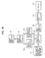
- Fig. 10 is a schematic diagram showing the configuration of a computer graphic apparatus in a third embodiment according to the present invention;
- Fig. 11 is a schematic diagram showing the configuration of a computer graphic apparatus in a fourth embodiment according to the present invention;
- Fig. 12 is a diagram showing the constitution of a control system of a multiple-jointed object in a fifth embodiment according to the present invention;
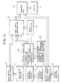
- Fig. 13 is a diagram showing the configuration of a control system of a multiple-jointed object in a sixth embodiment according to the present invention;
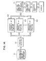
- Fig. 14 is a diagram showing the constitution of a control system of a multiple-jointed object in a seventh embodiment according to the present invention;
- Fig. 15 is a diagram showing the configuration of a control system of a multiple-jointed object in a eighth embodiment according to the present invention;
- Fig. 16 is a diagram illustratively showing a relationship between a transit point and a moving direction;
- Fig. 17 is a diagram showing the configuration of a control system of a multiple-jointed object in a ninth embodiment according to the present invention;
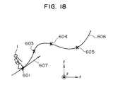
- Fig. 18 is a diagram showing relationships between transit points and a moving direction;
- Fig. 19 is a diagram showing the configuration of a control system of a multiple-jointed object in a tenth embodiment according to the present invention;
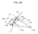
- Fig. 20 is a diagram showing relationship of strides in a movement along a curve;
- Fig. 21 is a diagram showing the configuration of a control system of a multiple-jointed object in an 11th embodiment according to the present invention;
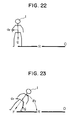
- Fig. 22 is a diagram schematically showing components of force applied onto a human in a circular motion;
- Fig. 23 is a diagram showing a correction of a human posture;
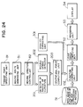
- Fig. 24 is a diagram showing the configuration of a control system of a multiple-jointed object in a 12th embodiment according to the present invention;
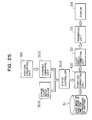
- Fig. 25 is a diagram showing the configuration of a control system of a multiple-jointed object in a 13th embodiment according to the present invention;
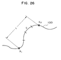
- Fig. 26 is a diagram showing a relationship between a moving route and a stride length;
- Fig. 27 is a diagram showing the constitution of a control system of a multiple-jointed object in a 14th embodiment according to the present invention;
- Fig. 28 is a diagram schematically showing relationships between periods of time and stride lengths;
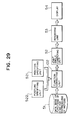
- Fig. 29 is a diagram showing the configuration of a control system of a multiple-jointed object in a 15th embodiment according to the present invention;
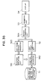
- Fig. 30 is a diagram showing the constitution of a control system of a multiple-jointed object in a 16th embodiment according to the present invention;
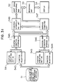
- Fig. 31 is a diagram showing the configuration of a control system of a multiple-jointed object in a 17th embodiment according to the present invention;
- Fig. 32 is a diagram illustratively showing an interpolation of an image during a displacement thereof;
- Fig. 33 is a diagram showing the configuration of a control system of a multiple-jointed object in an 18th embodiment according to the present invention;
- Fig. 34 is a diagram showing an interpolation of a motion with respect to time;
- Fig. 35 is a diagram showing the constitution of a control system of a multiple-jointed object in a 19th embodiment according to the present invention;
- Fig. 36 is a diagram showing the configuration of a control system of a multiple-jointed object in a 20th embodiment according to the present invention;
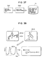
- Fig. 37 is a diagram showing the constitution of a system in which a function of time is created from measured data;
- Fig. 38 is a schematic diagram showing a method of generating a function of time representing a motion;
- Fig. 39 is a diagram showing another system in which a function of time is produced from measured data;
- Fig. 40 is a diagram showing still another system in which a function of time is generated from data measured in the key frame method;
- Fig. 41 is a diagram showing the configuration of a system for correcting a data base;
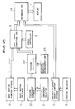
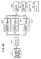
- Fig. 42 is a diagram showing the configuration of a control system of a multiple-jointed object in a 21st embodiment according to the present invention;
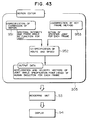
- Fig. 43 is a diagram showing the operation of an editing section of the embodiments above in which various parameters are supplied from a display screen;
- Fig. 44 is a diagram illustratively showing a screen example employed to specify expressions of a motion;
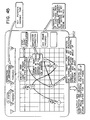
- Fig. 45 is a diagram showing an example of a screen used to specify a route and a speed of an action in the motion editor;
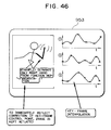
- Fig. 46 is a diagram showing a screen example adopted to correct a motion obtained by the key frame method in the motion editor;
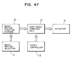
- Fig. 47 is a block diagram showing the configuration of a control system of a multiple-jointed object in a 22nd embodiment according to the present invention; and
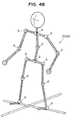
- Fig. 48 is a schematic perspective view showing the constitution of a robot.
- Referring now to the drawings, description will be given of embodiments according to the present invention.
- Fig. 1 shows the configuration of a computer graphic apparatus in a first embodiment according to the present invention. In this system, as shown in Fig. 2, an example of a multiple-jointed object i.e. a human is presented in an animation picture of a multiple-articulated
object 1 on a display screen such as a CRT. In operation of the computer graphic apparatus, the multiple-hingedobject 1 is represented as a multiple-jointed object in a linework as shown in Fig. 3. In this line drawing, a bending angle of each joint (acoxa 2, aknee joint 3, anelbow joint 4, and ashoulder joint 5 in the example of Fig. 3) is controlled to attain various kinds of contours. Thereafter, the body portion is added to the line drawing to display a motion image of a human (Fig. 2). - The computer graphic apapratus of Fig. 1 includes a basic
motion function storage 10 for storing therein for each basic motion a periodic function expressing a bending angle of each articulation, abasic motion selector 11 for selecting a desired function from the various functions loaded in thestorage 10, a jointangle computing unit 12 for receiving the function selected from thestorage 10 by theselector 11 and for computing based thereon a bending angle of the pertinent joint in a time series manner, aspeed controller 13 for controlling a speed at which thecomputing unit 12 achieves the computation of the joint angle in a time series fashion, namely, the speed of a motion conducted by the joint, a multiple-hingedobject contour storage 15 for storing therein contours used to draw bodies related to lineworks of the various multiple-jointed objects, acontour selector 16 for selecting a contour of a multiple-articulated object, arendering unit 14 for drawing a body for the motion of the multiple-jointed object, which is expressed only by joint bending angles computed by thecomputing unit 12, based on the contour read from thestorage 15, thereby generating image information for displaying the picture in a two-dimensional manner, and adisplay 17 for presenting the picture depending on the image information. - The basic
motion function storage 10 is loaded with functions associated with a motion of each joint for each basic action such as a walking action, a running action, or a sitting action. Under this condition, to select a basic motion, the operator picks a basicoperation specification icon 30 presented on the display screen as shown in Fig. 2. In the following paragraph, a walking action of a human image is taken as an example to be expressed by a function representing a motion to be displayed. - Fig. 4 is a graph showing curves representing changes with respect to time of measured bending angles of primary joints of a walking person viewed from a horizontal direction (X-axis direction).
Curves 2a, 3a, 4a, and 5a designate changes with respect to time of measured bending angles of the coxa, the knee joint, the elbow joint, and the shoulder joint, respectively. The angle changes are measured for two periods (strides or steps). These curves show correlations existing between the actions of the respective articulations. Fig. 5 is a spectral diagram obtained by achieving a Fourier analysis on the measure values 3a of the knee joint of Fig. 4. Essential spectrum compounds can be expressed by use of a function of atmost degree 
where, - Dm:
- Direct current component
- Amn:
- Amplitude of each frequency component
- ψmn:
- Phase
- m:
- Joint number
- n:
- Higher harmonic of n-th order
- Φn:
- Phase difference of 1st order higher harmonic between reference joint and m-th joint (Φm = 0 for reference joint)
- The joint
angle computing unit 12 of Fig. 1 achieves computations based on the function (1) to obtain an action of the knee joint while changing the value of the variable t such that the position of the joint is sequentially displayed at the point of time t, thereby presenting a motion picture of the knee. Incidentally, to set the action speed, the operator uses amotion specification icon 33 of Fig. 2. Namely, when the display item of avertical bar 40 in theicon 33 is horizontally shifted by a mouse cursor or the like, thespeed controller 13 of Fig. 1 is activated to develop its operation. The jointangle computing unit 12 computing based on the function (1) the values of Θm(t₁), Θm(t₂), Θm(t₃), etc. in a time series fashion increases the value of t₂ - t₁ = t₃ - t₂ = ... = Δt before achieving the computations when the operator specifies a higher motion speed. - Since the function (1) above does not include any parameter denoting a length, even when a size and/or a dimensional ratio between joints of the object are/is varied, the function (1) need not be modified. In consequence, also when it is desired to alter a size of a multi-hinged object to be displayed, the load imposed on the operator is not increased; moreover, after the size is changed, the animation picture of the multi-articulated object can be displayed at a high speed. That is, according to the embodiment above, the operator need only select a kind of each basic motion, a motion speed thereof, and a contour of each joint for a motion picture. Namely, a motion of a multi-jointed object can be developed with a quite small amount of information and through a small number of operation steps.
- Referring now to the motion representing apparatus of Fig. 1, the operation of the first embodiment will be described. First, the
contour storage 15 is loaded, for example, with contour data related to a state of a person image standing in an upright style and contour data of a basic posture of a flying butterfly. Thecontour selecting unit 16 selects desired contour data therefrom. For example, when the contour data of a person image are selected, the selected data are fed to therendering unit 14. On the other hand, the basicmotion function storage 10 is loaded, for example, with functions for which parameters of basic actions of a person such as a walking action, a running action, and a sitting action are respectively specified. One of the basic motions is selected by thebasic motion selector 11. For example, when a running action is selected, the function associated with the running action is transferred to the jointangle computing unit 12, which in turn achieves a computation of the function (1) to produce data of angles. The computation result is transferred together with a speed change rate indicated by thespeed controller 13 to therendering unit 14. Based on the contour data from thecontour storage 15 and the angle data thus received, therendering unit 14 creates image data to be sent to thedisplay 17, which resultantly presents thereon a picture of the image data. - Fig. 6 shows the constitution of a computer graphic apparatus in a second embodiment according to the present invention. As compared with the configuration of the first embodiment of Fig. 1, the second embodiment includes a
feature component storage 20 and afeature component selector 21. The jointangle computing unit 12 is configured to accomplish computations based on a selected basic operation function and a selected feature component. The feature component is here associated with a feature and is used to qualify an action or a motion. That is, the feature component is a feature such as joyfully, sadly, or delightfully. In this embodiment, the feature components are expressed in the form of functions so that the operator specifies a feature component to be selected. As can be seen from Fig. 2, the operator need only pick afeature selection icon 31 in the screen to choose a characteristic component. For example, with the mouse cursor or the like arranged over theicon 31, each time the left-side button is actuated features such as "joyfully", "merrily", "like a drunkard", and "calmly" are sequentially presented. When a desired feature is displayed on the screen, the operator actuates the right-side button to select the feature. In a case where "walk" is selected as the basic motion and "joyfully" is chosen as the feature element, the object of ahuman image 1 displayed achieves an indicated action, namely, theobject 1 walks joyfully or merrily. Next, a description will be given of a control operation of the characteristic element. - Fig. 7A is a graph presenting a change with respect to time of the measured bending angle of a knee joint in an ordinary walking action, whereas Fig. 7B is a graph showing a change with respect to time of the measured bending angle of a knee joint in a joyful walking action (i.e. the person walks joyfully). Fig. 8 shows a result of a spectral analysis achieved on the data of the joyful walking motion of Fig. 7B. In this connection, a result of a spectral analysis conducted on the measured values of the ordinary walking action of Fig. 7A is presented in the graph of Fig. 5. Consequently, a difference between the spectral analyses denotes the component associated with the feature "joyfully" as shown in Fig. 9. Teh graphs of Figs. 5, 8 and 9 present only the power spectrum components having respectively different phases. As can be seen from the spectral graph of Fig. 9, the primary spectrum representing the expression "joyfully" as a feature element can be expressed with a function of at
most degree 
where, - dm:
- Direct-current compound of "joyfully"
- amn:
- Component of "joyfully" in each frequency component
- ψmn:
- Phase compoennt of "joyfully"
- When the operator selects "joyfully" as the feature component by means of the selector 21 (Fig. 6), values of dm, am, and ψmn are read from the
feature component storage 20 to be substituted in the function (1), thereby attaining a function (2) to be fed to thecomputing unit 12. As a result, the system displays on the screen an animation picture of a joyfully walking person. - In accordance with the second embodiment, only the feature selection is added to the operations of the first embodiment so that the multiple-articulated object can conduct an action qualified by the selected feature.
- Since the operation of the motion representation apparatus of the second embodiment shown in Fig. 6 can be understood from the descriptions of the first embodiment of Fig. 1 and the second embodiment above, a redundant explanation thereof will be here omitted.
- Fig. 10 shows the configuration of a computer graphic apparatus in a third embodiment according to the present invention. When compared with the second embodiment of Fig. 6, this constitution additionally includes a
feature controller 22 and a featuremagnitude designating unit 23. In this embodiment, the jointangle computing unit 12 achieves computations based on the following function (3).
where, αm and βm denote a magnitude of a feature component and a magnitude or value of an amplitude, respectively. In this system, the feature magnitude αm is changed to specify motions with expressions in a range including, for example, "walk ordinarily", "walk joyfully", and "walk quite joyfully". Alternatively, as a feature "sadly" opposite to "joyfully", there may be specified motions with expressions such as "quite sadly", "ordinarily", and "quite joyfully". In this operation, when the display item of thevertical bar 40 is horizontally shifted in theicon 34 denoting the feature magnitude of Fig. 2, the featuremagnitude designating unit 23 specifies the desired magnitude of the feature component. The amplitude value βm is related to a stride length, which takes the larger value when the indication of thevertical bar 40 approches to the right end of theicon 32 of Fig. 2. Namely, the multiple-jointed object walks with a larger stride in the obtained animation picture. - According to the third embodiment, only by adding the magnitude specifying operation to the operations of the second embodiment, the degree of a feature component and a stride length can be altered; moreover, the feature magnitude and the stride length can be changed in a continuous manner.
- Fig. 11 shows the construction of a computer graphic apparatus in a fourth embodiment according to the present invention. As compared with the third embodiment in which only one kind of the feature of an action can be specified, the user can specify a plurality of features of an action in this embodiment. For this purpose, there are adopted a
feature controller 24 and a featuremagnitude designating unit 25. According to the fourth embodiment, a walking action may be accomplished with specifications of, for example, "joyfully" and "slowly". In this case, the computations are carried out with the following function (4). It is assumed in this function that the value of each parameter can be changed.
Since a plurality of characteristic components can be specified for an action, the objective action is conducted with a wider variety of emotional expressions. - As above, according to the fourth embodiment, the values of parameters of the function (4) can be altered in a successive manner; moreover, the expressions of the action conducted by an image of a person can be changed depending on the modified parameters in a realtime manner and through an interactive operation.
- In the description of the fourth embodiment, the apparatus controls the functions modified for a motion of a computer graphic image. However, when a computation result attained from the joint
angle computation unit 12 is employed as an operational instruction to control an operation of a multiple-articulated robot having a real size of the pertinent object, there can be implemented a robot controller operating independently of the size of the robot. Furthermore, since the actions to be sent as instructions to the robot can be qualified with the features, the robot can perform various kinds of actions with desired functions. - According to the
embodiments 1 to 4 described above, since the contour of a multiple-jointed object and/or a robot at an intermediate point of a motion can be computed by use of a function independent of the size thereof, multiple-hinged objects and/or robots of various sizes can be actuated in a realtime manner. In addition, the action can be qualified by a feature of the action; moreover, the degree of the feature can be varied. Consequently, the motion can be accomplished with quite a large number of functions. - Although a human model has been described in conjunction with the
embodiments 1 to 4 above, an effect similar to those of the embodiments can naturally be developed also for an object such as a measuring worm. - Referring next to Fig. 12, a description will be given of a computer graphic apparatus in a fifth embodiment according to the present invention. The constitution of Fig. 12 includes a
data base 51 for storing therein functions of time for expressions of motions, a jointangle computing unit 52, arendering unit 53, adisplay 54, and acontroller 55. Let us assume here that in order to actuate a person image, a bending angle of each joint is varied with respect to time based on the following function.
- This function expressing a joint bending angle with respect to time is obtained from a Fourier series expansion of a period function in which a letter m denotes a joint number. To represent a motion of the entire human body, there are required a function ϑm(t) for each of the joints. In the function, i stands for the maximum degree of the series expansion, A₀ designates a mean value of the bending angle, An indicates a spectral intensity of an n-th order higher harmonic, and ψn designates a phase of the n-th order higher harmonic.
- The
data base 51 is loaded, for each kind of motion, with coefficients A₀, A₁, ..., Ai, ψ₁, ψ₂, ..., and ψi for the function ϑm(t) of time associated with each joint of a person image. The jointangle computing unit 52 computes, based on the coefficients A₀, A₁, ..., Ai, ψ₁, ψ₂, ..., and ψ₁ of an objective motion, a bending angle of each human articulation at a point of time. Therendering unit 53 receives the computated results from the jointangle computing unit 52 to further compute based thereon a position and a posture of the person image in a three-dimensional manner so as to project the attained image data onto a two-dimensional area. Thedisplay 54 presents the resultant picture on its screen. Thecontroller 55 selects functions of time from thedata base 51, modifies the coefficients A₀, A₁, ..., Ai, ψ₁, ψ₂, ..., and ψi of each selected function of time ϑm(t), and controls a variable t of time. - As a result, according to the fifth embodiment, a desired action can be selected, expressions of operations other than those stored in the
data base 51 can be developed, and the action speed can be controlled depending on the variable t of time. - Fig. 13 shows the configuration of a computer graphic apparatus in a sixth embodiment according to the present invention. This system includes a
data base 51 for storing therein functions of time for expressions of motions, atime function selector 61,storages value computing unit 65 for computing a mean value of functions of time, a jointangle computing unit 52, arendering unit 53, and adisplay 54. After thefunction selector 61 choses motions, the components of the functions of time representing the motions are stored in thetemporary storage 62 thereof for each motion. Let us assume here that the number of the selected motions is j and the amplitudes and phase differences of the respective functions are as follows. Namely, A₁₀, A₁₁, ... A1i, ψ₁₁, ψ₁₂, ..., ψ1i formotion 1; A₂₀, A₂₁, ... A2i, ψ₂₁, ψ₂₂, ..., ψ2i formotion 2; and Aj0, Aj1, ... Aji, ψj1, ψj2, ..., ψj1 for motion j. The amplitudes and phases of the selected functions of time are processed by the function meanvalue computing unit 65, which achieves computations thereon to attain a mean value of each frequency component as follows.
- Using the following function (8), the joint
angle computing unit 52 computes, for each angle of the person image, a bending angle at a point of time based on the amplitude and the phase resultant from the functions (6) and (7), respectively.
- The
rendering unit 53 processes the data resultant from thecomputing unit 52 to obtain information in a three-dimensional representation of a position and a posture of the person image so as to project the information onto a two-dimensional space. Based on the projected result, thedisplay 54 presents a person image on a screen thereof. - In short, the system is capable of creating a motion other than those loaded in the
function data base 51 as follows. Namely, thedata base 51 is accessed to obtain therefrom a plurality of functions of time for expressions of motions such that the functions are subjected to the computations above, thereby producing a desired motion. - Fig. 14 shows the constitution of a computer graphic apparatus in a seventh embodiment according to the present invention. This configuration includes a
data base 51 for storing therein functions of time for expressions of motions, afunction selector 61,temporary storages 62 to 64 for temporarily storing the respective components of the selected functions of time, aunit 71 for computing a weighted mean value of the functions of time, a jointangle computing unit 52, arendering unit 53, adisplay 54, and acontroller 55. For the functions of time representing the motions thus selected by thefunction selector 61, the components thereof are stored in thetemporary storage 62 associated therewith for each motion. It is assumed here that the number of the selected motions is j and the amplitudes and phase differences of the respective functions are as follows. That is, A₁₀, A₁₁, ... A1i, ψ₁₁, ψ₁₂, ..., ψ1i formotion 1; A₂₀, A₂₁, ... A2i, ψ₂₁, ψ₂₂, ..., ψ2i formotion 2; and Aj0, Aj1, ... Aj1, ψj1, ψj2, ..., ψji for motion j. The amplitudes and phases of the selected functions of time are delivered to the function meanvalue computing unit 65, which achieves based thereon computations to attain a mean value of each frequency component as follows.
where, αk denotes a weight of a function of time. - According to the following function (11), the joint
angle computing unit 52 computes for each angle of the person a bending angle at a point of time by use of the amplitude and the phase attained from the functions (9) and (10), respectively.
- Thereafter, the
rendering unit 53 processes the data resultant from thecomputing unit 52 to attain information of a position and a posture of the person image in a three-dimensional manner so as to project the information onto a two-dimensional area. Based on the projected result, thedisplay 54 presents a human image on a screen thereof. - As a result of the processing above, the apparatus is capable of generating a motion other than those loaded in the
function data base 51 as follows. Thedata base 51 is accessed to obtain therefrom a plurality of functions of time for expressions of motions such that based on the functions, the computations above are executed with the weights for the selected motions taken into consideration, thereby producing a desired motion. - Fig. 15 shows the configuration of a computer graphic apparatus in an eighth embodiment according to the present invention. This system includes a
data base 51 for storing therein functions of time for expressions of motions, a transitpoint specifying unit 81, a movingdirection controller 82, a jointangle computing unit 52, arendering unit 53, and adisplay 54. Fig. 16 shows a relationship between a transit point and a moving direction of a multiple-jointedobject 1. It is assumed in this diagram that a plane defined by the x and y axes is a ground surface where a human as the multiple-articulatedobject 1 stands. In this graphic image, the person stands on the ground in a vertical direction i.e. along the z-axis. First, the transitpoint specifying unit 81 designates atransit point 401 of the person in Fig. 16. The movingdirection controller 82 then rotates theobject 1 about the y axis so that the front side thereof faces to thetransit point 401. For the displacement of theobject 1, the user selects expressions of the motion during the movement from thedata base 51. Thereafter, the jointangle computing unit 52 is operated to actuate joints of the multiple-jointedobject 1. Since theobject 1 is facing to thepassage point 401 as a result of the operation conducted by the movingdirection controller 82, theobject 1 is moved or displaced toward thetransit point 401. Therendering unit 53 processes the data from thecomputing unit 52 to generate information of a position and a posture of theobject 1 in a three-dimensional manner so as to project the information onto a two-dimensional space. Depending on the projected result, thedisplay 54 presents a picture of the multiple-articulatedobject 1 on a screen thereof. - With the provision above, the system can control the moving direction of a human whose motions are represented by the functions of time.
- Fig. 17 shows the constitution of a computer graphic apparatus in a ninth embodiment according to the present invention. This system comprises a
data base 51 for storing therein functions of time for expressions of motions, a transitpoint specifying unit 81, a movingdirection controller 82, a jointangle computing unit 52, arendering unit 53, and adisplay 54. Fig. 18 shows an example of a display screen presenting a relationship between a transit point and a moving direction of a multiple-jointedobject 1. Let us assume in this diagram that a plane defined by the x and y axes is a ground surface where the multiple-articulatedobject 1, namely, the person stands. In this graphic image, theobject 1 takes a stand posture on the ground in a vertical direction i.e. along the z-axis of the coordinate system. First, the transitpoint specifying unit 81 specifiestransit points 601 to 605 of theobject 1 on the plane. The specified transit points are connected to each other with a curve such as a free curve so as to create a moving route designated by aposition 601 and acurve 606. The movingdirection controller 82 rotates theobject 1 about the y axis so that the front side thereof is oriented to a direction of a tangent of thecurve 606 at a position of theobject 1 moving on thecurve 606. For the displacement of theobject 1, the user selects expressions of the motion during the movement from thedata base 51. Based on the selected data, the jointangle computing unit 52 actuates joints of the multiple-jointedobject 1. Since theobject 1 is directed along the tangent direction at the current passage point on thecurve 606 as a result of the operation conducted by the movingdirection controller 82, theobject 1 is displaced along the generatedcurve 606. Therendering unit 53 processes data received from thecomputing unit 52 to produce information of a position and a posture of theobject 1 in a three-dimensional manner so as to project the information onto a two-dimensional space. Based on the projected result, thedisplay 54 presents an image of theobject 1 on a screen thereof. - Through the operation above, the apparatus can arbitrarily move an image of the human on the plane by controlling the functions of time representing expressions of motions of the human.
- There may also utilize still another control method of controlling the motions of a multiple-hinged object as follows. Namely, the user supplies the system, from input means (not shown), with a
position 601 denoting a starting point of a movement of the multiple-articulatedobject 1, a tangent direction (vector information) 607 designating at least one of a speed of theobject 1 at the starting point of the movement and a direction of the movement of theobject 1 thereat, apositin 603 indicating an ending point of the movement of theobject 1, and vector information (not shown) denoting at least one of a speed of theobject 1 at the ending point of the movement and a direction of the movement of theobject 1 thereat. The inputted information items are memorized and displayed on the screen. Based on these data items, the system accomplishes computations to obtain information denoting a route of the movement of theobject 1 from theinitial position 601 to theterminal position 603. Thereafter, the moving passage portions are similarly computed between thepositions - Moreover, according to a still another motion control method, the system is supplied with a
position 601 related to a position of the multiple-jointedobject 1 in motion and atangent direction 607 indicating a direction of the movement of theobject 1. The inputted information items are then stored in a memory and are displayed on a screen. Depending on these data items, the apparatus conducts computations to attain information designating a path of the movement of the multiple-articulatedobject 1. In this connection, the information item indicating the direction of the movingobject 1 is either one of information denoting a direction thereof with respect to a desired point in the pertinent coordinate system or to another multiple-hinged object, information designating a direction thereof with respect to a desired line in the pertinent coordinate system, information indicating a direction thereof with respect to a desired plane in the pertinent coordinate system, and information denoting a direction thereof with respect to the current direction of the movement of theobject 1. - Fig. 19 shows the construction of a computer graphic apparatus in a tenth embodiment according to the present invention. This system comprises a
data base 51 for storing therein functions of time for expressions of motions, a transitpoint specifying unit 81, a movingroute generator 91, a movingdirection controller 82, a controller 101 for adjusting a stride width in a movement along a curve, afunction correcting unit 102, a jointangle computing unit 52, arendering unit 53, and adisplay 54. Fig. 20 shows a relationship between a stride width of a foot of theobject 1 on a center side of the radius of curvature and a stride width of a foot on a side opposite thereto of the radius of curvature when theobject 1 as the multiple-jointed object moves along acurve 701. Let us assume here that a small interval ΔL or 702 at a point P or 709 on thecurve 701 where theobject 1 is moving has a center ofcurvature 0 or 703 and a radius of curvature R or 704, the distance between the foot on the center side of the curvature and the center of curvature 0 is denoted as Ri or by areference numeral 705, and the distance between the foot on the side opposite to the center side of the curvature and the center of curvature 0 is denoted as Ro or by areference numeral 706. The passage route orcurve 701 of theobject 1 is then produced by the transitpoint specifying unit 81 and the movingroute generator 91 of Fig. 19. The movingdirection controller 82 adjusts the posture of theobject 1 such that the front side thereof is oriented along a tangent direction at the point P. The stride controller 101 produces, based on the following functions (12) and (13), a stride length Si or 707 on the center side of the curvature and astride length So or 708 on a side opposite thereof when the multiple-articulatedobject 1 moves along the curve. In this connection, a letter S denotes a stride length of theobject 1 moving along a straight line.
- For a movement of the
object 1, the user accesses thedata base 51 to acquire therefrom functions for desired expressions of motions to be achieved during the movement of theobject 1. Resultantly, the jointangle computing unit 52 actuates joints of theobject 1. The difference between the strides on the inner and outer sides is supervised by the stride controller 101 and then thefunction correcting unit 102 corrects functions of time representing the motions. Since the image of theobject 1 is oriented along a tangent direction at the current point of the passage as a result of the operation achieved by the movingdirection controller 82, theobject 1 moves along thecurved line 701 without causing any foot slip on the ground. Therendering unit 53 computes, based on the results of the computation of the jointangle computing unit 52, information of a position and a posture of theobject 1 in the three-dimensional manner so as to project the information onto a two-dimensional area. The resultant information is then presented on thedisplay 54. - With the provisions above, the apparatus can move the human image whose motions are represented by functions of time freely on a plane without causing any foot slip on the ground.
- Fig. 21 shows the configuration of a computer graphic apparatus in an 11th emodiment according to the present invention. This system comprises a
data base 51 for storing therein functions of time designating expressions of motions, a transitpoint specifying unit 81, a movingroute generator 91, a movingdirection controller 82, aunit 201 for detecting a radius of curvature, a movingspeed detector 202, a centrifugalforce computing unit 203, afunction correcting unit 102, a jointangle computing unit 52, arendering unit 53, and adisplay 54. The moving path of a multiple-jointed object e.g. a human is created by the transitpoint specifying unit 81 and the movingpath generator 91. The movingdirection controller 82 adjusts a posture of the person image such that the front side thereof is oriented along a tangent direction of a curve of the moving path. Fig. 22 shows a relationship between forces applied to a person image when the state of the person image is changed from an upright posture with respect to the ground surface to a circular motion. This diagram includes a multiple-hingedobject 1, a center of curvature 0, a radius of curvature R, a gravity force g, a centrifugal force ar, and a resultant force F of the centrifugal force ar and the gravity force g. In this state, theobject 1 falls down outwardly due to the centrifugal force ar. More concretely, for the observer, theobject 1 seems to fall down toward the outside. In this situation, the posture of theobject 1 is controlled as follows. In the system, a radius of curvature of the curve where theobject 1 is just passing is sensed by thedetector 201 and the current moving speed is detected by the movingspeed detector 202. Using the radius of curvature and the moving speed, the centrifugalforce computing unit 203 achieves computations to attain a centrifugal force ar applied to theobject 1. Thereafter, in order arrange the person posture to be parallel to the resutlant force F of the centrifugal force ar and the gravity g, thefunction correcting unit 102 corrects the functions of time representing expressions of motions to incline the posture of theobject 1 by an angle ϑf. Resultantly, an equilibrium state is established between the centrifugal force ar and the gravity force g applied to the multiple-articulatedobject 1, which hence does not fall down onto the ground. Actions of the related joints are then generated by the jointangle computing unit 52. Therendering unit 53 computes, depending on the results of the computation of the jointangle computing unit 52, information of a position and a posture of theobject 1 in the three-dimensional manner so as to project the information onto a two-dimensional area. Thedisplay 54 then presents the obtained information on its screen. - In short, when moving along a curved line an image of a person whose motions are represented by functions of time, the apparatus takes the influence on the centrifugal force into consideration. Consequently, there can be prevented an unnatural action in which, for example, the person image seems to fall down onto the ground.
- Fig. 24 shows the configuration of a computer graphic apparatus in a 12th embodiment according to the present invention. This system comprises a
data base 51 for storing therein functions of time representing expressions of motions, a transitpoint specifying unit 81, a movingroute generator 91, a movingdirection controller 82, aunit 201 for detecting a radius of curvature, a movingspeed detector 202, agravity correcting unit 301, a centrifugalforce computing unit 203, afunction correcting unit 102, a jointangle computing unit 52, arendering unit 53, and adisplay 54. The moving path of a human image is produced by the transitpoint specifying unit 81 and the movingroute generator 91. The movingdirection controller 82 arranges a posture of the person image such that the front side thereof is oriented along a tangent direction of a curve of the moving path. Thereafter, a radius of curvature of the curve where theobject 1 is just moving is detected by thedetector 201 and the current moving speed is sensed by the movingspeed detector 202. Based on the radius of curvature and the moving speed, the centrifugalforce computing unit 203 achieves computations to attain a centrifugal force ar applied to the person. In order to establish an equilibirum state between the centrifugal force ar and the gravity force g applied to the multiple-articulated object, the posture of the person image is corrected by means of thefunction correcting unit 102. Thegravity correcting unit 301 is disposed to correct the magnitude of information associated with the gravity force. When information of the gravity is varied, for example, when the gravity applied to the person image is reduced, the posture thereof is greatly inclined; conversely, when the gravity is increased, the person image becomes to be stable, thereby presenting actions of the person image in an arbitrary manner. Thereafter, motions of the related joints are then generated by the jointangle computing unit 52. Therendering unit 53 computes, based on the results obtained from the jointangle computing unit 52, information of a position and a posture of the person in the three-dimensional fashion so as to project the information onto a two-dimensional space. Thedisplay 54 presents the resultant information on its screen. - In short, when moving along a curve an image of a person whose motions are represented by functions of time, the apparatus can alter the magnitude of the gravity applied to the person image such that the change in the posture of the person image passing along the curved line is represented with an emphasized expression or a moderate expression.
- Fig. 25 shows the construction of a computer graphic apparatus in a 13th embodiment according to the present invention. This constitution includes a
data base 51 for storing therein functions of time respresenting expressions of motions, aposition specifying unit 501, adistance computing unit 502, a strideinformation input device 503, astride controller 504, afunction correcting unit 102, a jointangle computing unit 52, arendering unit 53, and adisplay 54. Fig. 26 shows a display example of a relationship between a moving route and a stride of a person image. This diagram includes acurved line 1001 denoting a moving route of the person image. Theposition specifying unit 501 is employed to specify two points x₁ and x₂ on thecurve 1001 and then thedistance computing unit 502 determines a distance L of a portion x₁x₂ of thecurve 1001. Thestride input device 503 is disposed to input therefrom a stride count n required when the person image moves along thecurve 1001 from the point x₁ to the point x₂. Thestride controller 504 obtains the stride length S based on the following equation to send the value S to thefunction correcting unit 102.

- The
function correcting unit 102 corrests functions of time chosen from thedata base 51 such that the stride width becomes to be S. Using the corrected functions of time, the jointangle computing unit 52 generates actions of the respective joints. Based on the computation results, therendering unit 53 attains information of a position and a posture of the person image in the three-dimension fashion. The information is then projected onto a two-dimensional space to be presented on a screen by thedisplay 54. - In summary, the apparatus can move an image of a person along a preset interval on a curve with a predetermined number of strides.
- Fig. 27 shows the configuration of a computer graphic apparatus in a 14th embodiment according to the present invention. This structure comprises a
data base 51 for storing therein functions of time representing expressions of motions, atime specifying unit 511, atime computing unit 512, a stridecount input device 503, acontroller 514 for supervising a period of time required for a stride or step, afunction correcting unit 102, a jointangle computing unit 52, arendering unit 53, and adisplay 54. Fig. 28 shows a display example of thedisplay 54 representing a relationship of a stride with respect to time (on a horizontal line or an abscissa) in a movement of the person image. Thetime specifying unit 511 is employed to specify two points of time t₁ and t₂ on theline 1101 designating elapsed time. Thetime computing unit 512 obtains an interval of time between the points of time t₁ and t₂ on theline 1101. The stridecount input device 503 is disposed to input therefrom a stride count n required when the person moves during the interval of time from t₁ to t₂. Thestride period controller 514 obtains the period of TS required for a step based on the following equation, thereby sending the attained value TS to thefunction correcting unit 102.

- The
function correcting unit 102 achieves a correction on functions of time chosen from thedata base 51 such that the stride period becomes to be TS. Depending on the corrected functions of time, the jointangle computing unit 52 generates motions of the respective joints. On receiving the computation results, therendering unit 53 computes based thereon information of a position and a posture of the person in the three-dimensional fashion. The information is then projected onto a two-dimensional space so as to be presented on a screen by thedisplay 54. - As a result, the system can move an image of a person along a line during a preset interval of time with a predetermined number of steps.
- Fig. 29 shows the constition of a computer graphic apparatus in a 15th embodiment according to the present invention. This structure comprises a
data base 51 for storing therein functions of time representing expressions of motions, aposture specifying unit 522, aposition specifying unit 521, afunction correcting unit 102, a jointangle computing unit 52, arendering unit 53, and adisplay 54. Theposture specifying unit 522 is adopted to designate a desired posture (in a stationary state) of a person image. Theposition specifying unit 521 is used to denote a position in the space where the human takes the posture. In this situation, the person image is moving with motions associated with functions of time selected from thedata base 51. When the person image approaches the position specified by theposition specifying unit 521, in order to develop the posture denoted by theposture specifying unit 522, thefunction correcting unit 102 corrects the functions of time. At the specified position, the person image takes the denoted posture. Depending on the corrected functions of time, the jointangle computing unit 52 creates motions of the respective joints. Based on the computation results, therendering unit 53 obtains information of a position and a posture of the person image in the three-dimensional fashion. The information is then mapped onto a two-dimensional area to be presented on a screen by thedisplay 54. - Resultantly, the constitution can present an image of a multiple-articulated object in a specified posture at a predetermined position while the object is acting based on functions of time.
- Fig. 30 shows the construction of a computer graphic apparatus in a 16th embodiment according to the present invention. This structure comprises a
data base 51 for storing therein functions of time representing expressions of motions, aposture specifying unit 522, atime specifying unit 531, afunction correcting unit 102, a jointangle computing unit 52, arendering unit 53, and adisplay 54. Theposture specifying unit 522 is adopted to designate a desired posture (in a stationary state) of a person image. Thetime specifying unit 531 is used to denote a point of time when the person image takes the posture. The person image is moving with motions presented by functions of time selected from thedata base 51. At a point of time in the vicinity of the point of time specified by thetime specifying unit 531, in order to develop the posture designated by theposture specifying unit 522, thefunction correcting unit 102 corrects the functions of time. At the specified point of time, the person image takes the denoted posture. Using the corrected functions of time, the jointangle computing unit 52 creates motions of the respective joints. Based on the computation results, therendering unit 53 obtains information of a position and a posture of the person image in the three-dimensional fashion, which is then projected onto a two-dimensional area to be displayed on a screen by thedisplay 54. - With the operations above, the system can present an image of a multiple-articulated object in a specified posture at a predetermined point of time while the object is moving based on functions of time.
- Fig. 31 shows the configuration of a computer graphic apparatus in a 17th embodiment according to the present invention. This constitution comprises a
data base 51 for storing therein functions of time representing expressions of motions, a function selector (A) 542, a position and functin storage (A) 545, a position specifying unit (B) 543, a function selector (B) 544, a position and function storage (B) 546, adistance computing unit 547, afunction interpolating unit 548, a jointangle computing unit 52, arendering unit 53, and adisplay 54. Fig. 32 show a screen display example of thedisplay 54 useful to explain a method of interpolating expressions of motions of a person image while the person image is moving. The person image moves from a left-hand side to the right-hand side along astraight line 1401. The position specifying unit (A) 541 is employed to specify a point Xm or 1402 on thestraight line 1401 and then the function selector (A) 542 is initiated to select from thedata base 51 functions of time related to an expression of the motion at thepoint 1402. Let us assume here, that "the person walks in an ordinary manner" has been selected (1403 in Fig. 32) and that each frequency component of the function of time has a spectral intensity Amn and a phase ψmn. The position Xm on thestraight line 1401 and the spectral intensity Amn and the phase ψmn of the function of time representing the action are loaded in the position and function storage (A) 545. Next, the position specifying unit (B) 543 is used to specify a point Xm+1 or 1404 and then the function selector (B) 544 selects from thedata base 51 functions of time related to an expression of the motion at thepoint 1404. It is assumed here that "the person walks cheerfully" has been seelcted (1405 in Fig. 32) and that each frequency component of the function of time has a spectral intensity Am+1n and a phase ψm+1n. The specified position Xm+1 on thestraight line 1401 and the spectral intensity Am+1n and the phase ψm+1n of the function of time representing the motion are stored in the position and function storage (B) 546. Thedistance computing unit 547 is adopted to determine a current position of the person image. Let us assume here that the current position is denoted as x or by areference numeral 1406. Thefunction interpoalting unit 548 processes the functions of time related to the two points and the current position to obtain a spectral intensity An(x) and a phase ψn(x) of the function of time at the present position x based on the following equations.
- Using the spectral intensity An(x) and a phase ψn(x) of the function of time determined from the equations (16) and (17), the joint
angle computing unit 52 solves the following function to attain the joint angles.
- Based on interporated functions of time, the joint
angle computing unit 52 creates motions of the respective joints. In this example, there is produced anintermediate action 1403 between the ordinary walk and the cheerful walk. Based on the computation results, therendering unit 53 generates information of a position and a posture of the person image in the three-dimensional fashion. The information is then projected onto a two-dimensional space, which is then presented on a screen by thedisplay 54. - As a result, the system can present an image of a multiple-articulated object in which the image moves with an expression developed by an interpolation of motions between two specified positions.
- Fig. 33 shows the configuration of a computer graphic apparatus in an 18th embodiment according to the present invention. This structure includes a
data base 51 for storing therein functions of time representing expressions of motions, a time specifying unit (A) 551, a function selector (A) 552, a time and function storage (A) 555, a time specifying unit (B) 553, a time and function selector (B) 554, a time and function storage (B) 556, atime computing unit 557, afunction interpolating unit 548, a jointangle computing unit 52, arendering unit 53, and adisplay 54. Fig. 34 shows a screen display example produced by thedisplay 54 for explaining a method of interpolating expressions of motions of a person image being displaced. In this diagram, astraight line 1501 stands for an axis of time. The time specifying unit (A) 551 is used to specify a point of time Tm or 1502 on thetime axis 1501 and then the function selector (A) 552 selects from thedata base 51 functions of time associated with an expression of the motion at the point oftime 1502. Let us assume here, that "the person walks in an ordinary manner" has been selected (1503 in Fig. 34) and that each frequency component of the function of time has a spectral intensity Amn and a phase ψmn. The point of time Tm specified on thetime axis 1501 and the spectral intensity Amn and the phase ψmn of the function of time representing the action are memorized in the time and function storage (A) 555. Subsequently, the time specifying unit (B) 553 is adopted to specify a point of time Tm+1 or 1504 and then the function selector (B) 554 selects from thedata base 51 functions of time related to an expression of the motion at the point oftime 1504. Let us assume here that a motion "the person walks cheerfully" has been chosen (1505 in Fig. 34) and that each frequency component of the function of time has a spectral intensity Am+1 and a phase ψm+1n. The specified position Tm+1 on thetime axis 1501 and the spectral intensity Am+1n and the phase ψm+1n of the function of time representing the motion are memorized in the time and function storage (B) 556. The time computing unit 577 is then activated to determine a current point of time, which is assumed here to be denoted as t or by areference numeral 1506. Thefunction interpolating unit 558 processes the functions of time associated with the two points and the current point of time to attain a spectral intensity An(t) and a phase ψn(t) of the function of time at the present point of time t based on the following equations.
- Using the spectral intensity An(t) and the phase ψn(t) of the function of time determined from the equations (16) and (17), the joint
angle computing unit 52 solves the following function to obtain the joint angles.
- Based on the functions of time determined through the interpolation, the joint
angle computing unit 52 produces actions of the respective joints. In this example, there is generated anintermediate action 1503 between the ordinary walk and the cheerful walk. Depending on the computation results, therendering unit 53 generates information of a position and a posture of the person image in the three-dimensional fashion, which is then projected onto a two-dimensional space to be displayed on a screen by thedisplay 54. - With the provision above, the apparatus can present an image of a multiple-articulated object in which the image moves with an interpolated expression developed by an interpolation of motions between two specified positions.
- Fig. 35 shows the structure of a computer graphic apparatus in a 19th embodiment according to the present invention. This configuration includes a
data base 51 for storing therein functions of time representing expressions of motions, anangle specifying unit 561, afunction expression separator 562, a key-frame motion generator 563, amotion combining unit 564, a jointangle computing unit 52, arendering unit 53, and adisplay 54. In some cases, all actions of a person image cannot be represented by use of functions of time stored in thedata base 51. For example, in a case where a motion "a waling person waves his or her hand" is desired to be produced, even when an action "a person walks" is already loaded in thedata base 51, if a motion of "wave a hand" is missing therein, the desired action cannot be obtained. Next, a description will be given of a method of generating a motion, for example, "a walking person waves his or her hand" in the computer graphic apparatus of the 19th embodiment. First, functions of time representing an action "walk" are selected from thedata base 51. Let us assume here that the person image waves the left hand. In this situation, the joints ranging from the left shoulder joint to the joint of the tip of the hand are required to be separated from those to be represented with the functions of time above. This operation is accomplished by the joint specifyingunit 561. Thefunction expression separator 562 accordingly separates the specified joints from the function expression. Actions of the remaining joints are then generated by the jointangle computing unit 52. For the spearated joints, motions are produced by the key-frame motion generator 563 creating motions in the key frame method. Themotion combining unit 564 combines the motions generated in the key frame method with those prepared depending on the functions of time. Using the combined results, therendering unit 53 generates information of a position and a posture of the person image in the three-dimensional fashion. The information is then projected onto a two-dimensional space to be presented on a screen by thedisplay 54. - As a result, the apparatus can present an image of a multiple-articulated object in which the image conducts an action not registered to the data base in advance.
- Fig. 36 shows the construction of a computer graphic apparatus in a 20th embodiment according to the present invention. This constitution comprises a
data base 51 for storing therein functions of time representing expressions of motions, anangle specifying unit 561, afunction expression separator 562, a key-frame motion generator 563, afunction transformer 571, amotion combining unit 564, a jointangle computing unit 52, arendering unit 53, and adisplay 54. The structure of this embodiment is implemented by additionally disposing afunction transformer 571 preceding to the key-frame motion generator 563 of the apparatus of the 19th embodiment shown in Fig. 35. An action generated by the key-frame motion generator 563 is transformed by thefunction transformer 571 into a function of time such as one represented by the function (5). The motion represented by the transformed result is registered to thedata base 51 so as to be used again in another processing later. - In short, according to the 20th embodiment, a motion which has not been registered to the data base is generated in the key frame method and is then transformed into a function of time, which is registered to the data base so as to be employed again in an operation later.
- Fig. 37 shows an apparatus for creating a function of time representing an action. The constitution includes a
motion measuring unit 581, afunction transformer 582, and adata base 51 storing functions of time for expressions of motions. Fig. 38 shows an example of a procedure used to create a function of time representing an expression of a motion. First, themotion measuring unit 581 measures an action (angle) of each joint of a person image as a multiple-articulatedobject 1. In the example of Fig. 38, avideo camera 1802 is adopted to shoot an image of theobject 1 in motion such that based on animage 1803 presented on a screen for each frame, the motion of each articulation is measured, which is obtained, for example, as shown in agraph 1804. Thefunction transformer 582 then accomplishes a Fourier series expansion on the measured data to obtain a function (representing an expression of a motion) similar to the function (5). The resultant function of time is then loaded in thedata base 51. - Through the operation above, the apparatus can process an actual action of a person image to create a function of time representing an expression of the action.
- Fig. 39 shows an apparatus for generating a function of time representing an expression of a motion. The configuration includes a
motion measuring unit 581, a measureddata correcting unit 591, afunction transformer 582, and adata base 51 for storing therein functions of time for expressions of motions. This system is materialized by adding the measureddata correcting unit 591 to the apparatus of Fig. 37. The measured data has a difference with respect to actual data because of a measuring error and an inappropriate measurement. In order to minimize the discrepancy therebetween, the measureddata correcting unit 591 accomplishes a filtering operation and a correction on the measured data. - As a result of these operations, according to the apparatus of Fig. 39, when an actual motion of a person image is measured, any error appearing in the measuring operation can be removed to appropriately create a function of time representing an expression of the motion.
- Fig. 40 shows a structure of an alternative apparatus for generating a function of time representing an expression of a motion. The configuration includes a key-
frame motion generator 801, afunction transformer 582, and adata base 51 storing functions of time for expressions of motions. In this system, a motion of a person image is first generated by themotion generator 801 in the key frame method. The generated motion (a change with respect to time in the bending angle of each joint) is transformed into a function of time representing the motion, which is then registered to thedata base 51. - As a result, the apparatus can produce, based on the motion prepared according to the key frame method, a function of time representing an expression of the motion.
- Fig. 41 shows the constitution of a still another apparatus for creating a function of time representing an expression of a motion. The configuration includes a
data base 51 loaded with functions of time for expressions of motions and afunction correcting unit 811. In this system, thefunction correcting unit 811 is disposed to modify a function of time representing the motion selected from thedata base 51. The modifying operation here includes a filtering operation of a function representing an action, an interpolation on a motion function, and an operation to obtain a mean value of a plurality of motion functions. The modified functions are stored in thedata base 51 so as to be used again in an operation later. - With this provision, the apparatus of Fig. 41 modifies a function of time representing the motion selected from the
data base 51 and then stores the modified function in the data base, thereby enabling the resultant function to be employed again later. - Fig. 42 shows a constitution of a computer graphic apparatus in a 21st embodiment according to the present invention. The structure of this embodiment includes a
data base 51 storing functions of time for expressions of motions, afunction selector 821 for selecting a function of time for a joint constituting a body of a multiple-articulated object, atemporary storages 822 to 824 for temporarily storing therein selected functions of time for the associated joints, afunction composing unit 825, a jointangle computing unit 52, arendering unit 53, and adisplay 54. The system of this embodiment is adopted to present an action of a person image as a multiple-hinged object in which the upper-half body of the person image conducts a walking action and the lower-half body thereof achieves a running action. In this example, the system accomplishes operations as follows. Thefunction selector 821 selects from thedata base 51 functions of time for the walking action of the upper-half of the body, which are stored in thetemporary storage 822. Subsequently, thefunction selector 821 similarly selects functions of time for the running action of the lower-half of the body, which are stored in thetemporary storage 823. Thefunction composing unit 825 then combines the functions of the upper-half of the body with those of the lower-half thereof. Based on the resultant function of time, the jointangle computing unit 52 achieves computations to determine actions of the respective joints. Therendering unit 53 processes the resultant data to obtain a position and a posture of the person image in the three-dimensional fashion. Information of the position and the posture is then projected onto a two-dimensional space so as to be displayed on a screen of thedisplay 54. - Resultantly, according to the 21st embodiment, a function of time can be selected for each articulation of the person image such that actions of the respective joints are combined with each other to achieve a motion of the person image.
- Fig. 43 shows a
motion editor 305 available as an editing section of the configurations of Figs. 12 to 42. Themotion editor 305 is adopted to input various parameters and the like of the respective emobiment, for example, from a screen. The configuration of theeditor 305 includes a motionexpression specifying part 951, a path andspeed specifying part 952, and a key-framemotion correcting part 953. - In the screen example of Fig. 44, the motion
expression specifying part 951 is used, for example, to select a function representing an expression of a motion in the embodiments above and to adjust weights applied to the selected functions. The motionexpression specifying part 951 outputs a function (related to a spectral intensity and a phase angle for a motion of each joint) representing a motion desired by the user. - Fig. 45 shows a screen display example of the path and
speed specifying part 952 in which a moving path, a moving speed, and an expression of a motion is specified for an image of a person in the embodiments above. Thispart 952 produces data indicating a bending angle of each joint of the person image for each frame of the picture. - In a screen example of the key-frame
motion correcting part 953 of Fig. 46, a portion of an expression of a motion represented by functions of time is separated from the function expressing so as to be generated according to the key frame method. - In the embodiments described above, description has been given of examples in which a computer graphic system is adopted to represent an image of a person so as to control an action of the person image. However, the results obtained from the joint
angle computing unit 12 may be used as instructions for actions, namely, action control signals of a multiple-articulated robot having a real size of the associated object, thereby implementing a robot control system driving the robot. - A description will now be given of such an example. Fig. 47 shows the constitution of an apapratus controlling a robot in a 22nd embodiment according to the present invention. As compared with the control apparatus of Fig. 1, the
object contour storage 15 is dispensed with. Namely, thecontour storage 15 is replaced with arobot 2000 shown in Fig. 48; moreover, therendering unit 14 is substituted for actuators A. Each actuator A is disposed to bend an associated joint of therobot 2000 depending on a joint bending angle computed by the jointangle computing unit 12. In consequence, like in the case of the embodiments, the respective articulations are actuated in a harmonized manner based on a basic function for an action such as "walk" or "run" selected by thebasic motion selector 11. Moreover, as already described in conjunction with the embodiments, when the basicmotion function storage 10 is supplied with, in addition to the actions such as "walk" and "run", feature components, for example, a characteristic element representing an emotional expression of a person, therobot 2000 can be actuated in a motion such as "walk merrily" or "run sadly". - Also, the following items are added to the above description.
- 1. A method of representing a motion of a multiple-jointed object (1) in which an action of each articulation (3, 4, 5) of the object is controlled so as to present the motion thereof on a screen (17), comprising a step (Fig. 2) of: specifying by an operator a feature component qualifying a motion, thereby actuating the object in a motion associated with the feature component.
- 2. A method of representing a motion of a multiple-jointed object (1) in which an action of each articulation (3, 4, 5) of the object is controlled so as to present the motion thereof on a screen (17), comprising the steps of:
attaining a bending angle of each said joint as the following function ϑm(t) independent of a length between joints of the object; and
- Dm:
- Direct current component
- Amn:
- Amplitude of each frequency component
- ψmn:
- Phase
- m:
- Joint number
- n:
- Higher harmonics of order n
- φm:
- Phase difference of 1st order higher harmonics between reference joint and m-th joint (φm = 0 for reference joint)
- 3. A method according to No. 2 further including a step of changing a value of at least either one of the parameters Dm, Amn, and ψmn of the function (1), thereby varying the motion of the multiple-articulated object acting based on the function (1).
- 4. A method according to No. 3, further including the following steps of (Fig. 10):
establishing a correspondence between a variation width of the value of the parameter and the feature component qualifying the motion; and
specifying by the operator the feature component in place of the variation width, thereby changing the motion. - 5. A method according to No. 4 further including a step (Fig. 10) of changing a magnitude for the variation width based on the feature component.
- 6. A computer graphic apparatus for presenting a motion of a multiple-hinged object (1) on a screen (17) in which an action of each joint (3, 4, 5) of the object is controlled so as to present the motion thereof on the screen comprising:
means (30-34) for specifying by an operator a feature component qualifying a motion; and
means (22, 12, 14, 17) for actuating the object being displayed to conduct a motion associated with the specified feature component. - 7. A computer graphic apparatus for presenting a motion of a multiple-hinged object (1) on a screen (17) in which an action of each joint (3, 4, 5) of the object is controlled so as to present the motion thereof on the screen, comprising:
store means (10) for storing therein the following function ϑm(t) representing a bending angle of each said joint and;
- Dm:
- Direct current component
- Amn:
- Amplitude of each frequency component
- ψmn:
- Phase
- m:
- Joint number
- n:
- Higher harmonics of order n
- φm:
- Phase difference of 1st order higher harmonics between reference joint and m-th joint (φm = 0 for reference joint)
- 8. A computer graphic apparatus for presenting a motion of a multiple-hinged object (1) on a screen (17) in which an action of each joint (3, 4, 5) of the object is controlled so as to present the motion thereof on the screen, comprising:
store means (10) for storing therein the following function ϑm(t) representing a bending angle of each said joint; and
- Dm:
- Direct current component
- Amn:
- Amplitude of each frequency component
- ψmn:
- Phase
- m:
- Joint number
- n:
- Higher harmonics of order n
- φm:
- Phase difference of 1st order harmonics between reference joint and m-th joint (φm = 0 for reference joint)
- dm:
- Direct current component of qualification component
- amn:
- Qualification component of each frequency component
- ψmn:
- Phase component of qualification component
means (14, 17) for computing a value of the function ϑm(t) for each said joint and for obtaining therefrom data of a contour of the object in motion, thereby displaying the contour data on the screen. - 9. An apparatus according to No. 8 further including:
a table (20) for storing therein preset/change values respectively of dm, amn, and ψmn and feature components as words qualifying the motion of each said joint with correspondences established therebetween; and
means (21, 22) for referencing said table, in response to a word specified by an operator as a feature component, thereby determining the preset/change values of dm, amn, and ψmn. - 10. A computer graphic apparatus for presenting a motion of a multiple-hinged object (1) on a screen (17) in which an action of each joint (3, 4, 5) of the object is controlled so as to present the motion thereof on the screen, comprising:
store means (10) for storing therein the following function ϑm(t) representing a bending angle of each said joint; and
- Dm:
- Direct current component
- Amn:
- Amplitude of each frequency component
- ψmn:
- Phase
- m:
- Joint number
- n:
- Higher harmonics of order n
- φm:
- Phase difference of 1st order higher harmonics between reference joint and m-th joint (φm = 0 for reference joint)
- dm:
- Direct current component of qualification component
- amn:
- Qualification component of each frequency component
- ψmn:
- Phase component of qualification component
- αm, βm:
- Magnitude
means (14, 17) for computing a value of the function ϑm(t) for each said joint and for obtaining therefrom data of a contour of the object in motion, thereby displaying the contour data on the screen. - 11. A computer graphic apparatus for presenting a motion of a multiple-hinged object (1) on a screen (17) in which an action of each joint (3, 4, 5) of the object is controlled so as to present the motion thereof on the screen, comprising:
store means (10) for storing therein the following function ϑm(t) representing a bending angle of each said joint;
- Dm:
- Direct current component
- Amn:
- Amplitude of each frequency component
- ψmn:
- Phase
- m:
- Joint number
- n:
- Higher harmonics of order n
- φm:
- Phase difference of 1st order higher harmonics between reference joint and m-th joint (φm = 0 for reference joint)
- dmi:
- Direct current component of each qualification component of different kind
- amni:
- Different kind of qualification component of each frequency component
- ψmni:
- Phase component of each qualification component of different kind
- αmi:
- Magnitude of each qualification component
- βm:
- Magnitude of amplitude
means (21) for setting and for changing values of dmi, amni, and ψmni;
means (12, 14, 17) for computing a value of the function ϑm(t) for each said joint and for obtaining data of a contour of the object in motion, thereby displaying the contour data on the screen. - 12. An apparatus according to No. 11 further including:
a table (20) for storing therein preset and change values of dmi, amni, and ψmni (i varies for each kind of feature component) and the feature component as a word qualifying a motion of the action of each said joint in motion with correspondences established therebetween; and
means (21, 22) for referencing said table depending on at least a word specified by an operator as a word, thereby determining the values of dmi, amni, and ψmni. - 13. An apparatus for representing a motion comprising:
store means (51) for storing therein a plurality of primary functions of time designating actions of respective joints (3, 4, 5) of a multiple-jointed object (1);
select means (61) for selecting, from the plural primary functions of time, a plurality of primary functions of time;
computation means (65) for achieving, based on the selected primary functions of time, a computation of at least a secondary function of time; and
output means (53) for outputting, based on the secondary function of time, a motion of the multiple-jointed object. - 14. An apparatus according to No. 13 wherein said computation means achieves the computation of at least a secondary function of time based on a mean value of the selected plural primary functions of time.
- 15. An apparatus according to No. 14 wherein the means value is obtained by applying magnitude to the respective primary functions of time.
- 16. An apparatus according to No. 13, 14, or 15 wherein said output means is display means.
- 17. An apparatus for representing a motion a multiple-jointed object (1) in which a route of the movement of the object is created comprising:
input means (81) for inputting therefrom information designating a first position of the movement of the object, information denoting at least either one of a speed of the object and a direction of the movement thereof at the first point, information indicating a last position of the movement of the object, and information denoting at least either one of a speed of the object and a direction of the movement thereof at the last point; and
computation means (82) for achieving computations, based on the four kinds of information, to attain information designating a path of the movement of the object from the first position to the last position. - 18. An apparatus according to
Claim 17 further including display means (54) for displaying the information designating a path of the movement of the object from the first position to the last position. - 19. An apparatus according to No. 18 wherein said display means displays the information designating a first position of the movement of the object and the information indicating a last position of the movement of the object.
- 20. An apparatus according to No. 18 wherein said display means displays the information denoting at least either one of a speed of the object and a direction of the movement thereof at the first point and the information denoting at least either one of a speed of the object and a direction of the movement thereof at the last point.
- 21. An apparatus according to No. 17 wherein the information denoting at least either one of a speed of the object and a direction of the movement thereof at the first point and the information denoting at least either one of a speed of the object and a direction of the movement thereof at the last point are vector information.
- 22. An apparatus for representing a motion of a multiple-jointed object in which a route of a movement of the object is created comprising:
input means (81) for inputting therefrom information associated with a position of the object in the movement and information designating a direction of the movement of the object; and
computation means (91) for achieving computations, based on the information associated with a position of the object in the movement and the information indicating a direction of the movement of the object, to attain information designating a path of the movement of the object being moved. - 23. An apparatus according to No. 22 further including store means (82) for storing therein the information associated with a position of the object in the movement and the information of a direction of the movement of the object.
- 24. An apparatus according to No. 22 wherein the information denoting a direction (607) of the movement of the object is information indicating a direction of the object in the movement relative to a desired point (601) in a coordiante system or to another multiple-jointed object.
- 25. An apparatus according to No. 22 wherein the information denoting a direction of the movement of the object is information indicating a direction of the object in the movement relative to a desired line (606) in a coordinate system.
- 26. An apparatus according to No. 22 wherein the information denoting a direction of the movement of the object is information indicating a direction of the object in the movement relative to a desired plane in a coordinate system.
- 27. An apparatus according to No. 22 wherein the information denoting a direction of the movement of the object is information indicating a direction of the object in the movement relative to a preceding direction of the movement of the object.
- 28. A motion representing apparatus for representing with functions of time an action of each joint (3, 4, 5) of a multiple-jointed object (1) comprising:
means (81) for specifying transit points of the object;
path generate means (91) for generating a path along which the object moves between specified transit points; and
output means (53, 54, 82) for outputting a motion of the object passing a specified transit point. - 29. A motion representing apparatus for representing with functions of time an action of each joint (3, 4, 5) of a multiple-jointed object (1) comprising:
means (81) for specifying transit points of the object;
path generate means (91) for generating a path along which the object moves between specified transit points; and
output means (53, 54, 82) for outputting a motion of the object passing a point in the proximity of a specified transit point. - 30. An apparatus according to No. 28 or 29 further including means (82) for drawing a curved line between the specified transit points (603-605) and for allowing the object to move along the curved line between the specified transit points.
- 31. An apparatus according to No. 28 or 29 further including:
means (82) for drawing a curved line between the specified transit points to allow the object to move along the curved line between the specified transit points;
means (101) operative, when the object moves along the generated curved line, for minimizing a stride width (Si) of a foot of the object on a side of a radius of curvature and for increasing a stride width (So) of a foot thereof on a side opposite thereto of a radius of curvature depending on a radius of curvature of the curved line where the object is moving; and
means (102) for preventing each said foot from slipping on a tangential plane of the curved line, thereby controlling the object to move along the curved line without causing any foot slip. - 32. A motion representing apparatus for representing with fucntions of time an action of each joint (3, 4, 5) of a multiple-jointed object (1) comprising:
means (291) operative, when the object moves along a curve, for detecting or computing a radius of curvature of the curve;
means (202) for detecting or computing a speed of the movement of the object;
means (203) for computing a centrifugal force based on the radius of curvature and the speed; and
means (102) for correcting the functions of time, thereby establishing an equilibrium state between the centrifugal force (ar) and a gravity (g) applied onto the object. - 33. An apparatus according to No. 32 further including means (301) for altering information related to the gravity.
- 34. A motion representing apparatus comprising:
means (501) for specifying a plurality of points in a space;
means (503) for inputting therefrom information related to a number of steps; and
output means (53, 54, 504) for outputting the motion of a multiple-jointed object moving with a specified number of steps between a plurality of specified number of positions. - 35. A motion representing apparatus comprising:
means (511) for inputting a plurality of points of time;
means (503) for specifying therefrom information related to a number of steps; and
output means (53, 54, 514) for outputting the motion of a multiple-jointed object (1) moving with a specified number of steps between a plurality of specified number of points of time. - 36. A motion representing apparatus for representing with functions of time an action of each joint (3, 4, 5) of a multiple-jointed object (1) comprising, output means (522, 521, 102) for outputting the motion of the object which takes a specified posture at a specified position during the movement.
- 37. A motion representing apparatus for representing with functions of time an action of each joint (3, 4, 5) of a multiple-jointed object (1) comprising, output means (522, 531, 102) for outputting the motion of the object which takes aspecified posture at a specified point of time during the movement.
- 38. A motion representing apparatus for representing with functions of time an action of each joint (3, 4, 5) of a multiple-jointed object (1) comprising:
means (51, 541-546) for representing with the functions of time the motion of the object in a specified space;
means (548) for achieving an interpolation on a function of time representing the motion of the object in a space assigned with a function of time representing a motion between specified spaces, the interpolation being conducted with a distance between the spaces, thereby generating a function of time representing the motion of the object at an intermediate point; and
output means (52, 53, 54, 547) for outputting a motion of the object, the motion changing in a specified interval in substantially a continuous manner. - 39. A motion representing apparatus for representing with functions of time an action of each joint (3, 4, 5) of a multiple-jointed object (1) comprising:
means (51, 551-556) for representing with the functions of time a motion of the object in a specified point of time;
means (558) for achieving an interpolation on a function of time representing a motion of the object at a point of time assigned with a function of time representing a motion between specified points of time, the interpolation being conducted by use of a period of time between the points of time, thereby generating a function of time representing the motion of the object at an intermediate point of time; and
output means (52, 53, 54, 557) for outputting a motion of the object, the motion changing in a specified interval in substantially a continuous manner. - 40. A motion representing apparatus for representing with functions of time and by use of a key frame method an action of each joint (3, 4, 5) of a multiple-jointed object (1) comprising:
means (562, 52) for separating from the representation of functions of time actions of particular joints of the object, thereby creating the actions of the separated joints in the key frame method; and
means (564) for combining a representation of functions of time with a representation obtained by the key frame method, thereby processing a motion of the object. - 41. An apparatus according to No. 40 further including means (571) for transforming the motions produced in the key frame method into functions of time and for memorizing therein the functions of time.
- 42. A motion representing apparatus for representing with functions of time and by use of a key frame method an action of each joint (3, 4, 5) of a multiple-jointed object (1) comprising:
means (581) for measuring an action of said each joint of the object;
means (592) for transforming the measured action of said each joint into a function of time; and
output means (53, 54) for outputting a motion of the object depending on the function of time. - 43. An apparatus according to No. 42 wherein said transform means includes means (591) for correcting the measured action of said each joint of the object and then transforms the corrected action into a function of time.
- 44. A motion representing apparatus for representing with fucntions of time an action of each joint (3, 4, 5) of a multiple-jointed object (1), wherein actions of respective joints of the object are generated in a key frame method and then the obtained actions are transformed into functions of time, thereby outputting a motion of the object.
- 45. A motion representing apparatus for representing with functions of time an action of each joint (3, 4, 5) of a multiple-jointed object (1), wherein when a motion of the object is selected, functions of time are created for all of said joints by use of a group of functions of time representing an identical action, thereby producing a motion of the object.
- 46. A motion representing apparatus for representing with functions of time an action of each joint (3, 4, 5) of a multiple-jointed object (1), wherein when a motion of the object is selected, functions of time are created for all of said joints by use of a group of functions of time representing an identical action and/or different actions, thereby generating a motion of the object.
- 47. A computer graphic system achieving computer graphics comprising:
a motion representing apparatus according to one of the Nos. 13 to 45; and
a display (17, 54) for displaying the motion of the multiple-articulated object. - 48. A robot control system comprising:
a motion representing apparatus according to one of the Nos. 13 to 45; and
a robot (2000) being driven in association with the motion of the object. - 49. An apparatus according to one of the Nos. 13 to 15 wherein the primary functions of time are components of a function of time.
Claims (11)
- A method of representing a motion of a multiple-jointed object (1) in which an action of each articulation (3, 4, 5) of the object is controlled so as to present the motion thereof on a screen (17), comprising the steps of:
attaining a bending angle of each said joint as a function (functions (1) to (4)) independent of a length between joints of the object;
obtaining, based on the functions, data of a contour of the object in motion in response to an instruction; and
displaying the contour data on the screen. - A method of representing a motion of a multiple-jointed object (1) in which an action of each articulation (3, 4, 5) of the object is controlled to present the motion thereof on a screen (17), comprising the steps of:
attaining a bending angle of each said joint as a function of time (functions (1) to (4));
obtaining, based on the functions, data of a contour of the object in motion in response to an instruction; and
displaying the contour data on the screen. - A method according to Claim 2 wherein the bending angle of each said joint is attained as a function of a phase difference (ψmn), time (t), and an amplitude (Amn).
- A method of representing a motion of a multiple-jointed object (1) in which an action of each articulation (3, 4, 5) of the object is controlled so as to present the motion thereof on a screen (17), comprising the steps of:
attaining a bending angle of each said joint as a function (functions (1) to (4)) independent of a length between joints of the object;
obtaining, based on the functions, data of a contour of the object in motion in response to an instruction; and
displaying the contour data on a screen,
said step of achieving the display on the screen based the contour data being accomplished by altering values of the parameters (Dm, Amn, ψmn, m, n, φm) of the functions. - A motion representing apparatus for representing a motion of a multiple-jointed object (1) in which an action of each articulation (3, 4, 5) of the object is controlled to present the motion thereof on a screen (17), comprising:
means (10, 12) for attaining a bending angle of each said joint as a function (functions (1) to (4)) independent of a length between joints of the object;
means (14) for obtaining, based on the functions, data of a contour of the object in motion in response to an instruction; and
means (17) for displaying the contour data on the screen. - A motion representing apparatus for representing a motion of a multiple-jointed object (1) in which an action of each articulation (3, 4, 5) of the object is controlled to present the motion thereof on a screen (17), comprising:
means (10, 12) for attaining a bending angle of each said joint as a function to time (functions (1) to (4));
means (14) for obtaining, based on the functions, data of a contour of the object in motion; and
means (17) for displaying the contour data on the screen. - An apparatus according to Claim 6 wherein the bending angle of each said joint is attained as a function of a phase difference (ψmn), time (t), and an amplitude (Amn).
- A motion representing apparatus in which an action of each joint (3, 4, 5) of a multiple-articulated object (1) is controlled so as to present the motion thereof on a screen (17), comprising;
means (10, 12) for attaining a bending angle of each said joint as a function (functions (1) to (4)) independent of a length between joints of the object;
means (14) for obtaining, from the functions, data of a contour of the object in motion in response to an instruction;
means (17) for displaying the contour data on a screen, and
means (11, 13) for altering values of the parameters (Dm, Amn, ψmn, m, n, φm) of the functions, thereby changing the display on the screen based on the contour data. - A robot motion control method in which operational instructions are supplied to a multiple-jointed robot (1) so as to actuate the robot in a desired motion, comprising the steps of:
attaining a bending angle of each joint (3, 4, 5) of the robot as a function (functions (1) to (4)) independent of a length between joints thereof;
obtaining positional data of each said joint based on the function;
creating an operational instruction for the robot depending on the positional data; and
driving the robot based on the operational instruction. - A robot motion control apparatus in which operational instructions are supplied to a multiple-articulated robot (1) so as to actuate the robot in a desired motion, comprising:
store means (10) for storing therein a bending angle of each joint of the robot as a function (functions (1) to (4)) independent of a length between joints thereof;
means (12) for obtaining positional data of each said joint based on the function;
means (14) for generating an operational instruction for the robot depending on the positional data; and
means (17) for driving the robot based on the operational instruction. - A motion representing apparatus for representing with functions of time (functions (1) to (4)) an action of each joint (3, 4, 5) of a multiple-jointed object (1) on a screen (17), comprising:
means (81) for specifying transit points of the object;
path generate means (91) for generating a path along which the object moves between specified transit points; and
output means (53, 54) for outputting a motion of the object passing at least either one of the specified transit points.
Applications Claiming Priority (4)
| Application Number | Priority Date | Filing Date | Title |
|---|---|---|---|
| JP182632/90 | 1990-07-12 | ||
| JP02182632A JP3109738B2 (en) | 1990-07-12 | 1990-07-12 | Computer graphic display method and apparatus |
| JP3118341A JPH04346174A (en) | 1991-05-23 | 1991-05-23 | Motion expression device for multijoint structure, computer graphic system, and robot control system |
| JP118341/91 | 1991-05-23 |
Publications (3)
| Publication Number | Publication Date |
|---|---|
| EP0466154A2 true EP0466154A2 (en) | 1992-01-15 |
| EP0466154A3 EP0466154A3 (en) | 1993-03-24 |
| EP0466154B1 EP0466154B1 (en) | 1998-11-04 |
Family
ID=26456300
Family Applications (1)
| Application Number | Title | Priority Date | Filing Date |
|---|---|---|---|
| EP91111561A Expired - Lifetime EP0466154B1 (en) | 1990-07-12 | 1991-07-11 | Computer graphic apparatus and method for representing motion of a multiple-jointed object |
Country Status (4)
| Country | Link |
|---|---|
| US (2) | US5483630A (en) |
| EP (1) | EP0466154B1 (en) |
| KR (1) | KR100207131B1 (en) |
| DE (1) | DE69130438T2 (en) |
Cited By (9)
| Publication number | Priority date | Publication date | Assignee | Title |
|---|---|---|---|---|
| EP0743619A2 (en) * | 1995-05-18 | 1996-11-20 | Hitachi, Ltd. | Sign language editing apparatus |
| EP0825560A2 (en) * | 1996-08-21 | 1998-02-25 | Nippon Telegraph And Telephone Corporation | Method for generating animations |
| AU700204B2 (en) * | 1995-06-28 | 1998-12-24 | Arie Van Wieringen Video Film Productions | Installation and method for controlling a movable apparatus |
| EP0927406A2 (en) * | 1996-03-15 | 1999-07-07 | Zapa Digital Arts Ltd. | Programmable computer graphic objects |
| US6317130B1 (en) * | 1996-10-31 | 2001-11-13 | Konami Co., Ltd. | Apparatus and method for generating skeleton-based dynamic picture images as well as medium storing therein program for generation of such picture images |
| WO2002095688A1 (en) * | 2001-05-21 | 2002-11-28 | Sega Corporation | Image processing apparatus and game apparatus |
| US7295221B2 (en) * | 1997-10-23 | 2007-11-13 | Canon Kabushiki Kaisha | Image processing apparatus and method, and computer-readable memory |
| EP1875337A2 (en) * | 2005-04-19 | 2008-01-09 | Digitalfish, Inc. | Techniques and workflows for computer graphics animation system |
| EP1918880A2 (en) * | 2005-04-19 | 2008-05-07 | Digitalfish, Inc. | Techniques and workflows for computer graphics animation system |
Families Citing this family (84)
| Publication number | Priority date | Publication date | Assignee | Title |
|---|---|---|---|---|
| US6005589A (en) * | 1990-07-12 | 1999-12-21 | Hitachi, Ltd. | Method and apparatus for representing motion of multiple-jointed object, computer graphic apparatus, and robot controller |
| US5818462A (en) * | 1994-07-01 | 1998-10-06 | Digital Equipment Corporation | Method and apparatus for producing complex animation from simpler animated sequences |
| JPH0887609A (en) * | 1994-07-21 | 1996-04-02 | Matsushita Electric Ind Co Ltd | Image processor |
| US6115053A (en) * | 1994-08-02 | 2000-09-05 | New York University | Computer animation method and system for synthesizing human-like gestures and actions |
| US5767861A (en) * | 1994-08-11 | 1998-06-16 | Kabushiki Kaisha Sega Enterprises | Processing apparatus and method for displaying a moving figure constrained to provide appearance of fluid motion |
| US5644204A (en) * | 1994-11-03 | 1997-07-01 | Nagle; John | Anti-slip control for a legged robot and realisitc simulation of a legged creature |
| EP0712097A2 (en) * | 1994-11-10 | 1996-05-15 | Matsushita Electric Industrial Co., Ltd. | Method and system for manipulating motion units for computer articulated figure animation |
| GB9525047D0 (en) * | 1995-12-07 | 1996-02-07 | Philips Electronics Nv | Virtual body control device |
| JP3662996B2 (en) * | 1996-01-25 | 2005-06-22 | 本田技研工業株式会社 | Walking control device for legged mobile robot |
| JP2000508804A (en) * | 1996-04-04 | 2000-07-11 | カトリックス,インク. | Limb Adjustment System for Interactive Computer Animation of Characters with Joints Including Mixed Motion Data |
| KR100491467B1 (en) * | 1996-05-02 | 2005-12-21 | 가부시키가이샤 세가 | Game machine, its processing method and recording medium |
| DE69736622T2 (en) | 1996-07-03 | 2007-09-13 | Hitachi, Ltd. | Motion detection system |
| US6184899B1 (en) * | 1997-03-31 | 2001-02-06 | Treyarch Invention, L.L.C. | Articulated figure animation using virtual actuators to simulate solutions for differential equations to display more realistic movements |
| US6526913B2 (en) * | 1997-05-09 | 2003-03-04 | Staco, Inc. | Indexed feed dispensing mechanism |
| AU9808298A (en) * | 1997-10-15 | 1999-05-03 | Electric Planet, Inc. | A system and method for generating an animatable character |
| US6351267B1 (en) | 1998-12-10 | 2002-02-26 | Gizmoz Ltd | Fast transmission of graphic objects |
| US6404426B1 (en) | 1999-06-11 | 2002-06-11 | Zenimax Media, Inc. | Method and system for a computer-rendered three-dimensional mannequin |
| WO2001055972A1 (en) * | 2000-01-27 | 2001-08-02 | 3 D Scope Ltd. | Method for constructing two-dimensional graphical objects |
| US6545682B1 (en) | 2000-05-24 | 2003-04-08 | There, Inc. | Method and apparatus for creating and customizing avatars using genetic paradigm |
| JP4011327B2 (en) * | 2000-11-15 | 2007-11-21 | 株式会社レクサー・リサーチ | Display object providing apparatus, display object providing method, and display object providing program |
| JP4424869B2 (en) * | 2001-03-16 | 2010-03-03 | 浜松ホトニクス株式会社 | Stride measuring device |
| GB0216819D0 (en) * | 2002-07-19 | 2002-08-28 | Kaydara Inc | Generating animation data |
| GB2391144A (en) * | 2002-07-19 | 2004-01-28 | Kaydara Inc | Retrieval of information related to selected displayed object |
| EP1547732A4 (en) * | 2002-10-01 | 2012-01-04 | Sony Corp | Robot device and control method of robot device |
| US7386799B1 (en) | 2002-11-21 | 2008-06-10 | Forterra Systems, Inc. | Cinematic techniques in avatar-centric communication during a multi-user online simulation |
| US7333111B2 (en) * | 2003-04-25 | 2008-02-19 | Honda Giken Kogyo Kabushiki Kaisha | Joint component framework for modeling complex joint behavior |
| US7231834B2 (en) * | 2003-07-28 | 2007-06-19 | Hamamatsu Photonics K. K. | Stride measuring apparatus |
| US20050231512A1 (en) * | 2004-04-16 | 2005-10-20 | Niles Gregory E | Animation of an object using behaviors |
| US7932909B2 (en) * | 2004-04-16 | 2011-04-26 | Apple Inc. | User interface for controlling three-dimensional animation of an object |
| US20050248577A1 (en) * | 2004-05-07 | 2005-11-10 | Valve Corporation | Method for separately blending low frequency and high frequency information for animation of a character in a virtual environment |
| US11890012B2 (en) | 2004-07-28 | 2024-02-06 | Cilag Gmbh International | Staple cartridge comprising cartridge body and attached support |
| US7411590B1 (en) | 2004-08-09 | 2008-08-12 | Apple Inc. | Multimedia file format |
| US8000837B2 (en) * | 2004-10-05 | 2011-08-16 | J&L Group International, Llc | Programmable load forming system, components thereof, and methods of use |
| JP2007143684A (en) | 2005-11-25 | 2007-06-14 | Konami Digital Entertainment:Kk | Game device, method of processing image for game, and program |
| US8186555B2 (en) | 2006-01-31 | 2012-05-29 | Ethicon Endo-Surgery, Inc. | Motor-driven surgical cutting and fastening instrument with mechanical closure system |
| US7845537B2 (en) | 2006-01-31 | 2010-12-07 | Ethicon Endo-Surgery, Inc. | Surgical instrument having recording capabilities |
| US8708213B2 (en) | 2006-01-31 | 2014-04-29 | Ethicon Endo-Surgery, Inc. | Surgical instrument having a feedback system |
| US8151323B2 (en) * | 2006-04-12 | 2012-04-03 | Citrix Systems, Inc. | Systems and methods for providing levels of access and action control via an SSL VPN appliance |
| US20080055316A1 (en) * | 2006-08-30 | 2008-03-06 | Microsoft Corporation | Programmatically representing sentence meaning with animation |
| US7606411B2 (en) * | 2006-10-05 | 2009-10-20 | The United States Of America As Represented By The Secretary Of The Navy | Robotic gesture recognition system |
| US8684253B2 (en) | 2007-01-10 | 2014-04-01 | Ethicon Endo-Surgery, Inc. | Surgical instrument with wireless communication between a control unit of a robotic system and remote sensor |
| EP2104890B1 (en) * | 2007-01-11 | 2019-04-03 | Koninklijke Philips N.V. | Method and apparatus for providing an undo/redo mechanism |
| US8024407B2 (en) * | 2007-10-17 | 2011-09-20 | Citrix Systems, Inc. | Methods and systems for providing access, from within a virtual world, to an external resource |
| KR101000789B1 (en) * | 2008-08-04 | 2010-12-13 | 한국전자통신연구원 | User recognition device and user recognition method |
| US9861361B2 (en) | 2010-09-30 | 2018-01-09 | Ethicon Llc | Releasable tissue thickness compensator and fastener cartridge having the same |
| US11849952B2 (en) | 2010-09-30 | 2023-12-26 | Cilag Gmbh International | Staple cartridge comprising staples positioned within a compressible portion thereof |
| US9629814B2 (en) | 2010-09-30 | 2017-04-25 | Ethicon Endo-Surgery, Llc | Tissue thickness compensator configured to redistribute compressive forces |
| US9386988B2 (en) | 2010-09-30 | 2016-07-12 | Ethicon End-Surgery, LLC | Retainer assembly including a tissue thickness compensator |
| US20120223953A1 (en) * | 2011-03-04 | 2012-09-06 | Angel Gaming, Llc | Kinematic Engine for Adaptive Locomotive Control in Computer Simulations |
| BR112015021098B1 (en) | 2013-03-01 | 2022-02-15 | Ethicon Endo-Surgery, Inc | COVERAGE FOR A JOINT JOINT AND SURGICAL INSTRUMENT |
| USD738889S1 (en) | 2013-06-09 | 2015-09-15 | Apple Inc. | Display screen or portion thereof with animated graphical user interface |
| USD747344S1 (en) | 2013-08-02 | 2016-01-12 | Apple Inc. | Display screen with graphical user interface |
| JP6206804B2 (en) * | 2013-09-27 | 2017-10-04 | パナソニックIpマネジメント株式会社 | Mobile object tracking device, mobile object tracking system, and mobile object tracking method |
| US9568075B2 (en) * | 2013-10-28 | 2017-02-14 | Seiko Epson Corporation | Robot, robot control device, and robot system |
| CA160905S (en) * | 2013-11-01 | 2015-05-04 | Sony Computer Entertainment Inc | Display screen with user interface |
| KR101572042B1 (en) * | 2014-03-19 | 2015-11-25 | (주)로보티즈 | Device, method and computer-readable recording medium for editing and playing robot motion |
| US20150297223A1 (en) | 2014-04-16 | 2015-10-22 | Ethicon Endo-Surgery, Inc. | Fastener cartridges including extensions having different configurations |
| USD760759S1 (en) | 2014-09-01 | 2016-07-05 | Apple Inc. | Display screen or portion thereof with graphical user interface |
| USD735754S1 (en) | 2014-09-02 | 2015-08-04 | Apple Inc. | Display screen or portion thereof with graphical user interface |
| US9924944B2 (en) | 2014-10-16 | 2018-03-27 | Ethicon Llc | Staple cartridge comprising an adjunct material |
| USD786931S1 (en) * | 2014-12-30 | 2017-05-16 | Sony Corporation | Portion of a display panel or screen with graphical user interface |
| USD761321S1 (en) * | 2015-01-05 | 2016-07-12 | Nike, Inc. | Display screen with graphical user interface |
| USD818497S1 (en) | 2015-01-06 | 2018-05-22 | King.Com Limited | Display screen with icon |
| USD760267S1 (en) | 2015-06-04 | 2016-06-28 | Apple Inc. | Display screen or portion thereof with graphical user interface |
| US11890015B2 (en) | 2015-09-30 | 2024-02-06 | Cilag Gmbh International | Compressible adjunct with crossing spacer fibers |
| US10357247B2 (en) | 2016-04-15 | 2019-07-23 | Ethicon Llc | Surgical instrument with multiple program responses during a firing motion |
| US20190139288A1 (en) * | 2016-05-02 | 2019-05-09 | Michael Kelly | Dynamic motion simulation methods and systems |
| USD799545S1 (en) | 2016-05-18 | 2017-10-10 | Apple Inc. | Display screen or portion thereof with icon |
| USD814515S1 (en) * | 2016-06-10 | 2018-04-03 | Apple Inc. | Display screen or portion thereof with icon |
| US10366499B2 (en) | 2016-09-23 | 2019-07-30 | Robotis Co., Ltd. | Device, method, and computer-readable recording medium for editing and playing robot motion |
| USD818494S1 (en) | 2017-06-04 | 2018-05-22 | Apple Inc. | Display screen or portion thereof with animated graphical user interface |
| USD906355S1 (en) * | 2017-06-28 | 2020-12-29 | Ethicon Llc | Display screen or portion thereof with a graphical user interface for a surgical instrument |
| USD870774S1 (en) | 2017-09-29 | 2019-12-24 | Apple Inc. | Wearable device with animated graphical user interface |
| US10842490B2 (en) | 2017-10-31 | 2020-11-24 | Ethicon Llc | Cartridge body design with force reduction based on firing completion |
| USD880526S1 (en) | 2018-01-22 | 2020-04-07 | Apple Inc. | Electronic device with graphical user interface |
| USD861014S1 (en) | 2018-03-15 | 2019-09-24 | Apple Inc. | Electronic device with graphical user interface |
| USD863337S1 (en) | 2018-06-03 | 2019-10-15 | Apple Inc. | Electronic device with animated graphical user interface |
| CN110110356A (en) * | 2019-03-26 | 2019-08-09 | 江西理工大学 | The production method and system of Tai Aoyangsen mechanism foot formula kinematic robot |
| USD954732S1 (en) | 2020-06-20 | 2022-06-14 | Apple Inc. | Display screen or portion thereof with graphical user interface |
| USD951978S1 (en) | 2020-06-21 | 2022-05-17 | Apple Inc. | Display screen or portion thereof with graphical user interface |
| JP2023540434A (en) | 2020-07-24 | 2023-09-25 | オースリー ストーリー テクノロジーズ,インコーポレイテッド | System and method for computer animation using operation order transformation engine |
| USD1006036S1 (en) | 2021-04-06 | 2023-11-28 | Apple Inc. | Display or portion thereof with icon |
| CN113616193A (en) * | 2021-07-07 | 2021-11-09 | 燕山大学 | Rhythm coordination characteristic characterization method based on self-adaptive CPG parameter identification |
| CN114643581B (en) * | 2022-04-20 | 2024-01-19 | 安徽大学 | Double-mechanical-arm collision avoidance track planning method and system based on improved artificial potential field method |
Citations (2)
| Publication number | Priority date | Publication date | Assignee | Title |
|---|---|---|---|---|
| US4600919A (en) * | 1982-08-03 | 1986-07-15 | New York Institute Of Technology | Three dimensional animation |
| WO1989009458A1 (en) * | 1988-03-22 | 1989-10-05 | Strandberg Oerjan | Method and device for computerized animation |
Family Cites Families (5)
| Publication number | Priority date | Publication date | Assignee | Title |
|---|---|---|---|---|
| JPH0799486B2 (en) * | 1984-04-27 | 1995-10-25 | 松下電器産業株式会社 | Angular acceleration control method |
| US4663726A (en) * | 1985-04-15 | 1987-05-05 | General Electric Co. | Robot control utilizing cubic spline interpolation |
| JP2995745B2 (en) * | 1989-03-31 | 1999-12-27 | ソニー株式会社 | Motion information extraction device |
| US5053760A (en) * | 1989-07-17 | 1991-10-01 | The Grass Valley Group, Inc. | Graphics path prediction display |
| US5049797A (en) * | 1990-07-02 | 1991-09-17 | Utah State University Foundation | Device and method for control of flexible link robot manipulators |
-
1991
- 1991-07-09 US US07/727,108 patent/US5483630A/en not_active Expired - Fee Related
- 1991-07-11 DE DE69130438T patent/DE69130438T2/en not_active Expired - Fee Related
- 1991-07-11 EP EP91111561A patent/EP0466154B1/en not_active Expired - Lifetime
- 1991-07-12 KR KR1019910011838A patent/KR100207131B1/en not_active IP Right Cessation
-
1999
- 1999-10-12 US US09/417,464 patent/US20020003540A1/en not_active Abandoned
Patent Citations (3)
| Publication number | Priority date | Publication date | Assignee | Title |
|---|---|---|---|---|
| US4600919A (en) * | 1982-08-03 | 1986-07-15 | New York Institute Of Technology | Three dimensional animation |
| US4600919B1 (en) * | 1982-08-03 | 1992-09-15 | New York Inst Techn | |
| WO1989009458A1 (en) * | 1988-03-22 | 1989-10-05 | Strandberg Oerjan | Method and device for computerized animation |
Non-Patent Citations (2)
| Title |
|---|
| IEEE COMPUTER GRAPHICS AND APPLICATIONS vol. 7, no. 4, April 1987, NEW YORK US pages 11 - 22 J. WILHELMS 'Toward Automatic Motion Control' * |
| SYSTEMS & COMPUTERS IN JAPAN vol. 19, no. 5, May 1988, NEW YORK US pages 82 - 88 I. AGUI ET AL. 'Three-Dimensional Computer Animation by Trigonometric Approximation to Aperiodic Motion' * |
Cited By (22)
| Publication number | Priority date | Publication date | Assignee | Title |
|---|---|---|---|---|
| US5990878A (en) * | 1995-05-18 | 1999-11-23 | Hitachi, Ltd. | Sign language editing apparatus |
| EP0743619A3 (en) * | 1995-05-18 | 1997-02-26 | Hitachi Ltd | Sign language editing apparatus |
| EP0743619A2 (en) * | 1995-05-18 | 1996-11-20 | Hitachi, Ltd. | Sign language editing apparatus |
| CN1095105C (en) * | 1995-06-28 | 2002-11-27 | 阿里·范维林根视频胶片产品公司 | Device and method for controlling movable apparatus |
| AU700204B2 (en) * | 1995-06-28 | 1998-12-24 | Arie Van Wieringen Video Film Productions | Installation and method for controlling a movable apparatus |
| EP0835481B1 (en) * | 1995-06-28 | 2000-03-08 | Arie van Wieringen Video Film Productions | Installation and method for controlling a movable apparatus |
| EP0927406A4 (en) * | 1996-03-15 | 2002-05-02 | Zapa Digital Arts Ltd | Programmable computer graphic objects |
| EP0927406A2 (en) * | 1996-03-15 | 1999-07-07 | Zapa Digital Arts Ltd. | Programmable computer graphic objects |
| US6104412A (en) * | 1996-08-21 | 2000-08-15 | Nippon Telegraph And Telephone Corporation | Method for generating animations of a multi-articulated structure, recording medium having recorded thereon the same and animation generating apparatus using the same |
| EP0825560A3 (en) * | 1996-08-21 | 1999-01-27 | Nippon Telegraph And Telephone Corporation | Method for generating animations |
| EP0825560A2 (en) * | 1996-08-21 | 1998-02-25 | Nippon Telegraph And Telephone Corporation | Method for generating animations |
| US6317130B1 (en) * | 1996-10-31 | 2001-11-13 | Konami Co., Ltd. | Apparatus and method for generating skeleton-based dynamic picture images as well as medium storing therein program for generation of such picture images |
| US7295221B2 (en) * | 1997-10-23 | 2007-11-13 | Canon Kabushiki Kaisha | Image processing apparatus and method, and computer-readable memory |
| WO2002095688A1 (en) * | 2001-05-21 | 2002-11-28 | Sega Corporation | Image processing apparatus and game apparatus |
| KR100889786B1 (en) | 2001-05-21 | 2009-03-20 | 가부시키가이샤 세가 | Image processing apparatus and game apparatus |
| US7593014B2 (en) | 2001-05-21 | 2009-09-22 | Kabushiki Kaisha Sega | Image processing apparatus and game apparatus |
| EP1875337A2 (en) * | 2005-04-19 | 2008-01-09 | Digitalfish, Inc. | Techniques and workflows for computer graphics animation system |
| EP1918880A2 (en) * | 2005-04-19 | 2008-05-07 | Digitalfish, Inc. | Techniques and workflows for computer graphics animation system |
| EP1875337A4 (en) * | 2005-04-19 | 2010-03-31 | Digitalfish Inc | Techniques and workflows for computer graphics animation system |
| US9216351B2 (en) | 2005-04-19 | 2015-12-22 | Digitalfish, Inc. | Techniques and workflows for computer graphics animation system |
| US9805491B2 (en) | 2005-04-19 | 2017-10-31 | Digitalfish, Inc. | Techniques and workflows for computer graphics animation system |
| US10546405B2 (en) | 2005-04-19 | 2020-01-28 | Digitalfish, Inc. | Techniques and workflows for computer graphics animation system |
Also Published As
| Publication number | Publication date |
|---|---|
| US5483630A (en) | 1996-01-09 |
| US20020003540A1 (en) | 2002-01-10 |
| DE69130438D1 (en) | 1998-12-10 |
| KR920002280A (en) | 1992-02-28 |
| EP0466154B1 (en) | 1998-11-04 |
| DE69130438T2 (en) | 1999-04-08 |
| KR100207131B1 (en) | 1999-07-15 |
| EP0466154A3 (en) | 1993-03-24 |
Similar Documents
| Publication | Publication Date | Title |
|---|---|---|
| EP0466154A2 (en) | Method and apparatus for representing motion of multiple-jointed object, computer graphic apparatus, and robot controller | |
| US6005589A (en) | Method and apparatus for representing motion of multiple-jointed object, computer graphic apparatus, and robot controller | |
| Lombardo et al. | Real-time collision detection for virtual surgery | |
| EP0345813B1 (en) | Manipulator control method and system | |
| EP0523889A2 (en) | Apparatus for controlling industrial robot to perform coordinated operation using teaching playback method and method thereof | |
| US20120303318A1 (en) | Kinematic Predictor for Articulated Mechanisms | |
| US4625285A (en) | Robot controller with parallel processing of plural weighted position data which is combined at output to form a single command | |
| WO1997024696A3 (en) | Computer-assisted animation construction system and method and user interface | |
| US20080203072A1 (en) | Method and a Device for Providing Feedback on Weaving Parameters | |
| JPH10149445A (en) | Device for visualizing physical operation analysis | |
| EP0290178A2 (en) | Automated curvilinear path interpolation for industrial robots | |
| US6166746A (en) | Three-dimensional image processing apparatus for jointed objects | |
| Yamane | 10 controlling a marionette with human motion capture data | |
| Blackmon et al. | Model-based supervisory control in telerobotics | |
| Pettre et al. | A motion capture‐based control‐space approach for walking mannequins | |
| Lorch et al. | ViGVVaM—An Emulation Environment for a Vision Guided Virtual Walking Machine | |
| EP0326153B1 (en) | Method and apparatus for producing animation images | |
| Popovic | Editing dynamic properties of captured human motion | |
| Kim et al. | Solving an inverse kinematics problem for a humanoid robots imitation of human motions using optimization | |
| JP3735187B2 (en) | Data conversion apparatus and method for encoding and editing time-series data | |
| JP3312337B2 (en) | How to display computer graphics | |
| JP3109738B2 (en) | Computer graphic display method and apparatus | |
| US20030234788A1 (en) | Object shape transformation device | |
| Dominici et al. | Compensation of physiological motion using linear predictive force control | |
| JPH04346174A (en) | Motion expression device for multijoint structure, computer graphic system, and robot control system |
Legal Events
| Date | Code | Title | Description |
|---|---|---|---|
| PUAI | Public reference made under article 153(3) epc to a published international application that has entered the european phase |
Free format text: ORIGINAL CODE: 0009012 |
|
| AK | Designated contracting states |
Kind code of ref document: A2 Designated state(s): DE FR GB |
|
| PUAL | Search report despatched |
Free format text: ORIGINAL CODE: 0009013 |
|
| AK | Designated contracting states |
Kind code of ref document: A3 Designated state(s): DE FR GB |
|
| 17P | Request for examination filed |
Effective date: 19930204 |
|
| 17Q | First examination report despatched |
Effective date: 19970115 |
|
| GRAG | Despatch of communication of intention to grant |
Free format text: ORIGINAL CODE: EPIDOS AGRA |
|
| GRAG | Despatch of communication of intention to grant |
Free format text: ORIGINAL CODE: EPIDOS AGRA |
|
| GRAH | Despatch of communication of intention to grant a patent |
Free format text: ORIGINAL CODE: EPIDOS IGRA |
|
| GRAH | Despatch of communication of intention to grant a patent |
Free format text: ORIGINAL CODE: EPIDOS IGRA |
|
| GRAH | Despatch of communication of intention to grant a patent |
Free format text: ORIGINAL CODE: EPIDOS IGRA |
|
| GRAA | (expected) grant |
Free format text: ORIGINAL CODE: 0009210 |
|
| AK | Designated contracting states |
Kind code of ref document: B1 Designated state(s): DE FR GB |
|
| REF | Corresponds to: |
Ref document number: 69130438 Country of ref document: DE Date of ref document: 19981210 |
|
| ET | Fr: translation filed | ||
| PLBE | No opposition filed within time limit |
Free format text: ORIGINAL CODE: 0009261 |
|
| STAA | Information on the status of an ep patent application or granted ep patent |
Free format text: STATUS: NO OPPOSITION FILED WITHIN TIME LIMIT |
|
| 26N | No opposition filed | ||
| REG | Reference to a national code |
Ref country code: GB Ref legal event code: IF02 |
|
| PGFP | Annual fee paid to national office [announced via postgrant information from national office to epo] |
Ref country code: FR Payment date: 20030620 Year of fee payment: 13 |
|
| PGFP | Annual fee paid to national office [announced via postgrant information from national office to epo] |
Ref country code: GB Payment date: 20030623 Year of fee payment: 13 |
|
| PGFP | Annual fee paid to national office [announced via postgrant information from national office to epo] |
Ref country code: DE Payment date: 20030908 Year of fee payment: 13 |
|
| PG25 | Lapsed in a contracting state [announced via postgrant information from national office to epo] |
Ref country code: GB Free format text: LAPSE BECAUSE OF NON-PAYMENT OF DUE FEES Effective date: 20040711 |
|
| PG25 | Lapsed in a contracting state [announced via postgrant information from national office to epo] |
Ref country code: DE Free format text: LAPSE BECAUSE OF NON-PAYMENT OF DUE FEES Effective date: 20050201 |
|
| GBPC | Gb: european patent ceased through non-payment of renewal fee |
Effective date: 20040711 |
|
| PG25 | Lapsed in a contracting state [announced via postgrant information from national office to epo] |
Ref country code: FR Free format text: LAPSE BECAUSE OF NON-PAYMENT OF DUE FEES Effective date: 20050331 |
|
| REG | Reference to a national code |
Ref country code: FR Ref legal event code: ST |