EP0465569B1 - Process and apparatus for dry sterilization of medical devices and materials - Google Patents
Process and apparatus for dry sterilization of medical devices and materials Download PDFInfo
- Publication number
- EP0465569B1 EP0465569B1 EP90905946A EP90905946A EP0465569B1 EP 0465569 B1 EP0465569 B1 EP 0465569B1 EP 90905946 A EP90905946 A EP 90905946A EP 90905946 A EP90905946 A EP 90905946A EP 0465569 B1 EP0465569 B1 EP 0465569B1
- Authority
- EP
- European Patent Office
- Prior art keywords
- chamber
- gas
- oxygen
- mixtures
- nitrogen
- Prior art date
- Legal status (The legal status is an assumption and is not a legal conclusion. Google has not performed a legal analysis and makes no representation as to the accuracy of the status listed.)
- Expired - Lifetime
Links
Images

Classifications
-
- A—HUMAN NECESSITIES
- A61—MEDICAL OR VETERINARY SCIENCE; HYGIENE
- A61L—METHODS OR APPARATUS FOR STERILISING MATERIALS OR OBJECTS IN GENERAL; DISINFECTION, STERILISATION OR DEODORISATION OF AIR; CHEMICAL ASPECTS OF BANDAGES, DRESSINGS, ABSORBENT PADS OR SURGICAL ARTICLES; MATERIALS FOR BANDAGES, DRESSINGS, ABSORBENT PADS OR SURGICAL ARTICLES
- A61L2/00—Methods or apparatus for disinfecting or sterilising materials or objects other than foodstuffs or contact lenses; Accessories therefor
- A61L2/02—Methods or apparatus for disinfecting or sterilising materials or objects other than foodstuffs or contact lenses; Accessories therefor using physical phenomena
- A61L2/14—Plasma, i.e. ionised gases
-
- Y—GENERAL TAGGING OF NEW TECHNOLOGICAL DEVELOPMENTS; GENERAL TAGGING OF CROSS-SECTIONAL TECHNOLOGIES SPANNING OVER SEVERAL SECTIONS OF THE IPC; TECHNICAL SUBJECTS COVERED BY FORMER USPC CROSS-REFERENCE ART COLLECTIONS [XRACs] AND DIGESTS
- Y10—TECHNICAL SUBJECTS COVERED BY FORMER USPC
- Y10S—TECHNICAL SUBJECTS COVERED BY FORMER USPC CROSS-REFERENCE ART COLLECTIONS [XRACs] AND DIGESTS
- Y10S422/00—Chemical apparatus and process disinfecting, deodorizing, preserving, or sterilizing
- Y10S422/906—Plasma or ion generation means
-
- Y—GENERAL TAGGING OF NEW TECHNOLOGICAL DEVELOPMENTS; GENERAL TAGGING OF CROSS-SECTIONAL TECHNOLOGIES SPANNING OVER SEVERAL SECTIONS OF THE IPC; TECHNICAL SUBJECTS COVERED BY FORMER USPC CROSS-REFERENCE ART COLLECTIONS [XRACs] AND DIGESTS
- Y10—TECHNICAL SUBJECTS COVERED BY FORMER USPC
- Y10S—TECHNICAL SUBJECTS COVERED BY FORMER USPC CROSS-REFERENCE ART COLLECTIONS [XRACs] AND DIGESTS
- Y10S422/00—Chemical apparatus and process disinfecting, deodorizing, preserving, or sterilizing
- Y10S422/907—Corona or glow discharge means
Definitions
- Typical of materials which are reused in the hospital environment and require repeated sterilization are major surgical instrument trays, minor surgical kits, respiratory sets, fiber optics (endoscopes, proctoscopes, angioscopes, bronchioscopes) and breast pumps.
- Typical instruments and devices which are reused in a dental environment and require repeated sterilization are hand-pieces, dental mirrors, plastic tips, model impressions and fabrics.
- EtO ethylene oxide
- CCl 2 F 2 Freon-12
- This process in order to achieve effective asepsis levels, requires exposure of the materials to the gas for at least one to three hours followed by a minimum of twelve hours, or longer, aeration period.
- the initial gas exposure time is relatively long because the sterilization is effected by alkylation of amino groups in the proteinaceous structure of any microorganism.
- EtO sterilization requires the attachment of the entire EtO molecule, a polyatomic structure containing seven atoms to the protein.
- Ethylene-oxide is a highly toxic material dangerous to humans. It was recently declared a carcinogen as well as a mutagen. It requires a very thorough aeration process following the exposure of the medical materials to the gas in order to flush away toxic EtO residues and other toxic liquid by products like ethylene glycol and ethylene chlorchydrin. Unfortunately, it is a characteristic or the gas and the process that EtO and its toxic by-products tend to remain on the surface of the materials being treated. Accordingly, longer and longer flush ⁇ aeration) times are required in order to lower the levels of these residues absorbed on the surface of the materials to a safe operational value. A typical volume for each batch using this EtO process is 0.00567 cubic meters to 1.416 cubic meters (0.2 to 50 cu. ft.) within, the health and dental care environments.
- x-rays or radioactive sources.
- the x-ray approach is difficult and expensive.
- the use of radioactive sources requires expensive waste disposal procedures, as well as requiring radiation safety precautions.
- the radiation approach also presents problems because of radiation-induced molecular changes of some materials, which, for example, may render flexible materials brittle, e.g., catheters.
- a process and apparatus for dry sterilization is disclosed in WO 88/06459.
- a basket resting on rails is disposed within a pair of cylinders, one of which is perforated.
- a suitable RF source is coupled between a grounded chamber and the perforated chamber. Gas is supplied to the chamber.
- sterilization or surface treatment is achieved by exposing the medical or dental devices and materials to a highly reducing gas plasma like that generated by gas discharging molecular hydrogen, or to a highly oxidizing gas plasma, for example, one containing oxygen.
- a mildly oxidizing environment somewhere between the environment offered by oxygen and that offered by hydrogen is presented by gas discharging molecular nitrogen, either in pure state, or in multicomponent mixtures with hydrogen or oxygen, supplemented by an inert gas.
- plasma discharge chemical-physical parameters can be adjusted to fit almost any practical application of sterilization and surface treatment.
- Such a plasma is generated by creating an electrical discharge in a gaseous atmosphere maintained at sub-atmospheric or atmospheric pressure, within which the materials to be sterilized are placed.
- the gas plasma sterilization process of this invention involves evacuating a chamber to a relatively low pressure after the devices or materials to be sterilized or treated have been placed within it.
- An oxidizing gaseous atmosphere is then provided to the chamber at a relatively low pressure, typically in the range 10 microns Hg to 1333 NT/m 2 (10 torr), corresponding to a continuous gaseous flow rate range of 20 to 3000 standard cc per minute.
- An electrical discharge is produced within the chamber by conventional means, such as a microwave cavity or a radio frequency (RF) excited electrode.
- RF power in the power density range 0.0125 W/cm 3 -0.08 W/cm may be coupled into the gas via a single electrode disposed within the chamber in a nonsymmetrical electrical configuration, or via two electrodes contained within the chamber in an electrically symmetrical configuration. In either case the material to be sterilized is placed on one of the electrodes, while the chamber's wall is commonly maintained at ground potential.
- the nonsymmetrical arrangement provides the basis for a low plasma potential mode of operation which is conducive to low sterilization temperatures and the suppression of otherwise deleterious ion bombardment and contamination of the devices and materials.
- the resultant discharge produces a gas plasma including both excited electrically charged gaseous species and excited electrically neutral gaseous species.
- excited electrically charged gaseous species For example, free radicals of atomic oxygen as well as excited molecular oxygen are formed in a discharge through molecular oxygen.
- oxygen-bearing active species interact chemically with the proteinaceous components of the microorganisms residing on the surfaces of medical or dental devices to be sterilized, thereby denaturing the proteinaceous molecules and achieving kill rates of microorganisms equivalent to a probability of microorganism survival of less than one in a million.
- the efficiency of this process is due, in part, to the fact that the gaseous plasma entities are very reactive and atomically small (usually monoatomic or diatomic) and therefore exhibit an enhanced ability to chemically attach themselves to a proteinaceous structure and/or abstract (remove) hydrogen atoms from it. It was also ascertained that the presence of low levels of water vapor in the plasma feed gas enhances sterilization efficiency dramatically. It is believed that accentuation of active species concentration and/or favorable preconditioning of micro-organisms' proteinaceous structure occurs in the presence of moisture during the discharge process. These processes are responsible for the total kill of the microorganisms. The kinetic space (or steric) restriction for this type of interaction is at least one thousand times lower than that for EtO alkylation.
- This sterilization process may be used with pre-packaged materials, such as disposable or reusable devices contained within gas-permable bags or pouches.
- pre-packaged materials such as disposable or reusable devices contained within gas-permable bags or pouches.
- sealed pouches e.g., polyethylene/Tyvek packaging
- the barrier wall of the package is pervious to the relatively small active species of the sterilizing plasma, but impervious to the larger proteinaceous microorganisms.
- Tyvek is a bonded polyolefin produced by DuPont.
- the gas(es) After evacuation of the chamber, and introduction of the gas or gas mixture, the gas(es) will permeate the package wall with a dynamic free exchange of gas(es) from within and from outside the package.
- the plasma may actually be created within and outside the package or, alternatively, the package may be placed in a substantially electrically shielded (field-free) glowless zone, so that it is subject to predominantly electrically neutral, rather than electrically charged, active species which pass through the packaging wall to interact with the surface of the materials it contains.
- oxygen-bearing active species can permeate through the organic package barrier in the first place, and that a sufficient number of these species traverse that barrier in order to effectively kill all microorganisms on a medical or dental device enclosed within the pouch.
- Relevant strongly reducing, oxidizing, mildy oxidizing or mildy reducing conditions can be obtained by plasma discharging diatomic gases like hydrogen, oxygen, nitrogen, halogens, or binary mixtures of oxygen and hydrogen, oxygen and nitrogen (e.g., air), oxygen and inert gases, or the gaseous combination of oxygen, nitrogen and inert gases like helium or argon, depending on the particular substances to be sterilized or treated.
- diatomic gases like hydrogen, oxygen, nitrogen, halogens, or binary mixtures of oxygen and hydrogen, oxygen and nitrogen (e.g., air), oxygen and inert gases, or the gaseous combination of oxygen, nitrogen and inert gases like helium or argon, depending on the particular substances to be sterilized or treated.
- the predominance of oxygen in the above mixtures is preferred but not mandatory.
- a predominance of nitrogen for example, will result in mildly oxidizing conditions, but in somewhat higher process temperatures during sterilization for a given reaction pressure and power density.
- the inert gas fraction can be variable in the range 10 to 95%; the higher the fraction, the lower the processing temperature for a given pressure and power density.
- sterilization exposure time increases the higher the inert gas fraction in the mix.
- Substitution of argon for helium for example, will result in higher sterilization temperatures for a given pressure and power density. In this case, instability of the gas discharge operation may set in, requiring a power density increase at a given pressure, compared to that employed with helium, resulting in higher process temperatures.
- Effective sterilization can also be obtained with a pure reducing hydrogen plasma or with a plasma discharge through pure inert gases like for example, helium, argon, and their mixtures, due to their very strong hydrogen atom abstraction (removal) capabilities from proteinaceous structures of microorganisms.
- pure helium to an argon sterilizing plasma will enhance the stability of the latter and reduce overall sterilization temperatures.
- Hydrogen and its mixtures with either nitrogen or oxygen, or with both, in the presence or absence of an inert gas will show effective sterilization capabilities over a wide range of concentrations in these mixtures, thereby enhancing sterilization process flexibility and versatility.
- a first objective of facilitating the gaseous permeation through an organic barrier is accomplished by evacuating the chamber (containing the loaded pouches) to a base pressure of approximately 20 microns Hg. This rids the pouches of previously entrapped atmospheric air, and equalizes the pressure inside the pouch to that inside the chamber (across the organic barrier).
- the subsequent introduction into the chamber of an oxygen-containing gas, in a typical situation, will establish an instantaneous higher pressure inside the chamber (outside the pouch) relative to that inside the pouch. This pressure gradient across the pouches barrier will serve as the initial driving force of gas into the pouch.
- Plasma discharging of gaseous moisture mixtures proved extremely beneficial.
- Plasma discharging of various innocuous gases containing moisture levels in the range 100 to 10,000 ppm of water vapor enabled the accentuation of active species concentration by more than a factor of two, thereby substantially shortening sterilization exposure times. Consequently, in a few system configurations which were previously characterized by relatively high processing temperatures, process temperatures were now kept sufficiently low due to the shortened sterilization cycles.
- Effective binary moisture mixtures were those comprised of oxygen, nitrogen, hydrogen and argon.
- the organic barrier of a packaging pouch could be passivated in such a way as to substantially reduce its take-up of oxygen-bearing active species needed as a sterilizing agent and one which must render a final non-toxic medical device, without the formation of any toxic by-products.
- One such passivation method consists of simultaneously introducing into the chamber a gaseous mixture, which in addition to oxygen-containing gas(es), also contains selected other gases as set forth below:
- the plasma discharge through such a composite mixture will, for example, create both oxygen-bearing and fluorine, or chlorine-bearing active species simultaneously.
- the latter will predominantly be responsible for passivating the organic barrier, since fluorination or chlorination, rather than oxidation of the organic barrier is favored thermodynamically. Therefore, the take-up of fluorine or chlorine-bearing active species by the organic barrier of the pouch will be preferential. This will leave a relatively larger fraction of oxygen-bearing active species available for sterilization, since the latter cannot easily be taken up by a fluorinated or chlorinated surface.
- sterilization by oxygen-bearing active species may be aided, for example, by simultaneously discharging an oxygen-containing and fluorine or chlorine containing gas residing inside the enclosing pouch. This gas had previously permeated through the organic barrier prior to the commencement of the discharge. This will create active species that contain both oxygen and fluorine or chlorine within the pouch directly. As previously described, the competition for take-up by the organic barrier (pouch) will be won by the fluorinating or chlorinating species, leaving a larger net concentration of active species containing oxygen to do an effective sterilizing job.
- FIG. 1 is a general diagrammatic illustration of an apparatus suitable for use in the practice of this invention
- Fig. l is a general diagrammatic illustration of an RF excited discharge chamber of the type used in the process or this invention.
- the cylindrical chamber 11 is formed, in this instance, of glass or quartz and encloses within it the material 14 to be treated.
- the chamber is commonly connected to a mechanical vacuum pump (not shown) that establishes sub-atmospheric pressure conditions within the chamber.
- An exciter coil 12 couples RF energy from RF source 13 to the gas enclosed within the gas tight chamber creating a plasma therein.
- a microwave discharge cavity operating at 2450 MHz may replace the RF exciter coil to couple power into the gas.
- a reducing gas like hydrogen, or an oxidizing gas, such as oxygen
- a discharge may be initiated and maintained within the chamber.
- a number of excited species both molecular and atomic, are formed.
- the interaction of these species with a surface of the device or material to be sterilized accomplishes the sterilization in the manner described above.
- the time duration of the process needed to achieve satisfactory sterilization will vary with other parameters of the discharge such as gas flow, pressure, RF or microwave power density, and load size.
- the apparatus includes an inner perforated metallic cylinder 15 mounted generally concentric with the long axis of the chamber 11, to form within the perforated cylinder a substantially glowless, field-free zone.
- the perforated cylinder 15 is electrically-floating and is cooled by recirculating a suitable coolant (e.g., a 50-50 mixture of water and ethylene glycol) through cooling coils 9 wrapped around the cylinder's length, to effect low sterilization temperatures ( ⁇ 70°C).
- a suitable coolant e.g., a 50-50 mixture of water and ethylene glycol
- Still lower sterilization temperatures could be effected with two concentric perforated metallic cylinders 15 and 15a, surrounded by cooling coils 9 and 8, respectively, and enclosed by non-conducting chamber 11, as shown in Fig. 2.
- a microwave energy source 18 at for example, 2540 MHz. is employed in lieu of the RF generator 13, the perforated metallic cylinder cannot be mounted concentric about the long axis of the chamber. Instead, the microwave cavity 16 is mounted at one end of a metallic or non-metallic chamber 11, and a perforated metallic shield 17 cooled by coolant-recirculating coils 20 may be placed just beyond it toward the opposite end of the chamber, spanning the entire diameter cross section of the chamber, thus creating a field-free and glowless reactive zone immediately below it and away from the microwave cavity.
- the perforated metallic shield 17 may be removed, if microwave cavity 16 is remotely located from material 14.
- Microwave discharges lend themselves to this mode of operation, since the effectiveness of neutral active species generated in such a discharge survive substantial distances downstream, and away from, the microwave cavity itself. This is a direct consequence of the higher population of electrons in microwave plasmas, and consequently the higher degree of ionization and dissociation in these discharges. Also, microwave plasma electric probe measurements indicated plasma potentials nearly equal to ground potential, thereby practically eliminating energic particle bombardment during processing. This mode of operation is thus well suited for low temperature exposure of heat - sensitive devices and material, even for extended periods of sterilization time.
- the chamber is formed of a metallic electrically grounded and water-cooled outer shell with either a single internal perforated cylindrical shield, as shown in Figure 1, or perhaps with two such metallic shields, as shown in Figure 2, which may be also purposely cooled, the RF energy being coupled, in this latter configuration, between the two conducting perforated cylinders.
- a single internal perforated cylindrical shield as shown in Figure 1
- two such metallic shields as shown in Figure 2
- the RF energy being coupled, in this latter configuration, between the two conducting perforated cylinders.
- conditions for low plasma potentials will prevail, with the discharge glow being confined to the space between the inner wall of the chamber and the surface(s) of the perforated cylinder(s), leaving the work volume defined by the inner perforated cylinder substantially field-free, void of the plasma glow, and at a relatively low operating temperature.
- FIGs. 4 and 5 One such chamber configuration is illustrated in Figs. 4 and 5.
- the cylindrical outer wall 21, typically formed of aluminum or stainless steel, is maintained at ground potential and serves as the chamber enclosure. This enclosure may be water-cooled with the aid of cooling coils 28 wrapped abound it. Suitable dimensions for this chamber are a diameter of 96.44 centimeters (36 inches) and a length of 122 centimeters (48 inches).
- a metallic perforated inner cylinder 23 cooled by cooling coils 19 is mounted on insulating spacers 29 within the chamber so that it is positioned generally parallel with the long axis of the outer wall 21 of the ; chamber and concentric with it. These spacers may be formed of any suitable non-reactive and insulating type of material such as ceramic.
- the cylinder perforations are typically 2.5 mm to 4 mm diameter holes spaced in all directions from one another by approximately 0.5 cm in a triangulated manner.
- Longitudinal support rails 27 are fastened to the inner wall of the perforated cylinder 23 to support a wire basket 25 in which the materials and devices to be sterilized are placed.
- a suitable RF source 22 is coupled between the grounded outer chamber wall 21 and the perforated inner cylinder 23.
- this RF source should be capable of producing an RF output in the range 0.01 watts per cubic centimeter (W/cm 3 ) to 0.1 W/cm 3 at frequencies in the 10 kilohertz to 100 kilohertz or 13 megahertz to 27 megahertz range.
- an evacuation port 31 at the end of cylinder 21 is connected to a pump (not shown) and provides for suitable evacuation of the chamber and for continuous gas flow during the sterilization process.
- the gas supplied for the discharge is generally flowed through the chamber by means of perforated diffusion tubes 35.
- gas may be introduced into the chamber via a gas dispersion device (not shown) mounted behind chamber door 39 from the inside.
- Chamber door 39 may be any suitable closure that can be conveniently opened and closed and left in a sealed position during evacuation and the gas discharge operation.
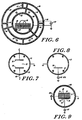
- Fig. 6 illustrates a second preferred embodiment of the apparatus for practicing the process of the invention.
- the outer chamber wall 21 may be water-cooled by cooling coils 28, is again formed of metal, much as electrically grounded aluminum or stainless steel, and is of similar dimensions to that illustrated in Fig. 4.
- Mounted within the chamber is an inner concentric cylinder 43 formed of a perforated metal which may be purposely cooled by cooling coils 30, and is supported on insulating support struts 46.
- the spacing between the inner wall of the chamber and the perforated interior cylinder may range typically from 10 cm to 17 cm, where the chamber has an I.D. of 96.44 centimeters (36 inches).
- a second metallic perforated cylinder 41 is concentrically mounted intermediate between the inner perforated cylinder 43 and the inner wall of the chamber and may also be cooled by cooling coils 19.
- This second perforated cylinder is supported on insulating struts 47 and is spaced typically 4 to 7 cm away from the inner perforated cylinder 43.
- the insulator struts may again be formed of a ceramic material.
- Mounted on the interior of the inner concentric cylinder 43 are support rails 27 for carrying a wire basket which would contain the materials to be sterilized.
- Both the outer chamber wall 21 and the inner perforated cylinder 43 are electrically connected to point of potential reference (ground). Electrical connections would most usually be made through ceramic seal feedthroughs 48 and 49.
- the intermediate cylinder 41 is electrically connected to one side of the RF power supply 22, the other side of which is connected to the point of potential reference.
- gas diffusion tubes 35 may be employed to provide the gas to the interior of the chamber.
- each tube would have holes of diameter between 0.5 mm and 1.5 mm, spaced approximately 2.54 centimeters (1 inch) apart along its length. The hole diameters closer to the gas source would be of the smaller diameter.
- gas inlets may be provided behind chamber door 39. As indicated in the embodiments of Figs.
- the perforated inner cylinders may be open-ended at both ends or, may be closed with the same perforated stock as is used to form the cylinder(s).
- the sterilization chambers shown in Figs. 4, 5 and 6 may be connected to a microwave discharge source, typically operating at 2540MHz, in lieu of an RF energy source.
- the concentric perforated metallic cylinder(s) may be replaced by a single perforated shield in accordance with the operational description given for Fig. 3.
- Fig. 7 illustrates a third preferred embodiment of the apparatus for practicing the process of the invention.
- the outer chamber wall 21 is again formed of metal, such as aluminum or stainless steel, and is of similar dimensions to that illustrated in Fig. 4.
- Mounted within the chamber are two planar, metallic, electrodes 50 and 51, preferably constructed of aluminum which may be coated with insulating aluminum oxide.
- the gap 52 between electrodes 50 and 51 is adjustable by virtue of the movable bottom electrode 50.
- Terminals A and B are connected to the electrodes via an insulating feedthrough 48.
- terminals may be connected to an RF source (not shown) in such a way that when terminal B is connected to a ground potential, terminal A must be connected to the RF source, or vice versa, providing for an electrical symmetrical configuration.
- the work load to be sterilized is placed on lower electrode 50.
- the electrode material may also be made of the perforated stock previously mentioned. However, it is desirable to have the RF-powered electrode made of solid stock to enable very efficient water cooling of that electrode.
- the bottom electrode may also be made of solid stock to enable a cooler surface upon which the work load to be sterilized will be placed. This chamber will commonly be evacuated to 10 microns Hg to 100 microns Hg before gas introduction via the perforated gas diffusion tubes 35.
- Practical device sterilization can be obtained with process parameters for gas flow rates in the range 20 cubic centimeters per minute (scc/m) to 3000 scc/m, corresponding to a total sterilization reaction pressure of 10 microns HG to 5000 microns Hg, at a range of RF power densities of 0.0125 W/cm 3 to 0.08 W/cm 3 .
- Process exposure times will depend on load size and are commonly in the range 2 minutes to 120 minutes.
- Fig. 8 illustrates in diagrammatic form yet another preferred embodiment for practicing the process of the invention.
- the outer wall of chamber 21 is again formed of metal, such as aluminum or stainless steel. maintained at ground potential, and is of similar dimensions to that illustrated in Fig. 4.
- Mounted within the chamber is a single planar, metallic, electrode 50, preferably constructed of aluminum which may be coated with insulating aluminum oxide to reduce RF sputtering.
- This electrode is commonly connected to an RF source in the MHZ range and carries the work load to be sterilized.
- This electrode has commonly a total surface area which is at least four times smaller than the total internal surface area of the grounded chamber, to effect a low plasma potential mode of operation. This arrangement, coupled with low power densities (see below) is conducive to very low sterilization temperatures.
- This electrical configuration is usually referred to as asymmetric and is conducive to generating an extremely uniform plasma glow filling the entire volume of the processing chamber. It is also responsible for the development of a characteristic accelerating potential at the surface of electrode 50, associated with a thin "dark space" through which positive plasma ions will accelerate and impinge on the electrode and the work load it normally carries.
- This process chamber configuration is its ability to render efficient sterilization at relatively low power densities in the range of 0.0125 W/cm 3 0.025 W/cm 3 .
- This configuration is alto easily scalable as a function of work load size.
- This process chamber commonly operates with at least an order of magnitude lower pressure than the pressure for chambers described in Figs. 1 through 7, while the gas dispersion tubes 35 are similar in construction to those previously mentioned.
- electrode 50 may either be hard-anodized or alternatively aluminum oxide spray-coated.
- chamber 21 is water-cooled by cooling coils 28 and contains a perforated metallic enclosure 71 totally surrounding and containing electrode 70.
- This enclosure may be cooled by coolant-recirculating coils 72 and may be connected to a separate RF source 22a, of a different frequency than that of source 22.
- This perforated enclosure may be equipped with an open/close hinging mechanism (not shown) to enable access for material to be sterilized to be placed on electrode 70 contained within enclosure 71.
- RF power applied to electrode 70 which may or may not include a negative DC potential from a separate DC supply, (not shown), will control energy of ion impingement, while RF power applied to the auxiliary perforated enclosure 71, will control active species abundance.
- RF power sources operating at 100 KHz and 13.56 MHZ may be used in the various possible permutations.
- interesting results are obtained by mixing both frequencies while being applied to a single element. Commonly, one frequency has to be applied at a higher power fraction, usually around 90% of the total applied power to the same element.
- Such interesting process results were obtained when the two different frequencies were mixed and applied to electrode 70 in the absence of any auxiliary perforated enclosure.
- the mixed frequency concept also lends itself to low power density sterilization in the range 0.0125 W/cm 3 to 0.025 W/cm 3 , with the advantage of maintaining the overall temperature relatively low (below 50°C), particularly when electrode 70 is water-cooled by cooling coils 74.
- auxiliary perforated enclosure 71 ought to be of high mesh transparency to allow the plasma glow to extend past it and contact electrode 70. Best operating conditions will be obtained for the smallest surface area of this perforated metallic enclosure. In a few instances, this metallic enclosure was connected to ground, yielding effective sterilization data.
- each vial or "Spordex” envelope contained a bacterial strip having an original spore population of not less than 1x10 6 Bacillus Subtilis var Niger per strip, but more commonly in the range 2.2x10 6 spores per strip to 4.0x10 6 spores per strip.
- the strips contained the permeable plastic vials were not brought into contact with the culture solution contained in any of the vials prior to sterilization.
- the vials were placed within the Tyvek/polyethylene bags during the plasma sterilization, alongside devices or instruments to be sterilized. The bags were always sealed during the sterilization process.
- the chamber was first evacuated to an initial low pressure level after the materials (in the bags or pouches) were placed within it.
- the chamber was thereafter filled with the appropriate gas prior to striking the discharge, and the gas continued to flow through the chamber at a controlled rate to establish a steady state sterilization pressure.
- the discharge was initiated by the application of RF or microwave power as indicated.
- the discharge was maintained for a controlled time period at the end of which the power was turned off, the chamber was first evacuated, then backfilled with air through a bacteria retentive filter, and later opened and the samples removed.
- the temperature within the chamber during the process was maintained at less than 70 o C, and more typically around 25 o C to 65 o C, as sensed by an iron-constantan, type "J", thermocouple circuitry and monitored by an analog temperature meter.
- the spore strips in the "Attest" vials where brought into contact with the self-contained culture solution and incubated for 72 hr, at the end of which period microorganism growth or no growth would be indicated by the resultant color of the culture solution.
- the spore strips were submitted to an independent testing laboratory which performed a total plate count on the sample strips using a procedure in which 100 milliliters of sterile deionized water were added to each strip in a sterile whirl-pak bag. The bag was then placed in a lab blender for 10 minutes.
- the initial spare population was 4x10 6 spores/strip.
- Sample was the standard sterilization test pack provided by guidelines of the Association for the Advancement of Medical Instrumentation (AAMI)
- Sterilization test pack employed was according to AAMI guidelines.
- Spore strip was placed in middle of tubing at approximately 45.7 cm (18-inch) from either free end of tubing. The latter was bent into a U-shape and placed within a Tyvek/polyethylene pouch and sealed prior to plasma sterilization.
Landscapes
- Health & Medical Sciences (AREA)
- Physics & Mathematics (AREA)
- Engineering & Computer Science (AREA)
- Plasma & Fusion (AREA)
- Epidemiology (AREA)
- Life Sciences & Earth Sciences (AREA)
- Animal Behavior & Ethology (AREA)
- General Health & Medical Sciences (AREA)
- Public Health (AREA)
- Veterinary Medicine (AREA)
- Apparatus For Disinfection Or Sterilisation (AREA)
- Materials For Medical Uses (AREA)
Abstract
Description
| Fraction A | Fraction B |
| O2(92 - 97%) | CF4(3-8%) |
| [O2(40%)-He(60%)] | CF4(0.25 - 3%) |
| [O2(8%) - CF4(92%)] | He(80%) |
| [O2(17%) - CF4(83%)] | He(80%) |
| [O2(83%) - CF4(17%)] | He(80%) |
| [O2(92%) - CF4(8%)] | He(80%) |
| FlowRate (scc/min) | Pressure NT/m2 (torr) | Exposure (min) | Resultant Microbial Count (CFUs) | Percent Kill (%) |
| 30 | 26.7 (0.20) | 20 | 5.8x10⁵ | 77.6923 |
| 30 | 29.3 (0.22) | 45 | <10 | 99.9999 |
| Exposure Time (min) | Dry O2 | Moist O2 |
| 30 | 4 vials - total kill | 9 vials - |
| 45 | 6 vials - total kill | 10 vials - total kill |
| 60 | 8 vials - total kill | - |
| 75 | 10 vials - total kill | - |
| Dry N2 | Moist N2 | |
| 30 | 0 vials - total kill | 0 vials - |
| 45 | 0 vials - total kill | 0 vials - total kill |
| 60 | 1 vial - total kill | 2 vials - total kill |
| 75 | 2 vials - total kill | 3 vials - total kill |
| Dry Ar | Moist Ar | |
| 30 | 0 vials - total kill | 0 vials - |
| 45 | 0 vials - total kill | 1 vial - total kill |
| 60 | 1 vial - total kill | 2 vials - total kill |
| 75 | 2 vials - total kill | 3 vials - total kill |
| Exposure Time (min) | Dry N2-O2 | Moist N2-O2 |
| 30 | 1 vial - total kill | 1 vial - total kill |
| 45 | 1 vial - total kill | 1 vial total kill |
| 60 | 2 vials - total kill | 3 vials - total kill |
| 75 | 3 vials - total kill | 4 vials total kill |
| Dray Ar-O2 | Moist Ar-O2 | |
| 30 | 1 vial - total kill | 1 vial - total kill |
| 45 | 1 vial - total kill | 2 vials - total kill |
| 60 | 3 vials - total kill | 4 vials - total kill |
| 75 | 4 vials - total kill | 5 vials - total kill |
Claims (7)
- Apparatus for sterilization and treatment of medical and dental devices and materials in a gas plasma comprising,a gas-tight confining chamber formed with a metallic wall connected to a point of potantial reference,a first perforated metallic electrode positioned within and spaced from said chamber wall,means for electrically connecting said chamber wall to a point of potential referencemeans for applying an RF voltage between said perforated electrode and said point of potential reference,means for evacuating said qas-confining chamber, andmeans for flowing gas through said chamber
characterized by said first perforated metallic electrode being fluid cooled. - Apparatus in accordance with claim 1 wherein said cantining chamber is fluid cooled.
- A method for sterilization and treatment of medical and dental devices and materials comprising the steps of,placing said devices and materials within a first metallic perforated electrode, said electrode being positioned within, and spaced from a gas tight confining chamber and characterized in that it is fluid cooled,, said chamber formed with a metallic wall connected to a point of potential reference,evacuating said chamber to a substantially low pressure and introducing a gas into said chamber,initiating an electrical discharge in said gas within said chamber by application of an RF voltage between said internal perforated electrode and said chamber wall, creating a gas plasma accompanied by a substantially field-free and glowless volume within the perforated electrode containing said devices and materials, whereby said devices and materials are contacted by substantially electrically neutral active species at a temperature below that which would be detrimental to said devices and materials,maintaining said gas plasma for a controlled period of time,maintaining a flow of said gas through said chamber; andwithdrawing said devices and materials from said chamber.
- A method in accordance with claim 3, wherein said gas-tight confining chamber is fluid cooled.
- A method in accordance with claims 3 or 4, wherein said devices and materials are enclosed within sealed pouches formed of gas-permeable material while said pouches containing said materials and devices are within said chamber.
- A method in accordance with any one of claims 3 and 4, wherein said gas is selected from the group consisting of, an oxidizing gas or a reducing gas.
- A method in accordance with any one of claims 3 and 4, wherein said gas comprises one or more of the group of gases consisting of:hydrogen; oxygen nitrogen, hydrogen-oxygen mixtures; hydrogen-oxygen-inert gas mixtures; oxygen-nitrogen mixtures; oxygen-nitrogen-inert gas mixtures; nitrogen-hydrogen mixtures; nitrogen-hydrogen-inert gas mixtures; oxygen-nitrogen-hydrogen mixtures; oxygen-nitrogen-hydrogen-inert gas mixtures; oxygen-helium mixtures; nitrogen-helium mixtures; hydrogen-helium mixtures; oxygen-organohalogen mixtures; oxygen-organohalogen-inert gas mixtures; oxygen-organohalogen-nitrogen mixtures; oxygen-inorganic halogen mixtures; oxygen-inorganic halogen-inert gas mixtures; oxygen-inorganic halogen-nitrogen mixtures; oxygen inorganic oxyhalogenated compound mixtures; oxygen-inorganic oxyhalogenated compound-inert gas mixtures; oxygen-inorganic oxyhalogenated compound-nitrogen mixtures, helium, argon, helium-argon mixtures.
Applications Claiming Priority (3)
| Application Number | Priority Date | Filing Date | Title |
|---|---|---|---|
| US07/331,438 US4976920A (en) | 1987-07-14 | 1989-03-31 | Process for dry sterilization of medical devices and materials |
| US331438 | 1989-03-31 | ||
| PCT/US1990/001748 WO1990011784A1 (en) | 1989-03-31 | 1990-03-28 | Process and apparatus for dry sterilization of medical devices and materials |
Publications (3)
| Publication Number | Publication Date |
|---|---|
| EP0465569A1 EP0465569A1 (en) | 1992-01-15 |
| EP0465569A4 EP0465569A4 (en) | 1992-03-11 |
| EP0465569B1 true EP0465569B1 (en) | 1998-06-17 |
Family
ID=23293970
Family Applications (1)
| Application Number | Title | Priority Date | Filing Date |
|---|---|---|---|
| EP90905946A Expired - Lifetime EP0465569B1 (en) | 1989-03-31 | 1990-03-28 | Process and apparatus for dry sterilization of medical devices and materials |
Country Status (7)
| Country | Link |
|---|---|
| US (1) | US4976920A (en) |
| EP (1) | EP0465569B1 (en) |
| AT (1) | ATE167401T1 (en) |
| AU (1) | AU5416490A (en) |
| CA (1) | CA2013533C (en) |
| DE (1) | DE69032427T2 (en) |
| WO (1) | WO1990011784A1 (en) |
Families Citing this family (54)
| Publication number | Priority date | Publication date | Assignee | Title |
|---|---|---|---|---|
| US5302343A (en) * | 1987-02-25 | 1994-04-12 | Adir Jacob | Process for dry sterilization of medical devices and materials |
| US5171525A (en) * | 1987-02-25 | 1992-12-15 | Adir Jacob | Process and apparatus for dry sterilization of medical devices and materials |
| US5200158A (en) * | 1987-02-25 | 1993-04-06 | Adir Jacob | Process and apparatus for dry sterilization of medical devices and materials |
| JPH02279160A (en) * | 1989-03-08 | 1990-11-15 | Abtox Inc | Plasma sterilization method and plasma sterilizer |
| US5413759A (en) * | 1989-03-08 | 1995-05-09 | Abtox, Inc. | Plasma sterilizer and method |
| US5288460A (en) * | 1989-03-08 | 1994-02-22 | Abtox, Inc. | Plasma cycling sterilizing process |
| US5593649A (en) * | 1989-03-08 | 1997-01-14 | Abtox, Inc. | Canister with plasma gas mixture for sterilizer |
| US5413760A (en) * | 1989-03-08 | 1995-05-09 | Abtox, Inc. | Plasma sterilizer and method |
| US5472664A (en) * | 1989-03-08 | 1995-12-05 | Abtox, Inc. | Plasma gas mixture for sterilizer and method |
| US5650693A (en) * | 1989-03-08 | 1997-07-22 | Abtox, Inc. | Plasma sterilizer apparatus using a non-flammable mixture of hydrogen and oxygen |
| US5645796A (en) * | 1990-08-31 | 1997-07-08 | Abtox, Inc. | Process for plasma sterilizing with pulsed antimicrobial agent treatment |
| US5244629A (en) * | 1990-08-31 | 1993-09-14 | Caputo Ross A | Plasma sterilizing process with pulsed antimicrobial agent pretreatment |
| US5325020A (en) * | 1990-09-28 | 1994-06-28 | Abtox, Inc. | Circular waveguide plasma microwave sterilizer apparatus |
| US5247179A (en) * | 1990-10-18 | 1993-09-21 | Hiroshi Tachibana | Activation energy providing device |
| US5376332A (en) * | 1991-02-06 | 1994-12-27 | Abtox, Inc. | Plasma sterilizing with downstream oxygen addition |
| US5200146A (en) * | 1991-02-26 | 1993-04-06 | Air Techniques, Inc. | Apparatus for effecting plasma sterilization |
| GB2253144B (en) * | 1991-03-01 | 1995-07-05 | Atomic Energy Authority Uk | Gas sterilisation |
| DE4108766C2 (en) * | 1991-03-18 | 1996-08-01 | Knapp Guenter Univ Prof Dipl I | Device for heating substances under high pressure in the microwave field |
| US5834386A (en) * | 1994-06-27 | 1998-11-10 | Kimberly-Clark Worldwide, Inc. | Nonwoven barrier |
| US5505056A (en) * | 1994-10-21 | 1996-04-09 | Jones; Steven M. | Method and apparatus for sterilization |
| US5681322A (en) * | 1994-11-14 | 1997-10-28 | Meadox Medicals, Inc. | Gas sterilizable intraluminal delivery system |
| US6159422A (en) * | 1994-12-29 | 2000-12-12 | Graves' Trust Group | Methods and apparatus for the treatment of hazardous biological waste materials |
| US5633424A (en) * | 1994-12-29 | 1997-05-27 | Graves; Clinton G. | Device and methods for plasma sterilization |
| ZA965786B (en) * | 1995-07-19 | 1997-01-27 | Kimberly Clark Co | Nonwoven barrier and method of making the same |
| US5698168A (en) * | 1995-11-01 | 1997-12-16 | Chorus Corporation | Unibody gas plasma source technology |
| US6006387A (en) * | 1995-11-30 | 1999-12-28 | Cyclo3Pss Textile Systems, Inc. | Cold water ozone disinfection |
| US5763382A (en) * | 1996-01-03 | 1998-06-09 | Cyclo3Pss Textile Systems, Inc. | Cold water wash formula |
| AU1641097A (en) * | 1996-03-27 | 1997-10-02 | Ethicon Inc. | Process for cleaning surgical needles |
| AU713054B2 (en) * | 1996-03-27 | 1999-11-25 | Ethicon Inc. | Process for blackening surgical needles |
| US5928527A (en) * | 1996-04-15 | 1999-07-27 | The Boeing Company | Surface modification using an atmospheric pressure glow discharge plasma source |
| US20030118491A1 (en) * | 1998-08-26 | 2003-06-26 | Frieze Marcia A. | Filtered gas plasma sterilization container with improved circulation |
| US6458398B1 (en) | 1999-10-18 | 2002-10-01 | Eco Pure Food Safety Systems, Inc. | Cold water disinfection of foods |
| DE60125520T2 (en) * | 2000-02-23 | 2007-10-18 | Case Medical, Inc. | STERILIZATION TANK WITH FILTERED GAS PLASMA AND IMPROVED CIRCULATION |
| US20020098111A1 (en) * | 2000-12-04 | 2002-07-25 | Nguyen Nick N. | Vaporizer |
| DE10210898A1 (en) * | 2002-03-08 | 2003-09-25 | Ruediger Haaga Gmbh | Device for sterilizing objects |
| US7095019B1 (en) | 2003-05-30 | 2006-08-22 | Chem-Space Associates, Inc. | Remote reagent chemical ionization source |
| JP4329403B2 (en) * | 2003-05-19 | 2009-09-09 | 東京エレクトロン株式会社 | Plasma processing equipment |
| US7449053B2 (en) | 2003-07-18 | 2008-11-11 | David Richard Hallam | Air filtration device |
| US7164095B2 (en) * | 2004-07-07 | 2007-01-16 | Noritsu Koki Co., Ltd. | Microwave plasma nozzle with enhanced plume stability and heating efficiency |
| US7806077B2 (en) | 2004-07-30 | 2010-10-05 | Amarante Technologies, Inc. | Plasma nozzle array for providing uniform scalable microwave plasma generation |
| US20060021980A1 (en) * | 2004-07-30 | 2006-02-02 | Lee Sang H | System and method for controlling a power distribution within a microwave cavity |
| US7189939B2 (en) * | 2004-09-01 | 2007-03-13 | Noritsu Koki Co., Ltd. | Portable microwave plasma discharge unit |
| US7271363B2 (en) * | 2004-09-01 | 2007-09-18 | Noritsu Koki Co., Ltd. | Portable microwave plasma systems including a supply line for gas and microwaves |
| US20060052883A1 (en) * | 2004-09-08 | 2006-03-09 | Lee Sang H | System and method for optimizing data acquisition of plasma using a feedback control module |
| US7138626B1 (en) | 2005-05-05 | 2006-11-21 | Eai Corporation | Method and device for non-contact sampling and detection |
| US7568401B1 (en) | 2005-06-20 | 2009-08-04 | Science Applications International Corporation | Sample tube holder |
| US7576322B2 (en) * | 2005-11-08 | 2009-08-18 | Science Applications International Corporation | Non-contact detector system with plasma ion source |
| US8123396B1 (en) | 2007-05-16 | 2012-02-28 | Science Applications International Corporation | Method and means for precision mixing |
| US8008617B1 (en) | 2007-12-28 | 2011-08-30 | Science Applications International Corporation | Ion transfer device |
| US8071957B1 (en) | 2009-03-10 | 2011-12-06 | Science Applications International Corporation | Soft chemical ionization source |
| ITNA20090066A1 (en) * | 2009-10-27 | 2011-04-28 | Adiramef S R L | SYSTEM FOR ABSOLUTE STERILIZATION WITH CYCLE COMBINED WITH SATURATED VAPOR AND OXYGEN PLASMA GAS. |
| WO2011110191A1 (en) * | 2010-03-10 | 2011-09-15 | Max-Planck-Gesellschaft zur Förderung der Wissenschaften e. V. | Method and arrangement for treating an object with a low- temperature plasma |
| CN115671329B (en) * | 2022-11-10 | 2024-04-12 | 湖南湘华华大生物科技有限公司 | Irradiation sterilization method of closed negative pressure flushing suction device |
| CN118022015B (en) * | 2023-12-29 | 2024-08-30 | 江苏长江药业有限公司 | Purification sterilization device is used in injection production |
Family Cites Families (43)
| Publication number | Priority date | Publication date | Assignee | Title |
|---|---|---|---|---|
| US3876373A (en) * | 1968-03-18 | 1975-04-08 | Nicholas D Glyptis | Method and apparatus for modifying the reproductive mechanism of organisms |
| US3701628A (en) * | 1970-02-25 | 1972-10-31 | Little Inc A | Treatment of surface with low-pressure plasmas |
| US3753651A (en) * | 1970-08-27 | 1973-08-21 | Wave Energy Systems | Method and apparatus for surface sterilization |
| US3757733A (en) * | 1971-10-27 | 1973-09-11 | Texas Instruments Inc | Radial flow reactor |
| US3851436A (en) * | 1971-12-13 | 1974-12-03 | Boeing Co | Sterilizing and packaging process utilizing gas plasma |
| USRE30505E (en) * | 1972-05-12 | 1981-02-03 | Lfe Corporation | Process and material for manufacturing semiconductor devices |
| US4026742A (en) * | 1972-11-22 | 1977-05-31 | Katsuhiro Fujino | Plasma etching process for making a microcircuit device |
| US3948601A (en) * | 1972-12-11 | 1976-04-06 | The Boeing Company | Sterilizing process and apparatus utilizing gas plasma |
| US3971684A (en) * | 1973-12-03 | 1976-07-27 | Hewlett-Packard Company | Etching thin film circuits and semiconductor chips |
| US3923568A (en) * | 1974-01-14 | 1975-12-02 | Int Plasma Corp | Dry plasma process for etching noble metal |
| US3951709A (en) * | 1974-02-28 | 1976-04-20 | Lfe Corporation | Process and material for semiconductor photomask fabrication |
| US4028155A (en) * | 1974-02-28 | 1977-06-07 | Lfe Corporation | Process and material for manufacturing thin film integrated circuits |
| US4362632A (en) * | 1974-08-02 | 1982-12-07 | Lfe Corporation | Gas discharge apparatus |
| US3879597A (en) * | 1974-08-16 | 1975-04-22 | Int Plasma Corp | Plasma etching device and process |
| US3994793A (en) * | 1975-05-22 | 1976-11-30 | International Business Machines Corporation | Reactive ion etching of aluminum |
| US4341592A (en) * | 1975-08-04 | 1982-07-27 | Texas Instruments Incorporated | Method for removing photoresist layer from substrate by ozone treatment |
| GB1499857A (en) * | 1975-09-18 | 1978-02-01 | Standard Telephones Cables Ltd | Glow discharge etching |
| US4030967A (en) * | 1976-08-16 | 1977-06-21 | Northern Telecom Limited | Gaseous plasma etching of aluminum and aluminum oxide |
| JPS53142949A (en) * | 1977-05-20 | 1978-12-13 | Origin Electric Co Ltd | Active gas plasma arc torch and its manipulation method |
| US4207286A (en) * | 1978-03-16 | 1980-06-10 | Biophysics Research & Consulting Corporation | Seeded gas plasma sterilization method |
| JPS54158343A (en) * | 1978-06-05 | 1979-12-14 | Hitachi Ltd | Dry etching method for al and al alloy |
| US4182646A (en) * | 1978-07-27 | 1980-01-08 | John Zajac | Process of etching with plasma etch gas |
| US4208241A (en) * | 1978-07-31 | 1980-06-17 | Bell Telephone Laboratories, Incorporated | Device fabrication by plasma etching |
| US4211601A (en) * | 1978-07-31 | 1980-07-08 | Bell Telephone Laboratories, Incorporated | Device fabrication by plasma etching |
| US4256534A (en) * | 1978-07-31 | 1981-03-17 | Bell Telephone Laboratories, Incorporated | Device fabrication by plasma etching |
| US4226665A (en) * | 1978-07-31 | 1980-10-07 | Bell Telephone Laboratories, Incorporated | Device fabrication by plasma etching |
| US4229247A (en) * | 1978-12-26 | 1980-10-21 | International Business Machines Corporation | Glow discharge etching process for chromium |
| US4214946A (en) * | 1979-02-21 | 1980-07-29 | International Business Machines Corporation | Selective reactive ion etching of polysilicon against SiO2 utilizing SF6 -Cl2 -inert gas etchant |
| US4298443A (en) * | 1979-08-09 | 1981-11-03 | Bell Telephone Laboratories, Incorporated | High capacity etching apparatus and method |
| JPS6059994B2 (en) * | 1979-10-09 | 1985-12-27 | 三菱電機株式会社 | Method for forming fine patterns on aluminum film or aluminum alloy film |
| JPS601952B2 (en) * | 1980-01-25 | 1985-01-18 | 三菱電機株式会社 | plasma etching equipment |
| JPS56105483A (en) * | 1980-01-25 | 1981-08-21 | Mitsubishi Electric Corp | Dry etching device |
| US4255230A (en) * | 1980-02-22 | 1981-03-10 | Eaton Corporation | Plasma etching process |
| US4264409A (en) * | 1980-03-17 | 1981-04-28 | International Business Machines Corporation | Contamination-free selective reactive ion etching or polycrystalline silicon against silicon dioxide |
| US4321232B1 (en) * | 1980-03-25 | 1997-12-09 | Abtox Inc | Package and sterilizing process for same |
| US4314875A (en) * | 1980-05-13 | 1982-02-09 | Bell Telephone Laboratories, Incorporated | Device fabrication by plasma etching |
| US4348357A (en) * | 1980-12-12 | 1982-09-07 | Motorola, Inc. | Plasma pressure pulse sterilization |
| US4353777A (en) * | 1981-04-20 | 1982-10-12 | Lfe Corporation | Selective plasma polysilicon etching |
| US4505782A (en) * | 1983-03-25 | 1985-03-19 | Lfe Corporation | Plasma reactive ion etching of aluminum and aluminum alloys |
| US4569895A (en) * | 1984-10-30 | 1986-02-11 | Minnesota Mining And Manufacturing Company | Charge transfer media and process for making thereof |
| US4756882A (en) * | 1985-06-21 | 1988-07-12 | Surgikos Inc. | Hydrogen peroxide plasma sterilization system |
| US4643876A (en) * | 1985-06-21 | 1987-02-17 | Surgikos, Inc. | Hydrogen peroxide plasma sterilization system |
| US4818488A (en) * | 1987-02-25 | 1989-04-04 | Adir Jacob | Process and apparatus for dry sterilization of medical devices and materials |
-
1989
- 1989-03-31 US US07/331,438 patent/US4976920A/en not_active Expired - Fee Related
-
1990
- 1990-03-28 DE DE69032427T patent/DE69032427T2/en not_active Expired - Fee Related
- 1990-03-28 WO PCT/US1990/001748 patent/WO1990011784A1/en active IP Right Grant
- 1990-03-28 AU AU54164/90A patent/AU5416490A/en not_active Abandoned
- 1990-03-28 EP EP90905946A patent/EP0465569B1/en not_active Expired - Lifetime
- 1990-03-28 AT AT90905946T patent/ATE167401T1/en not_active IP Right Cessation
- 1990-03-30 CA CA002013533A patent/CA2013533C/en not_active Expired - Lifetime
Also Published As
| Publication number | Publication date |
|---|---|
| AU5416490A (en) | 1990-11-05 |
| EP0465569A1 (en) | 1992-01-15 |
| WO1990011784A1 (en) | 1990-10-18 |
| ATE167401T1 (en) | 1998-07-15 |
| EP0465569A4 (en) | 1992-03-11 |
| DE69032427T2 (en) | 1999-02-11 |
| CA2013533A1 (en) | 1990-09-30 |
| US4976920A (en) | 1990-12-11 |
| DE69032427D1 (en) | 1998-07-23 |
| CA2013533C (en) | 1999-07-27 |
Similar Documents
| Publication | Publication Date | Title |
|---|---|---|
| EP0465569B1 (en) | Process and apparatus for dry sterilization of medical devices and materials | |
| US5451368A (en) | Process and apparatus for dry sterilization of medical devices and materials | |
| US5200158A (en) | Process and apparatus for dry sterilization of medical devices and materials | |
| US5171525A (en) | Process and apparatus for dry sterilization of medical devices and materials | |
| EP0303682B1 (en) | Process for dry sterilization of medical devices and materials | |
| US4898715A (en) | Process and apparatus for dry sterilization of medical devices and materials | |
| US4931261A (en) | Apparatus for dry sterilization of medical devices and materials | |
| US4917586A (en) | Process for dry sterilization of medical devices and materials | |
| US6149878A (en) | Process for dry sterilization of medical devices and materials | |
| US5741460A (en) | Process for dry sterilization of medical devices and materials | |
| US4943417A (en) | Apparatus for dry sterilization of medical devices and materials | |
| US5087418A (en) | Process for dry sterilization of medical devices and materials | |
| US5115166A (en) | Plasma sterilizer and method | |
| US5084239A (en) | Plasma sterilizing process with pulsed antimicrobial agent treatment | |
| US5413759A (en) | Plasma sterilizer and method | |
| US4909995A (en) | Process and apparatus for dry sterilization of medical devices and materials | |
| EP0048258A4 (en) | Package and sterilizing process for same. | |
| US5472664A (en) | Plasma gas mixture for sterilizer and method | |
| AU6169596A (en) | Process and apparatus for dry sterilization of medical devices and materials | |
| CA1334330C (en) | Process and apparatus for dry sterilization of medical devices and materials | |
| JPH08119236A (en) | Sterilizing method |
Legal Events
| Date | Code | Title | Description |
|---|---|---|---|
| PUAI | Public reference made under article 153(3) epc to a published international application that has entered the european phase |
Free format text: ORIGINAL CODE: 0009012 |
|
| 17P | Request for examination filed |
Effective date: 19911019 |
|
| AK | Designated contracting states |
Kind code of ref document: A1 Designated state(s): AT BE CH DE DK ES FR GB IT LI LU NL SE |
|
| A4 | Supplementary search report drawn up and despatched |
Effective date: 19920120 |
|
| AK | Designated contracting states |
Kind code of ref document: A4 Designated state(s): AT BE CH DE DK ES FR GB IT LI LU NL SE |
|
| 17Q | First examination report despatched |
Effective date: 19950120 |
|
| GRAG | Despatch of communication of intention to grant |
Free format text: ORIGINAL CODE: EPIDOS AGRA |
|
| GRAG | Despatch of communication of intention to grant |
Free format text: ORIGINAL CODE: EPIDOS AGRA |
|
| GRAH | Despatch of communication of intention to grant a patent |
Free format text: ORIGINAL CODE: EPIDOS IGRA |
|
| GRAH | Despatch of communication of intention to grant a patent |
Free format text: ORIGINAL CODE: EPIDOS IGRA |
|
| GRAA | (expected) grant |
Free format text: ORIGINAL CODE: 0009210 |
|
| AK | Designated contracting states |
Kind code of ref document: B1 Designated state(s): AT BE CH DE DK ES FR GB IT LI LU NL SE |
|
| PG25 | Lapsed in a contracting state [announced via postgrant information from national office to epo] |
Ref country code: IT Free format text: LAPSE BECAUSE OF FAILURE TO SUBMIT A TRANSLATION OF THE DESCRIPTION OR TO PAY THE FEE WITHIN THE PRE;WARNING: LAPSES OF ITALIAN PATENTS WITH EFFECTIVE DATE BEFORE 2007 MAY HAVE OCCURRED AT ANY TIME BEFORE 2007. THE CORRECT EFFECTIVE DATE MAY BE DIFFERENT FROM THE ONE RECORDED.SCRIBED TIME-LIMIT Effective date: 19980617 Ref country code: ES Free format text: THE PATENT HAS BEEN ANNULLED BY A DECISION OF A NATIONAL AUTHORITY Effective date: 19980617 Ref country code: LI Free format text: LAPSE BECAUSE OF FAILURE TO SUBMIT A TRANSLATION OF THE DESCRIPTION OR TO PAY THE FEE WITHIN THE PRESCRIBED TIME-LIMIT Effective date: 19980617 Ref country code: NL Free format text: LAPSE BECAUSE OF FAILURE TO SUBMIT A TRANSLATION OF THE DESCRIPTION OR TO PAY THE FEE WITHIN THE PRESCRIBED TIME-LIMIT Effective date: 19980617 Ref country code: AT Free format text: LAPSE BECAUSE OF FAILURE TO SUBMIT A TRANSLATION OF THE DESCRIPTION OR TO PAY THE FEE WITHIN THE PRESCRIBED TIME-LIMIT Effective date: 19980617 Ref country code: BE Free format text: LAPSE BECAUSE OF FAILURE TO SUBMIT A TRANSLATION OF THE DESCRIPTION OR TO PAY THE FEE WITHIN THE PRESCRIBED TIME-LIMIT Effective date: 19980617 Ref country code: CH Free format text: LAPSE BECAUSE OF FAILURE TO SUBMIT A TRANSLATION OF THE DESCRIPTION OR TO PAY THE FEE WITHIN THE PRESCRIBED TIME-LIMIT Effective date: 19980617 |
|
| REF | Corresponds to: |
Ref document number: 167401 Country of ref document: AT Date of ref document: 19980715 Kind code of ref document: T |
|
| REG | Reference to a national code |
Ref country code: CH Ref legal event code: EP |
|
| REF | Corresponds to: |
Ref document number: 69032427 Country of ref document: DE Date of ref document: 19980723 |
|
| PG25 | Lapsed in a contracting state [announced via postgrant information from national office to epo] |
Ref country code: SE Free format text: LAPSE BECAUSE OF FAILURE TO SUBMIT A TRANSLATION OF THE DESCRIPTION OR TO PAY THE FEE WITHIN THE PRESCRIBED TIME-LIMIT Effective date: 19980917 Ref country code: DK Free format text: LAPSE BECAUSE OF FAILURE TO SUBMIT A TRANSLATION OF THE DESCRIPTION OR TO PAY THE FEE WITHIN THE PRESCRIBED TIME-LIMIT Effective date: 19980917 |
|
| ET | Fr: translation filed | ||
| NLV1 | Nl: lapsed or annulled due to failure to fulfill the requirements of art. 29p and 29m of the patents act | ||
| REG | Reference to a national code |
Ref country code: CH Ref legal event code: PL |
|
| PG25 | Lapsed in a contracting state [announced via postgrant information from national office to epo] |
Ref country code: LU Free format text: LAPSE BECAUSE OF NON-PAYMENT OF DUE FEES Effective date: 19990328 |
|
| PLBE | No opposition filed within time limit |
Free format text: ORIGINAL CODE: 0009261 |
|
| STAA | Information on the status of an ep patent application or granted ep patent |
Free format text: STATUS: NO OPPOSITION FILED WITHIN TIME LIMIT |
|
| 26N | No opposition filed | ||
| REG | Reference to a national code |
Ref country code: GB Ref legal event code: IF02 |
|
| PGFP | Annual fee paid to national office [announced via postgrant information from national office to epo] |
Ref country code: GB Payment date: 20080326 Year of fee payment: 19 |
|
| PGFP | Annual fee paid to national office [announced via postgrant information from national office to epo] |
Ref country code: DE Payment date: 20080429 Year of fee payment: 19 |
|
| PGFP | Annual fee paid to national office [announced via postgrant information from national office to epo] |
Ref country code: FR Payment date: 20080319 Year of fee payment: 19 |
|
| GBPC | Gb: european patent ceased through non-payment of renewal fee |
Effective date: 20090328 |
|
| REG | Reference to a national code |
Ref country code: FR Ref legal event code: ST Effective date: 20091130 |
|
| PG25 | Lapsed in a contracting state [announced via postgrant information from national office to epo] |
Ref country code: DE Free format text: LAPSE BECAUSE OF NON-PAYMENT OF DUE FEES Effective date: 20091001 |
|
| PG25 | Lapsed in a contracting state [announced via postgrant information from national office to epo] |
Ref country code: GB Free format text: LAPSE BECAUSE OF NON-PAYMENT OF DUE FEES Effective date: 20090328 Ref country code: FR Free format text: LAPSE BECAUSE OF NON-PAYMENT OF DUE FEES Effective date: 20091123 |