EP0465473B1 - Valve - Google Patents
Valve Download PDFInfo
- Publication number
- EP0465473B1 EP0465473B1 EP90903229A EP90903229A EP0465473B1 EP 0465473 B1 EP0465473 B1 EP 0465473B1 EP 90903229 A EP90903229 A EP 90903229A EP 90903229 A EP90903229 A EP 90903229A EP 0465473 B1 EP0465473 B1 EP 0465473B1
- Authority
- EP
- European Patent Office
- Prior art keywords
- valve
- valve housing
- passage
- closed
- sealing
- Prior art date
- Legal status (The legal status is an assumption and is not a legal conclusion. Google has not performed a legal analysis and makes no representation as to the accuracy of the status listed.)
- Expired - Lifetime
Links
- 238000007789 sealing Methods 0.000 claims abstract description 18
- 238000012423 maintenance Methods 0.000 claims abstract description 10
- 239000012530 fluid Substances 0.000 claims description 13
- 230000004308 accommodation Effects 0.000 claims 1
- 230000001276 controlling effect Effects 0.000 description 3
- 238000012856 packing Methods 0.000 description 2
- 230000001105 regulatory effect Effects 0.000 description 2
- 238000013461 design Methods 0.000 description 1
- 229930195733 hydrocarbon Natural products 0.000 description 1
- 150000002430 hydrocarbons Chemical class 0.000 description 1
- 238000007689 inspection Methods 0.000 description 1
- 238000000034 method Methods 0.000 description 1
- 238000012544 monitoring process Methods 0.000 description 1
- 230000000284 resting effect Effects 0.000 description 1
- -1 subsea pipelines Chemical class 0.000 description 1
- 238000011144 upstream manufacturing Methods 0.000 description 1
- XLYOFNOQVPJJNP-UHFFFAOYSA-N water Substances O XLYOFNOQVPJJNP-UHFFFAOYSA-N 0.000 description 1
Images




Classifications
-
- F—MECHANICAL ENGINEERING; LIGHTING; HEATING; WEAPONS; BLASTING
- F16—ENGINEERING ELEMENTS AND UNITS; GENERAL MEASURES FOR PRODUCING AND MAINTAINING EFFECTIVE FUNCTIONING OF MACHINES OR INSTALLATIONS; THERMAL INSULATION IN GENERAL
- F16K—VALVES; TAPS; COCKS; ACTUATING-FLOATS; DEVICES FOR VENTING OR AERATING
- F16K5/00—Plug valves; Taps or cocks comprising only cut-off apparatus having at least one of the sealing faces shaped as a more or less complete surface of a solid of revolution, the opening and closing movement being predominantly rotary
- F16K5/06—Plug valves; Taps or cocks comprising only cut-off apparatus having at least one of the sealing faces shaped as a more or less complete surface of a solid of revolution, the opening and closing movement being predominantly rotary with plugs having spherical surfaces; Packings therefor
- F16K5/0605—Plug valves; Taps or cocks comprising only cut-off apparatus having at least one of the sealing faces shaped as a more or less complete surface of a solid of revolution, the opening and closing movement being predominantly rotary with plugs having spherical surfaces; Packings therefor with particular plug arrangements, e.g. particular shape or built-in means
-
- F—MECHANICAL ENGINEERING; LIGHTING; HEATING; WEAPONS; BLASTING
- F16—ENGINEERING ELEMENTS AND UNITS; GENERAL MEASURES FOR PRODUCING AND MAINTAINING EFFECTIVE FUNCTIONING OF MACHINES OR INSTALLATIONS; THERMAL INSULATION IN GENERAL
- F16K—VALVES; TAPS; COCKS; ACTUATING-FLOATS; DEVICES FOR VENTING OR AERATING
- F16K3/00—Gate valves or sliding valves, i.e. cut-off apparatus with closing members having a sliding movement along the seat for opening and closing
- F16K3/02—Gate valves or sliding valves, i.e. cut-off apparatus with closing members having a sliding movement along the seat for opening and closing with flat sealing faces; Packings therefor
- F16K3/04—Gate valves or sliding valves, i.e. cut-off apparatus with closing members having a sliding movement along the seat for opening and closing with flat sealing faces; Packings therefor with pivoted closure members
- F16K3/06—Gate valves or sliding valves, i.e. cut-off apparatus with closing members having a sliding movement along the seat for opening and closing with flat sealing faces; Packings therefor with pivoted closure members in the form of closure plates arranged between supply and discharge passages
- F16K3/08—Gate valves or sliding valves, i.e. cut-off apparatus with closing members having a sliding movement along the seat for opening and closing with flat sealing faces; Packings therefor with pivoted closure members in the form of closure plates arranged between supply and discharge passages with circular plates rotatable around their centres
- F16K3/085—Gate valves or sliding valves, i.e. cut-off apparatus with closing members having a sliding movement along the seat for opening and closing with flat sealing faces; Packings therefor with pivoted closure members in the form of closure plates arranged between supply and discharge passages with circular plates rotatable around their centres the axis of supply passage and the axis of discharge passage being coaxial and parallel to the axis of rotation of the plates
-
- F—MECHANICAL ENGINEERING; LIGHTING; HEATING; WEAPONS; BLASTING
- F16—ENGINEERING ELEMENTS AND UNITS; GENERAL MEASURES FOR PRODUCING AND MAINTAINING EFFECTIVE FUNCTIONING OF MACHINES OR INSTALLATIONS; THERMAL INSULATION IN GENERAL
- F16K—VALVES; TAPS; COCKS; ACTUATING-FLOATS; DEVICES FOR VENTING OR AERATING
- F16K49/00—Means in or on valves for heating or cooling
-
- Y—GENERAL TAGGING OF NEW TECHNOLOGICAL DEVELOPMENTS; GENERAL TAGGING OF CROSS-SECTIONAL TECHNOLOGIES SPANNING OVER SEVERAL SECTIONS OF THE IPC; TECHNICAL SUBJECTS COVERED BY FORMER USPC CROSS-REFERENCE ART COLLECTIONS [XRACs] AND DIGESTS
- Y10—TECHNICAL SUBJECTS COVERED BY FORMER USPC
- Y10T—TECHNICAL SUBJECTS COVERED BY FORMER US CLASSIFICATION
- Y10T137/00—Fluid handling
- Y10T137/598—With repair, tapping, assembly, or disassembly means
- Y10T137/6031—Assembling or disassembling rotary valve
- Y10T137/6035—Rotary ball valve
- Y10T137/6038—Particular valve seat or interface seal
- Y10T137/6041—Replaceable
-
- Y—GENERAL TAGGING OF NEW TECHNOLOGICAL DEVELOPMENTS; GENERAL TAGGING OF CROSS-SECTIONAL TECHNOLOGIES SPANNING OVER SEVERAL SECTIONS OF THE IPC; TECHNICAL SUBJECTS COVERED BY FORMER USPC CROSS-REFERENCE ART COLLECTIONS [XRACs] AND DIGESTS
- Y10—TECHNICAL SUBJECTS COVERED BY FORMER USPC
- Y10T—TECHNICAL SUBJECTS COVERED BY FORMER US CLASSIFICATION
- Y10T137/00—Fluid handling
- Y10T137/598—With repair, tapping, assembly, or disassembly means
- Y10T137/6089—With mechanical movement between actuator and valve
- Y10T137/6099—Gear type
-
- Y—GENERAL TAGGING OF NEW TECHNOLOGICAL DEVELOPMENTS; GENERAL TAGGING OF CROSS-SECTIONAL TECHNOLOGIES SPANNING OVER SEVERAL SECTIONS OF THE IPC; TECHNICAL SUBJECTS COVERED BY FORMER USPC CROSS-REFERENCE ART COLLECTIONS [XRACs] AND DIGESTS
- Y10—TECHNICAL SUBJECTS COVERED BY FORMER USPC
- Y10T—TECHNICAL SUBJECTS COVERED BY FORMER US CLASSIFICATION
- Y10T137/00—Fluid handling
- Y10T137/8593—Systems
- Y10T137/87917—Flow path with serial valves and/or closures
- Y10T137/88022—One valve head provides seat for other head
- Y10T137/8803—Also carries head of other valve
Definitions
- This invention concerns a device associated with a valve, in particular a rotatable valve comprising an upper part and a lower part which are detachably joined to each other.
- Valves of the kind mentioned above can be made sufficiently large and robust in order to be mounted onto pipelines which transport hydrocarbons, particularly subsea pipelines, but the invention can also be exploited in other environments and in smaller dimensions.
- a ball valve which is intended for connection with a pipeline system which conveys gas and/or oil at considerable sea depths.
- the valve can be demounted in a submerged state for instance for inspection or repair. Replacement of the internal vital parts can take place without any kind of extra cover and without the fluid in the pipeline leaking out during demounting, or without water from the surrounding environment being able to penetrate into the pipeline.
- the rotatable member of the known valve comprises an upper part and a lower part.
- the upper part which can be demounted from the valve housing, comprises, amongst other parts, the main packings of the valve.
- the lower part contains two displaceable sleeves which, when the valve can be demounted from the valve housing, comprises, amongst other parts, the main packings two displaceable sleeves which, when the valve is open, are displaced outwards to engage with bearings in the valve housing thereby forming a leakproof, continuous fluid passageway.
- Apparatus of the above-mentioned kind which are placed in a fluid flow, are subjected to considerable wear and tear and demand relatively frequent, periodical maintenance. It is desirable that maintenance can be performed quickly and that it should not be necessary to depressurize the pipeline. It is also desirable that medium from the pipeline will not leak out into the surrounding environment when maintenance takes place.
- a valve according to the present invention which is characterized in that the lower part of the rotatable member is predominantly U-formed with sealing surfaces arranged on the outwardly facing side-faces, which sealing surfaces are, in the case of closed valve, engaged with the valve housing's valve seats on respectively the inlet and/or outlet end, in that the upper part's external surface is designed for totally or partly resting support against the lower part's internal surface and comprises a through-flow passage (23) intended for accommodating controlling or metering equipment, in that the upper part, in the case of closed valve, can be withdrawn from the valve housing for maintenance.
- the valve comprises a valve housing 1 with a cover 2 which encompasses the upper parts of the valve.
- the cover is secured to the valve housing by means of locking segments 38.
- the valve housing comprises further an inlet flange 3 and an outlet flange 4 which connect to a not shown pipeline in a known manner.
- a duct for the fluid flow extends through the valve.
- an internal bonnet 24 is placed between the valve housing 1 and the cover 2.
- the rotatable component of the valve includes a U-shaped lower part 6 which by way of a journal 7 arranged on lower side is pivotally mounted in a bearing 8 arranged in lower part of the valve housing 1.
- An upper part 10 is designed to be supportably placed against the internal portion of the lower part 6.
- lower part 6 comprises a rig 5, which engages with a groove 9 (fig. 5) in upper part 10.
- Upper part 10 comprises a through-going passage 34.
- the upper part 10 is provided with sealing elements 11, 12, which in the shown embodiment are bolted to upper part 10.
- the sealing elements comprise conical sealing surfaces 13, 14 which engage with correspondingly designed valve seats 15, 16 on the valve housing 1.
- Lower part 6 comprises correspondingly designed spherical sealing surfaces 17, 18 which with rotatable member in operating position, as most clearly shown in fig. 2, face perpendicularly in relation to upper part's sealing surfaces 13, 14.
- the rotating member's turn shaft 25 is pivotally mounted in a check bearing 23 in the internal bonnet 24. The valve's rotatable member can rotate from an open position as shown in fig.
- a hydraulic actuator 21 which acts on a turn shaft 22 is arranged.
- the turn shaft 22 is rigidly connected with the rotating member's turn shaft 25.
- the upper portion of the turn shaft 22 comprises splines which engage with the hydraulic actuator 21.
- Upper part 10 is designed to be able to receive various types of controlling or metering instruments.
- the object of such equipment can be:
- the first step will be to close the valve by 90 o rotation of the rotating member so that the spherical sealing surfaces 17, 18 of the lower part bear against the valve seats 15, 16 of the valve housing 1.
- the valve will now be closed at both the upstream and downstream ends.
- the next step will be to equalize the pressure in the valve room with the ambient pressure before the cover 2 of the valve housing 1 is dismantled in that the locking segments 38 are released.
- Upper part 10 and associated equipment can now be lifted out of the valve housing 1 and be inspected/repaired.
- upper part 10 and other components which are to undergo maintenance are attached to the underside of the cover 2. All components can now be lifted up to the surface via a hook 20 on the overside of the cover.
- the figures 4 and 5 show the unit which is lifted to the surface for maintenance, while the figures 6 and 7 show valve housing and lower part which remain where they are.
- the lower part 6 of the valve can preferably include an automatic locking mechanism which keeps it in a locked position when upper part 10 is lifted up (not shown).
- the groove 9 When the upper part with equipment is mounted after overhauling, or possibly when a new corresponding unit is mounted, the groove 9 must enter above the rib 5. The unit will halt in lower position in that a bearing edge 31 on the overhauled unit encounters the support 32 of the lower part. Bearing surfaces 33 on upper part will fasten the upper part for sideways position in relation to lower part. Before the cover 2 is fastened in a known way and the valve is rotated into open position, the valve room should be flushed.
Landscapes
- Engineering & Computer Science (AREA)
- General Engineering & Computer Science (AREA)
- Mechanical Engineering (AREA)
- Magnetically Actuated Valves (AREA)
- Valve Housings (AREA)
- Fluid-Driven Valves (AREA)
- Temperature-Responsive Valves (AREA)
- Electrically Driven Valve-Operating Means (AREA)
- Compressor (AREA)
- Taps Or Cocks (AREA)
Abstract
Description
- This invention concerns a device associated with a valve, in particular a rotatable valve comprising an upper part and a lower part which are detachably joined to each other.
- Valves of the kind mentioned above can be made sufficiently large and robust in order to be mounted onto pipelines which transport hydrocarbons, particularly subsea pipelines, but the invention can also be exploited in other environments and in smaller dimensions.
- In the Norwegian patent application no. 860923 a ball valve is disclosed which is intended for connection with a pipeline system which conveys gas and/or oil at considerable sea depths. The valve can be demounted in a submerged state for instance for inspection or repair. Replacement of the internal vital parts can take place without any kind of extra cover and without the fluid in the pipeline leaking out during demounting, or without water from the surrounding environment being able to penetrate into the pipeline. This is achieved in that the rotatable member of the known valve comprises an upper part and a lower part. The upper part, which can be demounted from the valve housing, comprises, amongst other parts, the main packings of the valve. The lower part contains two displaceable sleeves which, when the valve can be demounted from the valve housing, comprises, amongst other parts, the main packings two displaceable sleeves which, when the valve is open, are displaced outwards to engage with bearings in the valve housing thereby forming a leakproof, continuous fluid passageway.
- In pipeline systems there is often a need for devices which can regulate the fluid flow and likewise there is a need for the mounting of metering equipment for instance for volumetric metering of fluid flows.
- Apparatus of the above-mentioned kind which are placed in a fluid flow, are subjected to considerable wear and tear and demand relatively frequent, periodical maintenance. It is desirable that maintenance can be performed quickly and that it should not be necessary to depressurize the pipeline. It is also desirable that medium from the pipeline will not leak out into the surrounding environment when maintenance takes place.
- This is achieved by a valve according to the present invention which is characterized in that the lower part of the rotatable member is predominantly U-formed with sealing surfaces arranged on the outwardly facing side-faces, which sealing surfaces are, in the case of closed valve, engaged with the valve housing's valve seats on respectively the inlet and/or outlet end, in that the upper part's external surface is designed for totally or partly resting support against the lower part's internal surface and comprises a through-flow passage (23) intended for accommodating controlling or metering equipment, in that the upper part, in the case of closed valve, can be withdrawn from the valve housing for maintenance.
- The invention will be more closely described in the following, making reference to the accompanying drawings where:
- Fig. 1 shows a vertical section through a valve according to the invention when this is in an open position or adjustable position,
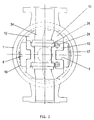
- Fig. 2 shows a horizontal section through the valve shown in fig. 1,
- Fig. 3 shows a vertical section through the valve as in fig. 1, but with the valve in closed position,
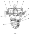
- Fig. 4 shows a vertical section through upper part and components attached to this, after they have been lifted out of the valve chamber in connection with a maintenance operation,
- Fig. 5 shows a horizontal outline of upper part and associated components which are shown in fig. 4,
- Fig. 6 shows a horizontal outline of the valve housing and lower part after the upper part has been lifted out,
- Fig. 7 shows a horizontal section through the valve housing and lower part which keeps the valve closed.
- The constructive design of the valve will be described in detail with reference to the figures 1-3. The valve comprises a
valve housing 1 with acover 2 which encompasses the upper parts of the valve. The cover is secured to the valve housing by means oflocking segments 38. The valve housing comprises further aninlet flange 3 and anoutlet flange 4 which connect to a not shown pipeline in a known manner. A duct for the fluid flow extends through the valve. In a practical embodiment there are supportingribs 37 arranged on the lower side of thevalve housing 1. On the upper side of thevalve housing 1, aninternal bonnet 24 is placed between thevalve housing 1 and thecover 2. - The rotatable component of the valve includes a U-shaped
lower part 6 which by way of ajournal 7 arranged on lower side is pivotally mounted in abearing 8 arranged in lower part of thevalve housing 1. Anupper part 10 is designed to be supportably placed against the internal portion of thelower part 6. In order to achieve a firm and stable support between upper and lower part,lower part 6 comprises arig 5, which engages with a groove 9 (fig. 5) inupper part 10. -
Upper part 10 comprises a through-going passage 34. In the area of respectively the passage's 34 inlet and outlet, theupper part 10 is provided withsealing elements upper part 10. The sealing elements compriseconical sealing surfaces valve seats valve housing 1.Lower part 6 comprises correspondingly designedspherical sealing surfaces sealing surfaces turn shaft 25 is pivotally mounted in a check bearing 23 in theinternal bonnet 24. The valve's rotatable member can rotate from an open position as shown in fig. 1, where the upper part's sealing faces bear against thevalve seats valve seats - For rotation of the rotating member, a
hydraulic actuator 21 which acts on aturn shaft 22 is arranged. Theturn shaft 22 is rigidly connected with the rotating member'sturn shaft 25. The upper portion of theturn shaft 22 comprises splines which engage with thehydraulic actuator 21. -
Upper part 10 is designed to be able to receive various types of controlling or metering instruments. The object of such equipment can be: - regulation of flow velocity
- recording of flow velocity
- measuring of temperature
- measuring of pressure
- volumetric metering of fluid flow
- For a person skilled in the art it is evident that other equipment, for example metering or monitoring equipment, can also easily be accommodated in
upper part 10. - With reference to the figures 4-7, a closer description of the method for maintenance of the valve's vital parts and of equipment placed in
upper part 10 will be provided. - The first step will be to close the valve by 90o rotation of the rotating member so that the
spherical sealing surfaces valve seats valve housing 1. The valve will now be closed at both the upstream and downstream ends. - The next step will be to equalize the pressure in the valve room with the ambient pressure before the
cover 2 of thevalve housing 1 is dismantled in that thelocking segments 38 are released.Upper part 10 and associated equipment can now be lifted out of thevalve housing 1 and be inspected/repaired. - In a preferred embodiment, particularly when used in an underwater pipeline,
upper part 10 and other components which are to undergo maintenance are attached to the underside of thecover 2. All components can now be lifted up to the surface via ahook 20 on the overside of the cover. The figures 4 and 5 show the unit which is lifted to the surface for maintenance, while the figures 6 and 7 show valve housing and lower part which remain where they are. - The
lower part 6 of the valve can preferably include an automatic locking mechanism which keeps it in a locked position whenupper part 10 is lifted up (not shown). - When the upper part with equipment is mounted after overhauling, or possibly when a new corresponding unit is mounted, the
groove 9 must enter above therib 5. The unit will halt in lower position in that a bearingedge 31 on the overhauled unit encounters thesupport 32 of the lower part. Bearing surfaces 33 on upper part will fasten the upper part for sideways position in relation to lower part. Before thecover 2 is fastened in a known way and the valve is rotated into open position, the valve room should be flushed.
Claims (8)
- Valve-apparatus, in particular a rotatable valve comprising an upper part (10)and a lower part (6) which are arranged in a valve housing (1) and demountably attached to each other, characterized in that lower part (6) is mainly U-formed with sealing faces (17, 18) arranged on the external side faces, which sealing faces, in the case of closed valve, bear against at least one valve seat on the valve housing's inlet and/or outlet end, and upper part's (10) external surface is designed for totally or partly supporting bearing against lower part's (6) internal surface and comprising a passage (34) intended for the accommodation of equipment, for example controlling or metering instruments in that upper part (10), in the case of closed valve, can be lifted out of the valve housing (1) for maintenance.
- Apparatus according to claim 1, characterized in that upper part's (10) sealing faces (13,14) in the valve's open position bear against the valve housing's (1) seats to form a closed fluid flow passage (34).
- Apparatus according to claim 1, characterized by the lower part (6) comprising a journal (7) arranged on the underside which is pivotally supported in a bearing (8).
- Apparatus according to claim 1, characterized in that upper part's (10) sealing surfaces comprise sealing members (11, 12), with conically shaped sealing surfaces (13, 14) for engagement with correspondingly designed valve seats (15, 16) at the inlet and outlet of the passage (34).
- Apparatus according to claim 1, characterized by the lower part (6) comprising a rib (5) which fits into a groove (9) on upper part (10) in order to keep the parts (6, 10) in a fixed position in relation to each other.
- Apparatus according to claim 1, characterized in that the revolvable member can be turned from open to closed position and vice versa via a rigidly connected turn shaft (22) which is pivotally mounted in a check bearing (23) in an internal bonnet (24) and comprises, in the upper free end, splines (25) which engage with a hydraulic actuator (21).
- Apparatus according to claim 1, characterized in that one or more controlling devices (26) are arranged in the passage of the upper part (10) for regulation of the fluid flow, each of which comprise rotatable discs (27) which can be displaced radially in relation to each other by means of a worm gear (28) which engages with a gear rim on at least one of the discs (26) of the valve.
- Apparatus according to claim 6, characterized in that the worm gear (28) is driven by a motor (30) placed in a bore (29) in upper part (10).
Applications Claiming Priority (2)
| Application Number | Priority Date | Filing Date | Title |
|---|---|---|---|
| NO890570A NO166200C (en) | 1989-02-10 | 1989-02-10 | DEVICE VALVE DEVICE. |
| NO890570 | 1989-02-10 |
Publications (2)
| Publication Number | Publication Date |
|---|---|
| EP0465473A1 EP0465473A1 (en) | 1992-01-15 |
| EP0465473B1 true EP0465473B1 (en) | 1994-01-05 |
Family
ID=19891742
Family Applications (1)
| Application Number | Title | Priority Date | Filing Date |
|---|---|---|---|
| EP90903229A Expired - Lifetime EP0465473B1 (en) | 1989-02-10 | 1990-02-07 | Valve |
Country Status (11)
| Country | Link |
|---|---|
| US (1) | US5224829A (en) |
| EP (1) | EP0465473B1 (en) |
| AT (1) | ATE99782T1 (en) |
| AU (1) | AU626131B2 (en) |
| BR (1) | BR9007102A (en) |
| CA (1) | CA2046322A1 (en) |
| DE (1) | DE69005817T2 (en) |
| DK (1) | DK0465473T3 (en) |
| FI (1) | FI94460C (en) |
| NO (1) | NO166200C (en) |
| WO (1) | WO1990009538A1 (en) |
Families Citing this family (8)
| Publication number | Priority date | Publication date | Assignee | Title |
|---|---|---|---|---|
| US5531244A (en) * | 1995-07-25 | 1996-07-02 | Conval, Inc. | Hemispherical ball valve |
| US5799928A (en) * | 1997-03-03 | 1998-09-01 | Conval Inc. | Ball valve with improved valve seat and bonnet assembly |
| US20030037817A1 (en) * | 2001-08-21 | 2003-02-27 | Fmc Technologies, Inc | High-speed water jet blocker |
| BRPI0419084B1 (en) * | 2004-10-12 | 2015-05-26 | Cameron Int Corp | Locking device |
| CN108302215B (en) * | 2018-04-08 | 2018-12-28 | 江苏圣泰阀门有限公司 | Ultralow temperature plug valve |
| CN112145719A (en) * | 2019-09-04 | 2020-12-29 | 吴紫阳 | Use control method of segmented flow blocking type pipeline self-sealing valve |
| AU2021228453B2 (en) * | 2020-02-25 | 2026-01-22 | Kitz Corporation | Valve |
| CN116447346B (en) * | 2023-04-12 | 2023-12-19 | 江苏苏盐阀门机械有限公司 | High-end intelligent valve |
Family Cites Families (20)
| Publication number | Priority date | Publication date | Assignee | Title |
|---|---|---|---|---|
| US1029354A (en) * | 1911-04-15 | 1912-06-11 | Herman Forsman | Faucet. |
| US3630484A (en) * | 1970-03-03 | 1971-12-28 | Julian S Taylor | Restrictor valve |
| US3656501A (en) * | 1970-05-26 | 1972-04-18 | Fmc Corp | Valve-operator assembly with alignment and locking mechanism |
| US3707161A (en) * | 1970-09-23 | 1972-12-26 | Douglas W Crawford | Variable choke valve |
| US3658087A (en) * | 1971-02-08 | 1972-04-25 | Acf Ind Inc | Valve with integral closure and seat carrier unit |
| US3700003A (en) * | 1971-04-15 | 1972-10-24 | Russell G Smith | Valve with flow regulating means |
| US3860032A (en) * | 1972-10-27 | 1975-01-14 | Chemetron Corp | Ball valve with flow control |
| US4187872A (en) * | 1976-11-02 | 1980-02-12 | Tapco International, Inc. | Control valve assembly |
| US4304261A (en) * | 1979-12-10 | 1981-12-08 | Forester Buford G | Valve |
| FR2492496A1 (en) * | 1980-10-17 | 1982-04-23 | Commissariat Energie Atomique | VALVE WITH DIRECT PASSAGE AND ROTARY CONTROL |
| US4432387A (en) * | 1982-09-20 | 1984-02-21 | Sims Don G | Rotating disc gate valve |
| US4562860A (en) * | 1983-07-06 | 1986-01-07 | Wilmington Trust Company | Ball valve having easy maintenance features for extreme environments |
| GB8319853D0 (en) * | 1983-07-22 | 1983-08-24 | Forsac Valves | Ball valve for pipeline |
| US4687016A (en) * | 1985-10-02 | 1987-08-18 | Niigata Engineering Co., Ltd. | Emergency release valve apparatus |
| AU588002B2 (en) * | 1985-10-03 | 1989-09-07 | Den Norske Stats Oljeselskap A.S. | Subsea shutdown valve with maintenance isolation bypass |
| NO159553C (en) * | 1986-03-12 | 1989-01-11 | Norske Stats Oljeselskap | BALL VALVE. |
| FR2610691B1 (en) * | 1987-02-09 | 1989-03-10 | Commissariat Energie Atomique | REMOTE CONTROL VALVE |
| NO163505C (en) * | 1987-08-17 | 1990-06-06 | Norske Stats Oljeselskap | Apparatus for ball valve maintenance. |
| GB8817358D0 (en) * | 1988-07-21 | 1988-08-24 | Cooper Ind Inc | Clamp assemblies |
| US4901977A (en) * | 1989-06-02 | 1990-02-20 | Automatic Control Components, Inc. | Gear drive for a disk |
-
1989
- 1989-02-10 NO NO890570A patent/NO166200C/en not_active IP Right Cessation
-
1990
- 1990-02-07 DK DK90903229.4T patent/DK0465473T3/en active
- 1990-02-07 WO PCT/NO1990/000031 patent/WO1990009538A1/en not_active Ceased
- 1990-02-07 EP EP90903229A patent/EP0465473B1/en not_active Expired - Lifetime
- 1990-02-07 DE DE69005817T patent/DE69005817T2/en not_active Expired - Fee Related
- 1990-02-07 BR BR909007102A patent/BR9007102A/en not_active IP Right Cessation
- 1990-02-07 CA CA002046322A patent/CA2046322A1/en not_active Abandoned
- 1990-02-07 AU AU50804/90A patent/AU626131B2/en not_active Ceased
- 1990-02-07 AT AT90903229T patent/ATE99782T1/en not_active IP Right Cessation
- 1990-02-07 US US07/743,353 patent/US5224829A/en not_active Expired - Fee Related
-
1991
- 1991-08-09 FI FI913783A patent/FI94460C/en active
Also Published As
| Publication number | Publication date |
|---|---|
| FI94460B (en) | 1995-05-31 |
| WO1990009538A1 (en) | 1990-08-23 |
| FI94460C (en) | 1995-09-11 |
| NO166200B (en) | 1991-03-04 |
| CA2046322A1 (en) | 1990-08-11 |
| NO890570L (en) | 1990-08-13 |
| EP0465473A1 (en) | 1992-01-15 |
| AU5080490A (en) | 1990-09-05 |
| ATE99782T1 (en) | 1994-01-15 |
| BR9007102A (en) | 1991-11-12 |
| DE69005817T2 (en) | 1994-06-16 |
| NO166200C (en) | 1991-06-12 |
| AU626131B2 (en) | 1992-07-23 |
| DE69005817D1 (en) | 1994-02-17 |
| NO890570D0 (en) | 1989-02-10 |
| US5224829A (en) | 1993-07-06 |
| DK0465473T3 (en) | 1994-03-21 |
| FI913783A0 (en) | 1991-08-09 |
Similar Documents
| Publication | Publication Date | Title |
|---|---|---|
| US6378842B1 (en) | V-ball control valve | |
| US20080308159A1 (en) | Top entry swing check valve | |
| AU626131B2 (en) | Valve | |
| EP0132989A2 (en) | Ball valve for pipeline | |
| Sotoodeh | A practical guide to piping and valves for the oil and gas industry | |
| US8834101B2 (en) | Mechanical seal for large pumps | |
| US7357145B2 (en) | High-pressure, hemi-wedge cartridge valve | |
| CA1191422A (en) | Check valve assembly for use in backflow preventers or the like | |
| JPH06100290B2 (en) | Undersea pipeline valve | |
| CA2797112C (en) | Mechanical seal for large pumps | |
| US8019038B2 (en) | Steam generator nozzle dam and method for installing and removing steam generator nozzle dam | |
| US9464726B2 (en) | Shut-off device for pipelines | |
| EP2661571B1 (en) | Check valve for a pipe section | |
| JPS62241533A (en) | Mixer driver | |
| US4921003A (en) | Shut-down valve | |
| US10480657B1 (en) | Mechanical pump seal | |
| US5030046A (en) | Valve seal ring seating machine | |
| EP1862712B1 (en) | Mixing valve and mixing device | |
| EP0159799B1 (en) | Ball valve | |
| WO1990012974A1 (en) | Compact multi-stage pressure reducing valve | |
| Hariram | Evaluation of valves for Cresap testing | |
| Kelly | Isolation Needle Valve For Rov (Remote Operated Vehicle) Operation | |
| Equipment | Navigation Bar | |
| NWAOHA et al. | ALI AHAMMAD SHOUKAT CHOUDHURY |
Legal Events
| Date | Code | Title | Description |
|---|---|---|---|
| PUAI | Public reference made under article 153(3) epc to a published international application that has entered the european phase |
Free format text: ORIGINAL CODE: 0009012 |
|
| 17P | Request for examination filed |
Effective date: 19910809 |
|
| AK | Designated contracting states |
Kind code of ref document: A1 Designated state(s): AT BE DE DK FR GB IT LU NL SE |
|
| 17Q | First examination report despatched |
Effective date: 19930204 |
|
| GRAA | (expected) grant |
Free format text: ORIGINAL CODE: 0009210 |
|
| ITF | It: translation for a ep patent filed | ||
| AK | Designated contracting states |
Kind code of ref document: B1 Designated state(s): AT BE DE DK FR GB IT LU NL SE |
|
| REF | Corresponds to: |
Ref document number: 99782 Country of ref document: AT Date of ref document: 19940115 Kind code of ref document: T |
|
| REF | Corresponds to: |
Ref document number: 69005817 Country of ref document: DE Date of ref document: 19940217 |
|
| REG | Reference to a national code |
Ref country code: DK Ref legal event code: T3 |
|
| ET | Fr: translation filed | ||
| EPTA | Lu: last paid annual fee | ||
| PLBE | No opposition filed within time limit |
Free format text: ORIGINAL CODE: 0009261 |
|
| STAA | Information on the status of an ep patent application or granted ep patent |
Free format text: STATUS: NO OPPOSITION FILED WITHIN TIME LIMIT |
|
| 26N | No opposition filed | ||
| EAL | Se: european patent in force in sweden |
Ref document number: 90903229.4 |
|
| REG | Reference to a national code |
Ref country code: GB Ref legal event code: IF02 |
|
| PGFP | Annual fee paid to national office [announced via postgrant information from national office to epo] |
Ref country code: SE Payment date: 20020206 Year of fee payment: 13 Ref country code: GB Payment date: 20020206 Year of fee payment: 13 |
|
| PGFP | Annual fee paid to national office [announced via postgrant information from national office to epo] |
Ref country code: FR Payment date: 20020212 Year of fee payment: 13 |
|
| PGFP | Annual fee paid to national office [announced via postgrant information from national office to epo] |
Ref country code: LU Payment date: 20020213 Year of fee payment: 13 Ref country code: DK Payment date: 20020213 Year of fee payment: 13 Ref country code: AT Payment date: 20020213 Year of fee payment: 13 |
|
| PGFP | Annual fee paid to national office [announced via postgrant information from national office to epo] |
Ref country code: DE Payment date: 20020227 Year of fee payment: 13 |
|
| PGFP | Annual fee paid to national office [announced via postgrant information from national office to epo] |
Ref country code: NL Payment date: 20020228 Year of fee payment: 13 |
|
| PGFP | Annual fee paid to national office [announced via postgrant information from national office to epo] |
Ref country code: BE Payment date: 20020418 Year of fee payment: 13 |
|
| PG25 | Lapsed in a contracting state [announced via postgrant information from national office to epo] |
Ref country code: LU Free format text: LAPSE BECAUSE OF NON-PAYMENT OF DUE FEES Effective date: 20030207 Ref country code: GB Free format text: LAPSE BECAUSE OF NON-PAYMENT OF DUE FEES Effective date: 20030207 Ref country code: AT Free format text: LAPSE BECAUSE OF NON-PAYMENT OF DUE FEES Effective date: 20030207 |
|
| PG25 | Lapsed in a contracting state [announced via postgrant information from national office to epo] |
Ref country code: SE Free format text: LAPSE BECAUSE OF NON-PAYMENT OF DUE FEES Effective date: 20030208 |
|
| PG25 | Lapsed in a contracting state [announced via postgrant information from national office to epo] |
Ref country code: DK Free format text: LAPSE BECAUSE OF NON-PAYMENT OF DUE FEES Effective date: 20030228 Ref country code: BE Free format text: LAPSE BECAUSE OF NON-PAYMENT OF DUE FEES Effective date: 20030228 |
|
| PG25 | Lapsed in a contracting state [announced via postgrant information from national office to epo] |
Ref country code: NL Free format text: LAPSE BECAUSE OF NON-PAYMENT OF DUE FEES Effective date: 20030901 |
|
| PG25 | Lapsed in a contracting state [announced via postgrant information from national office to epo] |
Ref country code: DE Free format text: LAPSE BECAUSE OF NON-PAYMENT OF DUE FEES Effective date: 20030902 |
|
| GBPC | Gb: european patent ceased through non-payment of renewal fee | ||
| REG | Reference to a national code |
Ref country code: DK Ref legal event code: EBP |
|
| EUG | Se: european patent has lapsed | ||
| PG25 | Lapsed in a contracting state [announced via postgrant information from national office to epo] |
Ref country code: FR Free format text: LAPSE BECAUSE OF NON-PAYMENT OF DUE FEES Effective date: 20031031 |
|
| NLV4 | Nl: lapsed or anulled due to non-payment of the annual fee |
Effective date: 20030901 |
|
| REG | Reference to a national code |
Ref country code: FR Ref legal event code: ST |
|
| PG25 | Lapsed in a contracting state [announced via postgrant information from national office to epo] |
Ref country code: IT Free format text: LAPSE BECAUSE OF NON-PAYMENT OF DUE FEES;WARNING: LAPSES OF ITALIAN PATENTS WITH EFFECTIVE DATE BEFORE 2007 MAY HAVE OCCURRED AT ANY TIME BEFORE 2007. THE CORRECT EFFECTIVE DATE MAY BE DIFFERENT FROM THE ONE RECORDED. Effective date: 20050207 |