EP0465383B1 - Künstliche Herzklappe - Google Patents
Künstliche Herzklappe Download PDFInfo
- Publication number
- EP0465383B1 EP0465383B1 EP19910420208 EP91420208A EP0465383B1 EP 0465383 B1 EP0465383 B1 EP 0465383B1 EP 19910420208 EP19910420208 EP 19910420208 EP 91420208 A EP91420208 A EP 91420208A EP 0465383 B1 EP0465383 B1 EP 0465383B1
- Authority
- EP
- European Patent Office
- Prior art keywords
- ring
- wings
- valve
- fins
- plane
- Prior art date
- Legal status (The legal status is an assumption and is not a legal conclusion. Google has not performed a legal analysis and makes no representation as to the accuracy of the status listed.)
- Expired - Lifetime
Links
Images

Classifications
-
- A—HUMAN NECESSITIES
- A61—MEDICAL OR VETERINARY SCIENCE; HYGIENE
- A61F—FILTERS IMPLANTABLE INTO BLOOD VESSELS; PROSTHESES; DEVICES PROVIDING PATENCY TO, OR PREVENTING COLLAPSING OF, TUBULAR STRUCTURES OF THE BODY, e.g. STENTS; ORTHOPAEDIC, NURSING OR CONTRACEPTIVE DEVICES; FOMENTATION; TREATMENT OR PROTECTION OF EYES OR EARS; BANDAGES, DRESSINGS OR ABSORBENT PADS; FIRST-AID KITS
- A61F2/00—Filters implantable into blood vessels; Prostheses, i.e. artificial substitutes or replacements for parts of the body; Appliances for connecting them with the body; Devices providing patency to, or preventing collapsing of, tubular structures of the body, e.g. stents
- A61F2/02—Prostheses implantable into the body
- A61F2/24—Heart valves ; Vascular valves, e.g. venous valves; Heart implants, e.g. passive devices for improving the function of the native valve or the heart muscle; Transmyocardial revascularisation [TMR] devices; Valves implantable in the body
- A61F2/2409—Support rings therefor, e.g. for connecting valves to tissue
-
- A—HUMAN NECESSITIES
- A61—MEDICAL OR VETERINARY SCIENCE; HYGIENE
- A61F—FILTERS IMPLANTABLE INTO BLOOD VESSELS; PROSTHESES; DEVICES PROVIDING PATENCY TO, OR PREVENTING COLLAPSING OF, TUBULAR STRUCTURES OF THE BODY, e.g. STENTS; ORTHOPAEDIC, NURSING OR CONTRACEPTIVE DEVICES; FOMENTATION; TREATMENT OR PROTECTION OF EYES OR EARS; BANDAGES, DRESSINGS OR ABSORBENT PADS; FIRST-AID KITS
- A61F2/00—Filters implantable into blood vessels; Prostheses, i.e. artificial substitutes or replacements for parts of the body; Appliances for connecting them with the body; Devices providing patency to, or preventing collapsing of, tubular structures of the body, e.g. stents
- A61F2/02—Prostheses implantable into the body
- A61F2/24—Heart valves ; Vascular valves, e.g. venous valves; Heart implants, e.g. passive devices for improving the function of the native valve or the heart muscle; Transmyocardial revascularisation [TMR] devices; Valves implantable in the body
- A61F2/2403—Heart valves ; Vascular valves, e.g. venous valves; Heart implants, e.g. passive devices for improving the function of the native valve or the heart muscle; Transmyocardial revascularisation [TMR] devices; Valves implantable in the body with pivoting rigid closure members
-
- Y—GENERAL TAGGING OF NEW TECHNOLOGICAL DEVELOPMENTS; GENERAL TAGGING OF CROSS-SECTIONAL TECHNOLOGIES SPANNING OVER SEVERAL SECTIONS OF THE IPC; TECHNICAL SUBJECTS COVERED BY FORMER USPC CROSS-REFERENCE ART COLLECTIONS [XRACs] AND DIGESTS
- Y10—TECHNICAL SUBJECTS COVERED BY FORMER USPC
- Y10T—TECHNICAL SUBJECTS COVERED BY FORMER US CLASSIFICATION
- Y10T137/00—Fluid handling
- Y10T137/7722—Line condition change responsive valves
- Y10T137/7837—Direct response valves [i.e., check valve type]
- Y10T137/7898—Pivoted valves
Definitions
- an anti-coagulant treatment administered orally is generally used.
- the purpose of this treatment is to limit the formation of clots at the valve mechanism.
- Valves are known, for example, the mechanism of which essentially comprises a ball with free movement in a metal cage having hoops secured to a metal ring.
- the existence of the ball in the middle of the blood flow may be responsible for an essentially lateral flow, so that the hemodynamic performance is not satisfactory.
- a tilting disc valve has been proposed by creating a lateral flow and the existence of a main area and a secondary area. It appeared however that this secondary area is responsible for stasis thereby causing thrombosis phenomena even in the case of anti-coagulant treatment.
- the valve does not have three equivalent areas.
- the two lateral areas each represent approximately 40 percent, while the central area represents only 20 percent. It therefore appears that the central area is used less than the lateral areas, so that the phenomena of stasis at this level, with insufficient blood scanning, can generate a phenomenon of thrombosis requiring anticoagulant treatment.
- valves with curved fins are also known which, unlike those described above, have three equivalent areas in the open position of the fins. Clinical trials have shown that the adoption of three equivalent areas significantly limits the phenomena of valve thrombosis. On the other hand, if one can consider that the problem of thrombogenicity is solved, it is not the same with regard to the problem of hemodynamics. Indeed, the opening of the fins is limited to about 76 degrees thereby generating, for the lateral areas, oblique waves. Another drawback also appears in the technological design as such of the valve, so that in the open position, the fins are very outside the ring which can cause, in particular in the mitral position, incidents of blockage of said fins by underlying ventricular structures.
- a first drawback is found at the articulation of the fins in the ring which does not delimit, between the ends of the fins, a completely smooth surface but profiled indentations capable of disturbing the central laminar flow.
- the fins are relatively thick, so that their elasticity is not sufficient to absorb the kinetic energy stored by the speed of the blood flow.
- the invention is therefore set to remedy these drawbacks and to solve the problem of designing an artificial heart valve whose characteristics are determined to solve both the problem of hemodynamics and that of thrombogenicity, as well that the significant problem of noise when closing the fins.
- a heart valve of the type defined in Claim 1 has been designed.
- valve has a minimum thrombogenicity possibly authorizing, in the post-operative period, a low regimen of anticoagulation due to the reduction in the areas of stasis, taking into account the reduction of the transprosthetic gradient, the existence of an axial and laminar flow also distributed at the level of the three equivalent areas, and perfectly washing the two faces of the fins.
- the articulation of the latter is effected by male hemispherical parts formed in overflow of the profile of each fin and capable of cooperating with complementary hemispherical cavities formed in the two ears of the ring.
- this design of the articulation of the fins makes it possible to leave between the ends of said fins a completely free space free of any asperities in hollow or relief allowing consequently a flow of the central flow under optimum conditions .
- the hemispherical male parts can be in a trifoliate form comprising three recesses offset by 60 degrees.
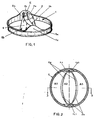
- the artificial valve comprises a ring (1) inside which are hinged two identical fins (2).
- the ring (1) has any external arrangement allowing, in a known manner, the insertion of a collar of tissue to constitute the suture ring as such.
- these arrangements are constituted by a groove (1a).
- valve is intended both for replacing the mitral valve and for replacing the aortic valve without any other modification than that of the suture ring, the shape of which is different depending on the position envisaged: aortic or mitral.
- the ring (1) has internal arrangements capable of ensuring the articulation of the fins (2) in a maximum open position to delimit, in combination with the profile of the fins, three equivalent areas (A1, A2, A3) allowing central, axial and laminar flow.
- the internal arrangements of the ring allow, in the closed position of the fins (2), their integration inside the ring.
- the internal arrangements of the ring (1) are constituted by two diametrically opposite parts (1b and 1c) formed directly overhanging one of the faces of the ring by constituting shoulders or ears.
- Each of the parts (1b, 1c) appears on the side of the intake face of the valve.
- the two protruding parts (1b, 1c) receiving the articulation mechanism of the fins (2) and constituting shoulders or ears, ensure the offset of the mechanism so that the fins (2) in the open position do not exceed the plane of the 'ring only of a reduced value varying according to their size.
- each of the parts (1b, 1c) constitutes, over the entire width of the ring, a flat internal surface having raised means (1b1, 1c1) shaped to ensure the angular locking of the fins according to a angle of at least 85 degrees.
- these means (1b1, 1c1) each consist of a boss formed in overflow from the internal flat face of each of the parts (1b, 1c) opposite the shoulder receiving the articulation mechanism of the fins. .
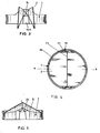
- the lateral edges of each of the bosses (1b1, 1c1) are inclined at an appropriate angle to allow, as indicated, the blocking in the open position of each of the fins at least 85 degrees. In addition, this angle is determined so that in the open position of the fins, the latter tend to converge towards each of the shoulders (1b, 1c) receiving the articulation mechanism ( Figure 3).
- each of the fins has a profile in curved section so that in the open position, the central orifice delimited by the fins has a central area (A2) equivalent or greater than each of the two lateral areas (A1 and A3).
- This open position limited to at least 85 degrees ensures axial and laminar flow.
- each of the fins (2) are profiled according to a curvature capable of marrying the internal radius of the ring.
- the edges (2a) have an appropriate and determined curvature to ensure contiguous contact between the two fins. In the closed position, the fins form an obtuse angle.
- each of the fins (2) is effected by male hemispherical parts (2c) formed at each end directly in the extension of the edges of each fin.
- Each of these hemispherical parts (2c) is able to cooperate with complementary hemispherical cavities (1d) formed at the flat section of each shoulder. These cavities (1d) are only separated by a few millimeters.
- the hemispherical male part integral with the fin may constitute either a total hemisphere, or a trifoliated hemisphere notched with three recesses angularly offset at an angle of about 60 degrees. Such arrangements make it possible to provide each of the articulation movements with a sweep of the concave surface aimed at limiting the formation of thromboses at the level of the articulation.
- the ring (1) and the fins (2) are made of titanium or titanium alloy covered with an amorphous and isotropic carbon film.
- the high resistance of this titanium alloy makes it possible to have fins and a ring of very reduced thickness, while considerably increasing the mechanical characteristics of the valve.
- the titanium covering film in the form of a thin layer of amorphous carbon constitutes a continuous structure with a completely smooth non-porous appearance and with less surface tension. This results in very low wettability ensuring blood flow without slowing down and thus giving it very good hemodynamic performance.
Landscapes
- Health & Medical Sciences (AREA)
- Cardiology (AREA)
- Engineering & Computer Science (AREA)
- Biomedical Technology (AREA)
- Life Sciences & Earth Sciences (AREA)
- Transplantation (AREA)
- Heart & Thoracic Surgery (AREA)
- Vascular Medicine (AREA)
- Oral & Maxillofacial Surgery (AREA)
- Animal Behavior & Ethology (AREA)
- General Health & Medical Sciences (AREA)
- Public Health (AREA)
- Veterinary Medicine (AREA)
- Prostheses (AREA)
- External Artificial Organs (AREA)
- Materials For Medical Uses (AREA)
Claims (3)
- Künstliche Herzklappe mit einem Ring (1), innerhalb dessen zwei gebogene Flügel (2) gelenkig gelagert sind, die sich mindestens um 85° öffnen und in geöffneter Stellung in der Ringebene (1) drei hydraulisch gleichwertige Flächen (A1) (A2) (A3) umschreiben, gekennzeichnet durch die Kombination der folgenden Vorrichtungen:- die Flügel (2) sind mit einem Film aus amorphem und isotropem Kohlenstoff überzogen, um eine hohe Elastizitätsgrenze sowie eine große Duktilität und Schlagzähigkeit zu erzielen, damit die besagten Flügeln (2) schmaler ausfallen können und ihnen eine kontrollierte Elastizität verliehen wird,- die Gelenkachsen (2c) der Flügel (2) sind oberhalb und außerhalb der mittleren Ringebene (1) angeordnet, um das Klappenprofil zu verringern, wenn sich die Flügel (2) in geöffneter Stellung befinden,- die Enden der Gelenkachsen (2c) der Flügel (2) weisen Vorkehrungen auf, die geeignet sind, mit ergänzenden, in der Materialdicke ausgebildeten Vorkehrungen (1d) eines oberhalb und außerhalb der Ringebene versetzten Teils zusammenzuwirken, wobei diese Vorkehrungen (1d) geeignet sind, eine translationsfreie Drehbewegung zu ermöglichen,- die Außenränder (2b) der Flügel (2) besitzen das Profil eines teilweise elliptischen Bogens, um das Innenprofil des Ringes (1) oberhalb der mittleren Ebene des Ringes bei geschlossener Flügelstellung vollkommen nachzubilden,- die Profile (2a) (2b) der Innen- und Außenränder der Flügel (2) sind so beschaffen, um in der Ringebene zusammen mit dem Krümmungsradius des mittleren Teils der Flügel drei hydraulisch gleichwertige Flächen (A1) (A2) (A3) zu umschreiben, das Profil der Flügel (2) im Bereich der Gelenkvorkehrungen (2c) (1d) freizusetzen und ein besseres Eindringen in den Blutstrom zu gewährleisten, und- der oberhalb und außerhalb der Ringebene (1) versetzte Teil, der geeignet ist, die Gelenkachsen (2c) der Flügel (2) aufzunehmen, wird durch zwei diametral entgegengesetzte Vorsprünge (1b) (1c) gebildet, die sich von der Ringbasis aus bis zur Einlaßseite des Blutstroms erstrecken, wobei jeder Vorsprung eine zylindrische Außenfläche und eine abgeflachte Innenfläche aufweist und Reliefs (1b1) (1c1) besitzt, die so ausgebildet sind, um in einer Öffnungsposition von mindestens 85° die Blockierung der Flügel (2) zu gewährleisten.
- Klappe nach Anspruch 1, dadurch gekennzeichnet, daß die Vorkehrungen der Gelenkachsen (2c) aus halbkugelförmigen männlichen Teilen bestehen, die geeignet sind, mit ergänzenden halbkugelförmigen Vertiefungen (1d) im Bereich des abgeflachten Innenabschnitts des jeweiligen Vorsprungs (1b) (1c) zusammenzuwirken.
- Klappe nach Anspruch 2, dadurch gekennzeichnet, daß die halbkugelförmigen männlichen Teile (2c) dreiblättrig sind und winkelig versetzte Aussparungen - vor allem drei um 60 Grad versetzte Aussparungen - aufweisen können.
Applications Claiming Priority (2)
| Application Number | Priority Date | Filing Date | Title |
|---|---|---|---|
| FR9008191 | 1990-06-22 | ||
| FR9008191A FR2663533B1 (fr) | 1990-06-22 | 1990-06-22 | Valve cardiaque artificielle. |
Publications (2)
| Publication Number | Publication Date |
|---|---|
| EP0465383A1 EP0465383A1 (de) | 1992-01-08 |
| EP0465383B1 true EP0465383B1 (de) | 1997-09-10 |
Family
ID=9398133
Family Applications (1)
| Application Number | Title | Priority Date | Filing Date |
|---|---|---|---|
| EP19910420208 Expired - Lifetime EP0465383B1 (de) | 1990-06-22 | 1991-06-21 | Künstliche Herzklappe |
Country Status (5)
| Country | Link |
|---|---|
| US (1) | US5397347A (de) |
| EP (1) | EP0465383B1 (de) |
| AT (1) | ATE157858T1 (de) |
| DE (1) | DE69127593T2 (de) |
| FR (1) | FR2663533B1 (de) |
Families Citing this family (31)
| Publication number | Priority date | Publication date | Assignee | Title |
|---|---|---|---|---|
| US5628792A (en) * | 1992-03-13 | 1997-05-13 | Jcl Technic Ab | Cardiac valve with recessed valve flap hinges |
| FR2694689B1 (fr) * | 1992-08-11 | 1994-09-23 | Implants Instr Ch Fab | Valve cardiaque artificielle. |
| US5554186A (en) * | 1994-12-22 | 1996-09-10 | Baxter International Inc. | Bileaflet mechanical heart valve having cropped slot pivot configuration and method for preventing blood stagnation therein |
| US6296663B1 (en) | 1995-03-29 | 2001-10-02 | Medical Cv, Inc. | Bileaflet heart valve having open channel and swivel pivots |
| US5814099A (en) * | 1996-08-12 | 1998-09-29 | Bicer; Demetrio | Central opening curved bileaflet heart valve prosthesis |
| USD430935S (en) * | 1997-11-05 | 2000-09-12 | Yanqi Yang | Cardiac valve |
| JP4080690B2 (ja) | 1997-12-05 | 2008-04-23 | セント ジュード メディカル インコーポレイテッド | 二葉弁式人工心臓弁 |
| DE19755738A1 (de) * | 1997-12-16 | 1999-07-15 | Adiam Medizintechnik Gmbh & Co | Verfahren zur trennenden und/oder abtragenden Bearbeitung von vorgefertigten Kunststoff-Folien |
| AU2583200A (en) | 1998-12-28 | 2000-07-31 | Andrei Vasilievich Agafonov | Heart valve prosthesis |
| US6395025B1 (en) | 1998-12-31 | 2002-05-28 | St. Jude Medical, Inc. | Mechanical heart valve prosthesis |
| US6730122B1 (en) | 2000-11-28 | 2004-05-04 | St. Jude Medical, Inc. | Prosthetic heart valve with increased lumen |
| US8220489B2 (en) | 2002-12-18 | 2012-07-17 | Vapor Technologies Inc. | Faucet with wear-resistant valve component |
| US7866342B2 (en) | 2002-12-18 | 2011-01-11 | Vapor Technologies, Inc. | Valve component for faucet |
| US7866343B2 (en) | 2002-12-18 | 2011-01-11 | Masco Corporation Of Indiana | Faucet |
| US8555921B2 (en) | 2002-12-18 | 2013-10-15 | Vapor Technologies Inc. | Faucet component with coating |
| EP1734903B2 (de) | 2004-03-11 | 2022-01-19 | Percutaneous Cardiovascular Solutions Pty Limited | Perkutane herzklappenprothese |
| DE102005053966A1 (de) * | 2005-11-11 | 2007-05-16 | Tricumed Medizintechnik Gmbh | Herzklappe |
| GB2440912B (en) * | 2006-08-14 | 2009-03-04 | Heartvalve Ltd | Surgical fastening device |
| WO2010057262A1 (en) | 2008-11-21 | 2010-05-27 | Percutaneous Cardiovascular Solutions Pty Limited | Heart valve prosthesis and method |
| US8845717B2 (en) | 2011-01-28 | 2014-09-30 | Middle Park Medical, Inc. | Coaptation enhancement implant, system, and method |
| US8888843B2 (en) | 2011-01-28 | 2014-11-18 | Middle Peak Medical, Inc. | Device, system, and method for transcatheter treatment of valve regurgitation |
| US9339636B1 (en) | 2012-09-06 | 2016-05-17 | Mubashir H Khan | Subcutaneous fluid pump |
| US10166098B2 (en) | 2013-10-25 | 2019-01-01 | Middle Peak Medical, Inc. | Systems and methods for transcatheter treatment of valve regurgitation |
| WO2015195823A1 (en) | 2014-06-18 | 2015-12-23 | Middle Peak Medical, Inc. | Mitral valve implants for the treatment of valvular regurgitation |
| JP6740140B2 (ja) | 2014-06-24 | 2020-08-12 | ポラレス・メディカル・インコーポレイテッド | インプラントを固定するためのシステムおよび方法 |
| US9592121B1 (en) | 2015-11-06 | 2017-03-14 | Middle Peak Medical, Inc. | Device, system, and method for transcatheter treatment of valvular regurgitation |
| US10478303B2 (en) | 2017-03-13 | 2019-11-19 | Polares Medical Inc. | Device, system, and method for transcatheter treatment of valvular regurgitation |
| US10653524B2 (en) | 2017-03-13 | 2020-05-19 | Polares Medical Inc. | Device, system, and method for transcatheter treatment of valvular regurgitation |
| WO2018169878A1 (en) | 2017-03-13 | 2018-09-20 | Middle Peak Medical, Inc. | Device, system, and method for transcatheter treatment of valvular regurgitation |
| US11464634B2 (en) | 2020-12-16 | 2022-10-11 | Polares Medical Inc. | Device, system, and method for transcatheter treatment of valvular regurgitation with secondary anchors |
| US11759321B2 (en) | 2021-06-25 | 2023-09-19 | Polares Medical Inc. | Device, system, and method for transcatheter treatment of valvular regurgitation |
Family Cites Families (8)
| Publication number | Priority date | Publication date | Assignee | Title |
|---|---|---|---|---|
| US3546711A (en) * | 1968-04-09 | 1970-12-15 | Gulf Energy & Environ Systems | Heart valve |
| US4276658A (en) * | 1977-11-02 | 1981-07-07 | St. Jude Medical, Inc. | Heart valve prosthesis |
| US4178639A (en) * | 1978-04-06 | 1979-12-18 | Carbomedics, Inc. | Two-leaflet heart valve |
| US4328592A (en) * | 1979-08-07 | 1982-05-11 | Hemex, Inc. | Heart valve prosthesis |
| US4443894A (en) * | 1982-04-12 | 1984-04-24 | Hemex, Inc. | Heart valve with dog-leg pivot |
| DK164255C (da) * | 1985-07-24 | 1992-10-26 | David M Mcqueen | Hjerteventilprotese |
| US4892540A (en) * | 1988-04-21 | 1990-01-09 | Sorin Biomedica S.P.A. | Two-leaflet prosthetic heart valve |
| US4863458A (en) * | 1988-12-14 | 1989-09-05 | Carbomedics Inc. | Heart valve prosthesis having configured leaflets and mounting ears |
-
1990
- 1990-06-22 FR FR9008191A patent/FR2663533B1/fr not_active Expired - Fee Related
-
1991
- 1991-06-21 AT AT91420208T patent/ATE157858T1/de not_active IP Right Cessation
- 1991-06-21 EP EP19910420208 patent/EP0465383B1/de not_active Expired - Lifetime
- 1991-06-21 DE DE1991627593 patent/DE69127593T2/de not_active Expired - Fee Related
-
1993
- 1993-05-03 US US08/057,211 patent/US5397347A/en not_active Expired - Fee Related
Also Published As
| Publication number | Publication date |
|---|---|
| EP0465383A1 (de) | 1992-01-08 |
| FR2663533B1 (fr) | 1997-10-24 |
| DE69127593T2 (de) | 1998-02-19 |
| US5397347A (en) | 1995-03-14 |
| DE69127593D1 (de) | 1997-10-16 |
| FR2663533A1 (fr) | 1991-12-27 |
| ATE157858T1 (de) | 1997-09-15 |
Similar Documents
| Publication | Publication Date | Title |
|---|---|---|
| EP0465383B1 (de) | Künstliche Herzklappe | |
| EP0220097B1 (de) | Herzklappenprothese | |
| EP0383676A1 (de) | Herzklappenprothese | |
| EP0121473B1 (de) | Herzklappenprothese mit wirksamem Schliesskörper | |
| EP0913134B1 (de) | Knieprothese | |
| FR1464971A (fr) | Clapet utilisable notamment en chirurgie | |
| EP2802292A1 (de) | Verankerungsvorrichtung für eine künstliche herzklappe | |
| FR2708458A1 (fr) | Anneau prothétique pour chirurgie cardiaque. | |
| EP0079844B1 (de) | Künstliche Herzklappe | |
| BE690790A (fr) | Valve unidirectionnelle | |
| FR2744909A1 (fr) | Systeme d'activation d'une valve cardiaque | |
| WO2000041652A1 (fr) | Valvule prothetique implantable par catheterisme, ou chirurgicalement | |
| FR2799952A1 (fr) | Implant intraoculaire | |
| CA2685802A1 (fr) | Valve cardiaque prothetique mecanique | |
| WO1999048442A1 (fr) | Lentille intraoculaire monobloc souple | |
| CH717037A1 (fr) | Valve cardiaque prothétique mécanique. | |
| EP0318351A1 (de) | Künstliche Herzklappe | |
| CH717036A1 (fr) | Valve cardiaque prothétique mécanique. | |
| EP1824422A2 (de) | Hüftgelenksprothese zur zementlosen fixierung | |
| FR2581535A1 (fr) | Lentille intra-oculaire de chambre anterieure | |
| CH717035A1 (fr) | Valve cardiaque prothétique mécanique. | |
| EP0594511B1 (de) | Herzklappenprothese | |
| FR3138297A1 (fr) | Prothèse valvulaire cardiaque mécanique. | |
| FR2462149A1 (fr) | Prothese de valvule cardiaque | |
| FR2548888A1 (fr) | Valve cardiaque artificielle |
Legal Events
| Date | Code | Title | Description |
|---|---|---|---|
| PUAI | Public reference made under article 153(3) epc to a published international application that has entered the european phase |
Free format text: ORIGINAL CODE: 0009012 |
|
| AK | Designated contracting states |
Kind code of ref document: A1 Designated state(s): AT BE CH DE DK ES FR GB GR IT LI LU NL SE |
|
| 17P | Request for examination filed |
Effective date: 19920707 |
|
| 17Q | First examination report despatched |
Effective date: 19931216 |
|
| GRAG | Despatch of communication of intention to grant |
Free format text: ORIGINAL CODE: EPIDOS AGRA |
|
| GRAH | Despatch of communication of intention to grant a patent |
Free format text: ORIGINAL CODE: EPIDOS IGRA |
|
| GRAH | Despatch of communication of intention to grant a patent |
Free format text: ORIGINAL CODE: EPIDOS IGRA |
|
| GRAA | (expected) grant |
Free format text: ORIGINAL CODE: 0009210 |
|
| AK | Designated contracting states |
Kind code of ref document: B1 Designated state(s): AT BE CH DE DK ES FR GB GR IT LI LU NL SE |
|
| PG25 | Lapsed in a contracting state [announced via postgrant information from national office to epo] |
Ref country code: NL Free format text: LAPSE BECAUSE OF FAILURE TO SUBMIT A TRANSLATION OF THE DESCRIPTION OR TO PAY THE FEE WITHIN THE PRESCRIBED TIME-LIMIT Effective date: 19970910 Ref country code: GR Free format text: LAPSE BECAUSE OF FAILURE TO SUBMIT A TRANSLATION OF THE DESCRIPTION OR TO PAY THE FEE WITHIN THE PRESCRIBED TIME-LIMIT Effective date: 19970910 Ref country code: ES Free format text: THE PATENT HAS BEEN ANNULLED BY A DECISION OF A NATIONAL AUTHORITY Effective date: 19970910 Ref country code: DK Free format text: LAPSE BECAUSE OF NON-PAYMENT OF DUE FEES Effective date: 19970910 Ref country code: AT Effective date: 19970910 |
|
| REF | Corresponds to: |
Ref document number: 157858 Country of ref document: AT Date of ref document: 19970915 Kind code of ref document: T |
|
| REG | Reference to a national code |
Ref country code: CH Ref legal event code: EP |
|
| GBT | Gb: translation of ep patent filed (gb section 77(6)(a)/1977) |
Effective date: 19970910 |
|
| REF | Corresponds to: |
Ref document number: 69127593 Country of ref document: DE Date of ref document: 19971016 |
|
| ITF | It: translation for a ep patent filed |
Owner name: ING. A. GIAMBROCONO & C. S.R.L. |
|
| PG25 | Lapsed in a contracting state [announced via postgrant information from national office to epo] |
Ref country code: SE Effective date: 19971210 |
|
| NLV1 | Nl: lapsed or annulled due to failure to fulfill the requirements of art. 29p and 29m of the patents act | ||
| PG25 | Lapsed in a contracting state [announced via postgrant information from national office to epo] |
Ref country code: LU Free format text: LAPSE BECAUSE OF NON-PAYMENT OF DUE FEES Effective date: 19980621 |
|
| PG25 | Lapsed in a contracting state [announced via postgrant information from national office to epo] |
Ref country code: LI Free format text: LAPSE BECAUSE OF NON-PAYMENT OF DUE FEES Effective date: 19980630 Ref country code: CH Free format text: LAPSE BECAUSE OF NON-PAYMENT OF DUE FEES Effective date: 19980630 Ref country code: BE Free format text: LAPSE BECAUSE OF NON-PAYMENT OF DUE FEES Effective date: 19980630 |
|
| PLBE | No opposition filed within time limit |
Free format text: ORIGINAL CODE: 0009261 |
|
| STAA | Information on the status of an ep patent application or granted ep patent |
Free format text: STATUS: NO OPPOSITION FILED WITHIN TIME LIMIT |
|
| 26N | No opposition filed | ||
| BERE | Be: lapsed |
Owner name: FABRIQUE D' IMPLANTS ET D' INSTRUMENTS CHIRURGICAU Effective date: 19980630 |
|
| REG | Reference to a national code |
Ref country code: CH Ref legal event code: PL |
|
| PG25 | Lapsed in a contracting state [announced via postgrant information from national office to epo] |
Ref country code: FR Free format text: LAPSE BECAUSE OF NON-PAYMENT OF DUE FEES Effective date: 19990226 |
|
| REG | Reference to a national code |
Ref country code: FR Ref legal event code: ST |
|
| PGFP | Annual fee paid to national office [announced via postgrant information from national office to epo] |
Ref country code: DE Payment date: 20010613 Year of fee payment: 11 |
|
| PGFP | Annual fee paid to national office [announced via postgrant information from national office to epo] |
Ref country code: GB Payment date: 20010615 Year of fee payment: 11 |
|
| REG | Reference to a national code |
Ref country code: GB Ref legal event code: IF02 |
|
| PG25 | Lapsed in a contracting state [announced via postgrant information from national office to epo] |
Ref country code: GB Free format text: LAPSE BECAUSE OF NON-PAYMENT OF DUE FEES Effective date: 20020621 |
|
| PG25 | Lapsed in a contracting state [announced via postgrant information from national office to epo] |
Ref country code: DE Free format text: LAPSE BECAUSE OF NON-PAYMENT OF DUE FEES Effective date: 20030101 |
|
| GBPC | Gb: european patent ceased through non-payment of renewal fee |
Effective date: 20020621 |
|
| PG25 | Lapsed in a contracting state [announced via postgrant information from national office to epo] |
Ref country code: IT Free format text: LAPSE BECAUSE OF NON-PAYMENT OF DUE FEES;WARNING: LAPSES OF ITALIAN PATENTS WITH EFFECTIVE DATE BEFORE 2007 MAY HAVE OCCURRED AT ANY TIME BEFORE 2007. THE CORRECT EFFECTIVE DATE MAY BE DIFFERENT FROM THE ONE RECORDED. Effective date: 20050621 |