EP0465276B1 - Method for determining oil and water saturation in earth formation surrounding a borehole - Google Patents
Method for determining oil and water saturation in earth formation surrounding a borehole Download PDFInfo
- Publication number
- EP0465276B1 EP0465276B1 EP91401189A EP91401189A EP0465276B1 EP 0465276 B1 EP0465276 B1 EP 0465276B1 EP 91401189 A EP91401189 A EP 91401189A EP 91401189 A EP91401189 A EP 91401189A EP 0465276 B1 EP0465276 B1 EP 0465276B1
- Authority
- EP
- European Patent Office
- Prior art keywords
- borehole
- formation
- carbon
- oxygen
- environmental conditions
- Prior art date
- Legal status (The legal status is an assumption and is not a legal conclusion. Google has not performed a legal analysis and makes no representation as to the accuracy of the status listed.)
- Expired - Lifetime
Links
- 230000015572 biosynthetic process Effects 0.000 title claims description 51
- 238000000034 method Methods 0.000 title claims description 44
- XLYOFNOQVPJJNP-UHFFFAOYSA-N water Substances O XLYOFNOQVPJJNP-UHFFFAOYSA-N 0.000 title claims description 30
- 229910052760 oxygen Inorganic materials 0.000 claims description 64
- 229910052799 carbon Inorganic materials 0.000 claims description 63
- OKTJSMMVPCPJKN-UHFFFAOYSA-N Carbon Chemical compound [C] OKTJSMMVPCPJKN-UHFFFAOYSA-N 0.000 claims description 53
- QVGXLLKOCUKJST-UHFFFAOYSA-N atomic oxygen Chemical compound [O] QVGXLLKOCUKJST-UHFFFAOYSA-N 0.000 claims description 44
- 239000001301 oxygen Substances 0.000 claims description 44
- 238000012886 linear function Methods 0.000 claims description 20
- 229930195733 hydrocarbon Natural products 0.000 claims description 18
- 150000002430 hydrocarbons Chemical class 0.000 claims description 18
- 230000007613 environmental effect Effects 0.000 claims description 15
- 239000004215 Carbon black (E152) Substances 0.000 claims description 12
- 238000006243 chemical reaction Methods 0.000 claims description 11
- 238000000084 gamma-ray spectrum Methods 0.000 claims description 5
- 230000001678 irradiating effect Effects 0.000 claims description 5
- 238000005755 formation reaction Methods 0.000 description 44
- 239000003921 oil Substances 0.000 description 28
- 238000001228 spectrum Methods 0.000 description 25
- 239000011159 matrix material Substances 0.000 description 23
- 238000005259 measurement Methods 0.000 description 19
- 239000012530 fluid Substances 0.000 description 18
- 230000005251 gamma ray Effects 0.000 description 9
- 230000008901 benefit Effects 0.000 description 6
- 239000011148 porous material Substances 0.000 description 6
- 238000004364 calculation method Methods 0.000 description 5
- 230000000875 corresponding effect Effects 0.000 description 5
- XEEYBQQBJWHFJM-UHFFFAOYSA-N Iron Chemical compound [Fe] XEEYBQQBJWHFJM-UHFFFAOYSA-N 0.000 description 4
- 239000000470 constituent Substances 0.000 description 4
- 230000008569 process Effects 0.000 description 4
- OYPRJOBELJOOCE-UHFFFAOYSA-N Calcium Chemical compound [Ca] OYPRJOBELJOOCE-UHFFFAOYSA-N 0.000 description 3
- XUIMIQQOPSSXEZ-UHFFFAOYSA-N Silicon Chemical compound [Si] XUIMIQQOPSSXEZ-UHFFFAOYSA-N 0.000 description 3
- 125000004429 atom Chemical group 0.000 description 3
- 229910052791 calcium Inorganic materials 0.000 description 3
- 239000011575 calcium Substances 0.000 description 3
- 239000007789 gas Substances 0.000 description 3
- 238000011545 laboratory measurement Methods 0.000 description 3
- 238000004519 manufacturing process Methods 0.000 description 3
- 125000004430 oxygen atom Chemical group O* 0.000 description 3
- 150000003839 salts Chemical class 0.000 description 3
- 229910052710 silicon Inorganic materials 0.000 description 3
- 239000010703 silicon Substances 0.000 description 3
- 230000003595 spectral effect Effects 0.000 description 3
- 238000004458 analytical method Methods 0.000 description 2
- VTYYLEPIZMXCLO-UHFFFAOYSA-L calcium carbonate Substances [Ca+2].[O-]C([O-])=O VTYYLEPIZMXCLO-UHFFFAOYSA-L 0.000 description 2
- 239000002131 composite material Substances 0.000 description 2
- 230000002596 correlated effect Effects 0.000 description 2
- 238000001514 detection method Methods 0.000 description 2
- 238000013213 extrapolation Methods 0.000 description 2
- JEGUKCSWCFPDGT-UHFFFAOYSA-N h2o hydrate Chemical compound O.O JEGUKCSWCFPDGT-UHFFFAOYSA-N 0.000 description 2
- 229910052742 iron Inorganic materials 0.000 description 2
- 239000007788 liquid Substances 0.000 description 2
- 235000019738 Limestone Nutrition 0.000 description 1
- 229910000831 Steel Inorganic materials 0.000 description 1
- 235000010216 calcium carbonate Nutrition 0.000 description 1
- 150000001721 carbon Chemical group 0.000 description 1
- 125000004432 carbon atom Chemical group C* 0.000 description 1
- 230000008859 change Effects 0.000 description 1
- 238000011109 contamination Methods 0.000 description 1
- 230000001276 controlling effect Effects 0.000 description 1
- 239000010459 dolomite Substances 0.000 description 1
- 229910000514 dolomite Inorganic materials 0.000 description 1
- 230000000694 effects Effects 0.000 description 1
- 238000005516 engineering process Methods 0.000 description 1
- 239000013505 freshwater Substances 0.000 description 1
- 230000006872 improvement Effects 0.000 description 1
- 238000002347 injection Methods 0.000 description 1
- 239000007924 injection Substances 0.000 description 1
- 230000003993 interaction Effects 0.000 description 1
- 238000011835 investigation Methods 0.000 description 1
- 239000006028 limestone Substances 0.000 description 1
- 230000005855 radiation Effects 0.000 description 1
- 239000011435 rock Substances 0.000 description 1
- 229920006395 saturated elastomer Polymers 0.000 description 1
- 239000010959 steel Substances 0.000 description 1
- 238000006467 substitution reaction Methods 0.000 description 1
Images

Classifications
-
- G—PHYSICS
- G01—MEASURING; TESTING
- G01V—GEOPHYSICS; GRAVITATIONAL MEASUREMENTS; DETECTING MASSES OR OBJECTS; TAGS
- G01V5/00—Prospecting or detecting by the use of nuclear radiation, e.g. of natural or induced radioactivity
- G01V5/04—Prospecting or detecting by the use of nuclear radiation, e.g. of natural or induced radioactivity specially adapted for well-logging
- G01V5/08—Prospecting or detecting by the use of nuclear radiation, e.g. of natural or induced radioactivity specially adapted for well-logging using primary nuclear radiation sources or X-rays
- G01V5/10—Prospecting or detecting by the use of nuclear radiation, e.g. of natural or induced radioactivity specially adapted for well-logging using primary nuclear radiation sources or X-rays using neutron sources
- G01V5/101—Prospecting or detecting by the use of nuclear radiation, e.g. of natural or induced radioactivity specially adapted for well-logging using primary nuclear radiation sources or X-rays using neutron sources and detecting the secondary Y-rays produced in the surrounding layers of the bore hole
Definitions
- This invention relates to nuclear well logging method for determining the nature of fluids in formations through which a borehole is formed as well as the nature of fluids in the borehole. More particularly, the invention relates to determining the hydrocarbon saturation (or its correlative, water saturation) of formations adjacent a borehole by nuclear radiation logging. Still more particularly, the invention relates to inelastic gamma ray spectrum logging of a formation with correction for gamma rays from borehole fluids.
- a major goal of well logging is to establish the fraction of pore space in the earth formation occupied by hydrocarbons.
- Three methods of doing so have been developed in the prior art.
- S o or "oil" saturation, will be used hereafter to refer not only to liquid hydrocarbons, but also to gas.
- Both the electrical resistivity and thermal neutron decay methods depend upon the presence of salts dissolved in the water and, for that reason, are less effective in fresh water than in salt water environments.
- the third known method is based on the fact that hydrocarbons contain carbon and water contains oxygen.
- a high energy neutron usually called “fast neutron”
- fast neutron When a high energy neutron, usually called “fast neutron”, is scattered inelastically from a carbon atom, a 4.4 MeV gamma ray is emitted.
- a fast neutron When a fast neutron is scattered from an oxygen atom, a 6.1 MeV gamma ray is emitted among others. Therefore, a logging apparatus which counts the number of 4.4 MeV gamma rays and the number of 6.1 MeV gamma rays and determines their ratio should be, under ideal conditions, able to provide a measure of the ratio of carbon to oxygen in the formation.
- Such measurements are known in the art as carbon/oxygen or simply, C/O measurements or C/O logs. Moreover, a calcium/silicon ratio can also be obtained. Comparison of these two ratios permits the user to distinguish carbon in calcium carbonates from that in hydrocarbons.
- the well bore may contain hydrocarbons (in the form of oil or gas) and water. Consequently, C/O measurements of the formation are contaminated or "corrupted" with gamma rays resulting from fast neutron interaction with carbon and oxygen atoms of fluids in the borehole.
- lithologies such as dolomite and limestone, contain carbon atoms. Such contamination of the inelastic gamma ray spectral data, and ultimately of the s o determination, may be eliminated if the porosity, lithology, borehole configuration and hydrocarbon content of the fluid in the well bore is known.
- Characteristics as a function of depth of a cased well such as porosity and lithology of the formation and the borehole configuration may be known. But C/O logging measurements of cased, producing wells have required that the well be "shut-in” so that the borehole fluid components may be known better. However, even with shut-in wells, the content of borehole fluid is not always known well enough.
- the C/O measurements are carried out by using a logging tool provided with a near and a far detector.
- the relative amounts of carbon and oxygen C n , O n as measured from the near detector, and the relative amounts of carbon and oxygen C f , O f , as measured from the far detector, are obtained.
- a least squares analysis is performed to determine C n , O n from the energy spectrum (counts versus energy) acquired from the near detector, using standard spectra for the near detector, C f and O f are determined from the energy spectrum as measured from the far detector using standard spectra for the far detector.
- the analysis is performed at each logging depth in the borehole.
- the carbon and oxygen determinations of the near and far detectors are combined to determine oil saturation of the formation (S o ) and/or the oil percentage in the borehole (C b ).
- equations (1) and (2) may be expressed as a function of S o (oil saturation in the formation, or percentage of oil in the pore space) and C b (the percentage of oil in the borehole):
- C meas ⁇ + ⁇ S o + ⁇ C b
- O meas ⁇ + ⁇ S o + ⁇ C b
- the coefficients ⁇ , ⁇ , ⁇ , ⁇ , ⁇ and ⁇ are then determined under laboratory conditions by taking four measurements under the same conditions except varying S o and O h .
- the conditions of a 10 inch borehole, a 7" (17.8 cm) - 23 lb per foot (15.5 kg/m) casing in a 33 p.u. (porosity unit) sandstone formation may be established, for calibration, and then C and O from near and far detectors may be measured with the logging tool to be used in the field.
- a principal object of preferred embodiments of this invention is to provide a logging method where carbon and oxygen measurements at near and far detectors are fully combined or correlated to produce a representation of oil saturation of the formation, and are corrected for the gamma rays produced by carbon and oxygen atoms in the borehole.
- a method for determining the hydrocarbon saturation S o in an earth formation surrounding a borehole comprising:
- the invention is directed to the determination of the hydrocarbon saturation C b , while S o is known from another source.
- the invention deals with a method for the simultaneous determination of C b and S o , comprising:
- C f - O f ( F kc f - F ko f - F of f - F ob f ) + ( F cf f + F of f )S o + (F cb f + F ob f )C b
- F xy n and " F xy f are coefficients representative of the environmental effects, and superscripts "n” and "f” respectively refer to the near and the far detecting locations.
- F xy are coefficients representative of the environmental effects, subscript "k” refer to constant, "c” to carbon, “o” to oxygen. "f” to the formation and “b” to the borehole.
- the invention further contemplates an apparatus for determining the hydrocarbon saturation S o in an earth formation surrounding a borehole, comprising:
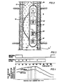
- FIG 1 schematically illustrates logging sonde 10 in a well bore 12 during logging operations.
- the sonde 10 includes a housing 16 in the shape of a cylindrical sleeve, which is designed for running through either small or large diameter production tubing.
- the small diameter sonde 10 may also have an eccentering device, such as the one shown and referred as 36 in Figure 2, for forcing the tool against well casing beneath the bottom end of tubing 14.
- Accelerator or pulsed neutron source 18 is mounted in the sonde with near detector 20 and far detector 22 mounted longitudinally above accelerator 18, with increasing axial distances. Acquisition, control and telemetry electronics 24 are shown schematically and will be described in more detail below.
- Electronics 24 serves among other functions, to control the timing of burst cycles of the neutron accelerator 18 the timing of detection time gates for near and far detectors 20, 22, and to telemeter count rate and other data via cable 26 and telemetry circuitry 28 to surface instrumentation 30 which includes computer 31.
- Computer 31 receives gamma ray spectral data from near and far detectors 20, 22 and processes and combines it according to the method of this invention to produce a signal representative of formation hydrocarbon (hereafter simply "oil") saturation S o .
- the signal may be recorded as a function of depth on recorder 32 along with a signal representative of the percentage of oil in the borehole fluid, C b . Water saturation S w may also be recorded.
- FIG. 1 The schematic illustration of Figure 1 shows application of the invention through tubing 14 in the well bore 12 which typically is lined with steel casing 13 and cemented in place through formations 8.
- Well head 27 at the earth's surface communicates with tubing 14.
- Sheave wheel 29 is shown schematically as controlling the movement of sonde 10 through tubing 14.
- the depth of the sonde 10 within well bore 12 is measured by encoders associated with sheave 29 as indicated by dotted lines 33, 34 from sheave 29 to computer 30 and recorder 32.
- FIG 2 illustrates an alternative sonde 10′ disposed in a well bore 12′ which may be an open hole but is more likely a cased hole beneath production tubing.
- Sonde 10′ includes an eccentering device such as bow spring 36 forcing housing 16′ against the wall of the casing or bore of the well.
- the through tubing sonde 10′ like the through tubing sonde 10 of Figure 1, has a neutron accelerator 18′ and progressively spaced apart near and far detectors 20′ and 22′.
- the outside diameter of sonde 10′ is preferably 2-1/2 inches.
- the neutron accelerator 18 or 18′ is operated to provide a burst of fast neutrons periodically, such that, e.g., 20 microsecond neutron bursts occur in a 100 microsecond cycle time, as illustrated in Figure 3.
- the first time gate A substantially coinciding with the neutron burst, is used to detect inelastic gamma rays produced by the fast neutrons, while the two other following time gates B and C may be used to detect gamma rays produced as the neutrons slow down to thermal energy and are captured by the nuclei of elements of formation or borehole.
- Figure 4 depicts the inelastic energy spectra of gamma ray counts as detected by near and far detectors 20 and 22 during time gate A.
- the inelastic energy spectra (and capture spectra from gates B and C) are obtained by accumulating the gate counts-per-channel signals from near and far detectors for a period long enough to give a statistically satisfactory spectrum, e.g., on the order of 20 seconds for the timing sequence of Figure 3. This is done under control of surface instrumentation 30 to output spectra as depicted for example in Figure 4.
- the surface instrumentation 30 is then reset to zero, and new channel count data for spectra for a new depth in the well bore 12 are accumulated.
- the method of the invention includes determining for each detector measured amounts of elements of the formation and borehole from a composite spectrum made up of weighted standard spectra of the constituents postulated to comprise the formation and the borehole.
- a composite spectrum made up of weighted standard spectra of the constituents postulated to comprise the formation and the borehole.
- the fraction of standard spectra which give the best fit of the composite spectrum to the unknown spectrum represent the relative proportions of the constituents in the formation and borehole.
- the proportions of the earth constituents of interest such as e.g. carbon, oxygen, silicon, calcium, iron, can be obtained.
- the 100 microsecond cycle illustrated in Figure 3 is set to enhance the statistical precision of the inelastic scattering gamma ray spectra.
- closely spaced neutron bursts have the disadvantage that background gamma rays, resulting in this instance predominantly from thermal neutron capture reactions between formation constituents and neutrons from one or more preceding bursts, will be present during the detection periods for the inelastic scattering gamma rays.
- Such capture gamma rays will of course be sensed by the near and far detectors and unless compensated for, will tend to confound the inelastic scattering gamma ray spectra.
- the counts detected by the near detector 20 and the far detector 22 in spectral gate B of Figure 3 may be used to correct the inelastic spectra detected in gate A for capture background gamma rays, according to the teaching of U.S. patent 4,232,220 issued in the name of Russel C. Hertzog and assigned to the assignee of the present application, wherein background spectra for both near and far spectra may be subtracted from the inelastic spectra detected in gate A resulting in new inelastic spectra corrected for background effects.
- U.S. patent 4,232,220 is incorporated herein by reference for its disclosure of correcting inelastic spectra with spectra derived from gates immediately following the neutron burst.
- more details of the sonde 10 can be found in the patent application from McKeon, Roscoe, Stoller already referred to.
- each of the hereabove mentioned equations (10) and (11) consists of a set of two equations.
- carbon yield C and oxygen yield O are respectively expressed as a linear function of two or more of the following parameters: S o , S w , C b or C o .
- F xy are coefficients representative of the environmental parmmeters affecting the oil saturation and borehole oil fraction; such parameters may e.g. be the borehole diameter, the logging sonde stand-off, the casing diameter. Am to coefficients "F xy ", subscript “o” refers to oxygen, “c” refers to carbon, “b” to borehole, “f” to formation and “k” to a constant. Coefficients "F xy " are determined experimentally once and for all under laboratory conditions. Again, equations (12A) and (13A) each include a set of two equations, one for each detector.
- equations (12A) and (13A) provide over equations (10) and (11) a better extrapolation of the coefficients and thus provide coefficients "F xy " which constitute a better representation of the actual environment than the " ⁇ - ⁇ " coefficients of equations (10) and (11).
- the invention provides an improved determination of the environmental coefficients "F xy " from equations (12A) and (13A) by using the net spectra of the inelastic gamma rays.
- a set of equations is established for each of the laboratory measurements above referred to: where U j corresponds to the number of counts of the j-th channel (or energy window) of the normalimed net spectrum of the inelastic gamma rays, "y i " is the yield of the i-th standard element, "A i j “ stands for the number of counts for the j-th channel of the i-th standard, "A cb “ is the carbon-borehole standard, “A cf “ is the carbon-formation standard, “A ob “ is the oxygen-borehole standard, and "A of " is the oxygen-formation standard.
- each set of equations U j includes as many equations as channel.
- the number of laboratory measurements is at least three, and preferably four.
- the six unknowns "F xy " are common to all four set of equations similar to equation (15) and derived from the four laboratory measurements.
- the four set of equations can be solved for the coefficients "F xy " by using a well known weighted least squares method.
- Equation (12A) and (13A) can be derived the following equations (16), (17), (18), and (19), the superscripts "n” and "f” respectively referring to the near detector and the far detector:
- C n F kc n + F cf n S o + F cb n C b
- C f F kc f + F cf f S o + F cb f C b
- n F ko n + F of n S w + F ob n C o
- O f F ko f + F of f S w + F ob f C o
- C n and O n on the one hand, C f and O f on the other hand, are combined so as to form the differences (C n - O n ) and (C f - O f ).
- These differences can be, according to the invention, expressed in different ways, depending upon the linear functions expressing C and O respectively.
- C-O can also be expressed, by using equation (10) and (11):
- C n - O n ( ⁇ n - ⁇ n ) + ( ⁇ n - ⁇ n )S o + ( ⁇ n - ⁇ n )C b
- C f - O f ( ⁇ f - ⁇ f ) + ( ⁇ f - ⁇ f )S o + ( ⁇ f - ⁇ f )C b
- Equations (20) and (21), or (22) and (23) are thus solved for the unknowns S o and C b .
- Equation (24) in developed form becomes:
- [S mod ] matrix is thus a function of S o and C b and includes a first standard or variable function [S 1,mod ] corresponding to C b and a second standard or variable function [S 2,mod ] corresponding to S o .
- Equations 27 to 30 refers to carbon. Similar calculations can be carried out for oxygen in order to provide a first and a second variable function corresponding respectively to S w (saturation of water in the formation) and to C o (saturation of water in the borehole fluid).
- Equation (35), (36) and (37) can be solved through known mathematical process, such as Lagrange multipliers, (see e.g. "Methoden der Mathematischen Physik” from R. Courant and D. Hilbert, 1968, Springer-Verlag, Heidelberg, page 190) or variable substitution; the latter is preferable since it allows one to reduce the matrix size.
- equation (35) As can be seen from equation (35), and especially from the standard matrix [S], the standards for respectively the near and the far detector are combined or correlated.
- the matrix method hereabove described and leading to equation (35) provides the same advantages as the method previously described based on the differences C - O, especially by providing additional information resulting from the combination of data from the near and far detector. This allows one to gain full benefit of using two detectors.
- the "matrix method” brings a slight advantage over the method based on the differences C n - O n and C f - O f , (equations 20, 21, or 22, 23).
- both methods allow one to correlate data from near and far detector, the correlation is carried out at a respective step which differs in time from one method to the other.
- the "difference C-O method” correlates the carbon and oxygen yields C and O which are already processed data, while the matrix method correlates the data issued from the detectors, before any process besides a gain and offset correction and a background subtraction.
- the "difference C - O method” uses information from both detectors separately to provide separate carbon and oxygen yields for each detector, which are then combined in order to calculate S o and C b .
- the matrix method combines or correlates the near and far detectors data at the beginning of the process.
- the matrix method does not require one to determine carbon and oxygen yields since the matrix method implies a change of variables in the matrix [S] [y] from the yields y cn , y cf to the unknown oil saturations S o and C b .
- the present invention also allows the determination of one unknown, either S o or C b , assuming the other (C b or S o ) is already available from other sources. This results in an improved precision on the unknown. Furthermore, in this case the measurements can be carried out with a logging tool provided with a single detector. In contrast, two detectors are needed for determining simultaneously both S o and C b .
Description
- This invention relates to nuclear well logging method for determining the nature of fluids in formations through which a borehole is formed as well as the nature of fluids in the borehole. More particularly, the invention relates to determining the hydrocarbon saturation (or its correlative, water saturation) of formations adjacent a borehole by nuclear radiation logging. Still more particularly, the invention relates to inelastic gamma ray spectrum logging of a formation with correction for gamma rays from borehole fluids.
- A major goal of well logging is to establish the fraction of pore space in the earth formation occupied by hydrocarbons. Three methods of doing so have been developed in the prior art. The first two methods are electrical resistivity and thermal neutron decay methods which measure the water saturation Sw, and the difference, So = 1 - Sw, is the saturation of all other liquids and gases. The term So, or "oil" saturation, will be used hereafter to refer not only to liquid hydrocarbons, but also to gas. Both the electrical resistivity and thermal neutron decay methods depend upon the presence of salts dissolved in the water and, for that reason, are less effective in fresh water than in salt water environments.
- The third known method is based on the fact that hydrocarbons contain carbon and water contains oxygen. When a high energy neutron, usually called "fast neutron", is scattered inelastically from a carbon atom, a 4.4 MeV gamma ray is emitted. When a fast neutron is scattered from an oxygen atom, a 6.1 MeV gamma ray is emitted among others. Therefore, a logging apparatus which counts the number of 4.4 MeV gamma rays and the number of 6.1 MeV gamma rays and determines their ratio should be, under ideal conditions, able to provide a measure of the ratio of carbon to oxygen in the formation. Such measurements are known in the art as carbon/oxygen or simply, C/O measurements or C/O logs. Moreover, a calcium/silicon ratio can also be obtained. Comparison of these two ratios permits the user to distinguish carbon in calcium carbonates from that in hydrocarbons.
- In cased hole wells, where the salinity or salt content of a water-saturated zone is not known, is very low, or has been altered by production by water injection, the C/O measurement is the only alternative to resistivity and neutron decay methods.
- Under actual field conditions, however, the well bore may contain hydrocarbons (in the form of oil or gas) and water. Consequently, C/O measurements of the formation are contaminated or "corrupted" with gamma rays resulting from fast neutron interaction with carbon and oxygen atoms of fluids in the borehole. In addition, lithologies, such as dolomite and limestone, contain carbon atoms. Such contamination of the inelastic gamma ray spectral data, and ultimately of the so determination, may be eliminated if the porosity, lithology, borehole configuration and hydrocarbon content of the fluid in the well bore is known.
- Characteristics as a function of depth of a cased well, such as porosity and lithology of the formation and the borehole configuration may be known. But C/O logging measurements of cased, producing wells have required that the well be "shut-in" so that the borehole fluid components may be known better. However, even with shut-in wells, the content of borehole fluid is not always known well enough.
- As described in US pending application serial number 07/203,397 filed on June 7, 1988 in the name of MKeon, Roscoe, Stoller (corresponding to EP-A-0 348 260), the C/O measurements are carried out by using a logging tool provided with a near and a far detector. The relative amounts of carbon and oxygen Cn, On, as measured from the near detector, and the relative amounts of carbon and oxygen Cf, Of, as measured from the far detector, are obtained. A least squares analysis is performed to determine Cn, On from the energy spectrum (counts versus energy) acquired from the near detector, using standard spectra for the near detector, Cf and Of are determined from the energy spectrum as measured from the far detector using standard spectra for the far detector. The analysis is performed at each logging depth in the borehole. Next, the carbon and oxygen determinations of the near and far detectors are combined to determine oil saturation of the formation (So) and/or the oil percentage in the borehole (Cb). This is done by assuming that the total carbon and oxygen measured as indicated above are equal to the sum of the carbon and oxygen yields from the rock matrix of the formation, the pore space fluid, and the borehole fluid:


- The coefficients α, β, δ, η, µ and ν are then determined under laboratory conditions by taking four measurements under the same conditions except varying So and Oh. For example, the conditions of a 10 inch borehole, a 7" (17.8 cm) - 23 lb per foot (15.5 kg/m) casing in a 33 p.u. (porosity unit) sandstone formation may be established, for calibration, and then C and O from near and far detectors may be measured with the logging tool to be used in the field. The table below illustrates the boratory measurements:
BOREHOLE FORMATION MEASURE CONDITION water water Cn, On Cf,Of water oil Cn,On Cf,Of oil water Cn,On Cf,Of oil oil Cn,On Cf,Of - The superscripts "n" and "f" refer respectively to the near and far detector.
- These four measurements with three unknowns are for near and far carbon and oxygen. Since the equations (3) and (4) are over determined, the coefficients α, β, δ, η, µ, and ν, for both the near and far measurents, are obtained using conventional least squares procedures.
- Next, a carbon/oxygen ratio is formed for each of the near and far detectors, i.e. Cn/On and Cf/Of, leading to two equations which are solved for So and Cb.
- At each depth in the borehole, a signal representative of oil saturation So, and water saturation Sw = 1 - So and percentage oil in the borehole Cb, is recorded.
- Although the above referred known method represents a substantial improvement, one could increase the benefit from the use of two different detectors by more efficiently combining or correlating measurements from respective detectors. Furthermore, the determination of the α, β, δ, η, µ, and ν coefficients could be improved.
- Consequently, while the known technology above described represents efforts to advance the nuclear logging art, the need remains for a method and apparatus by which the oil saturation in the formation So and/or in the borehole fluid Cb may be more accurately determined through carbon and oxygen measurement using logging techniques, with correction for corrupting gamma rays of unknown amounts of hydrocarbons in the borehole.
- A principal object of preferred embodiments of this invention, therefore, is to provide a logging method where carbon and oxygen measurements at near and far detectors are fully combined or correlated to produce a representation of oil saturation of the formation, and are corrected for the gamma rays produced by carbon and oxygen atoms in the borehole.
- It is a first particular object of the invention to provide the determination of the oil saturation in the formation So and/or the oil percentage in the borehole fluid Cb.
- According to the invention, these and further objects are attained by a method for determining the hydrocarbon saturation So in an earth formation surrounding a borehole, comprising:
- irradiating the formation with a source of neutrons of sufficient energy to interact with atoms of the formation and the borehole, according to inelastic neutron reactions;
- detecting and counting the gamma rays resulting from said reactions at at least one location longitudinally spaced from said source;
- expressing the measured carbon (C) and oxygen (O) yields respectively as a first and second linear function of So, Sw the water saturation in the formation, Cb the hydrocarbon saturation in the borehole, and/or Co the water saturation in the borehole;
- - combining the respective measured carbon and oxygen yields (C, O) so as to form the difference C - O; and
- - solving for the unknown So.
- Alternately, the invention is directed to the determination of the hydrocarbon saturation Cb, while So is known from another source.
- In a further embodiment, the invention deals with a method for the simultaneous determination of Cb and So, comprising:
- irradiating the formation with a source of neutrons of sufficient energy to interact with atoms of the formation and the borehole, according to inelastic neutron reactions;
- detecting and counting the gamma rays resulting from said reactions, at at least two locations longitudinally spaced from said source and including a first location and at a second location, said first location (near) being disposed a distance from said source smaller than said second location (far);
- expressing the measured carbon (C) and oxygen (O) yields respectively as a first and second linear function of So, Sw the nater saturation in the formation, Cb, and/or Co water saturation in the borehole;
- combining the respective carbon and oxygen yields (Cn, On) for the near detector, and the respective carbon and oxygen yields (Cf, Of) for the far detector so as to form the differences Cn - On and Cf - Of; and
- solving for the unknowns So and Cb.
- The differences Cn - On and Cf - Of are expressed as


- Alternately, the differences are expressed as


- In one embodiment, the first linear function is of the form


- The invention further contemplates an apparatus for determining the hydrocarbon saturation So in an earth formation surrounding a borehole, comprising:
- means for irradiating the formation with a source of neutrons of sufficient energy to interact with atoms of the formation and the borehole, according to inelastic neutron reactions;
- means for detecting and counting the gamma rays resulting from said reactions at at least one location longitudinally spaced from said source;
- means for expressing the measured carbon (C) and oxygen (O) yields respectively as a first and second linear function of So, Sw the water saturation in the formation, Cb the hydrocarbon saturation in the borehole, and/or Co the water saturation in the borehole;
- means for combining the respective measured carbon and oxygen yields (C, O) so as to form the difference C - O; and
- means for solving for the unknown So.
- The characteristics and advantages of the invention will appear better from the description to follow, given by way of a nonlimiting example, with reference to the appended drawings in which:
-
- Fig. 1 is a schematic illustration of a through tubing version of a well logging tool within a borehole;
- Fig 2 is an alternative embodiment of the tool for use in large diameter tubing;
- Fig 3 illustrates timing schedules for neutron bursts and counting gates; and
- Fig 4 is an illustration of gamma ray count spectra obtained by near and far detectors.
- Figure 1 schematically illustrates logging
sonde 10 in a well bore 12 during logging operations. Thesonde 10 includes ahousing 16 in the shape of a cylindrical sleeve, which is designed for running through either small or large diameter production tubing. Although not illustrated in Figure 1, thesmall diameter sonde 10 may also have an eccentering device, such as the one shown and referred as 36 in Figure 2, for forcing the tool against well casing beneath the bottom end of tubing 14. Accelerator or pulsed neutron source 18 is mounted in the sonde withnear detector 20 andfar detector 22 mounted longitudinally above accelerator 18, with increasing axial distances. Acquisition, control andtelemetry electronics 24 are shown schematically and will be described in more detail below.Electronics 24 serves among other functions, to control the timing of burst cycles of the neutron accelerator 18 the timing of detection time gates for near andfar detectors cable 26 andtelemetry circuitry 28 to surfaceinstrumentation 30 which includescomputer 31.Computer 31 receives gamma ray spectral data from near andfar detectors recorder 32 along with a signal representative of the percentage of oil in the borehole fluid, Cb. Water saturation Sw may also be recorded. - The schematic illustration of Figure 1 shows application of the invention through tubing 14 in the well bore 12 which typically is lined with
steel casing 13 and cemented in place through formations 8. Wellhead 27 at the earth's surface communicates with tubing 14.Sheave wheel 29 is shown schematically as controlling the movement ofsonde 10 through tubing 14. The depth of thesonde 10 within well bore 12 is measured by encoders associated withsheave 29 as indicated bydotted lines sheave 29 tocomputer 30 andrecorder 32. - Figure 2 illustrates an
alternative sonde 10′ disposed in a well bore 12′ which may be an open hole but is more likely a cased hole beneath production tubing.Sonde 10′ includes an eccentering device such asbow spring 36 forcinghousing 16′ against the wall of the casing or bore of the well. The throughtubing sonde 10′, like the throughtubing sonde 10 of Figure 1, has a neutron accelerator 18′ and progressively spaced apart near andfar detectors 20′ and 22′. The outside diameter ofsonde 10′ is preferably 2-1/2 inches. - The neutron accelerator 18 or 18′ is operated to provide a burst of fast neutrons periodically, such that, e.g., 20 microsecond neutron bursts occur in a 100 microsecond cycle time, as illustrated in Figure 3. The first time gate A, substantially coinciding with the neutron burst, is used to detect inelastic gamma rays produced by the fast neutrons, while the two other following time gates B and C may be used to detect gamma rays produced as the neutrons slow down to thermal energy and are captured by the nuclei of elements of formation or borehole.
- Figure 4 depicts the inelastic energy spectra of gamma ray counts as detected by near and
far detectors surface instrumentation 30 to output spectra as depicted for example in Figure 4. Thesurface instrumentation 30 is then reset to zero, and new channel count data for spectra for a new depth in the well bore 12 are accumulated. - Two gamma ray count functions, referred to as g(E)near and g(E)far on Fig. 4, are obtained at each depth of the borehole of
sonde 16 fromsurface instrumentation 30 after receipt of gamma ray count and pulse height information fromcircuitry 24. The method of the invention includes determining for each detector measured amounts of elements of the formation and borehole from a composite spectrum made up of weighted standard spectra of the constituents postulated to comprise the formation and the borehole. As described in U.S. patent 3,521,064 issued July 21, 1970 to Moran and Tittman , the fraction of standard spectra which give the best fit of the composite spectrum to the unknown spectrum represent the relative proportions of the constituents in the formation and borehole. By appropriate selection of the standards, the proportions of the earth constituents of interest, such as e.g. carbon, oxygen, silicon, calcium, iron, can be obtained. - The 100 microsecond cycle illustrated in Figure 3 is set to enhance the statistical precision of the inelastic scattering gamma ray spectra. But closely spaced neutron bursts have the disadvantage that background gamma rays, resulting in this instance predominantly from thermal neutron capture reactions between formation constituents and neutrons from one or more preceding bursts, will be present during the detection periods for the inelastic scattering gamma rays. Such capture gamma rays will of course be sensed by the near and far detectors and unless compensated for, will tend to confound the inelastic scattering gamma ray spectra.
- The counts detected by the
near detector 20 and thefar detector 22 in spectral gate B of Figure 3 may be used to correct the inelastic spectra detected in gate A for capture background gamma rays, according to the teaching of U.S. patent 4,232,220 issued in the name of Russel C. Hertzog and assigned to the assignee of the present application, wherein background spectra for both near and far spectra may be subtracted from the inelastic spectra detected in gate A resulting in new inelastic spectra corrected for background effects. U.S. patent 4,232,220 is incorporated herein by reference for its disclosure of correcting inelastic spectra with spectra derived from gates immediately following the neutron burst. Furthermore, more details of thesonde 10 can be found in the patent application from McKeon, Roscoe, Stoller already referred to. - According to the teaching from the McKeon, Roscoe and Stoller pending patent application already referred to, the respective yields, as measured, of carbon "C" and oxygen "O", are expressed as follows:


Borehole fluid Formation fluid Water Water Water Oil Oil Water Oil Oil - It has to be born in mind that the measurements in the borehole actually include two sets of measurements, one for the near detector and the other for the far detector. Accordingly, each of the hereabove mentioned equations (10) and (11) consists of a set of two equations.
- According to the invention, carbon yield C and oxygen yield O are respectively expressed as a linear function of two or more of the following parameters: So, Sw, Cb or Co. The general form of these linear functions is:


- By way of example, C and 0 can be expressed as follows:


- When adjusting the equation coefficients to the actual environmental conditions of the measurements, one has to determine the adequate coefficients by extrapolation from the coefficients determined experimentally. In that respect equations (12A) and (13A) provide over equations (10) and (11) a better extrapolation of the coefficients and thus provide coefficients "Fxy" which constitute a better representation of the actual environment than the "α-ν" coefficients of equations (10) and (11).
- Furthermore, the invention provides an improved determination of the environmental coefficients "Fxy" from equations (12A) and (13A) by using the net spectra of the inelastic gamma rays. A set of equations is established for each of the laboratory measurements above referred to:

- Moreover, according to an important aspect of the present invention, it is proposed an improved model for determining the oil So and water Sw saturation in the formation and the oil Cb and water Go saturation in the borehole.
- From equations (12A) and (13A) can be derived the following equations (16), (17), (18), and (19), the superscripts "n" and "f" respectively referring to the near detector and the far detector:


- From equations 16-19, the carbon and oxygen yields for the near detector (Cn and On) are combined on the one hand, and the carbon and oxygen yields for the far detector (Cf and Of) are combined on the other hand. The two equations thus obtained are used to solve for the two unknowns So and Cb.
- According to of the invention, Cn and On on the one hand, Cf and Of on the the other hand, are combined so as to form the differences (Cn - On) and (Cf - Of). These differences can be, according to the invention, expressed in different ways, depending upon the linear functions expressing C and O respectively. By way of example, the differences (Cn-On) and (Cf-Of) can be expressed as follows, based on equations (16), (17), (18) and (19), and So = 1 - Sw and Cb = 1-Co:


- Alternately, the differences C-O can also be expressed, by using equation (10) and (11):


- Equations (20) and (21), or (22) and (23) are thus solved for the unknowns So and Cb.
- Forming the difference C - O between carbon and oxygen yields according to the invention, compared to the ratio C/O as it is known in the art (see the US patent application pending already referred to) improves substantially the accuracy and precision of the measurements. As a matter of fact, C and O show variations of similar value magnitude (i.e. around 0.05) and of opposite signs, while O has an absolute value greater (between 0.1 and 0.2) than C (between 0 and 0.05). The difference C - O will enhance the variations of C and O and thus provide more precise and accurate measurements. Furthermore, the data from respective near and far detector are combined in a way to provide a full benefit of using two detectors, as it will be further detailed.
- Here below is described another embodiment of the inventions for the determination of So and Cb, and which constitutes an alternative method to the above described method based on the differences Cn-On and Cf-Of.
- The measured carbon and oxygen yields (C, O) are expressed in the following matrix form:


- Equation (24) in developed form, becomes:

- Elemental yields "yi", i.e. respectively carbon yield C and oxygen O, are then expressed as a function of So and Ob, and then introduced in equation (24). To this end, either equations (10),(11) or equations (16)-(19) can be used alternately. The following describes the calculation referring to carbon by using equations (16) and (17). The carbon yields for the near detector "ycn" and the far detector "ycf" are introduced in equation (24), which thus becomes:


- All the above mentioned calculation (
equations 27 to 30) refers to carbon. Similar calculations can be carried out for oxygen in order to provide a first and a second variable function corresponding respectively to Sw (saturation of water in the formation) and to Co (saturation of water in the borehole fluid). - C and O can also be introduced in equation (24) using equations (10) and (11) (instead of equations 16-19 as hereabove described). Thus, equation (24) becomes:


- Finally, calculations resulting either from equations 27-30 or from equations 31-34, equation (26) can be written as follows:

- In order to improve further the hereabove described matrix method, and make full use of the available information, one may introduce the following constraints:


- Equation (35), (36) and (37) can be solved through known mathematical process, such as Lagrange multipliers, (see e.g. "Methoden der Mathematischen Physik" from R. Courant and D. Hilbert, 1968, Springer-Verlag, Heidelberg, page 190) or variable substitution; the latter is preferable since it allows one to reduce the matrix size.
- As can be seen from equation (35), and especially from the standard matrix [S], the standards for respectively the near and the far detector are combined or correlated. The matrix method hereabove described and leading to equation (35) provides the same advantages as the method previously described based on the differences C - O, especially by providing additional information resulting from the combination of data from the near and far detector. This allows one to gain full benefit of using two detectors.
- As a further comparison between the different embodiments of the invention, the "matrix method" (equation 35) brings a slight advantage over the method based on the differences Cn - On and Cf - Of, (
equations - Although the above description contemplates the determination of both So and Cb, the present invention also allows the determination of one unknown, either So or Cb, assuming the other (Cb or So) is already available from other sources. This results in an improved precision on the unknown. Furthermore, in this case the measurements can be carried out with a logging tool provided with a single detector. In contrast, two detectors are needed for determining simultaneously both So and Cb.
Claims (10)
- A method for determining one of the hydrocarbon saturation So in an earth formation surrounding a borehole and the hydrocarbon saturation Cb in the borehole, the method comprising:irradiating the formation with neutrons of sufficient energy to interact with atoms of the formation and the borehole, according to inelastic neutron reactions;detecting and counting the gamma rays resulting from said reactions at at least one location longitudinally spaced from the point of emission of the neutrons;forming gamma ray spectrum signals from said gamma rays and deriving from said signals the carbon and oxygen yields; andexpressing the measured carbon and oxygen yields respectively as first and second linear functions of two or more of the following parameters: So, the water saturation Sw in the formation, Cb and the water saturation Co in the borehole;the method being characterised by forming the difference between the respective measured carbon and oxygen yields, and deriving the unknown one of So and Cb from said difference.
- The method of claim 1, wherein said detecting and counting step is performed at first and second locations longitudinally spaced from said emission point, said first location being nearer said emission point than is said second location, forming respective first and second linear functions and respective differences between measured carbon and oxygen yields for each of said locations, and deriving one or both of So and Cb from said differences.
- The method of claim 1 or claim 2, wherein the or each first linear function is of the form


- The method of claim 1 or claim 2, wherein the or each first linear function is of the form


- The method of claim 4, wherein the or each difference is expressed as

- Apparatus for determining one of the hydrocarbon saturation So in an earth formation surrounding a borehole and the hydrocarbon saturation Cb in the borehole, the apparatus comprising:source means (18) for irradiating the formation with neutrons of sufficient energy to interact with atoms of the formation and the borehole, according to inelastic neutron reactions;means (20 or 22) for detecting and counting the gamma rays resulting from said reactions at at least one location longitudinally spaced from the source means (18);means (24) for forming gamma ray spectrum signals from said gamma rays; andcalculating means (31) for deriving from said signals the carbon and oxygen yields and for expressing the measured carbon and oxygen yields respectively as first and second linear functions of two or more of the following parameters: So, the water saturation Sw in the formation, Cb and the water saturation Co in the borehole;characterised in that the calculating means (31) is arranged to form the difference between the respective measured carbon and oxygen yields, and to derive the unknown one of So and Cb from said difference.
- The apparatus of claim 6, wherein said detecting and counting means comprises first and second detecting and counting means (20,22) positioned at first and second locations longitudinally spaced from said source means (18), said first location being nearer said source means than is said second location, and said calculating means (31) is arranged to form respective first and second linear functions and respective differences between measured carbon and oxygen yields for each of said locations, and to derive one or both of So and Cb from said differences.
- The apparatus of claim 6 or claim 7, wherein the or each first linear function is of the form


- The apparatus of claim 6 or claim 7, wherein the or each first linear function is of the form


- The apparatus of claim 9, wherein the or each difference is expressed as

Applications Claiming Priority (2)
| Application Number | Priority Date | Filing Date | Title |
|---|---|---|---|
| US521804 | 1990-05-09 | ||
| US07/521,804 US5055676A (en) | 1990-05-09 | 1990-05-09 | Method for determining oil and water saturation in earth formation surrounding a borehole |
Publications (3)
| Publication Number | Publication Date |
|---|---|
| EP0465276A2 EP0465276A2 (en) | 1992-01-08 |
| EP0465276A3 EP0465276A3 (en) | 1993-01-13 |
| EP0465276B1 true EP0465276B1 (en) | 1996-10-02 |
Family
ID=24078244
Family Applications (1)
| Application Number | Title | Priority Date | Filing Date |
|---|---|---|---|
| EP91401189A Expired - Lifetime EP0465276B1 (en) | 1990-05-09 | 1991-05-07 | Method for determining oil and water saturation in earth formation surrounding a borehole |
Country Status (2)
| Country | Link |
|---|---|
| US (1) | US5055676A (en) |
| EP (1) | EP0465276B1 (en) |
Families Citing this family (18)
| Publication number | Priority date | Publication date | Assignee | Title |
|---|---|---|---|---|
| US5374823A (en) * | 1993-10-28 | 1994-12-20 | Computalog U.S.A., Inc. | Pulsed neutron decay tool for measuring gamma radiation energy spectra for fast neutron inelastic collisions and thermal neutron capture events |
| US5699246A (en) * | 1995-09-22 | 1997-12-16 | Schlumberger Technology Corporation | Method to estimate a corrected response of a measurement apparatus relative to a set of known responses and observed measurements |
| DZ2226A1 (en) * | 1996-05-10 | 2002-12-03 | Petroleum Res & Dev Nv | Method for recording an earth formation using recycled alpha data. |
| US5808298A (en) * | 1997-02-11 | 1998-09-15 | Western Atlas International, Inc. | Method for determining formation hydrocarbon saturation and wellbore hydrocarbon holdup from multidetector carbon-oxygen measurements |
| US6959763B2 (en) * | 2002-04-01 | 2005-11-01 | Schlumberger Technology Corporation | Method and apparatus for integrated horizontal selective testing of wells |
| US7282704B2 (en) * | 2004-05-28 | 2007-10-16 | Baker Hughes Incorporated | Method for determining formation porosity and gas saturation in a gas reservoir |
| US7365308B2 (en) * | 2005-07-26 | 2008-04-29 | Baker Hughes Incorporated | Measurement of formation gas saturation in cased wellbores using pulsed neutron instrumentation |
| US7566869B2 (en) * | 2005-07-26 | 2009-07-28 | Baker Hughes Incorporated | Measurement of water-oil saturation using pulsed neutron instrumentation |
| US7791017B2 (en) * | 2007-07-23 | 2010-09-07 | Schlumberger Technology Corporation | Method to simultaneously determine pore hydrocarbon density and water saturation from pulsed neutron measurements |
| US7667192B2 (en) * | 2007-08-16 | 2010-02-23 | Schlumberger Technology Corporation | Thermal neutron porosity from neutron slowing-down length, formation thermal neutron capture cross section, and bulk density |
| US7999220B2 (en) * | 2008-05-30 | 2011-08-16 | Precision Energy Services, Inc. | Borehole measurements using a fast and high energy resolution gamma ray detector assembly |
| CN102159970B (en) * | 2008-08-26 | 2014-12-10 | 普拉德研究及开发股份有限公司 | Method and apparatus for determining formation water saturation during drilling |
| US8614578B2 (en) * | 2009-06-18 | 2013-12-24 | Schlumberger Technology Corporation | Attenuation of electromagnetic signals passing through conductive material |
| US10324224B2 (en) | 2010-09-02 | 2019-06-18 | Baker Huges, A Ge Company, Llc | Elemental concentration determination using neutron-induced activation gamma radiation |
| US9228427B2 (en) * | 2011-10-27 | 2016-01-05 | Saudi Arabian Oil Company | Completion method to allow dual reservoir saturation and pressure monitoring |
| CN108661632B (en) * | 2018-05-07 | 2022-02-11 | 何巍巍 | High-precision carbon-oxygen ratio logging method |
| WO2021194533A1 (en) * | 2020-03-24 | 2021-09-30 | Baker Hughes Oilfield Operations Llc | Mixed salinity impact on interpretation and remedial detection technique |
| CN112031742B (en) * | 2020-09-03 | 2023-07-04 | 中海油田服务股份有限公司 | Carbon-oxygen ratio energy spectrum logging saturation interpretation method based on database |
Family Cites Families (7)
| Publication number | Priority date | Publication date | Assignee | Title |
|---|---|---|---|---|
| US3780302A (en) * | 1971-09-20 | 1973-12-18 | Texaco Inc | Pulsed neutron logging system |
| GB1396642A (en) * | 1973-03-29 | 1975-06-04 | Texaco Development Corp | Borehole gamma ray spectroscopy |
| US3849646A (en) * | 1973-06-05 | 1974-11-19 | Texaco Inc | Inelastic neutron scattering methods to locate coal and oil shale zones |
| AU533314B2 (en) * | 1978-01-16 | 1983-11-17 | Schlumberger Technology B.V. | Nuclear well-logging |
| US4380701A (en) * | 1980-10-02 | 1983-04-19 | Texaco Inc. | Nuclear well logging with neutron source and separate spaced radiation detectors to determine silicon/oxygen ratio |
| US4691102A (en) * | 1985-06-17 | 1987-09-01 | Halliburton Company | Borehole compensation method and apparatus using variations in relative borehole components |
| ES2038835T3 (en) * | 1988-06-07 | 1993-08-01 | Schlumberger Limited | METHOD AND APPARATUS FOR THE EXPLORATION OF WELLS WITH CARBON / OXYGEN. |
-
1990
- 1990-05-09 US US07/521,804 patent/US5055676A/en not_active Expired - Lifetime
-
1991
- 1991-05-07 EP EP91401189A patent/EP0465276B1/en not_active Expired - Lifetime
Non-Patent Citations (1)
| Title |
|---|
| GRAU J. A., SCHWEITZER J. S.: "PROMPT Y-RAY SPECTRAL ANALYSIS OF WELL DATA OBTAINED WITH NAI(TL) AND 14 MEV NEUTRONS.", INTERNATIONAL JOURNAL OF RADIATION APPLICATIONS ANDINSTRUMENTATION PART E: NUCLEAR GEOPHYSICS., PERGAMON PRESS LTD., EXETER., GB, vol. 01., no. 02., 1 January 1987 (1987-01-01), GB, pages 157 - 165., XP000140513 * |
Also Published As
| Publication number | Publication date |
|---|---|
| EP0465276A2 (en) | 1992-01-08 |
| US5055676A (en) | 1991-10-08 |
| EP0465276A3 (en) | 1993-01-13 |
Similar Documents
| Publication | Publication Date | Title |
|---|---|---|
| US4937446A (en) | Carbon/oxygen well logging method and apparatus | |
| EP0465276B1 (en) | Method for determining oil and water saturation in earth formation surrounding a borehole | |
| US5440118A (en) | Methods and apparatus for determining formation lithology by gamma ray spectroscopy | |
| US5081351A (en) | Method and apparatus for borehole correction in capture gamma ray spectroscopy measurements | |
| US5105080A (en) | Method and apparatus for determining the respective contributions of borehole and earth formation in gamma ray spectroscopy | |
| US7365307B2 (en) | Sigma/porosity tools with neutron monitors | |
| US4464569A (en) | Method and apparatus for spectroscopic analysis of a geological formation | |
| US4055763A (en) | Neutron characteristic and spectroscopy logging methods and apparatus | |
| US7253402B2 (en) | Apparatus and method for determining thermal neutron capture cross section of a subsurface formation from a borehole using multiple detectors | |
| US5349184A (en) | Method and apparatus for reducing matrix density effects on porosity measurements during epithermal neutron porosity well logging | |
| US4585939A (en) | Multi-function natural gamma ray logging system | |
| US7408150B1 (en) | Well logging method for determining formation characteristics using pulsed neutron capture measurements | |
| US4507554A (en) | Method and apparatus for determining borehole and formation constituents | |
| US4641028A (en) | Neutron logging tool | |
| US5045693A (en) | Carbon/oxygen well logging method and apparatus | |
| US6289283B1 (en) | Downhole tool data correction method and apparatus | |
| US7254486B2 (en) | Method and apparatus for shale bed detection in deviated and horizontal wellbores | |
| US7112783B2 (en) | Neutron measurement method for determining porosity of a formation surrounding a borehole | |
| US4232220A (en) | Background subtraction system for pulsed neutron logging of earth boreholes | |
| US5420422A (en) | Methods and apparatus for epithermal neutron porosity logging | |
| US4404467A (en) | Salinity and lithology determination from the sodium and chlorine activation lines | |
| US4208580A (en) | Lithology determination from the calcium and magnesium activation lines | |
| US4446369A (en) | Method and system for radioactive assaying | |
| EP0348260B1 (en) | Carbon/oxygen well logging method and apparatus | |
| CA1168379A (en) | Spectroscopic analysis with background compensation |
Legal Events
| Date | Code | Title | Description |
|---|---|---|---|
| PUAI | Public reference made under article 153(3) epc to a published international application that has entered the european phase |
Free format text: ORIGINAL CODE: 0009012 |
|
| AK | Designated contracting states |
Kind code of ref document: A2 Designated state(s): FR GB NL |
|
| PUAL | Search report despatched |
Free format text: ORIGINAL CODE: 0009013 |
|
| AK | Designated contracting states |
Kind code of ref document: A3 Designated state(s): FR GB NL |
|
| 17P | Request for examination filed |
Effective date: 19930709 |
|
| 17Q | First examination report despatched |
Effective date: 19940817 |
|
| GRAG | Despatch of communication of intention to grant |
Free format text: ORIGINAL CODE: EPIDOS AGRA |
|
| GRAH | Despatch of communication of intention to grant a patent |
Free format text: ORIGINAL CODE: EPIDOS IGRA |
|
| GRAH | Despatch of communication of intention to grant a patent |
Free format text: ORIGINAL CODE: EPIDOS IGRA |
|
| GRAA | (expected) grant |
Free format text: ORIGINAL CODE: 0009210 |
|
| AK | Designated contracting states |
Kind code of ref document: B1 Designated state(s): FR GB NL |
|
| PG25 | Lapsed in a contracting state [announced via postgrant information from national office to epo] |
Ref country code: NL Free format text: LAPSE BECAUSE OF FAILURE TO SUBMIT A TRANSLATION OF THE DESCRIPTION OR TO PAY THE FEE WITHIN THE PRESCRIBED TIME-LIMIT Effective date: 19961002 |
|
| ET | Fr: translation filed | ||
| NLV1 | Nl: lapsed or annulled due to failure to fulfill the requirements of art. 29p and 29m of the patents act | ||
| PLBE | No opposition filed within time limit |
Free format text: ORIGINAL CODE: 0009261 |
|
| STAA | Information on the status of an ep patent application or granted ep patent |
Free format text: STATUS: NO OPPOSITION FILED WITHIN TIME LIMIT |
|
| 26N | No opposition filed | ||
| REG | Reference to a national code |
Ref country code: GB Ref legal event code: IF02 |
|
| PGFP | Annual fee paid to national office [announced via postgrant information from national office to epo] |
Ref country code: GB Payment date: 20070502 Year of fee payment: 17 |
|
| PGFP | Annual fee paid to national office [announced via postgrant information from national office to epo] |
Ref country code: FR Payment date: 20070510 Year of fee payment: 17 |
|
| GBPC | Gb: european patent ceased through non-payment of renewal fee |
Effective date: 20080507 |
|
| REG | Reference to a national code |
Ref country code: FR Ref legal event code: ST Effective date: 20090119 |
|
| PG25 | Lapsed in a contracting state [announced via postgrant information from national office to epo] |
Ref country code: FR Free format text: LAPSE BECAUSE OF NON-PAYMENT OF DUE FEES Effective date: 20080602 |
|
| PG25 | Lapsed in a contracting state [announced via postgrant information from national office to epo] |
Ref country code: GB Free format text: LAPSE BECAUSE OF NON-PAYMENT OF DUE FEES Effective date: 20080507 |